1
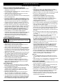
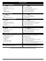
RULES FOR SAFE OPERATION
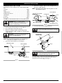
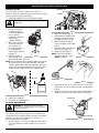
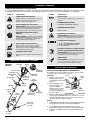
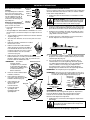
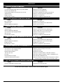
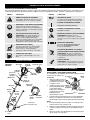
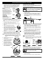
SAFETY AND INTERNATIONAL SYMBOLS
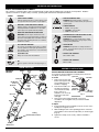
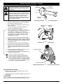
This operator's manual describes safety and international symbols and pictographs that may appear on this product. Read the
operator's manual for complete safety, assembly, operating and maintenance and repair information.
SYMBOL
SYMBOL
MEANING
• SAFETY ALERT SYMBOL
MEANING
• KEEP BYSTANDERS AWAY
Indicates danger, warning or caution. May be used
in conjunction with other symbols or pictographs.
WARNING: Keep all bystanders, especially
children and pets, at least 50 feet (15 m) from the
operating area.
• WARNING - READ OPERATOR'S MANUAL
• CHOKE CONTROL
Read the operator’s manual(s) and follow all warnings
and safety instructions. Failure to do so can result in
serious injury to the operator and/or bystanders.
1. • FULL choke position
2. • PARTIAL choke position
3. • RUN choke position
• WEAR EYE AND HEARING PROTECTION
• THROWN OBJECTS AND ROTATING CUTTER
CAN CAUSE SEVERE INJURY
WARNING: Thrown objects and loud noise can
cause severe eye injury and hearing loss. Wear eye
protection meeting ANSI Z87.1 standards and ear
protection when operating this unit. Use a full face
shield when needed.
WARNING: Do not operate without the cutting
attachment shield in place. Keep away from the
rotating cutting attachment.
• HOT SURFACE WARNING
• SHARP BLADE
Do not touch a hot muffler, gear housing or cylinder.
You may get burned. These parts get extremely hot
from operation. They remain hot for a short time after
the unit is turned off.
WARNING: Sharp blade on cutting attachment
shield. To prevent serious injury, do not touch the
line cutting blade.
• ON/OFF STOP CONTROL
• UNLEADED FUEL
Always use clean, fresh unleaded fuel
ON / START / RUN
• ON/OFF STOP CONTROL
• OIL
Refer to operator’s manual for the proper type of
oil.
OFF or STOP
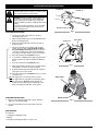
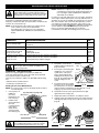
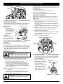
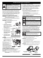
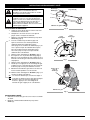
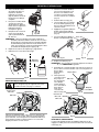
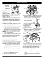
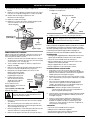
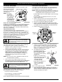
KNOW YOUR UNIT
Muffler
TB525CS &
TB575SS
D-Handle
Oil Fill Plug
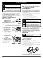
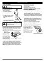
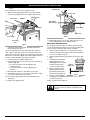
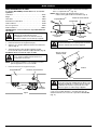
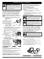
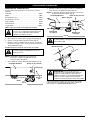
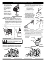
INSTALLING AND ADJUSTING THE D-HANDLE
If your unit has the D-Handle pre-installed, please follow the
“To Adjust” instructions only.
(4) Screws
D-Handle
To Install
1. Remove the screws and
bottom clamp piece that
were installed on the Dhandle for shipping.
Fuel
Cap
Shaft Grip
On/Off Stop
Control
ASSEMBLY INSTRUCTIONS
Spark
Plug
Choke
Lever
Starter
Rope
Grip
2.
Throttle
Control
Air Filter
Cover
Click Link
Primer
Bulb
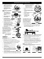
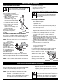
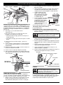
Place the D-handle over Minimum
6 inches
the shaft housing and
(15.24 cm)
onto the bottom clamp
(Fig. 1). Place it a
minimum of 15.24 cm (6
in) from the end of the
shaft grip.
Bottom
Clamp
Fig. 1
3.
Start screws with a large Flat-head or T-25 Torx
screwdriver. Do not tighten until you make the handle
adjustment.
To Adjust
4. If the D-handle was pre-installed, loosen the screws on the
handle just enough to move it.
Shaft
Line
Cutting
Blade
Cutting
Attachment Shield
Cutting
Attachment
3
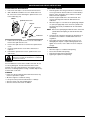
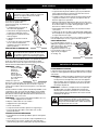
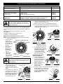
5.
While holding the unit in the operating position, manuever
the D-handle to the location that provides you the best grip
(Fig. 12).
6.
Tighten the clamp screws evenly, until the D-handle is
secure.