1
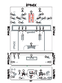
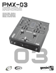
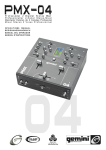
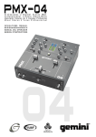
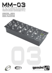
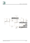
Professional 2 Channel Stereo Mixer
P r o f e s s i o n e l l e r 2 - K a n a l St e r e o - M i x e r
Mezclador Estereo de 2 Canales Profesional
M i x e r St e r e o 2 Vo i e s P r o f e s s i o n n e l
OPERATIONS MANUAL
BEDIENUNGSHANDBUCH
MANUAL DEL OPERADOR
MANUEL D’INSTRUCTIONS
MULTI LANGUAGE INSTRUCTIONS
ENGLISH..........................................................................................................................................................................................................................PAGE 4
DEUTSCH.............................................................................................................................................................................................................................PAGE 6
ESPAÑOL.............................................................................................................................................................................................................................PAGE 8
FRANCAIS.............................................................................................................................................................................................................................PAGE 10
PLEASE READ BEFORE USING APPLIANCE, IMPORTANT WARNING & SAFETY INSTRUCTIONS!
CAUTION
RISK OF ELECTRICAL SHOCK DO NOT OPEN!
CAUTION: This product satisfies FCC regulations when shielded cables and connectors are used to
connect the unit to other equipment. To prevent electromagnetic interference with electric appli
ances such as radios and televisions, use shielded cables and connectors for connections.
The exclamation point within an equilateral triangle is intended to alert the user to the presence of
important operating and maintenance (servicing) instructions in the literature accompanying the
appliance.
The lightning flash with arrowhead symbol, within an equilateral triangle, is intended to alert the
user to the presence of uninsulated “dangerous voltage” within the product’s enclosure that may
be of sufficient magnitude to constitute a risk of electric shock to persons.
READ INSTRUCTIONS: All the safety and operating instructions should be read before
the product is operated.
RETAIN INSTRUCTIONS: The safety and operating instructions should be retained for
future reference.
HEED WARNINGS: All warnings on the product and in the operating instructions should
be adhered to.
FOLLOW INSTRUCTIONS: All operating and use instructions should be followed.
OUTDOOR ANTENNA GROUNDING: If an outside antenna or cable system is
connected to the product, be sure the antenna or cable system is grounded so as to
provide some protection against voltage surges and built-up static charges. Article
810 of the National Electrical Code, ANSI/NFPA 70, provides information with
regard to proper grounding of the mast and supporting structure, grounding of the
lead-in wire to an antenna discharge unit, size of grounding conductors, location of
antenna-discharge unit, connection to grounding electrodes, and requirements for
the grounding electrode. See Figure B.
LIGHTNING: For added protection for this product during a lightning storm, or when it
is left unattended and unused for long periods of time, unplug it from the wall outlet
and disconnect the antenna or cable system. This will prevent damage to the
product due to lightning and power-line surges.
POWER LINES: An outside antenna system should not be located in the vicinity of
overhead power lines or other electric light or power circuits, or where it can fall into
such power lines or circuits. When installing an outside antenna system, extreme
care should be taken to keep from touching such power lines or circuits as contact
with them might be fatal.
CLEANING: The product should be cleaned only with a polishing cloth or a soft dry
cloth. Never clean with furniture wax, benzine, insecticides or other volatile liquids
since they may corrode the cabinet.
OVERLOADING: Do not overload wall outlets, extension cords, or integral convenience
receptacles as this can result in a risk of fire or electric shock.
ATTACHMENTS: Do not use attachments not recommended by the product manufac
turer as they may cause hazards.
OBJECT AND LIQUID ENTRY: Never push objects of any kind into this product through
openings as they may touch dangerous voltage points or short-out parts that could
result in a fire or electric shock. Never spill liquid of any kind on the product.
WATER AND MOISTURE: Do not use this product near water, for example, near a bath
tub, wash bowl, kitchen sink, or laundry tub; in a wet basement; or near a swimming
pool; and the like.
ACCESSORIES: Do not place this product on an unstable cart, stand, tripod, bracket,
or table. The product may fall, causing serious injury to a child or adult, and serious
damage to the product. Use only with a cart, stand, tripod, bracket, or table recom
mended by the manufacturer, or sold with the product. Any mounting of the product
should follow the manufacturer’s instructions, and should use a mounting accessory
recommended by the manufacturer.
CART: A product and cart combination should be moved with care. Quick stops, exces
sive force, and uneven surfaces may cause the product and cart combination to over
turn. See Figure A.
VENTILATION: Slots and openings in the cabinet are provided for ventilation and to
ensure reliable operation of the product and to protect it from overheating, and
these openings must not be blocked or covered. The openings should never be
blocked by placing the product on a bed, sofa, rug, or other similar surface. This
product should not be placed in a built-in installation such as a bookcase or rack
unless proper ventilation is provided or the manufacturer’s instructions have been
adhered to.
POWER SOURCES: This product should be operated only from the type of power
source indicated on the marking label. If you are not sure of the type of power sup
ply to your home, consult your product dealer or local power company.
LOCATION: The appliance should be installed in a stable location.
NON-USE PERIODS: The power cord of the appliance should be unplugged from the
outlet when left unused for a long period of time.
GROUNDING OR POLARIZATION:
•
If this product is equipped with a polarized alternating current line plug (a plug
having one blade wider than the other), it will fit into the outlet only one way. This is
a safety feature. If you are unable to insert the plug fully into the outlet, try
reversing the plug. If the plug should still fail to fit, contact your electrician to
replace your obsolete outlet. Do not defeat the safety purpose of the polarized plug.
•
If this product is equipped with a three-wire grounding type plug, a plug having a
third (grounding) pin, it will only fit into a grounding type power outlet. This is a
safety feature. If you are unable to insert the plug into the outlet, contact your
electrician to replace your obsolete outlet. Do not defeat the safety purpose of the
grounding type plug.
POWER-CORD PROTECTION: Power-supply cords should be routed so that they are
not likely to be walked on or pinched by items placed upon or against them, paying
particular attention to cords at plugs, convenience receptacles, and the point where
they exit from the product.
SERVICING: Do not attempt to service this product yourself as opening or removing
covers may expose you to dangerous voltage or other hazards. Refer all servicing
to qualified service personnel.
DAMAGE REQUIRING SERVICE: Unplug this product from the wall outlet and refer
servicing to qualified service personnel under the following conditions:
•
When the power-supply cord or plug is damaged.
•
If liquid has been spilled, or objects have fallen into the product.
•
If the product has been exposed to rain or water.
•
If the product does not operate normally by following the operating instructions.
Adjust only those controls that are covered by the operating instructions as an
improper adjustment of other controls may result in damage and will often require
extensive work by a qualified technician to restore the product to its normal operation.
•
If the product has been dropped or damaged in any way.
•
When the product exhibits a distinct change in performance, this indicates a need for
service.
REPLACEMENT PARTS: When replacement parts are required, be sure the service
technician has used replacement parts specified by the manufacturer or have the
same characteristics as the original part. Unauthorized substitutions may result in
fire, electric shock, or other hazards.
SAFETY CHECK: Upon completion of any service or repairs to this product, ask the
service technician to perform safety checks to determine that the product is in
proper operating condition.
WALL OR CEILING MOUNTING: The product should not be mounted to a wall or ceil
ing.
HEAT: The product should be situated away from heat sources such as radiators, heat
registers, stoves, or other products (including amplifiers) that produce heat.
(2)
Fig. B
(3)
INTRODUCTION:
Congratulations on your purchase of a GEMINI iPMX 10" 2
Channel Stereo Mixer. This state-of-the-art mixer features
the latest technological advances and is backed by a three
year warranty, excluding the crossfader and channel slides.
FEATURES:
- 10" 2 stereo channel mixer
- 4 line, 2 convertible phono/line, RCA inputs
- 3 band rotary line EQ with cut feature
- EQ Kill Switches w/ Flash Effect
- Easy removable face plate for user replaceable Rail Glide
Cross Fader
- Ergonomically designed to be flush with turntable
- Smooth curved face plate
- Front located Hamster/Reverse & crossfader Curve control switches
- Rotary Gain channel control
- Dual display with Bright LED
- Front located rotary Cue volume control & Cue section
fader allowing Cue mix
- Face plate located 2 band rotary Mic EQ & volume controls
- Front located 1/4" Mic input & headphone output
- Dual ground screws for easy connectivity
- Master and record RCA outputs
3. Headphones may be plugged into the front panel-mounted HEADPHONES (8) ¼" jack.
4. Microphones may be plugged into the front panel-mounted MICROPHONE (10) ¼" jack.
5. The iPMX has 2 CONVERTIBLE PHONO/LINE RCA
INPUTS (6,27) located on the back panel on either side of
the RCA INPUTS. Facing the back panel, the convertible
RCA Input on your right is for PHONO 1/ LINE 1 (27). The
convertible RCA input on your left is for PHONO 2/ LINE 3
(6). Using the PHONO/ LINE SWITCHES (4,26), located
just below each input, you may convert the PHONO to
LINE and vice versa. Plug the RCA's from your playable
medium into each input to be connected to their respective
CHANNELS (19,31). The PHONO INPUTS (6,27)only
accept turntables with a magnetic cartridge. The STEREO
LINE INPUTS (6,7,27,28) only accept line level inputs such
as a CD, DAT, MiniDisc, etc and require the proper switch
setting.
6. When using (a) turntable(s), you will need to ground the
RCA cable(s) by screwing in the grounding fork(s) to the
GROUNDING SCREWS (5,29)located in the back panel of
the iPMX mixer. Attach each PHONO ground line to one of
the DUAL GROUND THUMB SCREWS (5,29). These are
adjacent to each RCA INPUT (6,7,27,28).
NOTE: Not attaching a ground may cause a system "hum."
CAUTIONS:
1. All instructions should be read before using this equipment.
2. To reduce the risk of electrical shock, do not open the
unit. Please refer all servicing needs to a Gemini-qualified
service technician.
In the USA ~ if you experience problems with this unit call
Gemini Customer Service at: 1 (732) 738-9003. Do not attempt to
return this equipment to your dealer.
3. Do not expose this unit to direct sunlight or a heat source
such as a radiator or stove.
4. This unit should be cleaned only with a damp cloth. Avoid
solvents or other cleaning detergents.
5. When moving this equipment it should be placed in its
original carton and packaging. This will reduce the risk of
damage during transit.
6. DO NOT EXPOSE THIS UNIT TO RAIN OR MOISTURE.
7. DO NOT USE SPRAY CLEANERS OR LUBRICANTS
ON CONTROLS, SURFACES OR SWITCHES.
CONNECTIONS:
OPERATION:
1. POWER ON: Once all equipment connections have
been made, press POWER (1) switch. Power is ON when
the VU METER (25) power LEDs are illuminated.
2. CHANNEL 1: The GAIN (24), HIGH (23), MID (22), and
LOW (21) controls allow you to fully adjust the selected
source. The PH-1/LN-1 (26) switch located on the rear
panel allows you to select PHONO 1 or LINE 1. The
PHONO1/LINE1-LINE 2 (17) switch located on the front
allows you to switch from PHONO 1 to LINE 2 or LINE 1 to
LINE 2. CHANNEL 1 SLIDE (19) controls the input level of
this channel.
3. CHANNEL 2: The GAIN (32), HIGH (33), MID (34), and
LOW (35) controls allow you to fully adjust the selected
source. The PH-2/LN-3 (4) switch a located on the rear
panel allows you to select PHONO 2 or LINE 3. The
PHONO2/LINE3-LINE 4 (30) switch located on the front
allows you to switch from PHONO 2 to LINE 4 or LINE 3 to
LINE 4. CHANNEL 2 SLIDE (31) controls the input level of
this channel.
1. Ensure that the POWER (1) switch is in the OFF position
prior to making any connections. This unit comes with a
15V AC (2) adapter. Plug into the rear panel 15V AC (2)
jack before plugging it into a proper power source.
PLEASE NOTE: There is Low, Mid and High equalization for each
channel with an extremely wide range of adjustment.
2. The iPMX has 2 sets of outputs:
4. KILLING FREQUENCIES: There are two ways to kill frequencies, using the LOW (38), MID (37), and HIGH (36)
KILL SWITCHES. Each Kill Switch has three positions,
latch, normal and flash. When you move the selected KILL
SWITCH to the top LATCH (ON) position, the switch will
stay there, and the frequency will be killed. When you move
the selected KILL SWITCH to the center position the kill
function is not active and the frequency will not be killed.
- The MASTER OUTPUT (3) jacks also connect to the
main amplifier with RCA cables.
- The REC OUTPUT (39) jacks can be used to connect the
mixer to the record input of your recording unit, thus
enabling you to record your mix by connecting these units
with RCA cables.
(4
4)
SUGGESTION: You can use the Cut Features on each channel to
remove Low, Mid and/or High range to create special effects.
When you move the selected KILL SWITCH to the bottom
FLASH position and hold it there, the frequency will be
killed. Releasing the selected KILL SWITCH from the bottom position will bring it back to the center position and the
frequency will no longer be killed.
5. CROSSFADER SECTION: The CROSSFADER (20)
allows the mixing of one source into another. The left side
of the CROSSFADER (20) is CH 1 (19) while the right
belongs to CH 2 (31). You may also reverse this default by
switching the HAMSTER/REVERSE (11) switch. The
CROSSFADER (20) in your unit is removable and if the
need arises can be easily replaced. Your Gemini mixer
comes with an RG-45 (RAILGLIDE™) DUAL-RAIL
CROSSFADER. RAIL GLIDE™ crossfaders have internal
dual stainless steel rails that allow the slider to ride smoothly and accurately from end to end. Also available is our is
the RG-45 PRO (RAIL GLIDE™) crossfader with a special
curve designed for scratch mixing. Just purchase one from
your GEMINI dealer and follow the instructions:
8. CUE: Cue facilitates the seamless blending of one
recorded track into another. Connecting a set of headphones to the HEADPHONES (8) jack allows you to monitor either CHANNEL 1 or CHANNEL 2. Select CHANNEL
1 (19) by moving CUE FADER (18), located on the front
panel, to CUE 1 on the left. Listen to CHANNEL 2 by moving CUE FADER (18) to CUE 2 on the right. To mix both
Channels bring CUE (18) to the middle so that both tracks
may be heard. Use CUE VOLUME (9) to adjust the headphone volume without affecting the speaker-driven mix.
9. MIC SECTION: Connecting a microphone to the 1/4"
MIC JACK (10) allows voice amplification through the
mixer to the stereo through the MASTER OUTPUTS (3).
This is controlled by the MIC VOLUME (16), HIGH (15),
LOW (14) rotary controls.
10. OUTPUT CONTROL SECTION: The level of the MASTER OUTPUT (3) is controlled by the MASTER VOLUME
(13) rotary control.
11. DISPLAYS: The DUAL LED METER (25) indicates the
MASTER OUTPUT (3) in stereo. DUAL LED METER (25)
reflects the MASTER VOLUME (13), GAIN (24,32), HIGH
(23, 33), MID (22, 34) and LOW (21, 35) rotary control
adjustments for each channel. The CHANNNEL SLIDES
(19, 31) also affect each of the LED METER (25) LEDs.
USER REPLACEABLE CROSS FADER
1. Unscrew the outside mixer
FACE PLATE screws and
remove the face plate. Then
remove FADER plate screws (B
& C).
2. Carefully lift the fader and
unplug the CABLE (D).
3. Plug the new fader into the
cable and place it back in the
mixer.
4. Screw fader plate to the mixer
and replace the mixer FACE
PLATE.
SPECIFICATIONS:
INPUTS:
DJ Mic......................................................................1.5 mV 1 kOhm Balanced
Phono........................................................................................3 mV 47 kOhm
Line.......................................................................................150 mV 10 kOhm
OUTPUTS:
Note: Do not apply pressure while using the Crossfader. Lightly glide
the Crossfader back and forth. Pressing down on the controls can
bend contacts and cause a loss of sound.
6. CURVE CONTROL: The CROSSFADER CURVE
SWITCH (12) allows you to adjust the kind of curve the
crossfader has. Depress the crossfader curve button to
make the curve steep and cutting (perfect for scratching).
Release the crossfader curve button to make the curve
gradual and gentle.
7. HAMSTER CONTROL: The CROSSFADER REVERSE
SWITCH (11) allows you to reverse the crossfader so that
CHANNEL 2 (31) is controlled by the left side of the crossfader and CHANNEL 1 (19) is controlled by the right side of
the crossfader.
NOTE: When the CROSSFADER REVERSE SWITCH (11) is activated
(moved to the right), only the crossfader reverses. The Channel
Slides, Gain, Kill Switches and tonal controls do not reverse.
(5)
Amp........................................... ..........................................0 dB 1V 400 Ohm
Max.......................................................................................20V Peak to Peak
GENERAL:
Bass (Channels 1-2)..................................................................+12 dB/-36 dB
Mid (Channels 1-2).....................................................................+12 dB/-36 dB
High (Channels 1-2)...................................................................+12 dB/-36 dB
Gain (Channels 1-2)........................................................................0 to -20 dB
Frequency Response....................................................20 Hz-20 kHz +/- 2 dB
Distortion...............................................................................Less Than 0.02%
S/N Ratio.............................................................................Better Than 80 dB
Headphone Impedance........................................................................32 Ohm
Power Source Adapter........................................................115V/15V AC 0.5A
........................................................................................or 230V/15V AC 0.5A
Unit Dimensions........................................................W 10" x H 3.3" x D 10.25"
..........................................................................................(254 x 84 x 260mm)
Weight....................................................................................6.2 lbs ( 2.81 kg)
NOTE: SPECIFICATIONS AND DESIGN ARE SUBJECT TO CHANGE
WITHOUT NOTICE FOR PURPOSE OF IMPROVEMENT.
EINLEITUNG:
Wir gratulieren Ihnen zum Kauf eines GEMINI iPMX
MISCHPULTS. Dieses moderne Mischpult ist nach dem
neuesten Stand der Technik hergestellt und mit dreijähriger
Garantie, ausschließlich Crossfader und Kanalfader, ausgestattet. Vor Anwendung dieses Mischpults bitte alle
Anweisungen sorgfältig durchlesen.
FUNKTIONEN:
- 10" 2-Kanal-Stereo-Mixer
- 4 Line, 2-umschaltbare Phono/Line Cincheingänge
- 3 Band-EQ mit Cutfunktion und Drehreglern
- EQ-Kill-Schalter mit Flash-Effekt
- Einfach auszutauschender Rail-Glide-Crossfader
- Ergonomisches Design
- Abgerundete Frontplatte
- Schalter für X-Fader-Reverse und Kurveneinstellung auf
der Vorderseite
- Gaindrehregler pro Kanal
- Zweifach-Display-Anzeige mit LED
- Cuesektion mit Volumedrehregler und Cue-Mix-Fader auf
der Vorderseite
- Volume- und Eq-Drehregler für Mikrofon auf der
Frontplatte
- 6.3 mm Klinkenbuchse für Kopfhörer auf der Vorderseite
- 2 Erdungsschrauben für Masseanschluß
- Master und record cinchausgänge
VORSICHTSMAßNAHMEN
1. Vor Anwendung dieses Geräts bitte alle Anweisungen
sorgfältig durchlesen.
2. Das Gerät nicht öffnen, um das Risiko elektrischen
Schocks zu vermeiden. Die Wartung darf nur von
befähigten Wartungstechnikern durchgeführt werden.
3. Das Gerät nicht direktem Sonnenlicht oder einer
Wärmequelle wie Heizkörper oder Ofen aussetzen.
4. Dieses Gerät darf nur mit einem feuchten Tuch gesäubert werden. Keine Lösungs- oder Reinigungsmittel
benutzen.
5. Bei Umzügen sollte das Gerät in seinem ursprünglichen
Versandkarton und Verpackungsmaterial verpackt werden.
Dadurch verhindert man, daß das Gerät während des
Transportes beschädigt wird.
6. DIESES GERÄT NICHT REGEN ODERFEUCHTIGKEIT
AUSSETZEN.
7. AN DEN REGLERN ODER SCHALTERN KEIN SPRAYREINIGUNGSMITTEL
ODER
SCHMIERMITTEL
BENUTZEN.
SONST
ERLISCHT
DER
GARANTIEANSPRUCH.
ANSCHLÜSSE:
1. Vor dem Einstecken des 15V ADAPTER (2) in die
Buchse: POWER (1) auf Rückseite, überprüfen Sie, ob der
15V ADAPTER (2) Schalter ausgeschaltet ist.
2. El iPMX tiene 2 salidas:
- SALIDA MASTER (3) también conecta el mezclador con
el amplificador principal, pero con conectores RCA.
(6)
- SALIDA DE GRABACIÓN (39) puede ser utilizada para
conectar con cables RCA el mezclador a una entrada de
un dsipositivo de grabación, así como permitir grabar tu
propia sesión.
3. Kopfhörer können an der Vorderseite in die
KOPFHÖRER-BUCHSE HEADPHONE (8) eingesteckt
werden.
4. Der Eingang DJ MIC (10) (an der Vorderseite) dient zum
Anschluß eines Mikrofons mit 6.3 mm Klinkenstecker (symmetrisch oder unsymmetrisch).
5. An der Rückseite sind jeweils 2 STEREOEINGÄNGE
PHONO/LINE (6, 27) und 2 Stereoeingänge LINE (7, 28)
angebracht. Die Schalter PHONO/LINE SWITCHES (4, 26)
ermöglichen Ihnen, die EINGÄNGE (6, 27) zwischen
Phono und Line umzuschalten. An die Phono-Eingänge
können nur Plattenspieler mit einem magnetischem
Tonabnehmer angeschlossen werden.
6. Zwei Erdungschrauben DUAL GROUND SCREWS (5,
29) zur Erdung des Plattenspielers sind an der Rückseite
angebracht. An die Stereo-Lineeingänge können Geräte
wie CD- oder Kassettenspieler angeschlossen werden.
ANMERKUNG: WENN DIE ERDUNG NICHT ANGESCHLOSSEN WIRD
KANN EIN BRUMMSIGNAL AUFTRETEN.
BEDIENUNG
1. STROM EIN: Nachdem Sie alle Geräte am Mischpult
angeschlossen haben, stecken Sie das Steckernetzteil in
eine Schukosteckdose(230V)und drücken Sie auf die Taste
POWER (1). Die Aussteuerungsanzeige VU-METER
(25)leuchtet auf.
2. KANAL 1: Die EQ-Regler GAIN (24), HIGH (23), MID
(22), LOW (21) dienen zur Anhebung /Absenkung der
Höhen, Mitten und Tiefen. Der GAIN (24)-Regler erlaubt
Ihnen, die Signalstärke des Kanals individuell zu regulieren. SCHALTER (17) ermöglicht, den Eingang von
PHONO 1/LINE 1 (27) oder LINE 2 (28) auszuwählen.
CHANNEL
SLIDE
(19)
(Kanalfader)regelt
den
Ausgangspegel dieses Kanals.
3. KANAL 2: Die EQ-Regler GAIN (32), HIGH (33), MID
(34), LOW (35) dienen zur Anhebung /Absenkung der
Höhen, Mitten und Tiefen. Der GAIN (32)-Regler erlaubt
Ihnen, die Signalstärke des Kanals individuell zu regulieren. SCHALTER (30) ermöglicht, den Eingang von
PHONO 2/LINE 3 (6) oder LINE 4 (7) auszuwählen. CHANNEL SLIDE (31) (Kanalfader) regelt den Ausgangspegel
dieses Kanals.
Hinweis: Zur individuellen Klangregelung, ist jeder Kanal mit einem
3-Band EQ ausgestattet. Dadurch ist eine Klangveränderung in weiten Bereichen möglich.
4. KILL SEKTION: Es gibt zwei Möglichkeiten, Frequenzen
ganz auszublenden, indem man die Schalter LOW (38),
MID (37) und HIGH (36) drückt. Jeder KILL SWITCH hat
drei Positionen: Latch, Normal und Flash. Wenn der ausgewählte KILL SWITCH ganz nach oben in die LatchPosition (ON) geschoben wird, bleibt der Schalter in dieser
Position, und die Frequenz wird ausgeblendet. Wird der
ausgewählte KILL SWITCH in die mittlere Position
geschoben, ist die Kill-Funktion nicht aktiv. Wird der aus-
gewählte KILL SWITCH in die untere Flash-Position
geschoben und dort gehalten, wird die Frequenz ausgeblendet. Wird der ausgewählte KILL SWITCH wieder losgelassen, federt er in die mittlere Position zurück, und die
Frequenz wird nicht mehr ausgeblendet.
9. MIC SECTION: Ein Mikrophon bis das erlaubt 1/4" MIC
JACK (10) anschließend,Sprachverstärkung durch den
Mischer zum Stereo durch dieVorlagenausgänge. Dieses
wird durch die Drehsteuerungs des HIGH (15), LOW (14)
VOLUMENS MIC (16) gesteuert.
Ratschlag: Sie können die CUT Funktion und die Kill-Features eine
jeden Kanals benutzen, um Low, Mid und/oder High auszublenden
um dadurch Spezialeffekte zu erzielen.
10. CUE: Indem Sie die Kopfhörer an der KOPFHÖRERBUCHSE (8) anschließen, können Sie einen oder beide
Kanäle zusammen überwachen. Den CUE-SCHALTER
(18) nach links schieben, um KANAL 1 (19) zu
überwachen. Den CUE-SCHALTER (18) nach rechts
schieben, um KANAL 2 (31) zu überwachen. Mit Hilfe des
CUE-PEGEL-REGLERS (9) kann die Kopfhörerlautstärke
eingestellt werden, ohne dabei die allgemeine
Tonmischung zu beeinträchtigen.
5. CROSSFADER SEKTION (ÜBERBLENDER): Der
CROSSFADER (20) ermöglicht das Mixen von einem
Kanal zum Anderen. Der iPMX ist mit einem RG-45 (RAILGLIDE™) DUAL-RAIL Crossfader ausgestattet, welcher
im Servicefall leicht austauschbar ist. RAIL GLIDE™
CROSSFADER sind mit Doppel-Edelstahlschienen ausgestattet, die ein sanftes Gleiten zwischen beiden
Endpunkten ermöglichen. Lieferbar ist ausserdem der RG45 PRO (PROGLIDE™), der speziell für das Scratchen
designed wurde:
11. VU METER: Die Doppelfunktionsanzeige VU METER
(25) gibt eine Darstellung entweder der Pegel des MASTER RCA OUTPUT-(13) Ausgangs links und rechts oder
der Pegel der Kanäle 1 und 2. Die gewünschte Option kann
durch Druck auf die Taste VU METER (25) gewählt werden.
EINFACH AUSZUTAUSCHENDER RAIL-GLIDE-CROSSFADER
1. Die äußeren SCHRAUBEN DER
CROSSFADERPLATTE (B) losschrauben. Nicht die INNENSCHRAUBEN (C) losschrauben.
2. Den Überblender vorsichtig
anheben und das KABEL (D)
abziehen.
3. Das Kabel an den neuen
Crossfader stecken und wieder in das
Mischpult setzen.
4. Den neuen Überblender mit den
Schrauben am Mischpult befestigen.
Zu beachten: Wenn das DISPLAY (25) sich im Anzeigemodus Kanal
1/Kanal 2 befindet, kann das Signal mittels der jeweiligen Gainregler
verstärkt oder verringert werden, um es dem Signal des anderen
Kanals anzupassen. Die Kanalfader und der Crossfader haben
keinen Einfluß auf die Anzeigewerte.
SPEZIFIKATIONEN:
EINGÄNGE:
6. Die CROSSFADER CURVE-TASTE (12) ermöglicht die
jeweilige Art der Kurve des Crossfaders einzustellen.
Drücken Sie auf die Crossfader Curve-Taste um die Kurve
steil und scharf zu machen (ideal für Scratchen). Lösen Sie
die Crossfader Curve-Taste aus um die Kurve sanft und
weich zu machen.
7. Der CROSSFADER REVERSE SWITCH (11) ermöglicht
die Umkehrfunktion des Crossfaders KANAL 2 (31) wird
nun kontrolliert durch die linke Seite des Crossfader und
KANAL 1 (19) durch die rechte Seite.
HINWEIS: Ist der CROSSFADER REVERSE-SCHALTER (11) aktiviert
(nach rechts geschoben), läuft nur der Crossfader gegenläufig. Die
Kanalfader und alle anderen Drehregler und Schaltern nicht!
8. AUSGANGSREGELUNG: Der Pegel des MASTER
OUTPUT (3) (Verstärkerausgang) wird mittels des
Drehreglers MASTER (13) gesteuert.
DJ-Mikrophon...................................1.5 mV 1 kOhm balanced
Phono...............................................................3 mV, 47 kOhm
Line..............................................................150 mV, 10 kOhm
AUSGÄNGE:
Verstärker....................................................0 dB 1 V 400 Ohm
Max..............................................................20V Spitze-Spitze
ALLGEMEINES:
Tiefenregler (Kanäle 1 - 2)...................................+12dB/-36dB
Mittenregler (Kanäle 1 - 2)...................................+12dB/-36dB
Höhenregler (Kanäle 1 - 2)..................................+12dB/-36dB
Gainregler (Kanäle 1 - 2)......................................0 bis -20 dB
Frequenzgang....................................20 Hz - 20 kHz +/- 2 dB
Klirrfaktor.....................................................................< 0.02%
Störabstand....................................................besser als 80 dB
Kopfhörerimpedanz.....................................................32 Ohm
Stromversorgung...............Steckernetzteil 230V/15V AC 0.5A
Abmessungen............................................254 x 84 x 260 mm
Gewicht.........................................................................2.81 kg
DIE
SPEZIFIKATIONEN
KÖNNEN
ZU
VERBESSERUNGSZWECKEN
OHNE
VORHERIGE
BEKANNTGABE GEÄN DERT WERDEN.
(7
7)
INTRODUCCIÓN
Felicitaciones por su compra del mezclador iPMX de
GEMINI. Este mezclador de la más avanzada tecnología
está dotado de características ultramodernas y está respaldado por una garantía de tres años, salvo el crossfader y
los faders de canal. Antes de usarlo, le recomendamos leer
cuidadosamente todas las instrucciones.
CARACTERÍSTICAS
- Mezclador Estéreo 10" de 2 canales
- Entradas RCA 4 Línea, 2 convertibles Phono/Línea
- EQ rotativo de 3 Bandas con sistema Cut
- Interruptor Kill con efecto Flash
- Carátula fácilmente removible para cambiar el Crossfader
por parte del usuario
- Diseño ergonómico para encajar con los giradiscos
- Carátula curvada suavemente
- Hamster/Reverse & Control de curva del Cross Fader en
frontal
- Control de Ganancia rotativo
- Doble Display con LED
- Volumen Cue rotativo y Fader de Cue en panel frontal con
Cue Mix
- EQ rotativo de 2 bandas para micrófono en panel principal
- Salida auriculares y entrada micrófono jack ¼" en panel
frontal
- Doble toma de tierra para fácil conexión
- Salida RCA para master y grabación
PRECAUCIONES
1. Deberán leerse todas las instrucciones de operación
antes de usar el equipo.
2. Para reducir el riesgo de shock eléctrico, no abra esta
unidad. Por favor, refiera el servicio a un técnico de servicio calificado.
3. No exponga la unidad a la luz solar directa ni a una
fuente de calor, por ejemplo, un radiador o estufa.
4. Esta unidad sólo deberá limpiarse con un paño húmedo.
Evite el uso de disolventes u otros detergentes de limpieza.
5. Para mover este equipo, colóquelo en la caja y embalaje original, a fin de reducir el riesgo de daños durante el
transporte.
6. NO DEJE ESTA UNIDAD EXPUESTA A LLUVIA O
HUMEDAD.
7. NO USE LIMPIADORES DE SPRAY O LUBRICANTES
EN CUALESQUIER CONTROLES O INTERRUPTORES.
CONEXIONES
1. Antes de enchufar el ADAPTADOR de la CA 15V en la
alimentación POWER JACK (2) en panel trasero, cerciórese de que el interruptor de la ALIMENTACION POWER (1) está en la posición de reposo.
2. El iPMX tiene 2 salidas:
- SALIDA MASTER (3) también conecta el mezclador con
el amplificador principal, pero con conectores RCA.
(8)
- SALIDA DE GRABACIÓN (39) puede ser utilizada para
conectar con cables RCA el mezclador a una entrada de
un dsipositivo de grabación, así como permitir grabar tu
propia sesión.
3. Los auriculares se enchufan en el jack de HEADPHONE
(8) (auriculares) montado en el panel delantero.
4. La entrada DJ MIC (10) (que se encuentra en el panel
delantero) acepta conector de jack ¼" y micrófonos balanceados y no balanceados.
5. En el panel trasero hay 2 entradas estereofónicas
PHONO/LÍNEA - PHONO/LINE (6, 27), y 2 entradas
estereofónica de LÍNEA - LINE (7, 28). Los conmutadores
PHONO/LINE SWITCHES (4,26) le permiten conmutar las
ENTRADAS (6, 27) a Phono o Line (giradiscos o línea).
Las entradas phonp solamente aceptarán giradiscos con
cápsula magnética.
6. Un GROUND SCREW (5, 29) para poner el giradiscos a
tierra se encuentra en el panel trasero. Las entradas de
línea estereofónicas aceptarán cualquier entrada de nivel
de línea tal como reproductor de discos compactos o cintas, etc.
NOTA: Al conectar una masa puede causar ruidos.
FUNCIONAMIENTO
1. ENCENDIDO: Una vez que haya efectuado todas las
conexiones de los equipos a su mezclador, oprima el
INTERRUPTOR DE ALIMENTACIÓN - POWER (1).
2. CANAL 1: Los mandos de GAIN (24) (ganancia), HIGH
(23) (alto), MID (22) (medios) y LOW (21) (bajo) le permiten
ecualizar la fuente seleccionada. El SWITCH # (17) le permite seleccionar la entrada LINE 2 (28) o PHONO 1/LINE
1 (27). El CHANNEL SLIDE (19) (fader de canal) controla
el volumen de salida de este canal.
3. CANAL 2: Los mandos de GAIN (32) (ganancia), HIGH
(33) (alto), MID (34) (medios) y LOW (35) (bajo) le permiten
ecualizar la fuente seleccionada. El SWITCH # (30) le permite seleccionar la entrada PHONO 2/LINE 3 (6), o LINE 4
(7). El CHANNEL SLIDE (31) (fader de canal) controla el
volumen de salida de este canal.
NOTA: La ecualización de graves, medios y agudos por cada canal
con muy amplio espectro le permite obtener mejor mezcla.
4. SUPRESION DE FRECUENCIAS: Hay dos maneras
para suprimir frecuencias: mediante los LOW (38), MID
(37) y HIGH (36) KILL SWITCHES (interruptores de supresión de frecuencias bajas, medianas y altas). Cada interruptor de supresión puede ocupar tres posiciones: latch
(enganche), normal y flash (destello). Cuando el KILL
SWITCH seleccionado ocupa la posición superior de
"latch" (ON), el interruptor se mantendrá en este sitio y la
frecuencia será suprimida. Cuando el KILL SWITCH seleccionado ocupa la posición central, la función de supresión
no es activa y la frecuencia no será suprimida. Cuando el
KILL SWITCH seleccionado ocupa la posición inferior de
"flash" y se mantiene en este sitio, la frecuencia será
suprimida. Cuando se libera el KILL SWITCH seleccionado de la posición inferior, volverá a la posición central y la
frecuencia ya no se suprimirá.
SUGERENCIA: Puede usar las funciones CUT y las funciones de
supresión en cada canal para suprimir los tonos bajos, medianos y/o
altos para crear efectos especiales.
5. SECCIÓN CROSS FADER: El CROSS FADER (20) permite mezclar de una fuente a otra. El CROSS FADER (20)
en su unidad es reemplazable y si se necesita, de fácil
intercambio. Su mezclador GEMINI viene con un cross
fader RG-45 (RAILGLIDE™) Doble-Rail. Rail Glide™
cross fader tienen dos raíles internos de acero inoxidable
que permite un deslizamiento suave y preciso de un
extreme al otro. También tiene disponible el RG-45 PRO
(PROGLIDE™) Doble-Rail. Este crossfader de características únicas, tiene una curva especialmente diseñada para
scratch. Simplemente compre uno en su distribuidor habitual y sigua estas instrucciones:
CAMBIAR EL CROSSFADER POR PARTE DEL USUARIO
1. Destornille los TORNILLOS EXTERIORES de la
PLACA DEL CROSSFADER
(B). No toque LOS TORNILLOS INTERIORES (C).
2. Levante cuidadosamente
el crossfader y desenchufe el
CABLE (D).
3. Conecte el nuevo crossfader al cable y póngalo de
nuevo dentro del mezclador.
4. Atornille el crossfader en el
mezclador.
9. SECCION DE MIC: Conectar un micrófono con los 1/4"
MIC GATO (10) permite la amplificación de la voz a través
del mezclador ala estereofonia a través del amo Salidas.
Esto es controlada por los controles rotatorios del VOLUMEN MIC (16), HIGH (15) (altos), y LOW (14) (bajos).
10. SECCIÓN CUE (DE PREESCUCHA): Al conectar
auriculares al jack de HEADPHONE (8), se puede monitorear el canal 1, el canal 2 o ambos a la vez. Mueva el
CUE FADER (18) a la izquierda para monitorear el CANAL
1 (19). Mueva el CUE FADER (18) a la derecha para monitorear el CANAL 2 (31). Utilice el mando del - (9) para
ajustar el volumen del auricular sin afectar la mezcla global.
11. VU METRO: El VU METRO (25), de doble función, indica ya sea los niveles de salida principal izquierda y
derecha RCA de MASTER OUTPUT (13) o los niveles del
canal 1 y del canal 2. Se puede elegir la opción apretando
el botón de visualizador VU METRO (25).
Nota: Cuando el visualizador DISPLAY (25) está en modalidad de
canal 1/canal 2, se puede aumentar o disminuir la señal para igualarla a la señal del otro canal graduando los controles de ganancia de
cada canal. Los faders de canal y el crossfader no tienen efecto
sobre la lectura del visualizador.
ESPECIFICACIONES TÉCNICAS
ENTRADAS:
6. El PULSADOR CROSSFADER CURVE (12) le permite
ajustar la curva del crossfader. Oprima el pulsador crossfader curve para producir una curva fuerte y cortante (perfecto para realizar el "scratching"). Suelte el pulsador
crossfader curve para producir una curva progresiva y
suave.
7. El CROSSFADER REVERSE SWITCH (11) le permite
invertir el crossfader; así el canal 2 será mandado por el
lado izquierdo del crossfader y el canal 1 lo será por el lado
derecho del crossfader.
NOTA: Cuando se activa el CROSSFADER REVERSE SWITCH (11)
(posicionado a la derecha), solamente se produce la inversión del
crossfader. No se produce en los faders de canales, en las ganancias, en los interruptores Kill ni en los mandos de tonalidad.
8. SECCIÓN DE CONTROL DE SALIDA: El nivel de la salida del amplificador MASTER OUTPUT (3) se controla con
el fader MASTER (13).
DJ Micro.......................................1.5 mV 1 kOhm Balanceado
Phono...............................................................3 mV 47 kOhm
Línea.............................................................150 mV 10 kOhm
SALIDAS:
Amp..............................................................0 dB 1V 400 Ohm
Max..............................................................20V Peak to Peak
GENERAL:
Graves (Canales 1-2).....................................+12 dB a -36 dB
Medios (Canales 1-2).....................................+ 12 dB a -36 dB
Agudos (Canales 1-2)....................................+ 12 dB a -36 dB
Ganancia (Canales 1-2)...........................................0 a -20 dB
Respuesta en Frecuencia.....................20 Hz-20 kHz +/- 2 dB
Distorsión.......................................................Menor de 0.02%
Relación S/N..................................................Mayor de 80 dB
Impedancia Auriculares...............................................32 Ohm
Alimentación...........................Adaptador 115 V/15 V AC 0.5 A
.................................................................230 V/15 V AC 0.5 A
Dimensiones..............................................254 x 84 x 260 mm
Peso.............................................................................2.81 kg
LAS ESPECIFICACIONES Y EL DISEÑO PUEDEN CAMBIAR SIN
PREAVISO POR RAZONES DE MEJORAS.
(9)
INTRODUCTION
Nos félicitations à l'occasion de votre achat du mélangeur
iPMX de GEMINI. Ce mélangeur très moderne inclut les
caractéristiques technologiques les plus récentes et il est
accompagné d'une garantie de trois ans, à l'exclusion du
crossfader et des curseurs de canal. Avant toute utilisation,
lisez attentivement les instructions ci-après.
CARACTÉRISTIQUES
- Mixer stéréo 2 voies 10''
- 4 lignes dont 2 commutables Phono/Ligne
- Corrections 3 Bandes avec coupure totale
- Kill switches + flash effets 3 bandes
- Crossfader Rail Glide interchangeable
- Hauteur identique aux platines vinyles pour une installation optimale
- Soft design face avant
- Inverseur & réglage de courbe du crossfader en face avant
- Gain réglable sur chaque voie
- VU-mètre à leds
- Réglage volume casque & fader Cue/PGM en face
- Réglage niveau micro en face avant + correction 2 bandes
- Prises micro & casque Jack 6.35 mm en face avant
- 2 visses de terre (Platine vinyle)
- Sorties master et enregistrement sur connecteurs RCA
AVERTISSEMENTS
1. Toutes les instructions de fonctionnement doivent être
lues avant d'utiliser ce matériel.
2. Afin de réduire le risque de choc électrique, n'ouvrez pas
l'appareil. Veuillez soumettre l'entretien/la réparation à un
technicien qualifié.
3. Ne pas exposer cet appareil aux rayons du soleil direct
ou à une source de chaleur telle qu'un radiateur ou un
poêle.
4. Cet appareil doit être nettoyé seulement avec un chiffon
humide. Evitez les solvants et autres détergents de nettoyage.
5. Lorsque vous déplacez ce matériel, il doit être mis dans
son carton et son emballage d'origine. Ceci réduira le
risque de dégâts pendant le transport.
6. NE PAS EXPOSER CET APPAREIL À LA PLUIE OU À
L'HUMIDITÉ.
7. N'UTILISEZ PAS DE PRODUIT DE NETTOYAGE AVEC
VAPORISATEUR OU LUBRIFIANT SUR AUCUN DES
BOUTONS OU DES INTERRUPTEURS.
CONNEXIONS
1. Avant le branchement de l'ADAPTEUR 15V dans le connecteur POWER JACK (2) sur le panneau arrière, assurezvous que le commutateur POWER (1) est dans la position
OFF.
2. L'appareil comporte 2 sorties séparées:
- MASTER OUTPUT (3) (sortie principale asymétrique):
elle sert à relier la console à l'amplificateur de puissance.
(10)
- REC OUTPUT (39) (sortie enregistrement): sert à relier
votre console à l'entrée enregistrement de votre enregistreur.
3. Les écouteurs peuvent être branchés au jack HEADPHONE (8) que l'on retrouve sur le panneau avant.
4. L'entrée DJ MIC (10) (retrouvée sur le panneau avant)
accepte un connecteur jack de 6.35 mm et des microphones équilibrés et non équilibrés.
5. Sur le panneau arrière, il y a 2 entrées stéréo
PHONO/LINE (6, 27) et 2 entrées LINE (7, 28) stéréo. Les
PHONO/LINE SWITCHES (4, 26) (commutateurs
phono/ligne) vous permettent de régler les ENTRÉES (6,
27) sur Phono ou Ligne. Les entrées PHONO (6, 27) n'acceptent que des tourne-disques avec cellules magnétique.
6. Une DUAL GROUND SCREWS (5, 29) (vis de terre)
pour mise à la masse des tourne- disques est située sur le
panneau arrière. Les ENTRÉES DE LIGNE STÉRÉO
(6,7,27,28) accepteront n'importe quelle entrée en niveau
ligne telle que Lecteur CD, Lecteur cassette, etc.
NOTE: NE PAS BRANCHER LA MASSE DES PLATINES VINYLES
PROVOQUERA UN BOURDONNEMENT.
FONCTIONNEMENT
1. POWER ON (MISE SOUS TENSION): Dès que tous les
branchements sont effectués à votre mélangeur, appuyez
sur le POWER (1) (touche de mise sous tension).
2. CANAL 1: Les commandes GAIN (24), HIGH (23) (aigu),
MID (22) (médium) et LOW (21) (bass) vous permettent de
régler entièrement la source choisie. Le COMMUTATEUR
# (17) vous permet de choisir l'entrée LINE 2 (28) ou
PHONO 1/LINE 1 (27). Le CHANNEL SLIDE (19) (curseur
de canal) commande la sortie de ce canal.
3. CANAL 2: Les commandes GAIN (32), HIGH (33) (aigu),
MID (34) (médium) et LOW (35) (bass) vous permettent de
régler entièrement la source choisie. Le COMMUTATEUR
# (30) vous permet de choisir l'entrée PHONO 2/LINE 3 (6)
ou LINE 4 (7). Le CHANNEL SLIDE (31) (curseur de canal)
commande la sortie de ce canal.
NOTE: Chaque canal dispose d'une égalisation des basses, médiums et aigüs avec une très grande plage de réglage, ce qui vous permet un meilleur mélange.
4. SUPPRESSION DES FRÉQUENCES: Il y a deux
moyens pour supprimer des fréquences à l'aide des LOW
(38), MID (37) et HIGH (36) KILL SWITCHES (commutateurs de suppression de fréquences basses, moyennes et
hautes). Chaque commutateur de suppression peut occuper trois positions: latch (verrouillage), normal et flash
(éclair). Lorsque vous mettez le KILL SWITCH choisi sur la
position supérieure de verrouillage (ON), il se maintiendra
sur cette position et la fréquence sera supprimée. Lorsque
vous mettez le KILL SWITCH choisi sur la position centrale, la fonction suppression n'est pas active et la
fréquence ne sera pas supprimée. Lorsque vous mettez le
KILL SWITCH choisi sur la position inférieure de clignotement et vous la maintenez ainsi, la fréquence sera supprimée. Si vous libérez le KILL SWITCH de la position
inférieure, il se remettra sur la position centrale et la
fréquence ne sera plus supprimée.
SUGGESTION: Vous pouvez utiliser les CUT sur chaque canal pour
éliminer les basses, médiums et/ou aigus afin de créer des effets
spéciaux.
5. SECTION CROSSFADER: Le CROSSFADER (20) permet de passer d'une source à une autre. Le CROSSFADER (20) de votre appareil est amovible et remplaçable par
l'utilisateur. Cet appareil est équipé d'un CROSSFADER
RG- 45 (RAILGLIDE™) à Double Glissière (Dual-Rail)
possèdant deux rails en acier inoxydable et procurant un
toucher souple & précis. Vous pouvez aussi équiper votre
console de mixage d'un CROSSFADER RG-45 PRO
(PROGLIDE™) possédant une courbe et une coupure plus
appropriées au scratch. Cette pièce est disponible auprès
de tout revendeur GEMINI. Veuillez respecter les instructions suivantes:
CROSSFADER RAILGLIDE INTERCHANGEABLE
1. Dévissez les VIS externes
DE LA PLAQUE DU
CROSSFADER (B i C).
2. Soulevez soigneusement
le crossfader et débranchez
le CÂBLE (D).
3. Branchez le nouveau
crossfader au câble et
replacez-le dans le
mélangeur.
4. Vissez le crossfader au
mélangeur.
9. SECTION MIC: Reliant un microphone aux 1/4" Mic Jack
(10) permet l'amplification de voixpar le mélangeur au
stéréo par les sorties principales. Ceci est commandés par
la commande rotatoire du VOLUME MIC (16), HIGH (15),
et LOW (14).
10. SECTION "CUE": En branchant des écouteurs au jack
de HEADPHONE (8), vous pouvez écouter le canal 1, le
canal 2 ou les deux à la fois. Déplacez le CUE FADER (18)
à gauche pour suivre le CANAL 1 (19). Déplacez le CUE
FADER (18) à droite pour suivre le CANAL 2 (31). Servezvous de la commande CUE VOLUME (9) pour ajuster le
volume des écouteurs sans affecter le mélange global.
11. AFFICHAGE: Le VU METER (25) (Affichage) de maintien de crête à double fonction indique soit les niveaux
gauche et droit de la sortie RCA de MASTER OUPUT(13)
ou les niveaux canal 1 et canal 2. Vous pouvez choisir l'option que vous désirez en appuyant sur le bouton VU
METER (25).
NOTE: Quand le DISPLAY (25) est en mode d'affichage canal 1/canal
2, en réglant les commandes individuelles de gain, vous pouvez augmenter ou diminuer le signal pour s'ajuster au signal de l'autre canal.
Les glissières de canal et le crossfader n'ont pas d'effet sur les lectures d'affichage.
CARACTÉRISTIQUES TECHNIQUES
ENTREES:
6. CROSSFADER CURVE: Le BOUTON POUSSOIR
CROSSFADER CURVE (12) vous permet d'ajuster la
courbe du crossfader. Appuyez sur le bouton poussoir
crossfader curve pour produire une courbe raide et
coupante (parfaite pour le "scratching"). La libération du
bouton poussoir crossfader curve produira une courbe progressive et modérée.
7. CROSSFADER REVERSE: Le CROSSFADER
REVERSE SWITCH (11) vous permet de renverser le
crossfader; ainsi le canal 2 sera commandé par le côté
gauche du crossfader et le canal 1 par le côté droit du
crossfader.
REMARQUE: Lorsque le CROSSFADER REVERSE SWITCH (11) est
activé (déplacé à droite), seul le crossfader sera renversé. Les
curseurs coulissants des canaux, le gain, les interrupteurs Kill et les
commandes de tonalité ne sont pas renversés.
8. SECTION OUTPUT CONTROL: Le niveau de MASTER
OUTPUT (3) est commandé par la commande MASTER
(13).
(11)
Micro..............................................1.5mV 1 kOhm Symétrique
Phono.............................................................3 mV, 47 kOhms
Ligne..........................................................150 mV, 10 kOhms
SORTIES:
Amplificateur.............................................0 dB 1 V, 400 Ohms
Max................................................................20 V Crête/Crête
CARACTERISTIQUES GENERALES:
Basse (Voies 1-2)............................................+12 dB à -36 dB
Médium (Voies 1-2).........................................+12 dB à -36 dB
Aigu (Voies 1-2)..............................................+12 dB à -36 dB
Gain (Voies 1-2).......................................................0 à -20 dB
Bande passante...................................20Hz - 20 kHz +/- 2 dB
Distortion.....................................................................< 0.02%
Rapport Signal/Bruit.....................................................> 80 dB
Impedance casque.....................................................32 Ohms
Alimentation.........Transformateur externe 115 V/15 V AC
.....................................................................ou 230 V/15 V AC
Dimensions.................................................254 x 84 x 260 mm
Poids net.......................................................................2.81 kg
LES SPÉCIFICATIONS ET LA CONCEPTION PEUVENT CHANGER
SANS PRÉAVIS POUR DES RAISONS D'AMÉLIORATION.
IN THE USA: IF YOU EXPERIENCE PROBLEMS WITH
THIS UNIT, CALL 1-732-738-9003 FOR
GEMINI CUSTOMER SERVICE. DO NOT ATTEMPT TO
RETURN THIS EQUIPMENT TO YOUR DEALER.
Parts of the design of this product may be protected by worldwide patents.
Information in this manual is subject to change without notice and does not
represent a commitment on the part of the vendor. Gemini Sound Products
Corp. shall not be liable for any loss or damage whatsoever arising from the
use of information or any error contained in this manual. No part of this manual may be reproduced, stored in a retrieval system or transmitted, in any
form or by any means, electronic, electrical, mechanical, optical, chemical,
including photocopying and recording, for any purpose without the express
written permission of Gemini Sound Products Corp. It is recommended that
all maintenance and service on this product is performed by Gemini Sound
Products Corp. or its authorized agents. Gemini Sound Products Corp. will
not accept liability for loss or damage caused by maintenance or repair performed by unauthorized personnel.
Worldwide Headquarters • 120 Clover Place, Edison, NJ 08837 • USA
Tel: (732) 738-9003 • Fax: (732) 738-9006
France • Gemini France (GSL) • 1, Allee d’Effiat, Parc de l’evénement, 91160 Longjumeau, France
Tél: + 33 1 69 79 97 70 • Fax: + 33 1 69 79 97 80
Germany • Gemini Sound Products GmbH • Liebigstr. 16, Haus B - 3.0G, 85757 Karlsfeld, Germany
Tel: 08131 - 39171-0 • Fax: 08131 - 39171-9
UK • Gemini Sound Products • Unit C4 Hazleton Industrial Estate, P08 9JU Waterlooville , UK
Tel: 087 087 00880 • Fax: 087 087 00990
Spain • Gemini Sound Products S.A. • Rosello, 516, 08026 Barcelona, Spain,
Tel: 349-3435-0814 • Fax: 3493-347-6961
___________________________________________________
© Gemini Sound Products Corp. 2004 All Rights Reserved.