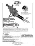
1
PLAS0H
PLAS Hand-over-Hand Rotary™ Cutters
Models: PLASOH, PLASOHPE,
PLASOH12, PLASOH12PE
OPERATOR’S MANUAL
Cortatubos rotatorios PLAS
intercambiar manos sucesivamente
Modelos: PLASOH, PLASOHPE,
PLASOH12, PLASOH12PE
MANUAL DEL OPERADOR
REED MANUFACTURING COMPANY
1425 West Eighth St. Erie, PA 16502 USA Phone | Teléfono: 814-452-3691 Fax: 814-455-1697
Toll-Free | Línea gratuita: 800-666-3691 (US/Canada/Puerto Rico)
www.reedmfgco.com
1112 – 541251
PLAS0H Models
PLAS0H
PLAS0HPE
Figure 1
Figure 2
CAPACITY
• The PLAS0H can cut and bevel plastic pipe up to 12” (335 mm) diameter.
• Take care to check specific model numbers for PVC or PE pipe.
• Blades for PE and PVC can be switched so that one cutter can work for either type of pipe.
IMPORTANT NOTE
The cutter is equipped with a carbide cut-off tool. For this reason, cutter must be rotated only in the direction indicated by the arrow. The arrow is marked on the cutter
frame. (Figure 3). If cutter is turned backward, carbide tip may be broken.
Figure 4
NOMINAL PIPE SIZE 4” (100 mm)
Short/Inner holes
6” (160 mm)
Short/Outer holes
8” (240 mm)
Long/one inner hole, one outer hole
Arrow on frame
Figure 3
2
PLAS0H MODELS
PIVOT LINK/ HOLES
OPERATING INSTRUCTIONS
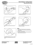
1. The pipe to be cut should be solidly supported and secured. For pipe up to 6”, the Reed R450+ Tripod (#02306) or R470+ Tripod (#09402) is recommended. For pipes larger than 6”, (150 mm) use Reed’s FPV20 Field Pipe Vise (#06027).
2. Retract the cutting and beveling tools as far as they will go into the cutter.
3. Set up the cutter for the diameter of pipe being cut by changing connecting link holes. Figure 4 lists the proper cutting link hole combinations for common
nominal pipe sizes.
4. If a cut is to be made near the end of an exposed pipe, the assembled cutter can simply be slipped over the end of the pipe. 5.
For cuts away from the end of the pipe, or in an excavated area where only a portion of the pipe is exposed, disengage one section of the cutter by removing an adjusting nut and pulling the main screw out of one of the pivot links. Place the cutter around the pipe and reassemble the cutter by engaging the main screw through the connecting link and reattaching the adjusting nut.
6. Rotate cutter so that the blade section of the cutter is on top of the pipe.
Ensure that all four rollers in the blade section are in contact with the pipe.
7. With the cut-off tool lined up with the desired cut location, tighten nuts equally until cutter is snug, yet will still rotate.
8. Rotate cutter once around pipe to ensure that the cutter remains tight. If at any point during this rotation the cutter becomes loose, tighten the adjusting nuts. The adjusting nuts are spring loaded to allow for greater out-of-round conditions.
9.
Alignment Test: Ensure the cutter is aligned properly for a straight cut. Adjust the cut-off tool so it is just touching the pipe. Rotate the cutter one complete
revolution, lightly scoring the pipe. After the full rotation, the cut-off tool should return to its original location, indicating that the cutter is aligned properly. If the cut-off tool does not return to its original location, adjust the cutter and repeat the alignment test.
10. Rotate cut-off tool knob until blade makes contact with the pipe. Rotate the cutter in the direction of the arrow by pulling cutter around the pipe until the cutter has made one revolution. 11. Feed the cut-off tool into the pipe, tightening the cut-off tool knob 1/2 turn per revolution of cutter. Excessive turning of cut-off tool knob may damage
cut-off tool.
12.
Plastic Pipe: Once the cut-off tool is halfway through the pipe, you can begin to bevel. To bevel plastic pipe, rotate the bevel tool knob until the tool touches the pipe. Rotate cutter one revolution to be sure bevel tool does not hit any high spots on the pipe.
3
13. The bevel tool knob should be rotated only 1/4 turn per one revolution of the cutter. The #4 14 Bevel Tool will produce a 15° bevel up to 5/8” long on both sides of the cut.
14.
Once the desired bevel is complete, continue feeding cut-off tool until pipe
is completely cut off. NOTE: Cutting and beveling plastic pipe can be done simultaneously as long as the cut-off tool does not cut off the pipe before the bevel is complete.
TO CHANGE CUT-OFF AND BEVEL TOOLS
Both cut-off and bevel tools can be replaced in the same manner: Rotate feed knob
clockwise until tool comes out of cutter. Reverse the procedure to replace the tool. Ensure that the tools face the proper direction, cutting in the same direction as the
arrows on the cast frame.
Dull cut-off tools, if not chipped or broken, can be sharpened by any machine shop
that has silicon carbide or diamond wheels. Ordinary grinding wheels will not effectively grind carbide. The bevel tool, made of hardened tool steel, can be sharpened
with conventional grinding equipment.
LUBRICATION
No lubrication is needed and the cutter parts should not be oiled. Dry graphite occasionally applied to the moving parts will assure long life and easy operation.
SAFETY PROCEDURES
• OPERATE TOOL UNDER OSHA AND OTHER APPLICABLE SAFETY STANDARDS.
Figure 5
Catalog No.
Item Code
Nº de catálogo Código de artículo
4
Pipe CapacityWeight
Capacidad de tubo Peso
Inches - Nominal
Actual Ø mm lbs kg
Pulgadas - nominales
Ø mm reales
libras kg
PLAS0H
04463
4 - 8 minimum 4.2” actual O.D.
4 - 8 mínimo: 4.5” de diámetro exterior real.
PLAS0HPE
04464
4 - 8 minimum 4.2” actual O.D.
4 - 8 mínimo: 4.5” de diámetro exterior real.
PLASOH12PE
04468
4 - 12 PLAS0H12
04469
4 - 12 Sections Used
Secciones utilizadas
106 - 240 21 9.6
E (2)
106 - 240 21 9.6
E (2)
106 - 335 52 23.6 E (2), B (1)
106 - 335 52 23.6 E (2), B (1)
Modelos PLAS0H
PLAS0H
PLAS0HPE
Figura 1
Figura 2
CAPACIDAD
• El PLAS0H pueden cortar y biselar tubos de plástico de hasta 12 pulg. (335 mm) de
diámetro.
•
•
enga cuidado al verificar números de modelos específicos para tubos de
T
PVC o PE.
Las hojas para PE y PVC se pueden cambiar de modo que un cortatubos pueda
funcionar para ambos tipos de tubo.
NOTAS IMPORTANTES
El cortatubos está equipado con herramienta de corte con punta de carburo. Por esta razón, sólo se debe girar el cortatubos en la dirección indicada por la flecha
(Figura 3) . Si se gira en dirección contraria, se podría romper la punta de carburo.
INSTRUCCIONES DE OPERACIÓN:
1. E
l tubo que se va a cortar se debe sostener y sujetar firmemente. Para tubos
de hasta 6 pulg. de diámetro se recomienda usar el trípode Reed R450+ (#02306)
o el trípode R470+ (#09402). Para tubos de diámetro mayor de 6 pulg. (150mm),
se recomienda usar la prensa de campo para tubos de Reed FPV20. (#06027).
2. R
etraiga las herramientas de corte y biselado lo máximo que pueda dentro
del cortatubos.
3. P
repare el cortatubos para el diámetro del tubo que se esté cortando cambiando
los agujeros de los eslabones de conexión. La Figura 4 enumera las combinaciones
correctas de agujeros para diámetros nominales usuales de tubos.
4. S
i se tiene que hacer un corte cerca del extremo de un tubo expuesto, basta
con deslizar el cortatubos armado sobre el extremo del tubo.
La flecha
Figura 3
5
Figura 4
TAMAÑO NOMINAL DE TUBOS
MODELOS PLAS0H
ESLABÓN DE
PIVOTE/AGUJEROS
4” (100 mm)
Eslabón corto y agujeros interiores
6” (160 mm)
Eslabón corto y agujeros exteriores
8” (240 mm)
Eslabón largo y un agujero interior, uno exterior
Figura 5
Catalog No.
Item Code
Nº de catálogo Código de artículo
Pipe CapacityWeight
Capacidad de tubo Peso
Inches - Nominal
Actual Ø mm lbs kg
Pulgadas - nominales
Ø mm reales
libras kg
PLAS0H
04463
4 - 8 minimum 4.2” actual O.D.
4 - 8 mínimo: 4.5” de diámetro exterior real.
PLAS0HPE
04464
4 - 8 minimum 4.2” actual O.D.
4 - 8 mínimo: 4.5” de diámetro exterior real.
PLASOH12PE
04468
4 - 12 PLAS0H12
04469
4 - 12 Sections Used
Secciones utilizadas
106 - 240 21 9.6
E (2)
106 - 240 21 9.6
E (2)
106 - 335 52 23.6 E (2), B (1)
106 - 335 52 23.6 E (2), B (1)
5. P
ara cortes alejados del extremo del tubo o en un área excavada donde solo una
parte del tubo queda expuesta, desconecte una sección del cortatubos quitando
una tuerca de ajuste y sacando el tornillo principal de uno de los eslabones de pivote.
Coloque el cortatubos alrededor del tubo y vuelva a armarlo pasando el tornillo
principal a través del eslabón de conexión y volviendo a colocar la tuerca de ajuste.
6. G
ire el cortatubos de manera que la sección de la hoja del mismo quede en la
parte superior del tubo. Compruebe que los cuatro rodillos en la sección de la
hoja hagan contacto con el tubo.
7. C
on la herramienta de corte alineada con el punto de corte deseado, apriete las
tuercas por igual hasta que el cortatubos quede ligeramente apretado, pero que
aún pueda girar.
8. D
é una vuelta al mismo alrededor del tubo para asegurar que permanece apretado. Si en cualquier punto de la rotación se afloja el cortatubos, apriete en ese
punto las tuercas de ajuste. Las tuercas de ajuste son cargadas a resorte para
permitir mayores variaciones de falta de redondez.
6
9. P
rueba de alineación: Compruebe que el cortatubos esté alineado correctamente para un corte recto. Ajuste la herramienta de corte de modo que apenas
toque el tubo. Haga girar el cortatubos una vuelta completa, rayando ligeramente el tubo. Después de esta rotación, la herramienta de corte debe volver
a su posición original, indicando que el cortatubos está correctamente alineado.
Si la herramienta de corte no vuelve a su posición original, ajuste el cortatubos
y repita la prueba de alineación.
10. Gire la perilla de la herramienta de corte hasta que la hoja entre en contacto con el
tubo. Haga girar el cortador en la dirección de la flecha tirando del cortador alrededor del tubo para completar una vuelta.
11. Avance la herramienta de corte dentro del tubo, apretando la perilla 1/2 giro por
vuelta del cortatubos. El giro excesivo de la perilla puede dañar la herramienta
de corte.
12. Cuando la herramienta de corte se encuentre a mitad del corte a través del
tubo, puede empezar a biselar. Para biselar tubos de plástico, gire la perilla de la
herramienta de biselado hasta que la herramienta entre en contacto con el tubo.
Gire el cortatubos una vuelta para verificar que la herramienta de biselado no
choque con ninguna protuberancia en el tubo.
13. Sólo se debe girar la perilla de la herramienta de biselado 1/4 de vuelta por cada
vuelta del cortatubos. La herramienta de biselado #4-14 producirá un biselado
de 15° hasta 5/8 pulg. (16 mm) de largo en ambos lados del corte.
14. Una vez terminado el biselado, continúe avanzando la herramienta de corte
hasta terminar de cortar el tubo por completo. NOTA: El corte y el biselado del
tubo plástico pueden hacerse simultáneamente siempre y cuando la herramienta de corte no termine de cortar el tubo antes de completar el biselado.
PARA CAMBIAR LAS HERRAMIENTAS DE CORTE Y BISELADO
Las herramientas de corte y biselado se pueden reemplazar de la misma manera:
Gire la perilla de avance en sentido horario hasta que la herramienta salga del
cortatubos. Invierta el procedimiento para volver a colocar la herramienta. Verifique
que las herramientas tengan la dirección correcta, cortando en la misma dirección
indicada por las flechas marcadas en el bastidor moldeado.
Las herramientas de corte sin filo, que no estén despostilladas ni rotas, se pueden
afilar en cualquier taller que tenga ruedas de diamante o de carburo de silicona.
Las ruedas abrasivas comunes no afilarán el carburo con efectividad. La herramienta
de biselado fabricada de acero endurecido para herramientas se puede afilar con
equipo de rectificación convencional.
LUBRICACIÓN
No es necesario lubricar y no se deberán aceitar las piezas del cortatubos.
La aplicación ocasional de grafito seco a las piezas móviles garantizará la larga
duración y la facilidad de funcionamiento.
PROCEDIMIENTOS DE SEGURIDAD
• EL FUNCIONAMIENTO DE LA HERRAMIENTA DEBE CUMPLIR CON LAS
NORMAS OSHA Y OTRAS NORMAS DE SEGURIDAD APLICABLES.
7
Reed Lifetime Warranty
Reed Hand Tools are for the professional trade and are warranted against all failure due to defects
in workmanship and materials for the normal life of the tool.
FAILURES DUE TO MISUSE, ABUSE, OR NORMAL WEAR AND TEAR ARE NOT COVERED
BY THIS WARRANTY.
Power units for Universal Pipe Cutters, Saw It®, Rapid Cut & Bevel™ machines, electric test
pumps, and threading power drives are warranted for a period of one year from date of purchase. Hydraulic pumps for PE Squeeze-Off tools have a one year warranty from date of purchase.
NO PARTY IS AUTHORIZED TO EXTEND ANY OTHER WARRANTY. NO WARRANTY FOR
MERCHANTABILITY OR FITNESS FOR A PARTICULAR PURPOSE SHALL APPLY.
No warranty claims will be allowed unless the product in question is received freight prepaid
at the Reed factory. All warranty claims are limited to repair or replacement, at the option of the
company, at no charge to the customer. Reed is not liable for any damage of any sort, including incidental and consequential damages. Some states do not allow
the exclusion or limitation of incidental or consequential damages, so the above exclusion may
not apply.
This warranty gives you specific legal rights, and you may also have other rights which vary
from state to state.
Garantía de por vida de Reed
Las herramientas manuales de Reed son de uso profesional y están garantizadas contra
cualquier falla debido a defectos en la mano de obra y materiales durante la vida útil normal de
dichas herramientas.
LAS FALLAS DEBIDO AL USO INCORRECTO, ABUSO, O USO Y DESGASTE NORMALES
NO ESTÁN CUBIERTAS POR ESTA GARANTÍA.
Las unidades de alimentación para los cortatubos universales, Saw It®, las maquinas de
corte y biselado (Rapid Cut & Bevel™), las bombas eléctricas de prueba y los motopropulsores
están garantizadas durante un período de un año a partir de la fecha de compra. Bombas
hidráulicas para las prensas de cierre a compresión para tubos de polietileno tienen una
garantía de un año desde la fecha de compra.
NADIE ESTÁ AUTORIZADO PARA OTORGAR NINGUNA OTRA GARANTÍA. NO SE
APLICARÁ NINGUNA GARANTÍA DE COMERCIABILIDAD O IDONEIDAD PARA UN FIN
PARTICULAR.
No se permitirá ningún reclamo de garantía excepto que el producto en cuestión se reciba
con fletes prepagados en la fábrica de Reed. Todos los reclamos de garantía están limitados
a reparación o sustitución, a elección de la compañía, y sin cargo para el cliente. Reed no es
responsable de daños de ningún tipo, incluidos los circunstanciales e indirectos. En algunos
estados no se permite la exclusión o la limitación de los daños circunstanciales o indirectos,
por lo que la exclusión anterior puede no aplicarse.
Esta garantía le otorga derechos legales específicos y usted puede contar también con
otros derechos que varían de un estado a otro.
REED MANUFACTURING COMPANY
1425 West Eighth St. Erie, PA 16502 USA
Phone | Teléfono: 814-452-3691 Fax: 814-455-1697
Toll-Free | Línea gratuita: 800-666-3691 (US/Canada/Puerto Rico)
www.reedmfgco.com
8
1112 – 54125