1
Installation
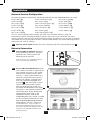
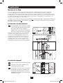
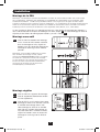
Connecting the PDU
2-1 Connect the input plug to your facility’s
compatible AC power source.
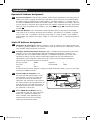
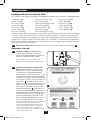
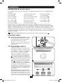
2-2 All models contain 2 banks of output
receptacles.
• PDUMVR20NET and PDUMVR30NET
contain 2 banks of 12 5-15/20R
receptacles (24 total).
Some Models Will Vary.
• PDUMVR30HVNET contains 2 banks
of 10 C13 and 2 C19 receptacles
(24 total).
Connect your equipment’s input plugs
to the appropriate outlets on the PDU.
On the Switched models, the LED near
each outlet illuminates when the outlet
is ready to distribute live AC power.
PDUMVR30HVNET Shown
Note: It is recommended that you do not
connect a live load to the PDU. If the load
you intend to connect has an ON/OFF
switch, please turn the switch to OFF prior to
connection.
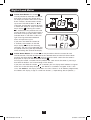
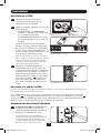
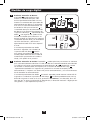
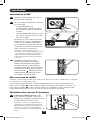
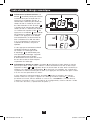
2-3 (Optional) If you attached the cord
retention bracket(s), tie each equipment
power cord to the retention bracket.
Attach each cord to the retention shelf
by looping the cord and securing it with
one of the included cable ties A . Make
sure each cord can be unplugged from
the PDU without removing the cable tie.
A
PDUMVR30HVNET Shown
Networking the PDU
Note: The MAC address of the PDU (a 12-digit string in this format: 000667xxxxxx) is printed on a label
attached to the PDU enclosure.
If your network’s DHCP server will assign a dynamic IP address to the PDU automatically, go
to Step 3-1 . If you will assign a static IP address to the PDU manually, go to Step 4-1 . If you
are uncertain which method to use, contact your network administrator for assistance before
continuing the installation process.
Dynamic IP Address Assignment
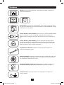
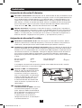
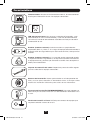
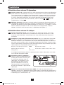
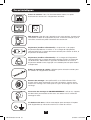
3-1 Connect PDU to Network: While the
PDU is powered, connect a standard
Ethernet patch cable to the RJ-45
Ethernet port on the PDU.
Note: This port is not compatible with PoE
(Power over Ethernet) applications. The PDU
will attempt to obtain an IP address via DHCP.
This may take as long as several minutes,
depending on your network environment.
4
201207109-93-3161.indb 4
8/14/2012 2:03:46 PM