Download PROPANE CONSTRUCTION HEATER
Transcript
PROPANE CONSTRUCTION HEATER OWNER’S MANUAL For more information, visit www.desatech.com Variable 30,000, 40,000, 50,000 Btu/Hr IMPORTANT: Read and understand this manual before assembling, starting or servicing heater. Improper use of heater can cause serious injury. Keep this manual for future reference. GENERAL HAZARD WARNING: FAILURE TO COMPLY WITH THE PRECAUTIONS AND INSTRUCTIONS PROVIDED WITH THIS HEATER, CAN RESULT IN DEATH, SERIOUS BODILY INJURY AND PROPERTY LOSS OR DAMAGE FROM HAZARDS OF FIRE, EXPLOSION, BURN, ASPHYXIATION, CARBON MONOXIDE POISONING, AND/OR ELECTRICAL SHOCK. ONLY PERSONS WHO CAN UNDERSTAND AND FOLLOW THE INSTRUCTIONS SHOULD USE OR SERVICE THIS HEATER. IF YOU NEED ASSISTANCE OR HEATER INFORMATION SUCH AS AN INSTRUCTIONS MANUAL, LABELS, ETC. CONTACT THE MANUFACTURER. TABLE OF CONTENTS SAFETY INFORMATION ............................................................ 2 MAINTENANCE .......................................................................... 6 PRODUCT IDENTIFICATION ..................................................... 3 TROUBLESHOOTING ................................................................ 7 UNPACKING ............................................................................... 3 SERVICE PROCEDURES .......................................................... 8 PROPANE SUPPLY .................................................................... 3 ILLUSTRATED PARTS BREAKDOWN AND PARTS LIST ....... 10 THEORY OF OPERATION ......................................................... 4 SPECIFICATIONS .................................................................... 12 ASSEMBLY ................................................................................. 4 ACCESSORIES ........................................................................ 12 INSTALLATION ........................................................................... 4 REPLACEMENT PARTS .......................................................... 12 VENTILATION ............................................................................. 5 OWNER’S REGISTRATION FORM .......................................... 13 OPERATION ............................................................................... 5 WARRANTY AND REPAIR SERVICE ........................ Back Cover STORAGE ................................................................................... 6 Save this manual for future reference. 2 SAFETY INFORMATION SAFETY INFORMATION WARNINGS WARNING: This product contains and/or generates chemicals known to the State of California to cause cancer or birth defects, or other reproductive harm. WARNING: FIRE, BURN, INHALATION, AND EXPLOSION HAZARD. KEEP SOLID COMBUSTIBLES, SUCH AS BUILDING MATERIALS, PAPER OR CARDBOARD, A SAFE DISTANCE AWAY FROM THE HEATER AS RECOMMENDED BY THE INSTRUCTIONS. NEVER USE THE HEATER IN SPACES WHICH DO OR MAY CONTAIN VOLATILE OR AIRBORNE COMBUSTIBLES, OR PRODUCTS SUCH AS GASOLINE, SOLVENTS, PAINT THINNER, DUST PARTICLES OR UNKNOWN CHEMICALS. WARNING: NOT FOR HOME OR RECREATIONAL VEHICLE USE. The heater is designed for use as a construction heater in accordance with ANSI Z83.7/CGA 2.14. Other standards govern the use of fuel gases and heating products for specific uses. Your local authority can advise you about these. The primary purpose of construction heaters is to provide temporary heating of buildings under construction, alteration or repair. Properly used, the heater provides safe economical heating. Products of combustion are vented into the area being heated. We cannot foresee every use which may be made of our heaters. CHECK WITH YOUR LOCAL FIRE SAFETY AUTHORITY IF YOU HAVE QUESTIONS ABOUT HEATER USE. Other standards govern the use of fuel gases and heat producing products for specific uses. Your local authorities can advise you about these. Carbon Monoxide Poisoning: Some people are more affected by carbon monoxide than others. Early signs of carbon monoxide poisoning resemble the flu, with headaches, dizziness, and/or nausea. If you have these signs, the heater may not be working properly. Get fresh air at once! Check for proper ventilation and have heater serviced. Propane Gas: Propane gas is odorless. An odor-making agent is added to propane gas. The odor helps you detect a propane gas leak. However, the odor added to propane gas may fade. Propane gas may be present even though no odor exists. Make certain you read and understand all warnings. Keep this manual for reference. It is your guide to safe and proper operation of this heater. • Install and use heater with care. Follow all local ordinances and codes. In the absence of local ordinances and codes, refer to the Standard for Storage and Handling of Liquefied Petroleum Gas, ANSI/NFPA 58 and the Natural Gas Installation Code, CAN/CGA B149.2. This instructs on the safe storage and handling of propane gases. • Use only the electrical voltage and frequency specified on model plate. • The electrical connections and grounding of the heater shall follow the National Electric Code, ANSI/NFPA 70, or Canadian Electrical Code, part 1. • Electrical grounding instructions — This appliance is equipped with a three-prong (grounding) plug for your protection against shock hazard and should be plugged directly into a properly grounded three-prong receptacle. • Use only a three-prong, grounded extension cord. • Use only the hose and factory preset regulator provided with the heater. • Use only propane gas set up for vapor withdrawal. • Provide adequate ventilation. Before using heater, provide at least a 1.5-square-foot (13,9 decímetros) opening of fresh, outside air. • This product has been approved for use in the Commonwealth of Massachusetts. • For indoor use only. Do not use heater outdoors. • Do not use heater in occupied dwellings or in living or sleeping quarters. • Do not use heater below ground level. Propane gas is heavier than air. If a leak occurs, propane gas may sink to the lowest possible level. • Keep appliance area clear and free from combustible materials, gasoline, paint thinner, and other flammable vapors and liquids. Do not use heater in areas with high dust content. • Minimum heater clearances from combustibles: Outlet: 6 Ft. (1,83 m) Sides: 2 Ft. (60,96 cm) Top: 6 Ft. (1,83 m) Rear: 2 Ft. (60,96 cm) • Keep heater at least six feet from propane tank(s). Do not point heater at propane tank(s) within 20 feet (6 m). • Keep propane tank(s) below 100° F (37,8° C). • Check heater for damage before each use. Do not use a damaged heater. • Check hose before each use of heater. If highly worn or cut, replace before using heater. • Locate heater on stable and level surface if heater is hot or operating. • Not intended for use on finished floors. • Never block air inlet (rear) or air outlet (front) of heater. • Keep heater away from strong drafts, water spray, rain, or dripping water. • Do not leave heater unattended. • Keep children and animals away from heater. • Never move, handle, or service a hot, operating, or plugged-in heater. Severe burns may result. Wait 20 minutes after turning heater off. For more information, visit www.desatech.com 111708-01A SAFETY INFORMATION PRODUCT IDENTIFICATION UNPACKING PROPANE SUPPLY SAFETY INFORMATION UNPACKING Continued 1. • • • • • • To prevent injury, wear gloves when handling heater. Never attach duct work to heater. Do not alter heater. Keep heater in its original state. Do not use heater if altered. Turn off propane supply and unplug heater when not in use. Use only original replacement parts. This heater must use design-specific parts. Do not substitute or use generic parts. Improper replacement parts could cause serious or fatal injuries. PRODUCT IDENTIFICATION Hot Air Outlet (Front) Handle Motor Fan Heater Base Power Cord Valve Inlet Remove all packing items applied to heater for shipment. Keep plastic cover caps (attached to inlet connector and hose/regulator assembly) for storage. Remove all items from carton. Check all items for shipping damage. If heater is damaged, promptly inform dealer where you bought heater. PROPANE SUPPLY Propane gas and propane tank(s) are to be furnished by the user. Use this heater only with a propane vapor withdrawal supply system. See Chapter 5 of the Standard for Storage and Handling of Liquefied Petroleum Gas, ANSI/NFPA 58 and/or CAN/CGA B149.2. Your local library or fire department will have this booklet. The amount of propane gas ready for use from propane tanks varies. Two factors decide this amount: 1. The amount of propane gas in tank(s) 2. The temperature of tank(s) Shell Piezo Ignitor Button Automatic Control Valve Knob 2. 3. This heater is designed to operate with a minimum 20-pound (9 kg) propane tank. You may need two or more tanks or one larger tank in colder weather. Use a 100-pound (45 kg) tank for longer operation or in very cold weather. Less gas is vaporized at lower temperatures. Your local propane gas dealer will help you select the proper supply system. The minimum surrounding air temperature rating for each heater is -20°F (-29°C). Average Temperature (°F/C°) At Tank Location 40° (4,44°) 32° (0°) 20° (-6,67°) 10° (-12,22°) 0° (-17,78°) -10° (-23,33°) -20° (-28,89°) Hose / Regulator Assembly Figure 1 - 50,000 BTU/Hr Model For more information, visit www.desatech.com 111708-01A 3 3 Number Of Tanks (100-pound [45 kg]) 1 1 1 1 1 2 2 4 THEORY OF OPERATION ASSEMBLY INSTALLATION THEORY OF OPERATION The Fuel System: The hose/regulator assembly attaches to the Flat Side Facing Up propane gas supply. This provides fuel to the heater. Nut Clip The Air System: The motor turns the fan. The fan pushes air into and Shell around the combustion chamber. This air is heated and provides a stream of clean, hot air. Slot The Ignition System: The piezo ignitor lights the burner. The Automatic Control System: This system causes the heater to shut down if the flame goes out. Combustion Chamber Fan Motor Figure 4 - Installing Nut Clip Clean Heated Air Out (Front) Screws Cool Air In (Back) Handle Hose/ Regulator Assembly Air For Combustion Nut Clip Rear of Heater Air For Heating Figure 2 - Cross Section Operational View ASSEMBLY 1. 2. 3. Remove screw from top of fan guard (see Figure 3). Discard screw. Insert nut clip (provided with handle) with flat side facing up through slot in top of shell. Align holes in nut clip with screw hole behind slot in top of shell. (see Figure 4). Place handle over hole and clip. Insert two screws (provided with handle) through handle and tighten into shell. Make sure rear screw goes through shell and into fan guard. Tighten screws firmly. Figure 5 - Attaching Handle INSTALLATION WARNING: Review and understand the warnings in the Safety Information section, pages 2 and 3. They are needed to safely operate this heater. Follow all local codes when using this heater. Screw WARNING: Test all gas piping and connections for leaks after installation or servicing. Never use an open flame to check for a leak. Apply a mixture of liquid soap and water to all joints. Bubbles forming show a leak. Correct all leaks at once. Figure 3 - Removing Screw from Top of Fan Guard 1. 2. Provide propane supply system (see Propane Supply, page 3). Connect fuel gas fitting on hose/regulator assembly to propane tank(s). Turn fuel gas fitting counterclockwise into threads on tank. Tighten firmly using a wrench. IMPORTANT: Position regulator so that hose leaving the regulator is in a horizontal position (see Figure 6, page 5). This places the regulator vent in the proper position to protect it from the weather. For more information, visit www.desatech.com 111708-01A INSTALLATION VENTILATION OPERATION INSTALLATION 5 5 VENTILATION Continued 3. 4. 5. 6. Connect hose to valve inlet. Tighten firmly using a wrench. You must use the regulator supplied with heater. Open propane supply valve on propane tank(s) slowly. Note: If not opened slowly, excess-flow check valve on propane tank may stop gas flow. If this happens, close propane supply valve and open again slowly. Check all connections for leaks. Apply mixture of liquid soap and water to gas joints. Bubbles forming show a leak that must be corrected. Close propane supply valve. WARNING: Never use an open flame to check for a leak. Apply a mixture of liquid soap and water to all joints. Bubbles forming show a leak that must be corrected. Correct all leaks at once. Regulator Propane Supply Valve Hose Propane Tank WARNING: Provide at least a 1.5 square foot (1,400 cm2) opening of fresh, outside air while running heater. If proper fresh, outside air ventilation is not provided, carbon monoxide poisoning can occur. Provide proper fresh, outside air ventilation before running heater. OPERATION WARNING: Review and understand the warnings in the Safety Information section, pages 2 and 3. They are needed to safely operate this heater. Follow all local codes when using this heater. TO START HEATER 1. 2. 3. Fuel Gas Fitting Figure 6 - Regulator Position 4. 5. Knob Follow all installation, ventilation, and safety information. Locate heater on stable and level surface. Make sure strong drafts do not blow into front or rear of heater. Plug power cord of heater into a three-prong, grounded extension cord. Extension cord must be at least six feet (1,83 m) long. Extension cord must be UL listed. Extension Cord Wire Size Requirements Up to 50 feet (15,24 m) long, use 18 AWG rated cord. 51 to 100 feet (15,54 hasta 30,48 m) long, use 16 AWG rated cord. 101 to 200 feet (30,78 hasta 60,96 m) long, use 14 AWG rated cord. Plug extension cord into a 120 volt/60 hertz, 3-hole, grounded outlet. Motor will start. Fan will turn, forcing air out front of heater. Open propane supply valve on propane tank(s) slowly. Note: If not opened slowly, excess-flow check valve on propane tank may stop gas flow. If this happens, close propane supply valve and open again slowly. WARNING: Be sure motor and fan are running before pushing in automatic control valve button. Flames could flash outside heater if motor and fan are not running. 6. Valve Inlet Hose Figure 7 - Hose and Inlet Connector Turn control knob to the low position and push in (see Figure 8 and 9, page 6). Hold knob in and push piezo ignitor button. You may need to push piezo ignitor button 3-8 times until the main burner lights. When main burner lights, keep automatic control valve knob pushed in. Release button after 30 seconds. Note: If main burner fails to light, hose may have air in it. If so, keep control knob pressed and wait 20 seconds. Release control knob and wait 20 seconds for unburned fuel to exit heater. Repeat step 6. For more information, visit www.desatech.com 111708-01A 6 OPERATION STORAGE MAINTENANCE OPERATION STORAGE Continued 7. 8. If main burner goes out, repeat step 6, page 5. When main burner remains lit, rotate control knob to the desired heat level. CAUTION: Disconnect heater from propane supply tank(s). 1. OFF START/ LOW 2. 3. MED HIGH 4. Figure 8 - Control Knob Positions Store propane tank(s) in safe manner. See Chapter 5 of Standard for Storage and Handling of Liquefied Petroleum Gases, ANSI/NFPA 58. Follow all local codes. Always store propane tanks outdoors. Place plastic cover caps over brass fittings on inlet connector and hose/regulator assembly. Store in dry, clean, and safe place. Do not store hose/regulator assembly inside heater combustion chamber. When taking heater out of storage, always check inside of heater. Insects and small animals may place foreign objects in heater. Remove motor and other internal parts if needed to remove foreign objects (see Service Procedures, page 8). MAINTENANCE WARNINGS • Never service heater while it is plugged in, connected to propane supply, operating, or hot. Severe burns and electrical shock can occur. • Keep heater clear and free from combustible materials, gasoline, and other flammable vapors and liquids. • Do not block the flow of combustion or ventilation air. Piezo Ignitor Button Automatic Control Valve Knob Figure 9 - Automatic Control Valve Button and Piezo Ignitor Button 1. TO STOP HEATER 1. 2. Tightly close propane supply valve on propane tank(s). Allow heater to burn remaining fuel in hose. Shut off main burner valve. Do this by turning control knob to the OFF position until it stops. TO RESTART HEATER 1. 2. Wait five minutes after stopping heater. Repeat steps under To Start Heater, page 5. 2. 3. 4. 5. 6. Keep heater clean. Clean heater annually or as needed to remove dust and debris. If heater is dirty or dusty, clean heater with a damp cloth. Use household cleaners on difficult spots. Inspect heater before each use. Check connections for leaks. Apply mixture of liquid soap and water to connections. Bubbles forming show a leak. Correct all leaks at once. Inspect hose/regulator assembly before each use. If hose is highly worn or cut, replace. Have heater inspected yearly by a qualified service agency. Keep inside of heater free from combustible and foreign objects. Remove motor and other internal parts if needed to clean inside of heater (see Service Procedures, page 8). Clean fan blades each season or as needed (see Fan, page 8). For more information, visit www.desatech.com 111708-01A TROUBLESHOOTING 7 7 TROUBLESHOOTING Note: For additional help, visit DESA Heating Products’ Technical Service web site at www.desatech.com. WARNING: Never service heater while it is plugged in, connected to propane supply, operating, or hot. Severe burns and electrical shock can occur. OBSERVED FAULT POSSIBLE CAUSE REMEDY Fan does not turn when heater is plugged in. 1. No electrical power to heater 1. Check voltage to electrical outlet. If voltage is good, check heater power cord for breaks 2. Adjust motor/fan guard to keep fan from hitting inside of heater shell. Bend fan guard if necessary 3. Replace fan. See Fan, page 8 4. Replace motor. See Motor, page 8 2. Fan hitting inside of heater shell 3. Fan blades bent 4. Defective motor Heater will not ignite. 1. User did not follow installation or operation instructions properly 2. No spark at ignitor. To test for spark, follow step 9 under Ignitor, page 9. If you see spark at ignitor, have heater serviced by qualified service person. If no spark seen: A) Loose or disconnected ignitor wire B) Wrong spark gap C) Piezo ignitor loose D) Bad ignitor electrode Heater shuts down while running. 1. High surrounding air temperature causing thermal limit device to shut down heater 2. Restricted air flow 3. Damaged fan 4. Excessive dust or debris in surrounding area 1. Repeat installation and operation instructions. See Installation, page 5 and Operation, pages 5 and 6 2. A) Check ignitor wire. Tighten or reattach loose ignitor wire. See Figure 14, page 9 for ignitor wire location B) Set gap between ignitor electrode and target plate to .17" (4,3 mm) C) Tighten nut holding piezo ignitor to base of heater D) Replace ignitor electrode. See Ignitor, page 9 1. This can happen when running heater in temperatures above 85°F (29,44° C). Run heater in cooler temperatures 2. Check heater inlet and outlet. Remove any obstructions 3. Replace fan. See Fan, page 8 4. Clean heater. See Maintenance, page 6 WARNING: Use only in areas free of high dust content. For more information, visit www.desatech.com 111708-01A 8 SERVICE PROCEDURES SERVICE PROCEDURES WARNING: Never service heater while it is plugged in, connected to propane supply, operating, or hot. Severe burns and electrical shock can occur. Setscrew ELECTRICAL SYSTEM The entire electrical system for this heater is contained within the motor. If any part of the electrical system is damaged, you must replace motor. MOTOR 1. 2. 3. Remove three screws that attach fan guard to heater shell. Remove motor and fan guard from heater shell (see Figure 10). Use hex wrench to loosen set screw which holds fan to motor shaft (see Figure 11). Remove fan. Be careful not to damage the fan blade pitch. 4. Remove two nuts and two screws that attach fan guard to motor using nut-driver. Remove fan guard from motor (see Figure 12). 5 Disconnect the green power cord wire from motor and remove black and white wire terminals. 6. Discard old motor. 7. Attach green power cord wire to motor. 8. Attach fan guard to new motor with two nuts and two screws. 9. Replace black and white terminals. 10. Place fan onto motor shaft of new motor. Make sure set screw contacts flat surface on motor shaft. Tighten set screw firmly (40-50 inch-pounds [46,08 a 57,60 kgf/cm]). 11. Place motor and fan guard into rear of heater shell. Make sure power cord is properly located (see Figure 13). 12. Insert three screws through heater shell and into fan guard. Tighten screws firmly. Figure 11 - Setscrew Location Figure 12 - Removing or Attaching Fan Guard from Motor Figure 13 - Replacing Motor and Fan Guard into Heater FAN 1. 2. 3. Remove three screws that attach fan guard to heater shell. Remove motor and fan guard from heater shell (see Figure 10). Use hex wrench to loosen set screw that holds fan to motor shaft (see Figure 11). 4. Remove fan. Be careful not to damage the fan blade pitch. 5a. If replacing fan, remove old fan and discard. Go to step 7 below. 5b. If cleaning fan,use soft cloth moistened with kerosene or solvent. 6. Dry fan thoroughly. 7. Place fan onto motor shaft. Make sure set screw contacts flat surface on motor shaft. Tighten set screw firmly (40-50 inch-pounds [46,08 a 57,60 kgf/cm]). 8. Place motor and fan guard into rear of heater shell. Make sure power cord is properly located (see Figure 13). 9. Insert three screws through heater shell and into fan guard. Tighten screws firmly. Figure 10 - Removing Motor and Fan Guard from Heater For more information, visit www.desatech.com 111708-01A SERVICE PROCEDURES 9 9 SERVICE PROCEDURES Continued IGNITOR 1. 2. 3. 4. 5. 6. 7. Rear Head Remove motor and fan guard from heater (see Motor, page 8, steps 1 through 5). Remove black ignitor wire from piezo ignitor. Access ignitor wire through underside of heater base (see Figure 14). Push wire up through bushing in heater shell. Remove ignitor mounting screw from rear head using nut-driver or standard screwdriver (see Figure 15). Remove ignitor from rear head. Install new ignitor. Attach ignitor to rear head with ignitor mounting screw. Run ignitor wire from new ignitor through bushing in heater shell. Attach ignitor wire to piezo ignitor. Set gap between ignitor electrode and target plate to .17" (4,3 mm). See Figure 16. Ignitor Ignitor Mounting Screw Figure 15 - Removing Ignitor Mounting Screw and Ignitor Target Plate WARNING: Make sure heater is disconnected from propane supply. Heater could ignite causing severe burns. 8. 9. Test for spark. Push piezo ignitor button and watch for spark between ignitor electrode and target plate. Place motor and fan guard into rear of heater shell (see Motor, page 8, steps 9 through 10). Gap Area Figure 16 - Clearance between Ignitor Electrode and Target Plate Piezo Ignitor Ignitor Wire Bushing Underside of Heater Base Figure 14 - Removing Ignitor Wire from Piezo Ignitor For more information, visit www.desatech.com 111708-01A Ignitor Electrode 10 ILLUSTRATED PARTS BREAKDOWN Models RLP50VA and RM50PVA ILLUSTRATED PARTS BREAKDOWN MODELS RLP50VA AND RM50PVA 1 2 7 3 10 4 11 2 18 16 20 2 19 17 9 6 20 21 22 21 24 15 23 12 27 13 25 8 26 14 5 28 For more information, visit www.desatech.com 111708-01A PARTS LIST Models RLP50VA and RM50PVA PARTS LIST MODELS RLP50VA AND RM50PVA This list contains replaceable parts used in your heater. When ordering parts, follow the instructions listed under Replacement Parts on page 12 of this manual. KEY NO. PART NO. DESCRIPTION 1 2 3 ** M11084-26 105333-02 105333-01 104786-01 M11143-1 101480-12 M11084-27 099393-03 105341-01 099539-01 M11084-38 101478-03 105332-01 103863-01 097384-02 097968-05 NPC-00C 101481-04 097776-01 099237-01 104146-01 103921-01 102445-01 078978-03 105335-01 099202-02 M12461-14 098219-25 Combustion Chamber Hex Tap Screw, #10-16 x 3/8" Outer Shell (RM50PVA) Outer Shell (RLP50VA) Handle Kit Bushing, Strain Relief Wire Assembly Hex Tap Screw, #12-14 x 1/2" Knob, Control Burner Assembly Electrode Ignitor Hex Tap Screw, #8-18 x 3/8" Fan Motor Fan Guard Captive Washer Nut Hex Screw, #4-40 x 1/2" Hex Nut, #4-40 Thermal Switch Universal Bushing Thermocouple Nut Thermocouple Valve/Orifice Assembly Piezo Ignitor Sleeve Cap Base Assembly Steel Rivet, 1/8" Hex Screw, 8-32 x 3/8 Cord, Power Supply 4 5 6 7 8 9 10 11 12 13 14 15 16 17 18 19 20 21 22 23 24 25 26 27 28 QTY. 1 7 1 1 1 1 1 3 1 1 1 1 1 1 1 3 2 2 1 1 2 1 1 1 1 1 1 2 1 PARTS AVAILABLE - NOT SHOWN 109111-02 110396-02 103867-07 103869-05 099672-04 Tradename Decal (RLP50VA) Tradename Decal (RM50PVA) General Information Decal Operation Decal Notice Decal ** Not a field replaceable part. For more information, visit www.desatech.com 111708-01A 2 2 1 1 1 11 11 12 SPECIFICATIONS ACCESSORIES REPLACEMENT PARTS TECHNICAL SERVICE SPECIFICATIONS Output Rating (BTU/Hr) High ......................................................49,500 Medium ................................................40,000 Low ......................................................30,000 Fuel ............................................................Propane Vapor Only Fuel Consumption Gallons/Hour ........................................ 2.19 / 1.09 Pounds/Hour .........................................9.28 / 4.64 Supply Pressure To Regulator Minimum (for input adjustment) .......... 10 psi Maximum ............................................. 200 psi Regulator Outlet Pressure High ......................................................18" WC Manifold Pressure High ......................................................13.7" WC Low ......................................................17" WC Hot Air Output (CFM Approx) .................275 Motor ......................................................... 3,300 RPM, 1/20 HP Electric Input ............................................. 120 volt/60 hertz Amperage ..................................................2 Ignition ......................................................Manual, Piezo Ignitor Gap .................................................0.17" Temperature Range for Operation* ...........-20°F to 85°F * Heater Weight (Pounds) ............................ 13 Shipping Weight ........................................ 15 Size - L x W x H (Inches) Heater ................................................... 18.5 x 8.0 x 12.8 Carton ................................................... 19.4 x 9.75 x 14.75 REPLACEMENT PARTS WARNING: Use only original replacement parts. This heater must use design-specific parts. Do not substitute or use generic parts. Improper replacement parts could cause serious or fatal injuries. This will also protect your warranty coverage for parts replaced under warranty. Parts Under Warranty Contact authorized dealers of this product. If they can’t supply original replacement part(s), either contact your nearest authorized service center or call DESA Heating Products’ Technical Service Department at 1-866-672-6040. When calling DESA Heating Products, have ready • your name • your address • model number of your heater • how heater was malfunctioning • purchase date In most cases, we will ask you to return the part to the factory. Parts Not Under Warranty Contact authorized dealers of this product. If they can’t supply original replacement part(s), either contact your nearest Parts Central or call DESA Heating Products at 1-866-672-6040 for referral information. * When running heater in temperatures above 85° F, high internal temperatures may cause thermal limit device to shut down heater. When calling DESA Heating Products, have ready • model number of your heater • the replacement part number ACCESSORIES TECHNICAL SERVICE Purchase accessories and parts from your nearest dealer or service center. If they can not supply an accessory or part, either contact your nearest Parts Central (listed in the separate Authorized Service Center booklet) or contact DESA Heating Products for information. You may have further questions about this heater. If so, contact DESA Heating Products’ Technical Service Department at 1-866-672-6040. When calling, please have your model and serial numbers of your heater ready. DESA Heating Products P.O. Box 90004 Bowling Green, KY 42102-9004 1-866-672-6040 You can also visit DESA Heating Products’ Technical Service web site at www.desatech.com. Part Number Description LPA3055 Hose/Regulator Assembly U.L. listed. LPA4020 Fuel Gas Connector Connects regulator to all standard propane tanks. U.L. and A.G.A. listed. For more information, visit www.desatech.com 111708-01A 13 13 OWNER'S REGISTRATION FORM Complete registration form and mail or complete on-line registration at www.desatech.com within 30 days after purchase. Brand: (Reddy Heater, Master, Remington, etc.) Model: (R60, HD15, etc.) Date Purchased: Note: Keep receipt for warranty verification. Serial Number: 7 or 9 digit number located on product or identification tag. First Name: Last Name: Address: City: State: Phone: ( ) - Zip: Country: E-Mail: Please answer the following questions to register your product with DESA Heating Products: 1. Who will heater be used by? ❍ Individual ❍ Business 2. Will you use your heater in more than one location? ❍ Yes 3. Where will the product be used? (You may select more than one.) ❍ Workshop ❍ Barn ❍ Residential Construction ❍ No ❍ Commercial Construction ❍ Garage ❍ Factory ❍ Recreation ❍ Warehouse ❍ Utility Shed/Outbuilding ❍ Other ______________________________ (Specify) 4. Cost of product (excluding sales tax)? $________________________________ 5. Maintenance/service work will be performed by: ❍ Self 6. If you bought this product yourself, did you plan to purchase this type of product before going into the store? ❍ Service Center 7. Type of store where product was purchased? ❍ Hardware ❍ Farm/Ag. Supply ❍ Discount Store ❍ Other ___________________________________ ❍ Propane Dealer ❍ Natural Gas/Utility Co. ❍ Auto Parts ❍ Warehouse Club ❍ Industrial/Contractor Supply ❍ HVAC Dealer ❍ Yes ❍ No ❍ Home Center or Builder’s Supply ❍ Rental Store ❍ Other _________________________________________________ ❍ Propane (LP Gas) ❍ Natural Gas ❍ Kerosene ❍ Diesel ❍ Electric ❍ Other________________ 8. What is your primary source of heat? 9. What motivated you to buy this product? ❍ Sudden Cold Weather ❍ Replace Older Model ❍ D.I.Y. Home Project ❍ Emergency Back-Up Heat ❍ Heater on Sale ❍ Construction Project ❍ Hard to Heat Location 10. How did you learn about this product brand? ❍ Advertisement ❍ Store Display ❍ Previously Owned a Heater ❍ Other ________________________________ ❍ Relative or Friend ❍ Co-Worker ❍ Store Representative ❍ Other _________________________________________________(Specify) 11. What other brands did you consider? ❍ None ❍ Master ❍ Remington ❍ All-Pro ❍ Dayton ❍ Universal ❍ Mr. Heater ❍ L.B. White Tradesman ❍ John Deere ❍ Dyna-Glo ❍ Dura-Heat ❍ Paulin ❍ Coleman ❍ Vogelzang American ❍ Other ___________________________________ 12. Who selected the product? ❍ Male ❍ Female ❍ Both 13. Level of Education of Purchaser: ❍ High School 14. Age of Purchaser: ❍ Under 20 ❍ 20 - 29 ❍ Vocation/Technical School ❍ 30 - 39 ❍ 40 - 49 15. Buyer’s total annual household income: ❍ Under $19,999 ❍ $50,000 to $74,999 ❍ $75,000 to $99,999 ❍ Some College ❍ Completed College ❍ Graduate School ❍ 60 or Over ❍ $20,000 to $34,999 ❍ $35,000 to $49,999 ❍ $100,000 and Over 16. What is the population of your area? ❍ Under 10,000 ❍ 100,000 to 250,000 ❍ 50 - 59 ❍ 10,000 to 25,000 ❍ 25,000 to 50,000 ❍ 50,000 to 100,000 ❍ Over 250,000 17. Store where product was purchased: Name: ______________________________________ City: _____________________________________ State: __________ 18. In choosing this product, how important were the following: Not Somewhat Very ❍ ❍ ❍ Availability ❍ ❍ ❍ Price ❍ ❍ ❍ Brand Name ❍ ❍ ❍ Overall Quality ❍ ❍ ❍ Heat Output (Btu/Hr Rating) Variable Heat Output (Btu/Hr) Made in USA Warranty Local Service Value for Price ❍ ❍ ❍ ❍ ❍ ❍ ❍ ❍ ❍ ❍ ❍ ❍ ❍ ❍ ❍ Size Prior Brand Experience Built-In Thermostat Ease of Operation Special Features Salesperson’s Recommendation Friend/Relative’s Recommendation Portability Quiet Operation Not ❍ ❍ ❍ Somewhat ❍ ❍ ❍ Very ❍ ❍ ❍ ❍ ❍ ❍ ❍ ❍ ❍ ❍ ❍ ❍ ❍ ❍ ❍ ❍ ❍ ❍ ❍ ❍ ❍ 19. This question will allow us to better understand the demographic profile of our customers. Which of the following best describes you? (not required) For more information, visit www.desatech.com ❍ 111708-01A African American ❍ Asian American ❍ Mexican ❍ Puerto Rican ❍ Cuban ❍ Other Hispanic ❍ White ❍ Other ___________________ TAPE Postage Required 2701 Industrial Drive P.O. Box 90004 Bowling Green, KY 42102-9004 TAPE W AR NIN G klsu ;e iejlb ;;pd oek l;lkl lhi suie kok jlb le ,,;lo oek g;e lhi kok ;;pd l;lkl le ,,;lo suie klsu g;e ;l klsuiejlb jlb ;;pd oe klsu iejlboek lhi l;l klsu iejlb oek kok le klsu iejlb oek lhi kok ,,;lo lhi klsu iejlb oek g;e lhi kokle le ,,;lo klsu iejlb oek kok ,,;lo g;e ;;pd l;l iejlb oek lhi kok le ,,;lo g;e ;;pd klsu oek lhi kok le ,,;lo g;e ;;pd l;l klsuiejlb lhi kok le ,,;lo g;e ;;pd l;l klsu iejlboek l;l lhi le klsu iejlb ,,;lo g;e ;;pd oek kok g;e ;;pd l;l klsu iejlb oek lhi le ,,;lo ;;pd l;l iejlb oek lhi kokkok g;e le l;l ,,;lo oek lhi kok le klsu ,,;lo g;e ;;pd lhi l iejlb kok le ,,;lo g;e ;;pd oek le ,,;lo g;e ;;pd l;l lhi g;e ;;pd l;l kok le ;;pd l;l ,,;lo l;l g;e ;;pd l;l WARNING klsuiejlb oeklhi kokle ,,;log;e ;l klsuiejlb ;;pdl;l klsuiejlb oeklhi klsuiejlb oeklhi kokle ,,;log;e oeklhi kokle ;;pdl;l ,,;log;e ;;pdl klsuiejlb oeklhikokle ,,;log;e ;;pdl;l klsuiejlb oeklhi kokle klsuiejlb oeklhikokle ,,;log;e ;;pdl;lklsuiejlb oeklhi kokle ,,;log;e ;;pdl;l klsuiejlb oeklhikokle ,,;log;e ;;pdl;lklsuiejlb oeklhi kokle,,;log;e ;;pdl;l klsuiejlb oeklhikokle ,,;log;e ;;pdl;lklsuiejlb oeklhi kokle,,;log;e ;;pdl;l ,,;log;e ;;pdl;l kokle ,,;log;e ;;pdl;l klsuiejlb oeklhi kokle ,,;log;e ;;pdl;l klsuiejlb oeklhi kokle ,,;log;e ;e ;;pdl;lklsuie jlb oeklhi ;;pdl;lklsuiejlb oeklhi kokle ,,;log;e ;;pdl;l OTHER OUTDOOR HEATING PRODUCTS PROPANE/LP FORCED AIR HEATERS PROPANE/LP CONVECTION HEATERS PORTABLE KEROSENE/DIESEL FORCED AIR HEATERS PROPANE/LP TANK TOP HEATERS PROPANE/LP AND NATURAL GAS GARAGE HEATERS PROPANE/LP PATIO HEATERS PROPANE/LP AND NATURAL GAS CHIMENEAS 
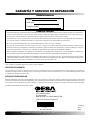
16 WARRANTY AND REPAIR SERVICE KEEP THIS WARRANTY Model Serial No. Date of Purchase LIMITED WARRANTY DESA Heating Products warrants this product and any parts thereof, to be free from defects in materials and workmanship for one (1) year from the date of first purchase when operated and maintained in accordance with instructions. This warranty is extended only to the original retail purchaser, when proof of purchase is provided. This warranty covers only the cost of parts and labor required to restore the product to proper operating condition. Transportation and incidental costs associated with warranty repairs are not reimbursable under this warranty. Warranty service is available only through authorized dealers and service centers. This warranty does not cover defects resulting from misuse, abuse, negligence, accidents, lack of proper maintenance, normal wear, alteration, modification, tampering, contaminated fuels, repair using improper parts, or repair by anyone other than an authorized dealer or service center. Routine maintenance is the responsibility of the owner. THIS EXPRESS WARRANTY IS GIVEN IN LIEU OF ANY OTHER WARRANTY EITHER EXPRESSED OR IMPLIED, INCLUDING WARRANTIES OF MERCHANTABILITY AND FITNESS FOR A PARTICULAR PURPOSE. DESA Heating Products assumes no responsibility for indirect, incidental or consequential damages. Some states do not allow the exclusion or limitation of incidental or consequential damages, or limitations or exclusions may not apply to you. This Limited Warranty gives you specific legal rights and you may also have other rights which vary from state to state. We reserve the right to amend these specifications at any time without notice. The only warranty applicable is our standard written warranty. We make no other warranty, expressed or implied. WARRANTY SERVICE Should your heater require service, return it to your nearest authorized service center. Proof of purchase must be presented with the heater. The heater will be inspected. A defect may be caused by faulty materials or workmanship. If so, DESA Heating Products will repair or replace the heater without charge. REPAIR SERVICE Return your heater to your nearest authorized service center. Repairs not covered by the warranty will be billed at standard prices. Each Service Center is independently owned and operated. We reserve the right to amend these specifications at any time without notice. When writing for information regarding your heater, be sure to include the model number and serial number as shown on the model plate. For more information about this warranty, write: 2701 Industrial Drive P.O. Box 90004 Bowling Green, KY 42102-9004 ATTN: Customer Service Department For more information, visit www.desatech.com 111708-01A CALENTADOR DE PROPANO PARA CONSTRUCCIÓN MANUAL DEL PROPIETARIO Para obtener más información, visite www.desatech.com Modelos de 30.000, 40.000 y 50.000 BTU/h variables IMPORTANTE: Lea y comprenda este manual antes de ensamblar, encender o dar servicio al calentador. El uso inadecuado del calentador puede causar lesiones serias. Conserve este manual para referencia futura. ADVERTENCIA GENERAL DE PELIGRO: NO CUMPLIR CON LAS PRECAUCIONES E INSTRUCCIONES PROPORCIONADAS CON ESTE CALENTADOR PUEDE CAUSAR LA MUERTE, LESIONES FÍSICAS SERIAS Y PÉRDIDAS O DAÑOS A LA PROPIEDAD DEBIDO AL PELIGRO DE INCENDIO, EXPLOSIÓN, QUEMADURAS, ASFIXIA, INTOXICACIÓN CON MONÓXIDO DE CARBONO Y ELECTROCUCIÓN. ÚNICAMENTE LAS PERSONAS QUE PUEDAN ENTENDER Y SEGUIR LAS INSTRUCCIONES DEBERÁN USAR O DAR SERVICIO A ESTE CALENTADOR. SI NECESITA AYUDA O INFORMACIÓN SOBRE EL CALENTADOR, COMO MANUALES DE INSTRUCCIONES, ETIQUETAS, ETC., COMUNÍQUESE CON EL FABRICANTE. TABLA DE CONTENIDO INFORMACIÓN DE SEGURIDAD .............................................. 2 MANTENIMIENTO ...................................................................... 7 DESEMPAQUE ........................................................................... 3 SOLUCIÓN DE PROBLEMAS .................................................... 8 IDENTIFICACIÓN DEL PRODUCTO .......................................... 3 PROCEDIMIENTOS DE SERVICIO ........................................... 9 SUMINISTRO DE PROPANO ..................................................... 3 ESPECIFICACIONES ................................................................ 11 TEORÍA DEL FUNCIONAMIENTO ............................................. 4 SERVICIO TÉCNICO ................................................................. 11 ENSAMBLAJE ............................................................................ 4 PIEZAS DE REPUESTO ............................................................ 11 INSTALACIÓN ............................................................................ 5 ACCESORIOS ........................................................................... 11 VENTILACIÓN ............................................................................ 5 CLASIFICACIÓN ILUSTRADA DE PIEZAS .............................. 12 FUNCIONAMIENTO ................................................................... 6 FORMULARIO DE REGISTRO DEL PROPIETARIO ............... 15 ALMACENAMIENTO .................................................................. 7 GARANTÍA Y SERVICIO DE REPARACIÓN ......... Contraportada Guarde este manual para futura referencia. 2 INFORMACIÓN DE SEGURIDAD INFORMACIÓN DE SEGURIDAD ADVERTENCIAS ADVERTENCIA: Este producto contiene y/o genera químicos que el Estado de California reconoce que causan cáncer, defectos de nacimiento u otros daños relacionados con la reproducción. ADVERTENCIA: PELIGRO DE INCENDIO, QUEMADURAS, INHALACIÓN Y EXPLOSIÓN. MANTENGA LOS COMBUSTIBLES SÓLIDOS, COMO MATERIALES DE CONSTRUCCIÓN, PAPEL O CARTÓN A UNA DISTANCIA SEGURA DEL CALENTADOR SEGÚN SE RECOMIENDA EN LAS INSTRUCCIONES. NUNCA USE EL CALENTADOR EN ESPACIOS QUE CONTENGAN O QUE PUEDAN CONTENER COMBUSTIBLES VOLÁTILES O TRANSPORTADOS POR AIRE O PRODUCTOS COMO GASOLINA, SOLVENTES, DILUYENTE DE PINTURA, PARTÍCULAS DE POLVO O QUÍMICOS DESCONOCIDOS. ADVERTENCIA: NO USAR EN RESIDENCIAS O VEHÍCULOS RECREATIVOS. El calentador está diseñado para usarse como calentador para construcción de acuerdo con ANSI Z83.7/CGA 2.14. Otros estándares rigen el uso de gases combustibles y productos de calefacción para usos específicos. Su autoridad local puede informarle sobre éstos. El propósito principal de los calentadores para construcción es proporcionar calefacción temporal a edificios en construcción, remodelación o reparación. Cuando se usa correctamente, el calentador proporciona calefacción económica y segura. Los productos de combustión se ventilan dentro del área que se está calentando. No podemos prever todos los usos que se les pueden dar a nuestros calentadores. VERIFIQUE CON LA AUTORIDAD LOCAL DE SEGURIDAD CONTRA INCENDIOS SI TIENE PREGUNTAS ACERCA DEL USO DE CALENTADORES. Otros estándares rigen el uso de gases combustibles y productos que producen calor para usos específicos. Las autoridades locales pueden informarle sobre éstos. Intoxicación con monóxido de carbono: Algunas personas sufren mayores efectos del monóxido de carbono que otras. Los signos iniciales de la intoxicación con monóxido de carbono se parecen a los de la gripe, con dolores de cabeza, mareos y/o náusea. Si usted presenta estos signos, es posible que el calentador no esté funcionando correctamente. ¡Respire aire fresco inmediatamente! Revise que haya ventilación apropiada y dé servicio al calentador. Gas propano: El gas propano es inodoro. Al gas propano se le agrega un agente oloroso.El olor le ayuda a detectar fugas de gas propano.Sin embargo, el olor que se añade al gas propano puede dispersarse. Es posible que haya gas propano presente aunque no haya ningún olor. Asegúrese de leer y comprender todas las advertencias. Conserve este manual para referencia. Es su guía para la operación segura y correcta de este calentador. • Instale y use el calentador cuidadosamente. Siga las ordenanzas y los códigos locales. A falta de decretos y códigos locales, consulte la Norma de almacenamiento y manejo de gas licuado de petróleo, ANSI/NFPA 58 y el Código de instalación de gas natural, CAN/CGA B149.2. Éste le instruye sobre cómo almacenar y usar el gas propano de forma segura. • Use solamente el voltaje eléctrico y la frecuencia especificados en la placa del modelo. • Las conexiones eléctricas y a tierra del calentador deberán cumplir con el Código eléctrico nacional, ANSI/NFPA 70 o con el Código eléctrico canadiense, parte 1. • Instrucciones para conexión eléctrica a tierra — Este aparato está equipado con un enchufe de tres clavijas (para conexión a tierra) para protegerle del peligro de choque eléctrico, y se debe conectar directamente a un receptáculo de tres clavijas conectado a tierra adecuadamente. • Use solamente un cable de extensión con conexión a tierra de tres clavijas. • Use sólo la manguera y el regulador preestablecido en la fábrica que se proporcionan con el calentador. • Use solamente el montaje del gas propano para la extracción de vapores. • Proporcione ventilación adecuada. Antes de usar este calentador, proporcione una abertura de aire fresco del exterior de al menos 13,9 decímetros (1,5 pies) cuadrados. • Este producto ha sido aprobado para su uso en Commonwealth of Massachusetts. • Para uso en interiores solamente. No use el calentador en el exterior. • No use el calentador en residencias ocupadas o en habitaciones para vivir o dormir. • No use el calentador por debajo del nivel del suelo. El gas propano es más pesado que el aire. Si se produce una fuga, el gas propano se asentará en el nivel más bajo posible. • Mantenga el área cerca del aparato libre de materiales combustibles, diluyentes para pintura y otros vapores y líquidos inflamables. No use el calentador en áreas con un contenido alto de polvo. • Distancias mínimas entre el calentador y materiales combustibles: Salida: 1,83 m (6 pies) Laterales: 60,96 cm (2 pies) Parte superior: 1,83 m (6 pies) Parte trasera: 60,96 cm (2 pies) Para obtener más información, visite www.desatech.com 111708-01A INFORMACIÓN DE SEGURIDAD DESEMPAQUE IDENTIFICACIÓN DEL PRODUCTO SUMINISTRO DE PROPANO INFORMACIÓN DE SEGURIDAD Continuación • Mantenga el calentador alejado del (de los) tanque(s) de propano a una distancia de al menos 1,83 m (6 pies). No apunte el calentador hacia el(los) tanque(s) de propano dentro de un área de 6 m (20 pies). • Mantenga el(los) tanque(s) de propano a menos de 37,8° C (100 ° F) • Antes de cada uso, verifique si el calentador ha sufrido algún daño. No use un calentador dañado. • Verifique la manguera antes de cada uso del calentador. Si está muy desgastada o rota, reemplácela antes de usar el calentador. • Sitúe el calentador en una superficie estable y nivelada si el calentador está caliente o si está funcionando. • No está diseñado para uso en pisos con acabado. • Nunca bloquee la entrada de aire (posterior) o la salida de aire (anterior) del calentador. • Mantenga el calentador alejado de corrientes fuertes de aire, brisas húmedas, lluvia o goteos de agua. • Nunca deje funcionando el calentador desatendido. • Evite que los niños y los animales se acerquen al calentador. • Nunca mueva, maneje, o dé mantenimiento a un calentador en funcionamiento, caliente o conectado. Pueden producirse quemaduras serias. Espere 20 minutos después de apagar el calentador. • Para evitar lesiones, use guantes cuando maneje el calentador. • Nunca fije tubería al calentador. • No altere el calentador. Manténgalo en su estado original. • No use el calentador si ha sido alterado. • Cierre el suministro de gas propano y desenchufe el calentador cuando no se esté usando. • Use sólo piezas de repuesto originales. Este calentador debe usar piezas diseñadas específicamente. No las sustituya ni use piezas genéricas. El uso de piezas de repuesto inadecuadas puede ocasionar lesiones serias o fatales. DESEMPAQUE 1. 2. 3. Retire todos los elementos de empaque aplicados al calentador para su envío. Mantenga los tapones de plástico (fijados al ensamblaje de la manguera/regulador y al conector de entrada) puestos cuando se guarde. Retire todos los elementos de la caja. Revise todos los elementos para ver si hay daños debidos al transporte. Si el calentador está dañado, informe de inmediato al distribuidor a quien lo compró. IDENTIFICACIÓN DEL PRODUCTO Salida del aire caliente (parte anterior) Cubierta Manija Motor Resguardo del ventilador Base del calentador Cordón eléctrico Botón del ignitor piezo Perilla de la válvula de control automático Entrada de la válvula Ensamblaje de manguera/ regulador Figura 1: 50.000 BTU/h en el modelo mostrado SUMINISTRO DE PROPANO El gas propano y el(los) tanque(s) de propano los debe aprovisionar el usuario. Use el calentador solamente con un sistema de suministro con extracción de vapores de propano. Consulte el capítulo 5 de la Norma de almacenamiento y manejo de gas licuado de petróleo, ANSI/NFPA 58 y/o CAN/CGA B149.2. La biblioteca o el departamento de bomberos de su localidad tiene este folleto. La cantidad de gas propano lista para usarse de los tanques de propano varía. Dos factores determinan esta cantidad: 1. La cantidad de gas propano en el(los) tanque(s) 2. La temperatura del(de los) tanque(s) Para obtener más información, visite www.desatech.com 111708-01A 3 3 4 SUMINISTRO DE PROPANO TEORÍA DEL FUNCIONAMIENTO ENSAMBLAJE SUMINISTRO DE PROPANO ENSAMBLAJE Continuación 1. El calentador está diseñado para funcionar con un tanque de propano de 9 kg (20 libras) como mínimo. Es posible que necesite dos o más tanques o un tanque de mayor tamaño durante clima frío. Use un tanque de 45 kg (100 libras) para operar durante un tiempo más prolongado o en clima muy frío. A temperaturas más bajas se vaporiza menos gas. El surtidor de gas de su localidad le ayudará a seleccionar el sistema de suministro apropiado. La temperatura nominal mínima del aire circundante para cada calentador es de -29° C (-20° F). Temperatura promedio (°C [°F]) en la ubicación del tanque 4,44 °C (40°F) 0°C (32°F) -6,67°C (20°F) -12,22°C (10°F) -17,78 °C (0°F) -23,33°C (-10°F) -28,89°C (-20°F) Número de tanques (45 kg [100 libras]) 1 1 1 1 1 2 2 2. 3. Extraiga el tornillo de la parte superior del resguardo del ventilador (consulte la figura 3).Deseche el tornillo. Inserte el clip de la tuerca (incluido con la manija) con el lado plano volteado hacia arriba a través de la ranura de la parte superior de la cubierta. Alinee los orificios del clip de la tuerca con el orificio del tornillo detrás de la ranura en la parte superior de la cubierta. (consulte la figura 4). Coloque la manija sobre el orificio y el clip.Inserte dos tornillos (incluidos con la manija) a través de la manija y apriételos en la cubierta. Asegúrese de que el tornillo posterior atraviese la cubierta y el resguardo del ventilador.Apriete firmemente los tornillos. Tornillo Figura 3: Extracción del tornillo de la parte superior del resguardo del ventilador TEORÍA DEL FUNCIONAMIENTO Lado plano hacia arriba Clip de la tuerca El sistema de combustible: El ensamblaje de la manguera/regula- dor se fija al suministro del gas propano. Esto proporciona combustible al calentador. Cubierta Ranura El sistema de aire: El motor hace girar al ventilador.El ventilador empuja aire dentro y alrededor de la cámara de combustión. Este aire se calienta y proporciona una corriente de aire limpio y caliente. El sistema de ignición: El ignitor piezo enciende el quemador. El sistema de control automático: Este sistema ocasiona que el calentador se apague si la llama se extingue. Cámara de combustión Figura 4: Instalación del clip de la tuerca Tornillos Ventilador Motor Manija Entra el aire frío (Parte posterior) Salida del aire caliente limpio (Parte anterior) Clip de la tuerca Parte posterior del calentador Ensamblaje de manguera/ regulador Air For Combustion Aire para combustión Figura 2: Vista lateral de operación Air For Heating Aire para calefacción Figura 5: Cómo fijar la manija Para obtener más información, visite www.desatech.com 111708-01A INSTALACIÓN VENTILACIÓN 5 5 INSTALACIÓN ADVERTENCIA: Revise y comprenda las advertencias en la sección Información de seguridad, páginas 2 y 3. Son necesarias para operar seguramente este calentador. Siga todas los códigos locales al utilizar este calentador. ADVERTENCIA: Pruebe todas las tuberías de gas y sus conexiones para saber si hay fugas después de instalar o dar servicio. Nunca use una llama al aire libre para verificar una fuga. Aplique una mezcla de jabón líquido y agua en todas las uniones. La formación de burbujas indica una fuga. Corrija todas las fugas inmediatamente. 1. 2. 3. 4. 5. 6. Proporcione un sistema de suministro de propano (consulte Suministro de propano, página 2). Conecte el adaptador de gas combustible del ensamblaje de la manguera/regulador a los tanques de propano. Gire el adaptador del gas combustible en sentido contrario al de las manecillas del reloj en la rosca del tanque. Apriete firmemente usando una llave. IMPORTANTE: Coloque el regulador de manera que la manguera que sale del mismo esté en posición horizontal (consulte la figura 6). Esto pone la ventila del regulador en la posición correcta para protegerlo del clima. Conecte la manguera a la entrada de la válvula. Apriete firmemente usando una llave. Se debe usar el regulador que se incluyó con el calentador. Abra lentamente la válvula del suministro de propano en el(los) tanque(s) de propano. Nota: Si no se abre lentamente, es posible que la válvula de exceso de flujo del tanque de propano detenga el flujo del gas. Si esto sucede, cierre la válvula de suministro de propano y vuelva a abrirla lentamente. Revise todas las conexiones en busca de fugas. Aplique una mezcla de jabón líquido y agua a todas las uniones de la línea de gas. La formación de burbujas indica una fuga que se debe corregir. Cierre la válvula del suministro de propano. Regulador Propano Válvula del suministro Manguera Tanque de propano Adaptador del gas combustible Figura 6: Posición del regulador Perilla Entrada de la válvula Figura 7: Manguera y conector de entrada VENTILACIÓN ADVERTENCIA: Debe haber una abertura de aire fresco del exterior de al menos 1,400 cm2 cm (1,5 pies cuadrados) mientras el calentador está encendido. Si no se procura ventilación de aire fresco del exterior, puede haber una intoxicación con monóxido de carbono. Procure una abertura de aire fresco del exterior antes de encender el calentador. ADVERTENCIA: Nunca use una llama al descubierto para verificar si existe una fuga. Aplique una mezcla de jabón líquido y agua en todas las uniones. La formación de burbujas indica una fuga que se debe corregir. Corrija todas las fugas inmediatamente. Para obtener más información, visite www.desatech.com 111708-01A Manguera FUNCIONAMIENTO 6 FUNCIONAMIENTO ADVERTENCIA: Revise y comprenda las advertencias en la sección Información de seguridad, páginas 2 y 3. Son necesarias para operar seguramente este calentador. Siga todas los códigos locales al utilizar este calentador. 7. 8. OFF START/ LOW PARA ENCENDER EL CALENTADOR 1. 2. 3. 4. 5. Siga toda la información de instalación, ventilación y seguridad. Sitúe el calentador sobre una superficie estable y nivelada. Asegúrese de que no haya corrientes fuertes de aire entrando por la parte anterior o posterior del calentador. Conecte el cordón eléctrico del calentador a un cable de extensión con conexión a tierra de tres clavijas. El cable de extensión debe tener cuando menos 1,83 metros (6 pies) de longitud. El cable de extensión debe estar en la lista UL. Requerimientos del tamaño del cable de la extensión Hasta 15,24 m (50 pies) de longitud, use un cable de clasificación 18 AWG. De 15,54 hasta 30,48 m (51 a 100 pies) de longitud, use un cable de clasificación 16 AWG. De 30,78 hasta 60,96 m (101 a 200 pies) de longitud, use un cable de clasificación 14 AWG. Conecte el cable de extensión a un enchufe con conexión a tierra de tres orificios de 120 voltios/60 hercios.El motor se encenderá. El ventilador girará, forzando la salida del aire por la parte anterior del calentador. Abra lentamente la válvula del suministro de propano en el(los) tanque(s) de propano. Nota: Si no se abre lentamente, es posible que la válvula de exceso de flujo del tanque de propano detenga el flujo del gas. Si esto sucede, cierre la válvula de suministro de propano y vuelva a abrirla lentamente. ADVERTENCIA: Asegúrese de que el motor y el ventilador estén funcionando antes de presionar el botón de la válvula de control automático. Las llamas pueden chispear al exterior del calentador si el motor y el ventilador no están funcionando. 6. Gire la perilla de control a la posición de BAJA y presiónela (consulte las figuras 8 y 9). Mantenga la perilla presionada y oprima el botón del ignitor piezo. Es posible que necesite presionar el botón del ignitor piezo de 3 a 8 veces hasta que se encienda el quemador principal. Cuando se encienda el quemador principal, mantenga presionada la perilla de la válvula de control automático. Suelte el botón después de 30 segundos. Nota: Si el quemador principal no enciende, es posible que la manguera tenga aire en su interior. Si esto sucede, mantenga la perilla de control presionada y espere 20 segundos. Suelte la perilla del control y espere 20 segundos a que el combustible que no se ha quemado salga del calentador. Repita el paso 6. Si el quemador principal se apaga, repita el paso 6. Cuando el quemador principal permanezca encendido, gire la perilla de control al nivel de calor deseado. MED HIGH Figura 8: Posiciones de la perilla de control Botón del ignitor piezo Perilla de la válvula de control automático Figura 9: Botón de la válvula de control automático y botón del ignitor piezo PARA APAGAR EL CALENTADOR 1. 2. Cierre firmemente la válvula del suministro de propano en el(los) tanque(s) de propano. Deje que el calentador queme el combustible que queda en la manguera. Cierre la válvula del quemador principal. Hágalo girando la perilla de control a la posición de APAGADO hasta que se detenga. PARA VOLVER A ENCENDER EL CALENTADOR 1. 2. Espere cinco minutos después de detener el calentador. Repita los pasos que se describen en Para encender el calentador. Para obtener más información, visite www.desatech.com 111708-01A ALMACENAMIENTO MANTENIMIENTO ALMACENAMIENTO MANTENIMIENTO ADVERTENCIAS • Nunca dé mantenimiento a un calentador mientras esté enchufado, conectado al suministro de propano, funcionando o caliente. Pueden ocurrir serias quemaduras y choques eléctricos. • Mantenga el calentador despejado y libre de materiales combustibles, gasolina y otros vapores y líquidos inflamables. • No bloquee el flujo del aire para ventilación o combustión. PRECAUCIÓN: Desconecte el calentador del(de los) tanque(s) de suministro de propano. 1. 2. 3. 4. Guarde el(los) tanque(s) de propano de forma segura. Consulte el capítulo 5 de la Norma de almacenamiento y manejo de gas licuado de petróleo, ANSI/NFPA 58. Siga todos los códigos locales. Guarde siempre los tanques de propano en el exterior. Ponga los tapones de plástico en los adaptadores de latón en el conector de entrada y el ensamblaje de la manguera/regulador. Guárdelo en un lugar seco, limpio y seguro. No guarde el ensamblaje de la manguera/regulador dentro de la cámara de combustión del calentador. Al sacar el calentador de donde se tiene guardado, se debe revisar siempre el interior del mismo. Es posible que insectos u otros animales pequeños pongan cuerpos extraños en el calentador. Si es necesario, desmonte el motor y otras piezas internas para extraer los cuerpos extraños (consulte Procedimientos de servicio, página 9). 1. 2. 3. 4. 5. 6. Mantenga el calentador limpio. Limpie el calentador anualmente o según sea necesario para extraer polvo y basura. Si el calentador está sucio o polvoriento, límpielo con un paño húmedo. Use limpiadores domésticos en las manchas difíciles. Inspeccione al calentador antes de cada uso. Revise las conexiones en busca de fugas. Aplique una mezcla de jabón líquido y agua en todas las conexiones. La formación de burbujas indica una fuga. Corrija todas las fugas inmediatamente. Inspeccione el ensamblaje de manguera/regulador antes de cada uso. Si la manguera está muy desgastada o con roturas, reemplácela. Haga que una agencia de servicio calificada inspeccione el calentador anualmente. Mantenga el interior del calentador libre de combustible y cuerpos extraños. Si es necesario, desmonte el motor y otras piezas internas para limpiar el interior del calentador (consulte Procedimientos de servicio, página 9). Limpie las aspas del ventilador cada temporada o según sea necesario (consulte Ventilador, página 9). Para obtener más información, visite www.desatech.com 111708-01A 7 7 8 SOLUCIÓN DE PROBLEMAS SOLUCIÓN DE PROBLEMAS Nota: Para obtener ayuda adicional, visite el sitio web de servicio técnico de DESA Heating Products en www.desatech.com. ADVERTENCIA: Nunca dé mantenimiento a un calentador mientras está enchufado, conectado al suministro de propano, funcionando o caliente. Pueden ocurrir serias quemaduras y choques eléctricos. FALLA OBSERVADA POSIBLE CAUSA REMEDIO El ventilador no gira cuando se conecta el calentador. 1. No llega la energía eléctrica al calentador. 1. Revisar el voltaje del enchufe eléctrico. Si el voltaje es el correcto, revise que el cordón eléctrico del calentador no esté roto 2. Ajuste el resguardo del ventilador/motor para evitar que el ventilador golpee el interior de la cubierta del calentador. De ser necesario, doble el resguardo del ventilador 3. Reemplace el ventilador. Consulte Ventilador, página 9 4. Reemplace el motor. Consulte Motor, página 10 2. El ventilador golpea la cubierta del calentador 3. Las aspas del ventilador están dobladas 4. Motor defectuoso. El calentador no arde. 1. El usuario no siguió correctamente las instrucciones de instalación o de operación 2. No se produce la chispa en el ignitor. Para probar que se produzca la chispa, siga el paso 9 en Ignitor, página 10. Si ve que se produce la chispa en el ignitor, procure que una persona calificada le dé servicio al calentador. Si no se produce la chispa: A) Cable del ignitor flojo o desconectado B) Tamaño de la cavidad de la chispa incorrecto C) Ignitor piezo flojo D) Electrodo del ignitor defectuoso El calentador se apaga mientras está encendido. 1. Temperatura alta del aire circundante está causando que el dispositivo límite térmico apague el calentador 2. Flujo restringido del aire 3. Ventilador dañado 4. Polvo o basura excesivos en el área circundante 1. Repita las instrucciones de instalación y operación. Consulte Instalación, página 5 y Funcionamiento, página 6 2. A) Revise el cable del ignitor Apriete o vuelva a fijar el cable del ignitor que está flojo. Consulte la figura 14, página 10 para ver la ubicación del cable del ignitor B) Deje una cavidad de 4,3 mm (0,17 pulgadas) entre el electrodo del ignitor y la placa de fijación C) Apriete la tuerca que sostiene el ignitor piezo a la base del calentador D) Reemplace el electrodo del ignitor. Consulte Ignitor, página 10 1. Esto puede suceder cuando se hace funcionar el calentador en temperaturas por encima de los 29,44° C (85°F). Opere el calentador en temperaturas más frías 2. Revise la entrada y la salida del calentador. Extraiga cualquier obstrucción 3. Reemplace el ventilador. Consulte Ventilador, página 9 4. Limpie el calentador. Consulte Mantenimiento, página 7 ADVERTENCIA: Para uso solamente en áreas libres de alto contenido de polvo. Para obtener más información, visite www.desatech.com 111708-01A PROCEDIMIENTOS DE SERVICIO 9 9 PROCEDIMIENTOS DE SERVICIO ADVERTENCIA: Nunca dé mantenimiento a un calentador mientras está enchufado, conectado al suministro de propano, funcionando o caliente. Pueden ocurrir serias quemaduras y choques eléctricos. SISTEMA ELÉCTRICO 11. Ponga el motor y el resguardo del ventilador en la parte posterior de la cubierta del calentador. Asegúrese de que el cordón eléctrico esté situado correctamente (consulte la figura 13). 12. Inserte tres tornillos a través de la cubierta del calentador hacia adentro del resguardo del ventilador. Apriete firmemente los tornillos. Tornillo de fijación Todo el sistema eléctrico del calentador está contenido dentro del motor. Si se daña cualquier parte del sistema eléctrico, debe reemplazar el motor. MOTOR 1. Extraiga los tres tornillos que fijan el resguardo del ventilador a la cubierta del calentador. 2. Desmonte el motor y el resguardo del ventilador de la cubierta del calentador (consulte la figura 10). 3. Use una llave hexagonal para aflojar el tornillo fijo que sujeta el ventilador al eje del motor (consulte la figura 11). Extraiga el ventilador. Tenga cuidado de no dañar la inclinación del aspa del ventilador. 4. Usando un destornillador para tuercas, extraiga las dos tuercas y los dos tornillos que fijan el resguardo del ventilador al motor. Desmonte el resguardo del ventilador del motor (consulte la figura 12). 5 Desconecte del motor el cable verde del cordón eléctrico y extraiga las terminales de los cables negro y blanco. 6. Deseche el motor viejo. 7. Fije el cable verde del cordón eléctrico al motor. 8. Fije el resguardo del ventilador al motor nuevo con dos tuercas y dos tornillos. 9. Vuelva a poner las terminales negra y blanca. 10. Ponga el ventilador en el eje del motor del motor nuevo. Asegúrese de que el tornillo fijo esté en contacto con la superficie plana del eje del motor. Apriete firmemente el tornillo fijo (de 46,08 a 57,60 kgf/cm o de 40 a 50 libras de fuerza/pulgada). Figura 11: Ubicación del tornillo de fijación Figura 13: Reemplazo del motor y el resguardo del ventilador en el calentador VENTILADOR 1. Figura 10: Desmontaje del motor y el resguardo del ventilador del calentador Extraiga los tres tornillos que fijan el resguardo del ventilador a la cubierta del calentador. 2. Desmonte el motor y el resguardo del ventilador de la cubierta del calentador (consulte la figura 10). 3. Use una llave hexagonal para aflojar el tornillo fijo que sujeta el ventilador al eje del motor (consulte la figura 11). 4. Extraiga el ventilador. Tenga cuidado de no dañar la inclinación del aspa del ventilador. 5a. Si va a reemplazar el ventilador, quite el ventilador viejo y deséchelo. Siga con el paso 7 descrito a continuación. 5b. Si va a limpiar el ventilador, utilice un paño suave humedecido con keroseno o solvente. 6. Seque completamente el ventilador. Para obtener más información, visite www.desatech.com 111708-01A Figura 12: Desmontaje o montaje del resguardo del ventilador al motor 10 PROCEDIMIENTOS DE SERVICIO PROCEDIMIENTOS DE SERVICIO Continuación 7. 8. 9. Ponga el ventilador en el eje del motor. Asegúrese de que el tornillo fijo esté en contacto con la superficie plana del eje del motor. Apriete firmemente el tornillo fijo (de 46,08 a 57,60 kgf/cm [40 a 50 libras de fuerza/pulgada]). Ponga el motor y el resguardo del ventilador en la parte posterior de la cubierta del calentador. Asegúrese de que el cordón eléctrico esté situado correctamente (consulte la figura 13, página 9). Inserte tres tornillos a través de la cubierta del calentador hacia adentro del resguardo del ventilador. Apriete firmemente los tornillos. 2. 3. 4. 5. 6. 7. Cable del ignitor Buje Fondo de la base del calentador Figura 14: Extracción del cable del ignitor del ignitor piezo IGNITOR 1. Ignitor piezo Desmonte el motor y el resguardo del ventilador del calentador (consulte Motor, página 9, pasos 1 a 5). Extraiga el cable negro del ignitor del ignitor piezo. Acceda el cable del ignitor a través del fondo de la base del calentador (consulte la figura 14). Empuje el cable hacia arriba a través del buje en la cubierta del calentador. Extraiga el tornillo de montaje del ignitor de la cabeza posterior usando un destornillador para tuercas o un destornillador estándar (consulte la figura 15). Extraiga el ignitor de la cabeza posterior. Instale el nuevo ignitor. Fije el ignitor a la cabeza posterior con el tornillo de montaje. Pase el cable del ignitor nuevo a través del buje de la cubierta del calentador. Fije el cable del ignitor al ignitor piezo. Deje una cavidad de 4,3 mm (0,17 pulgada) entre el electrodo del ignitor y la placa de fijación (consulte la figura 16). Cabeza posterior Ignitor Tornillo de montaje del ignitor Figura 15: Extracción del tornillo de montaje del ignitor y el ignitor Electrodo del ignitor Placa de fijación ADVERTENCIA: Asegúrese de que el calentador esté desconectado del suministro de propano. El calentador podría arder y causar quemaduras graves. 8. 9. Pruebe a ver si se produce una chispa. Presione el botón del ignitor piezo y observe si se produce una chispa entre el electrodo del ignitor y la placa de fijación. Coloque el motor y el resguardo del ventilador en la parte trasera de la cubierta del calentador (consulte Motor, página 9, pasos 9 y 10). Cavidad Área Figura 16: Distancia mínima entre el electrodo del ignitor y la placa de fijación Para obtener más información, visite www.desatech.com 111708-01A ESPECIFICACIONES SERVICIO TÉCNICO PIEZAS DE REPUESTO ACCESORIOS ESPECIFICACIONES Potencia nominal de salida (BTU/h) Alta ................................................................................ 49.500 Media ............................................................................ 40.000 Baja ............................................................................... 30.000 Combustible ............................................. Sólo vapor de propano Consumo de combustible Litros/hora (galones/hora) ................. 8,29 (2,19) / 4,12 (1,09) Kilogramos/hora (libras/hora) ................................ 4,21 (9,28) .............................................................................. / 2,10 (4,64) Proporcione presión al regulador Mínima (para ajuste de entrada) ................. 68,95 Kpa (10 psi) Máxima .....................................................1.379 Kpa (200 psi) Presión a la salida del regulador Alta ....................... 45,72 cm (18 pul) Columna de agua (WC) Presión del válvula Alta ..................................................... 34,8 cm (13,7 pul) WC Baja ..................................................... 43,18 cm (17 pul) WC Salida de aire caliente (centímetros cúbicos [pies cúbicos] por minuto aproximados) ...................................... 83,82 (275) Motor ........................................................... 3.300 RPM, 1/20 HP Entrada eléctrica ............................................... 120 volts/60 hertz Amperaje ..................................................................................... 2 Ignición ................................................................... Manual, piezo Cavidad del ignitor ........................................... 4,3 mm (0,17 pul) Rango de temperatura para el funcionamiento* ....................................... -28,89°C (-20°F) a 29,44°C (85°F) * Peso del calentador (kilogramos [libras]) ....................... 5,90 (13) Peso de envío .................................................................. 6,80 (15) Tamaño - largo x ancho x altura en centímetros (pulgadas) .................. Calentador 47 x 20,32 x 32,51 (18,5 x 8,0 x 12,8) .................... Caja 49,26 x 24,76 x 37,46 (19,4 x 9,75 x 14,75) * Cuando se haga funcionar el calentador en temperaturas por encima de los 29,44° C (85° F), las altas temperaturas internas pueden causar que el dispositivo límite térmico apague el calentador. SERVICIO TÉCNICO Es posible que tenga preguntas adicionales acerca de este calentador. Si es así, comuníquese con el Departamento de servicio técnico de DESA Heating Products al 1-866-672-6040. Al llamar, tenga listos los números de modelo y serie de su calentador. También puede visitar el sitio web de servicio técnico de DESA Heating Products en www.desatech.com. 11 11 PIEZAS DE REPUESTO ADVERTENCIA: Use sólo piezas de repuesto originales. Este calentador debe usar piezas diseñadas específicamente. No las sustituya ni use piezas genéricas. El uso de piezas de repuesto inadecuadas puede ocasionar lesiones serias o fatales. Esto también protegerá la cobertura de su garantía para piezas reemplazadas con garantía. Piezas con garantía Comuníquese con los distribuidores autorizados de este producto. Si no pueden suministrar piezas de repuesto originales, comuníquese con el centro de servicio autorizado más cercano o llame al Departamento de servicio técnico de DESA Heating Products al 1-866-672-6040. Cuando llame a DESA Heating Products, tenga listo • su nombre • su dirección • el número de modelo de su calentador • la falla del calentador • la fecha de compra En la mayoría de los casos, le pediremos que regrese la pieza a la fábrica. Piezas sin garantía Comuníquese con los distribuidores autorizados de este producto. Si no pueden suministrar piezas de repuesto originales, comuníquese con la Central de piezas más cercana o llame a DESA Heating Products al 1-866-672-6040 para obtener información de referencia. Cuando llame a DESA Heating Products, tenga listo • el número de modelo de su calentador • el número de la pieza de repuesto ACCESORIOS Adquiera accesorios y partes mediante su distribuidor o centro de servicio más cercano. Si no pueden suministrarle algún accesorio o pieza, comuníquese con la Central de piezas más cercana (listada en el folleto de Centros de servicio autorizados por separado) o comuníquese con DESA Heating Products para obtener más información. DESA Heating Products P.O. Box 90004 Bowling Green, KY 42102-9004 1-866-672-6040 Número de pieza Descripción LPA3055 Ensamblaje de manguera/regulador En la lista U.L. LPA4020 Conector de gas combustible Conecta el regulador a todos los tanques de propano estándar. Listados en UL y AGA Para obtener más información, visite www.desatech.com 111708-01A 12 CLASIFICACIÓN ILUSTRADA DE PIEZAS Modelos RLP50VA y RM50PVA CLASIFICACIÓN ILUSTRADA DE PIEZAS MODELOS RLP50VA Y RM50PVA 1 2 7 3 10 4 11 2 18 16 20 2 19 17 9 6 20 21 22 21 24 15 23 12 27 13 25 8 26 14 5 28 Para obtener más información, visite www.desatech.com 111708-01A LISTA DE PIEZAS Modelos RLP50VA y RM50PVA LISTA DE PIEZAS MODELOS RLP50VA Y RM50PVA Esta lista contiene las piezas reemplazables utilizadas en el calentador. Al hacer un pedido de piezas, siga las instrucciones listadas en Piezas de repuesto en la página 11 de este manual. NÚMERO DE CLAVE NÚMERO DE PIEZA DESCRIPCIÓN 1 2 3 ** M11084-26 105333-02 105333-01 104786-01 M11143-1 101480-12 M11084-27 099393-03 105341-01 099539-01 M11084-38 101478-03 105332-01 103863-01 097384-02 097968-05 NPC-00C 101481-04 097776-01 099237-01 104146-01 103921-01 102445-01 078978-03 105335-01 099202-02 M12461-14 098219-25 Cámara de combustión Tornillo hexagonal para mecha, #10-16 x 3/8 pul Cubierta exterior (RM50PVA) Cubierta exterior (RLP50VA) Juego de la manija Buje, atenuación de deformaciones Ensamblaje de cables Tornillo hexagonal para mecha, #12-14 x 1/2 pul Perilla, control Ensamblaje del quemador Electrodo del ignitor Tornillo hexagonal para mecha, #8-18 x 3/8 pul Ventilador Motor Resguardo del ventilador Tuerca de arandela cautiva Tornillo de cabeza hexagonal, #4-40 x 1/2 pul Tuerca de cabeza hexagonal, #4-40 Interruptor térmico Buje universal Tuerca del termopar Termopar Ensamblaje de la válvula/orificio Ignitor piezo Tapa de la funda Ensamblaje de la base Remache de acero, 1/8 pul Tornillo de cabeza hexagonal, 8-32 x 3/8 pul Cable, suministro de energía 4 5 6 7 8 9 10 11 12 13 14 15 16 17 18 19 20 21 22 23 24 25 26 27 28 CANT. 1 7 1 1 1 1 1 3 1 1 1 1 1 1 1 3 2 2 1 1 2 1 1 1 1 1 1 2 1 PIEZAS DISPONIBLES (NO SE MUESTRAN)) 109111-02 110396-02 103867-07 103869-05 099672-04 Etiqueta adhesiva de la marca (RLP50VA) Etiqueta adhesiva de la marca (RM50PVA) Etiqueta adhesiva de información general Etiqueta adhesiva de funcionamiento Etiqueta adhesiva de aviso ** No es una pieza reemplazable por el usuario o por un técnico. Para obtener más información, visite www.desatech.com 111708-01A 2 2 1 1 1 13 13 14 _______________________________________________________________________________________________ _______________________________________________________________________________________________ _______________________________________________________________________________________________ _______________________________________________________________________________________________ _______________________________________________________________________________________________ _______________________________________________________________________________________________ _______________________________________________________________________________________________ _______________________________________________________________________________________________ _______________________________________________________________________________________________ _______________________________________________________________________________________________ _______________________________________________________________________________________________ _______________________________________________________________________________________________ _______________________________________________________________________________________________ _______________________________________________________________________________________________ _______________________________________________________________________________________________ _______________________________________________________________________________________________ _______________________________________________________________________________________________ _______________________________________________________________________________________________ _______________________________________________________________________________________________ _______________________________________________________________________________________________ _______________________________________________________________________________________________ _______________________________________________________________________________________________ _______________________________________________________________________________________________ _______________________________________________________________________________________________ _______________________________________________________________________________________________ _______________________________________________________________________________________________ _______________________________________________________________________________________________ _______________________________________________________________________________________________ _______________________________________________________________________________________________ _______________________________________________________________________________________________ _______________________________________________________________________________________________ _______________________________________________________________________________________________ _______________________________________________________________________________________________ _______________________________________________________________________________________________ Para obtener más información, visite www.desatech.com 111708-01A 15 15 Para obtener más información, visite www.desatech.com 111708-01A PEGUE Se necesita porte postal 2701 Industrial Drive P.O. Box 90004 Bowling Green, KY 42102-9004, EE.UU. PEGUE W AR NIN G klsu ;e iejlb ;;pd oek l;lkl lhi suie kok jlb le ,,;lo oek g;e lhi kok ;;pd l;lkl le ,,;lo suie klsu g;e ;l klsuiejlb jlb ;;pd oe klsu iejlboek lhi l;l klsu iejlb oek kok le klsu iejlb oek lhi kok ,,;lo lhi klsu iejlb oek g;e lhi kokle le ,,;lo klsu iejlb oek kok ,,;lo g;e ;;pd l;l iejlb oek lhi kok le ,,;lo g;e ;;pd klsu oek lhi kok le ,,;lo g;e ;;pd l;l klsuiejlb lhi kok le ,,;lo g;e ;;pd l;l klsu iejlboek l;l lhi le klsu iejlb ,,;lo g;e ;;pd oek kok g;e ;;pd l;l klsu iejlb oek lhi le ,,;lo ;;pd l;l iejlb oek lhi kokkok g;e le l;l ,,;lo oek lhi kok le klsu ,,;lo g;e ;;pd lhi l iejlb kok le ,,;lo g;e ;;pd oek le ,,;lo g;e ;;pd l;l lhi g;e ;;pd l;l kok le ;;pd l;l ,,;lo l;l g;e ;;pd l;l WARNING klsuiejlb oeklhi kokle ,,;log;e ;l klsuiejlb ;;pdl;l klsuiejlb oeklhi klsuiejlb oeklhi kokle ,,;log;e oeklhi kokle ;;pdl;l ,,;log;e ;;pdl klsuiejlb oeklhikokle ,,;log;e ;;pdl;l klsuiejlb oeklhi kokle klsuiejlb oeklhikokle ,,;log;e ;;pdl;lklsuiejlb oeklhi kokle ,,;log;e ;;pdl;l klsuiejlb oeklhikokle ,,;log;e ;;pdl;lklsuiejlb oeklhi kokle,,;log;e ;;pdl;l klsuiejlb oeklhikokle ,,;log;e ;;pdl;lklsuiejlb oeklhi kokle,,;log;e ;;pdl;l ,,;log;e ;;pdl;l kokle ,,;log;e ;;pdl;l klsuiejlb oeklhi kokle ,,;log;e ;;pdl;l klsuiejlb oeklhi kokle ,,;log;e ;e ;;pdl;lklsuie jlb oeklhi ;;pdl;lklsuiejlb oeklhi kokle ,,;log;e ;;pdl;l OTROS PRODUCTOS PARA CALEFACCIÓN EN EXTERIORES CALENTADORES DE PROPANO POR AIRE FORZADO CALENTADORES DE CONVECCIÓN DE PROPANO CALENTADORES POR AIRE FORZADO PORTÁTILES DE QUEROSÉN / COMBUSTIBLE CALENTADORES DE PROPANO SITUADOS SOBRE EL TANQUE CALENTADORES PARA EL GARAJE DE PROPANO Y GAS NATURAL CALENTADORES DE PROPANO PARA PATIOS CHIMENEAS DE PROPANO Y GAS NATURAL 18 GARANTÍA Y SERVICIO DE REPARACIÓN GUARDEESTAGARANTÍA Modelo N° de serie Fecha de compra GARANTÍA LIMITADA DESA Heating Products (productos de calefacción de DESA) garantiza que este producto y todas sus partes están libres de defectos en los materiales y la mano de obra durante un (1) año a partir de la primera compra, siempre que se hayan operado y mantenido de acuerdo con las instrucciones. Esta garantía se extiende solamente al comprador minorista original, cuando se proporciona una prueba de compra. Esta garantía sólo cubre el costo de las piezas y de la mano de obra requeridos para restablecer el producto a su condición de operación adecuada. Los costos de transporte e incidentales asociados con reparaciones de garantía no son reembolsables bajo esta garantía. El servicio de garantía está disponible sólo a través de distribuidores y centros de servicio autorizados. Esta garantía no cubre defectos ocasionados por mal uso, abuso, negligencia, accidentes, falta de mantenimiento adecuado, desgaste normal, alteración, modificación, manipulación, combustibles contaminados, reparación usando piezas inadecuadas o reparación realizada por cualquiera que no sea un distribuidor o centro de servicio autorizado. El mantenimiento de rutina es responsabilidad del propietario. ESTA GARANTÍA EXPRESA SE OTORGA EN LUGAR DE CUALQUIER OTRA GARANTÍA, YA SEA EXPRESA O IMPLÍCITA, INCLUYENDO GARANTÍAS DE APROVECHAMIENTO Y APTITUD PARA UN PROPÓSITO EN PARTICULAR. DESA Heating Products no asume ninguna responsabilidad por daños indirectos, incidentales o perjuicios. Algunos estados no permiten la exclusión o limitación de daños incidentales o perjuicios, o es posible que las exclusiones no sean aplicables a usted. Esta Garantía limitada le otorga derechos legales específicos y usted podría tener también otros derechos que varían de un estado a otro. Nos reservamos el derecho de modificar estas especificaciones en cualquier momento sin previo aviso. La única garantía aplicable es nuestra garantía por escrito regular. No otorgamos ninguna otra garantía, expresa o implícita. SERVICIO DE GARANTÍA Si su calentador requiere servicio, regréselo al centro de servicio autorizado más cercano. Se debe presentar una prueba de compra con el calentador. El calentador será inspeccionado. Un defecto puede ser ocasionado por materiales o mano de obra defectuosos. Si es así, DESA Heating Products reparará o reemplazará el calentador sin ningún cargo. SERVICIO DE REPARACIÓN Regrese su calentador al centro de servicio autorizado más cercano. Las reparaciones no cubiertas por la garantía se cobrarán a los precios regulares. Cada Centro de servicio tiene un propietario y una operación independientes. Nos reservamos el derecho de modificar estas especificaciones en cualquier momento sin previo aviso. Al escribir para solicitar información acerca de su calentador, asegúrese de incluir el número de modelo y serie según se muestran en la placa del modelo. Para obtener más información sobre esta garantía, escriba a: 2701 Industrial Drive P.O. Box 90004 Bowling Green, KY 42102-9004, EE.UU. ATTN: Customer Service Department 111708 01 NO ES UN UPC 111708-01 Rev. A 05/03 Para obtener más información, visite www.desatech.com 111708-01A