1
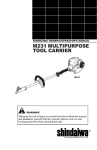
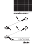
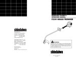
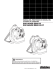
SHINDAIWA OWNER’S/OPERATOR’S MANUAL
M230 MULTIPURPOSE
TOOL CARRIER
M230
■ Read this manual and familiarize yourself with its contents.
■ This machine is designed for cutting grass, weeds and brush. Use only for
designated purpose.
WARNING!
■ Minimize the risk of injury to yourself and others.
■ Always wear eye protection when operating this machine.
■ Do not operate or service this machine unless you clearly understand
■
this manual.
Keep this manual available at all times so that you can reference it
whenever you have a question about the use of this unit.
Part Number 65028-94310 Rev. 8/07
Introduction
Attention Statements
The Shindaiwa 230 series hand-held
power equipment has been designed and
built to deliver superior performance and
reliability without compromise to quality,
comfort, safety or durability.
Throughout this manual are special
“attention statements”.
Shindaiwa engines represent the leading
edge of high-performance engine technology, delivering exceptionally high power
with remarkably low displacement and
weight. As an owner/operator, you’ll soon
discover for yourself why Shindaiwa is
simply in a class by itself!
IMPORTANT!
The information contained in this owner's/operator's manual describes M230
Multipurpose Tool Carrier available at the
time of publication.
Shindaiwa Inc. reserves the right to make
changes to products without prior notice,
and without obligation to make alterations
to units previously manufactured.
WARNING!
A statement preceded by the
triangular attention symbol and the
word “WARNING” contains information that should be acted upon to
prevent serious bodily injury.
CAUTION!
A statement preceded by the word
“CAUTION” contains information
that should be acted upon to prevent
mechanical damage.
IMPORTANT!
A statement preceded by the word
“IMPORTANT” is one that possesses
special significance.
NOTE:
A statement preceded by the word “NOTE”
contains information that is handy to know
and may make your job easier.
Read and follow this manual, make
sure anyone using the trimmer
does likewise. Failure to do so
could result in serious personal
injury or machine failure. Keep
this manual for future reference.
Always wear a hard hat to reduce
the risk of head injuries during
operation of this machine. In addition, always wear eye and hearing
protection. Shindaiwa recommends wearing a face shield as
additional face and eye protection.
Wear heavy duty, non-slip gloves.
Safety tip shoes or boots with
non-slip sole should be worn.
This product conducts electricity.
Keep the product and/or operator
a minimum distance of 15 feet
(4.5 meters) away from electrical sources and power lines.
Keep bystanders at least 50
feet (15 meters) away from the
operating trimmer to reduce the
risk of being struck by falling
objects or thrown debris.
The blades / cutting attachments
are SHARP! Handle with care.
Be aware of the danger
of falling debris.
Contents
PAGE
Introduction................................................ 2
Attention Statements................................. 2
Safety Instructions..................................... 3
Safety Labels............................................... 3
Product Description................................... 4
Specifications.............................................. 4
Assembly and Adjustments....................... 5
Adding/Removing a Tool Attachment..... 5
Mixing Fuel................................................ 6
Filling the Fuel Tank................................. 6
Starting the Engine . ................................. 7
Stopping the Engine.................................. 8
Adjusting Engine Idle................................ 8
Maintenance............................................... 9
Long Term Storage.................................. 11
Troubleshooting Guide........................... 12
IMPORTANT!
The operational procedures described
in this manual are intended to help you
get the most from this unit as well as
to protect you and others from harm.
These procedures are guidelines for safe
operation under most conditions, and are
not intended to replace any safety rules
and/or laws that may be in force in your
area. If you have questions regarding your
230-series hand held power equipment,
or if you do not understand something in
this manual, your Shindaiwa dealer will be
glad to assist you. You may also contact
Shindaiwa, Inc. at the address printed on
the back of this manual.
Safety Instructions
WARNING!
Never operate
power equipment of any
kind if you are tired or if you are under
the influence of alcohol, drugs, medication or any other substance that
could affect your ability or judgement.
Work Safely
WARNING!
Attachments for the Multipurpose Tool
Carrier operate at very high speeds
and can do serious damage or injury if
they are misused or abused. Never allow
a person without training or instruction to
operate this unit!
Never make unauthorized
attachment installations. Do not
use attachments not approved by
Shindaiwa for use on this unit.
Stay Alert
You must be physically and mentally fit to
operate this unit safely.
WARNING!
Use Good Judgement
ALWAYS wear eye protection to shield
against thrown objects.
ALWAYS wear hearing protection
devices when operating this unit.
NEVER operate the engine when
transporting the unit. Make sure cutter
safety guards are in place when transporting this unit.
NEVER operate the engine indoors!
Make sure there is always good ventilation. Fumes from engine exhaust can
cause serious injury or death.
ALWAYS make sure there are no missing
or loose fasteners and that the stop switch
and throttle controls are working properly.
ALWAYS use the proper cutting tool for
the job.
ALWAYS clear your work area of trash
or hidden debris that could be thrown
back at you or toward a bystander
ALWAYS make sure the cutting attachment tool is properly installed and
firmly tightened before operation.
NEVER use a cracked or warped
cutting attachment: replace it with a
serviceable one and make sure it fits
properly.
ALWAYS stop the engine immediately
if it suddenly begins to vibrate or shake.
Inspect for broken, missing or improperly
installed parts or attachments.
ALWAYS keep the unit as clean as
practical. Keep it free of loose vegetation, mud, etc.
NEVER extend trimming line beyond
the length specified for your unit.
ALWAYS hold the unit firmly with both
hands when cutting or trimming, and
maintain control at all times.
ALWAYS keep the handles clean.
ALWAYS disconnect the spark plug wire
before performing any maintenance work.
BEFORE starting the engine make
sure the cutting attachment is not contacting anything.
ALWAYS stop the engine immediately
and check for damage if you strike a
foreign object or if the unit becomes
tangled. Do not operate with broken or
damaged equipment.
Safety Labels
M230
IMPORTANT!
Safety and Operation Information Labels:
Make sure all information labels are
undamaged and readable. Immediately
replace damaged or missing information
labels. New labels are available from your
local authorized Shindaiwa dealer.
Figure 1
Product Description
Using the accompanying illustrations as
a guide, familiarize yourself with this unit
and its various components. See Figure 2.
Understanding your unit helps ensure top
performance, long service life and safer
operation.
M230
WARNING!
Air
Cleaner
Handle
Outer
Tube
Coupler
Throttle
Trigger
Before assembling, make sure you have all
the components required for a complete unit:
■ Engine/Outer tube assembly
■ Handle
■ Kit containing handle mounting bracket
and hardware, this owner/operator's
manual and tool kit for routine maintenance. Tool kits vary by model and
may include a hex wrench set, a spark
plug/screwdriver combination wrench,
and a spanner.
Grip
Ignition
Switch
Do not make unauthorized
modifications or alterations to any of
these units or their components.
Prior to Assembly
Spark
Plug
Throttle Lockout
Lever
Tank Guard
Latch protector
Fuel Tank
Latch
Coupler Screw Knob
Figure 2a
Figure 2
M23002a
IMPORTANT!
The terms “left”, “left-hand”, and “LH”;
“right”, “right-hand”, and “RH”; “front”
and “rear” refer to directions as viewed by
the operator during normal operation.
Specifications
Engine Name . .................................................................................................................................................................................................M230
Engine model................................................................................................................................................................................................... S230
Engine type.................................................................................................................................................... 2-cycle, vertical cylinder, air cooled
Dry weight (less attachments)...........................................................................................................................................................4.2 kg/9.4 lb
Displacement . ............................................................................................................................................................................ 22.5 cc/1.4 cu. in.
Bore x stroke................................................................................................................................................................ 32 x 28 mm/1.25 x 1.10 in.
Engine Speed at Maximum Power Output . ............................................................................................................................. 7,500 rpm (min-1)
Maximum power output................................................................................................................................................................... 0.8 kW/1.1 hp
Engine speed at idling ................................................................................................................................................................ 2,750 rpm (min-1)
Fuel tank capacity............................................................................................................................................................................554 cc/18.7 oz.
Fuel/oil ratio........................................................................................................................................... 50:1 with Shindaiwa 2-cycle Mixing Oil
Carburetor .......................................................................................................................................................................................... Walbro WYL
Ignition .............................................................................................................................................. One piece electronic, transistor-controlled
Spark plug........................................................................................................................................................................................... NGK BMR6A
Air filter....................................................................................................................................................... Non-reversible flocked filter element
Starting method............................................................................................................................................................................................. Recoil
Stopping method ..................................................................................................................................................................................Slide switch
Transmission type . ......................................................................................................................Automatic, centrifugal clutch with bevel gear
Specifications subject to change without notice.
Assembly and Adjustments
Connect the Handle to the Outer Tube.
1. Position the handle on the outer tube as
shown. See Figure 3.
2. Install the mounting bracket with the
socket-head screws. Tighten the screws
finger-tight ONLY at this time.
Throttle Assembly
Socket-head
Capscrews
3. Locate the handle in the best position
for operator comfort (usually about 10
inches ahead of the throttle assembly).
Handle
4. Secure the handle by alternately
tightening the four socket-head screws
in a diagonal or “criss-cross” fashion.
Outer Tube
Mounting Bracket
Figure 3
Installing a Tool Attachment
1. Place the unit and tool assembly on a
clean, flat surface so that both assemblies fit end to end.
Tube Assembly
Latch Protector (extended)
Latch
The unit should be facing up and the
tool assembly should be positioned with
the locking hole in the tube end facing
up. See Figure 4a.
Locking Hole
CAUTION!
Keep the open ends of the tubes
clean and free of impurities!
Coupler Screw Knob
2. Slip off the protective covers from the
ends of both tubes, and loosen the
coupler screw knob.
Coupler
Figure 4a
Coupler
3. Insert the tool assembly into the coupler, with the tool decal facing up, until
the line of the decal is flush with the end
of the coupler.
Tool Assembly
Latch Protector
(lowered)
4. Twist the tool back and forth until you
are sure it snaps in place by the coupler
latch. See Figure 4a.
5. When the two tube halves are locked
together, press down on the springloaded latch protector and tighten the
coupler screw. See Figure 4b.
Coupler Screw Knob
Figure 4b
Removing a Tool Attachment
1. With the unit on a clean, flat surface,
loosen the coupler screw. The springloaded coupler protector should pop up.
Press
Latch
2. Press down on the latch with your
finger or thumb. This releases the
coupler lock. See Figure 5.
3. Pull the tool assembly out of the
coupler.
Figure 5
Mixing Fuel
CAUTION!
Some types of gasoline contain alcohol as an oxygenate. Oxygenated
gasoline may cause increased operating temperatures. Under certain
conditions, alcohol-based gasoline
may also reduce the lubricating
qualities of some 2-cycle mixing
oils. Never use any type of gasoline
containing more than 10% alcohol
by volume! Generic oils and some
outboard oils may not be intended
for use in high-performance engines,
and should never be used in your
Shindaiwa engine.
■ Use only fresh, clean unleaded gasoline
with a pump octane of 87 or higher.
■ Mix all fuel with a 2-cycle
air-cooled
mixing oil that meets or exceeds ISOL-EGD and/or JASO FC classified oils
at 50:1 gasoline/oil ratio.
CAUTION!
This engine is designed to operate
on a 50:1 mixture consisting of
unleaded gasoline and ISO-L-EGD
or JASO FC class 2-cycle mixing oil
only. Use of non-approved mixing
oils can lead to excessive carbon
deposits.
Examples of 50:1 mixing quantities
Gasoline
liters
2.5
5
10
20
-
1
1
1
1
2-cycle mixing oil
milliliters
50
100
200
400
ml
ml
ml
ml
IMPORTANT!
Mix only enough fuel for your immediate
needs! If fuel must be stored longer than
30 days and
oil with fuel stabilizer
is not used, it should first be treated with a
fuel stabilizer such as StaBil™.
Oil is a registered JASO FC
classified oil and also meets or exceeds
ISO-L-EGD performance requirements.
Shindaiwa One is recommended for use
in all Shindaiwa low emissions engines.
Shindaiwa One also includes a fuel
stabilizer.
Filling the Fuel Tank
WARNING!
Minimize the risk of fire!
■ STOP engine before refueling.
■ ALWAYS allow the engine to cool
■
■
before refueling!
Wipe all spilled fuel and move the
engine at least 10 feet (3 meters)
from the fueling point and source
before restarting!
NEVER start or operate this unit if
there is a fuel leak.
■ NEVER start or operate this
■
■
■
unit if
the carburetor, fuel lines, fuel tank
and/or fuel tank cap are damaged.
NEVER smoke or light any fires near
the engine or fuel source!
NEVER place any flammable material near the engine muffler!
NEVER operate the engine without
the muffler and spark arrester in
good working condition.
1. Place the unit on a flat, level surface.
2. Clear any dirt or other debris from
around the fuel filler cap.
3. Remove the fuel cap, and fill the tank
with clean, fresh fuel.
4. Reinstall the fuel filler cap and tighten
firmly.
Starting the Engine
IMPORTANT!
Engine ignition is controlled by a two
position switch mounted on the throttle
housing labeled, “I” for ON or START
and “O” for OFF or STOP.
3. Set the choke lever to the CLOSED
position if engine is cold.
6. When the engine starts, slowly move
the choke lever to the “OPEN” position.
(If the engine stops after the initial
start, close the choke and restart.)
Open
1. Slide the ignition switch to the “I”
position.
Closed
ON
Figure 8
Figure 10
WARNING!
Figure 6
2. Press the primer bulb until fuel can be seen
flowing in the transparent return tube.
23121
The cutting attachment may
start to rotate when the engine is
started. Make sure the cutting
attachment is free of obstructions
before attempting to start the
engine!
4. While holding the outer tube firmly
with left hand, use your other hand to
slowly pull the recoil starter handle
until resistance is felt.
Primer Bulb
Make sure the
cutting attachment is
free of obstructions
Return Tube
Never start the engine from
the operating position.
IMPORTANT!
If the engine fails to start after several
attempts with the choke in the closed
position, the engine may be flooded
with fuel. If flooding is suspected, move
the choke lever to the open position
and repeatedly pull the recoil starter to
remove excess fuel and start the engine.
If the engine still fails to start, refer to the
troubleshooting section of this manual.
When the Engine Starts...
■ After the engine starts, allow the
Figure 7
engine to warm up at idle 2 or 3 minutes before operating the unit.
23117
IMPORTANT!
The primer system only pushes fuel
through the carburetor. Repeatedly
pressing the primer bulb will not flood the
engine with fuel.
WARNING!
■ After the engine is warm, pick
23120
Figure 9
Hold the outer
tube firmly with
left hand
5. When resistance is felt, pull quickly to
start the engine.
CAUTION!
Do not pull the recoil starter to the
end of the rope travel. Pulling the
recoil starter to the end of the rope
travel can damage the starter.
up the
unit and clip on the shoulder strap if so
equipped. See the section on “Operating the Unit with a Shoulder Strap”.
■ Advancing the throttle makes the cut-
ting attachment turn faster; releasing
the throttle permits the attachment to
stop turning.
■ If the cutting attachment continues
to rotate when the engine returns to
idle, carburetor idle speed should be
adjusted. See the section “Adjusting
Engine Idle”.
Stopping the Engine
Idle the engine briefly before stopping
(about 2 minutes), then slide the ignition
switch to the “O” (Engine OFF) position.
OFF
Figure 11
Adjusting Engine Idle
Idle Speed Adjustment
1. Place the unit on the ground, then start
the engine, and then allow it to idle 2-3
minutes until warm.
2. If the attachment rotates when the
engine is at idle, reduce the idle speed
by turning the idle adjustment screw
counter-clockwise. See Figure 12.
If a tachometer is available, the engine idle
speed should be final adjusted to 2,750
(±250) min-1.
Figure 12
The engine must return to idle speed
whenever the throttle lever is released.
Idle speed is adjustable, and must be set
low enough to permit the engine clutch to
disengage the cutting attachment.
WARNING!
The cutting attachment must
NEVER rotate at engine idle! If the
idle speed cannot be adjusted by the
procedure described here, return the
trimmer to your Shindaiwa dealer for
inspection.
IMPORTANT
Carburetor fuel mixture adjustments are
preset at factory and cannot be serviced
in the field.
General Maintenance
Muffler
This unit must never be operated with a
faulty or missing spark arrester or mufler.
Make sure the muffler is well secured and
in good condition. A worn or damaged
muffler is a fire hazard and may also
cause hearing loss.
Spark Plug
WARNING!
Before performing any maintenance, repair or cleaning work on
the unit, make sure the engine and
cutting attachment are completely
stopped. Disconnect the spark plug
wire before performing service or
maintnenance work.
WARNING!
Non-standard parts may not
operate properly with your unit and
may cause damage and lead to
personal injury.
Keep the spark plug and wire connections
tight and clean.
Fasteners
Make sure nuts, bolts, and screws (except
carburetor adjusting screws) are tight.
Daily Maintenance
Prior to each work day, perform the
following:
■ Remove dirt or debris from the engine,
check the cooling fins and air cleaner
for clogging and clean them as necessary.
■ Carefully remove any accumulation of
dirt or debris from the muffler or the
fuel tank. Dirt build-up in these areas
could cause engine overheating, induce
premature wear, or create a fire hazard.
■ Check for loose or missing screws or
components. Make sure the cutting
attachment is securely fastened.
■ Check the entire unit for leaking fuel or
grease.
10-Hour Maintenance
Every 10 hours of operation (more frequently in dusty or dirty conditions):
Loosen Knob
■ Remove the air cleaner element. See
Remove and clean or
replace the element
figure 14. Clean or replace as necessary.
To clean element:
Wash the air filter element thoroughly
in soap and water. Let it dry before
reinstalling the element.
CAUTION!
Never operate the unit if the air
cleaner assembly is damaged or
missing!
Figure 13
10/15-Hour Maintenance
Every 10 to 15 hours of operation:
Clean the spark plug
and check the gap at
the electrode.
■ Remove and clean the spark plug.
Adjust the spark plug electrode gap to
0.024 in./0.6 - 0.7 mm.
If the spark plug must be replaced,
use only an NGK BMR6A or equivalent
resistor type spark plug of the correct
heat range. See Figure 14.
0.024 in.
(0.6 mm)
CAUTION!
Before removing the spark plug,
clean the area around the plug to
prevent dirt and debris from getting
into the engine’s internal parts.
M23016
Figure 14
NOTE:
The NGK BMR6A also meets the requirements for electro magnetic compliance
(EMC).
50-hour Maintenance
Remove and replace the fuel filter
element.
■ Use a hooked wire to extract the fuel
filter from inside the fuel tank. See
Figure 15.
Before reinstalling the new filter element,
inspect the condition of all the fuel system
components (fuel pick-up line, fuel return
line, tank vent line, tank vent, fuel cap and
fuel tank).
CAUTION!
Make sure you do not pierce the fuel
line with the end of the hooked wire.
The line is delicate and can be damaged easily.
10
If damage, splitting or deterioration
is noted, the unit should be removed
from service until it can be inspected or
repaired by a Shindaiwa-trained service
technician.
Hooked
Wire
Figure 15
Filter Element
Muffler Maintenance
Inspect and clean the spark arrestor
screen.
Engine Cover Knob
WARNING!
Engine Cover
Never operate the unit with a
damage or missing muffler or spark
arrester! Operating with a missing or
damaged spark arrester is a fire hazard
and could also damage your hearing.
1. Remove the spark plug boot.
2. Remove the engine cover by loosening
the engine cover knob ) and lifting the
cover from the engine.
3. Remove the spark arrester screen
screw.
4. Remove the spark arrester screen and
clean with a stiff bristle brush.
Muffler
5. Reassemble the spark arrester screen
and engine cover in reverse order.
Spark Arrestor
Retaining Screw
IMPORTANT!
If you note excessive carbon buildup,
consult with an authorized Shindaiwa
servicing dealer.
Spark Arrestor Screen
Figure 16
Long Term Storage
Whenever the unit will not be used for 30
days or longer, use the following procedures to prepare it for storage:
■ Clean external parts thoroughly and apply
a light coating of oil to all metal surfaces.
■ Drain all the fuel from the fuel tank.
IMPORTANT!
All stored fuels should be stabilized with a
fuel stabilizer such as STA-BIL™ , if
oil with fuel stabilizer is not used.
CAUTION!
Gasoline stored in the carburetor for
extended periods can cause hard starting and could also lead to increased
service and maintenance cost.
■ Remove the remaining fuel from the
fuel lines and carburetor:
1. Prime the primer bulb until no more
fuel is passing through.
2. Start and run the engine until stops
running.
3. Repeat steps 1 and 2 until the engine
will no longer start.
■ Before storing the unit, repair or
replace any worn or damaged parts.
■ Remove the air cleaner element from
the carburetor and clean it thoroughly
with soap and water. Let dry and reassemble the element.
■ Store the unit in a clean, dust-free area.
4. Remove the spark plug and pour
about 1/4 ounce of 2-cycle mixing oil
into the cylinder through the spark
plug hole. Slowly pull the recoil
starter 2 or 3 times so oil will evenly
coat the interior of the engine.
5. Reinstall the spark plug.
11
Troubleshooting Guide
What To Check
Does the engine
crank?
Possible Cause
NO
NO
YES
Does the tank contain
fresh fuel of the proper
grade?
Faulty recoil starter.
Fluid in the crankcase.
Consult with an authorized
servicing dealer.
NO
Loose spark plug.
Tighten and re-test.
Excess wear on cylinder, piston,
rings.
Consult with an authorized
servicing dealer.
Fuel incorrect, stale, or
contaminated; mixture incorrect.
Refill with fresh, clean unleaded gasoline
with a pump octane of 87 or higher mixed
with 50:1 Shindaiwa Premium 2-cycle
mixing oil or with an equivalent high quality
2-cycle mixing oil.
Check for clogged fuel filter and/
or vent.
Replace fuel filter or vent as required.
Restart.
The ignition switch is in “O” (OFF)
position.
Shorted ignition ground.
Move switch to “I” (ON) position and
restart.
YES
Is fuel visible and
moving in the return
line when priming?
Remedy
Internal damage.
YES
Good compression?
ENGINE DOES NOT START
NO
YES
Is there spark at
the spark plug wire
terminal?
YES
Check the spark plug.
12
NO
Faulty ignition unit.
Consult with an authorized servicing
dealer.
If the plug is wet, excess fuel may be
in the cylinder.
Crank the engine with the plug removed,
reinstall the plug, and restart.
The plug is fouled or improperly
gapped.
Clean and regap the plug to 0.024 in./
0.6mm-0.7mm. Restart.
The plug is damaged internally or of
the wrong size.
Replace the spark plug. Check the unit
Specifications page for the proper spark
plug for your unit. Restart.
Troubleshooting Guide (continued)
LOW POWER
What To Check
Is the engine overheating?
Engine is rough at all
speeds. May also have black
smoke and/or unburned
fuel at the exhaust.
Possible Cause
Remedy
Operator is overworking the unit.
Cut at slower rate.
Carburetor mixture is too lean.
Consult with an authorized servicing
dealer.
Improper fuel ratio.
Refill with clean fresh unleaded gasoline
with a pump octane of 87 or higher, mixed
with Premium 2-cycle mixing oil at a 50:1
gasoline/oil ratio.
Fan, fan cover, cylinder fins dirty or
damaged
Clean, repair or replace as necessary.
Carbon deposits on the piston or in the
muffler.
Consult with an authorized servicing
dealer
Clogged air cleaner element.
Clean or replace the air filter
Loose or damaged spark plug.
Tighten or replace the spark plug.
Restart. Check the "Specifications" page
in this manual for the correct spark plug
for this unit.
Air leakage or clogged fuel line.
Repair or replace fuel filter and/or
fuel line.
Water in the fuel.
Refill with fresh fuel/oil mixture.
Piston seizure.
Faulty carburetor and/or diaphragm
Consult with an authorized servicing
dealer.
Overheating condition.
Consult with an authorized servicing
dealer.
Improper fuel.
Check fuel octane rating; check for
presence of alcohol in the fuel. Refuel
as necessary.
Engine is knocking.
Carbon deposits in the combustion
chamber.
Consult with an authorized servicing
dealer.
13
Troubleshooting Guide (continued)
ADDITIONAL PROBLEMS
What To Check
Poor acceleration.
Engine stops abruptly.
Engine difficult to shut
off.
Cutting attachment moves
at engine idle.
Excessive vibration.
Attachment will not rotate.
Possible Cause
Clogged air filter.
Clean or replace the air filter.
Clogged fuel filter.
Replace the fuel filter.
Lean fuel/air mixture.
Consult with an authorized servicing
dealer.
Idle speed set too low.
Adjust: 2,750 (±250) min-1.
Switch turned off.
Reset the switch and re-start.
Fuel tank empty.
Refuel. See See "Filling the Fuel Tank"
section of manual.
Clogged fuel filter.
Replace fuel filter.
Water in the fuel.
Drain; replace with clean fuel. See "Filling
the Fuel Tank" section of manual.
Shorted spark plug or loose terminal.
Clean or replace spark plug. Check the
"Specifications" page in this manual for the
proper spark plug for your unit. Tighten the
terminal.
Ignition failure.
Replace the ignition unit.
Piston seizure.
Consult with an authorized servicing
dealer
Ground (stop) wire is disconnected or
switch is defective
Test and replace as required.
Overheating due to incorrect spark
plug
Replace the spark plug. Check the
Specifications page in this manual for
the proper spark plug for your unit.
Overheated engine.
Idle engine until cool.
Engine idle too high.
Set idle: 2,750 (±250) min-1.
Broken clutch spring or worn clutch
spring boss.
Replace spring/shoes as required,
check idle speed.
Loose attachment holder.
Inspect and re-tighten holders securely.
Warped or damaged attachment.
Inspect and replace attachment as
required.
Loose gearcase.
Tighten gearcase securely.
Bent main shaft/worn or damaged
bushings.
Inspect and replace as necessary.
Shaft not installed in powerhead or
gearcase.
Inspect and reinstall as required.
Broken shaft.
Consult with a authorized servicing
dealer.
Damaged gearcase.
14
Remedy
NOTES
15
NOTES
Shindaiwa Inc.
11975 S.W. Herman Road
Tualatin, Oregon 97062
Telephone: 503 692-3070
Fax: 503 692-6696
www.shindaiwa.com
16
Shindaiwa Corporation
Head Office:
6-2-11, Ozuka-Nishi
Asaminami-Ku, Hiroshima
731-3167, Japan
Telephone: 81-82-849-2220
Fax:
81-82-849-2481
©2007 Shindaiwa, Inc.
Part Number 65028-94310
Revision 7/07
Shindaiwa is a registered trademark of Shindaiwa, Inc.
Specifications subject to change without notice.
Manual Del Propietario / Operador Shindaiwa
M230 Porta
Herramienta Multiple
M230
¡ADVERTENCIA!
■ Reduzca al mínimo el riesgo de lesiones, tanto a usted mismo como a otras personas.
■ Lea detenidamente este manual y familiarícese con su contenido.
■ Protéjase los ojos y los oídos siempre que trabaje con esta unidad.
■ Esta máquina está diseñada para cortar setos.
■ No utilice esta máquina ni efectúe trabajos de mantenimiento en ella sin haber
■
comprendido claramente todas las explicaciones de este manual.
Mantenga el manual a su alcance en todo momento, de modo que pueda consultarlo si le surge alguna duda sobre el manejo de la máquina.
Part Number 65028-94310 Rev. 2/07
Introducción
Declaraciones De Seguridad
La Serie 230 de maquinaria manual
Shindaiwa, ha sido disenada y construida
para suministrar un rendimiento superior
sin comprometer calidad, comodidad
ni durabilidad. Los motores Shindaiwa
representan la technologia lider de motores
de alto rendimiento, con excepcional alta
potencia de peso y cilindrada sumamente
bajos. Como proprietario/operario, usted no
tardara en comprobar que Shindaiwa es la
unica maquina en esta clase!
A travéz de este manual se encuentran
“declaraciones de seguridad” especiales..
¡IMPORTANTE!
La información contenida en este manual
del proprietario/operario describe la
Porta Herramienta Multiple M230
disponibles a la fecha de su publicación.
Shindaiwa Inc. se reserva el derecho
de realizar cambios a sus productos sin
previo aviso, y sin la obligación de hacer
modificaciones a máquinas fabricadas
previamente.
¡ADVERTENCIA!
Toda información precedida
por un símbolo triangular de advertencia y la palabra ADVERTENCIA!
contiene información o procedimientos que se deben cumplir para evitar
lesiones.
¡PRECAUCIÓN!
Toda información precedida por la
palabra PRECAUCION! contiene
información que se debe cumplir
para evitar daños mecánicos.
Lea y siga el manual, asegurese de
que quien use esta podadora también
lo lea. En caso de no leerlo y usar
la podadora apropiadamente puede
causarle serias lesiones tanto a
usted como a la maquina. Guarde el
manual para futuras consultas.
Siempre utilice un casco para reducir
el riesgo de lesiones en la cabeza
al momento de utilizar la maquina.
También utilice siempre lentes de
protección así como protector para
los oídos. Shindaiwa recomienda que
utilicen un protector para la cara como
medida de protección adicional.
Utilice guantes para trabajo que
sean antiresbalantes.
¡IMPORTANTE!
Toda información precedida por la palabra
“IMPORTANTE” contiene información
especial y significante.
NOTA:
Toda información precedida por la
palabra “NOTA” contiene información útil
que puede hacer su trabajo más fácil.
Botas de seguridad o botas de
trabajo antirederrapantes también
deben de se usadas.
Estos productos atraen electricidad.
Debe mantenerse la maquina así
como el operador a una distancia
de 4,5 metros de distancia de toda
fuente de electricidad.
La gente debe de permanecer a 15
metros de la maquina cuando esta
en operación, esto para reducir el
riesgo de ser golpeado por objetos
que están siendo cortados.
Las cuchillas o utensilios para cortar son muy “FILOSOS” Manéjelos
con cuidado.
Índice
PAGE
Declaraciones De Seguridad ................... 2
Instrucciones Generales de Seguridad.... 3
Etiquetas de Seguridad.............................. 3
Descripción del Producto.......................... 4
Especificaciones......................................... 4
Ensamblaje y Ajustes................................. 5
Mezcla de Combustible............................. 6
Llenando el Tanque de Combustible....... 6
Arranque del motor................................... 7
Parada del motor........................................ 8
Ajuste de Marcha Mínima del Motor....... 8
Mantenimiento .......................................... 9
Almacenamiento de Largo Plazo............ 11
Guia Diagnostico...................................... 12
¡IMPORTANTE!
El propósito de los procedimientos
operacionales descritos en este manual
es ayudarle a obtener el más alto rendimiento de su máquina y proteger
a usted y a otras personas de sufrir
lesiones. Estos procedimientos son pautas
operativas para una operación segura bajo
la mayoría de condiciones y no tienen el
propósito de substituir las normas y/o
leyes vigentes en su área. Si tiene alguna
pregunta relacionada con su Serie 2510
o si no entiende alguna información
contenida en este manual, consulte a su
distribuidor Shindaiwa, quien le atenderá
con gusto. También puede comunicarse
con Shindaiwa Inc. a la dirección que aparece en la contra portada de este manual.
Tenga cuidado con el escombro que
cae de los árboles o de la maleza.
Instrucciones Generales de Seguridad
¡ADVERTENCIA!
Nunca opere
ninguna máquinaria motorizada si está cansado o si está bajo la
influencia de alcohol, drogas o medicamentos o cualquier otra substancia que
pueda afectar su abilidad y juicio.
Trabaje con cuidado
Los accesorios para la porta herramienta
multiple operan a velocidades altas y
pueden causar daños o lesiones serias si son
malusadas o abusadas. Nunca permita que
una persona sin entrenamiento o instrucción
opere esta unidad !
¡ADVERTENCIA!
Nunca instale accesorios no
autorizados. No use accesorios no
aprobados por Shindaiwa en esta
unidad.
Mantengase Alerta
Debe de estar físicamente y mentalmente
en forma para operar esta máquina con
seguridad.
ADVERTENCIA!
Use Buen Juicio
SIEMPRE use protección para los
ojos como escudo contra objetos
lanzados.
SIEMPRE use proteccion auditiva
cuando opere esta unidad.
NUNCA opere el motor cuando transporte la unidad. Cerciorese de que
los protectores de corte esten en su
lugar cuando transporte la unidad.
NUNCA opere la unidad en el interior! Cerciorese que siempre haya
buena ventilación. El humo o gases
del escape del motor pueden causar
serias lesiones o la muerte.
Siempre verifica que no haya
sujetadores que falta o flojos y que el
interruptor y acelerador están funcionando correctamente.
SIEMPRE use el accesorio de corte
apropiado.
SIEMPRE mantenga su area de
trabajo libre de basura u objetos que
pueden rebotar contra usted o contra
transeúntes.
SIEMPRE cerciore que el accesorio
de corte este propiamente instalado y
firmemente apretado antes de empezar a operar.
NUNCA use un accesorio de corte
quebrado o doblado. Reemplacelo
por uno util y cerciore de que este
propriamente situado.
SIEMPRE pare el motor inmediatamente y revise en busca de daños si
golpea un objeto extraño o si la unidad se enreda. No opere con equipo
dañado o quebrado.
SIEMPRE mantenga la máquina lo
más limpia posible. Mantengala libre de
vegetación, barro, etc.
NUNCA extienda el cable de nylon más
allá de lo especificado para su máquina.
SIEMPRE sujete la máquina firmemente con ambas manos cuando
corte o recorte, y mantenga el control
en todo momento.
SIEMPRE mantenga los mangos
limpios.
SIEMPRE desconente el cable de
bujía antes de hacer mantenimiento
a la máquina.
ANTES de encender el motor, cerciore de que el accesorio de corte no
este en contacto con algo.
SIEMPRE detenga el motor inmediatament y revise en busca de danos,
si golpea un objeto extrano o si la
unidad se enreda. NO opere con
equipo quebrado o danado.
Etiquetas de Seguridad
M230
¡IMPORTANTE!
Etiquetas de Seguridad y de Información
de Operación: Asegurese que toda las
etiquetas estén libres de daños y legibles.
Reemplace inmediatamente etiquetas
dañadas o faltantes. Etiquetas nuevas están
disponibles en su centro de servicio local
autorizado de Shindaiwa.
Figura 1
Descripción del Producto
Use las ilustraciones como guía, familiarícese con esta unidad y sus varios
componentes. Consulte la figura 2.
Conociendo la unidad le ayudará a obtener
alto rendimiento, vida útil más prolongada
y operación con seguridad
M230
Bujía
Seguro del
acelerador
Interruptor de
encendido
¡ADVERTENCIA!
No haga modificaciones
o alteraciones no autorizadas a
ninguna de éstas máquinas ni a sus
componentes.
Agarrador
Mango
Filtro de aire
Tubo exterior
Gatillo del
acelerador
Antes de Ensamblar
Antes de ensamblar, cerciórese de que
tenga todos los componentes necesarios
para armar una máquina completa.
■ Ensamblaje del motor y tubo exterior.
■ Mango
■ Caja conteniendo la abrazadera y piezas
para montar el mango, este manual del
propietario/operador y juego de herramientas para mantenimiento rutinario.
Las cajas de herramientas varian por
modelo y pueden incluir una llave hexagonal, llave bujía y destonillador, y una
llave inglesa.
Tanque
protector
Protector de seguro
Tanque de
combustible
Seguro
Perilla de tornillo
del acoplador
Acoplador
Figura 2a
Figura 2
M23002a
¡IMPORTANTE!
Los términos “izquierda”, “mano izquierda”, y “LH”; “derecha”, “mano derecha”,
y “RH”, “delantera” y “trasera”, indican
direcciones desde el punto de vista del
operador durante la operación normal de
este producto.
Especificaciones
Nombre del modelo.........................................................................................................................................................................................M230
Modello de motor............................................................................................................................................................................................. S230
Tipo de motor........................................................................................................................... 2 tiempos, cilindro vertical, refrigerado por aire
Peso seco (sin accesorios para cortar)..............................................................................................................................................4,2 kg/9,4 lb
Cilindrada .................................................................................................................................................................................... 22,5 cc/1,4 cu. in
Diámetro x Carrera...................................................................................................................................................... 32 x 28 mm/1,25 x 1,10 in.
Régimen de giro a la potencia máxima . ...................................................................................................................................7.500 rpm(min-1)
Potencia Máxima............................................................................................................................................................................... 0.8 kW/1,1 hp
Régimen de giro al ralentí .........................................................................................................................................................2.750 rpm (min-1)
Capacidad del Tanque de Combustible.........................................................................................................................................554 cc/18,7 oz.
Proporción combustible/aceite........................................................................................................................................................................ 50:1
Tipo de Carburador ........................................................................................................................................................................... Walbro WYL
Sistema de Encendido ............................................................................................................................. Electrónico, controlado por transistor
Bujía..................................................................................................................................................................................................... NGK BMR6A
Filtro de Aire........................................................................................................................................................... Filtro de fieltro no reversible
Metodo de Arranque.................................................................................................................................................... Arrancador autorretráctil
Metodo de Parada ...................................................................................................................................................................... Arrancador suave
Tipo de Transmisión........................................................................................Automática, embrague centrífugo con engranajes helicoidales
Especificaciones conforme a cambio sin el aviso
Ensamblaje y Ajustes
Conecte el mango al tubo exterior
1. Posicione el mango sobre el tubo
exterior como se demuestra. Consulte
la figura 3.
Ensamblaje del
acelerador
Tornillos de
cabeza hueca
2. Instale la abrazadera de montaje con los
tornillos de cabeza hexagonal. En este
momento, apriete los tornillos con los
dedos solamente.
Mango
3. Ubique el mango en la mejor posicion
comoda para el operario (usualmente
10 pulgadas aproximadamente hacia
delante del ensamblaje del acelerador).
Tubo Exterior
4. Asegure el mango ajustando alternadamente los cuatro tornillos de cabeza
hueca en forma diagonal o cruzada.
Abrazadera de montaje
Instalacion de una herramienta accesorio
1. Posicione la unidad y el ensamblaje
de herramienta sobre una superficie
limpia y plana, de tal forma que ambos
ensamblajes encajen.
Ensamblaje de tubo
Protector del seguro
(extendido)
Seguro
El ensamblaje de la unidad debe
estar cara arriba y el ensamblaje de la
herramienta debe estar posicionado con
el hoyo del seguro en el tubo con cara
arriba. Consulte la figura 4a.
Hoyo de
seguro
2. Retire las cubiertas protectoras de a bos
tubos y afloje la perilla del tornillo del
acoplador.
¡PRECAUCIÓN!
Pernillo de tomillo del
acoplador
Figura 4a
Acoplador
Mantenga los hoyos de los tubos
limpios y libre de impurezas!
Protector del seguro
(rebajado)
3. Inserte el ensamblaje del herramienta
en el acoplador, con la calcomania de la
herramienta cara arriba, hasta que la
linea de la calcomania este junto al final
del acoplador.
4. Mueva la herramienta de lado a lado
hasta que este seguro de que encaje en
lugar a travez del seguro del acoplador.
Consulte la figura 4a
Ensamblaje de
herramienta
Acoplador
Perilla de tornillo del
acoplador
Figura 4b
5. Cuando ambos tubos esten intercalados,
presione hacia abajo el protector de
seguro con resorte y apriete el tornillo
del acoplador. Consulte la figura 8.
Retirando una herramienta accesorio
1. Con la unidad sobre una superficie
limpia y plana, afloje el tornillo del
acoplador. El protector de seguro con
resorte debe salir.
Presione el
seguro
2. Presione el seguro hacia abajo con
su dedo. Esto libera el seguro del
acoplador. Consulte la figura 5.
3. Jale el ensamblaje de la herramienta
fuera del acoplador.
Figura 5
Mezcla de Combustible
¡PRECAUCIÓN!
¡PRECAUCIÓN!
Algunas gasolinas contienen alcohol
como un oxigenante. Combustibles
oxigenados pueden aumentar la
temperatura del motor durante su
funcionamiento. Bajo ciertas condiciones, combustible con alcohol
puede reducir la calidad lubricante
de algunos aceites de mezcla.
Nunca use ningún combustible que
contenga más de 10% de alcohol
por volumén! Aceites genéricos y
algunos aceitespara motores fuera
de borda puedaque no sean para el
uso en motoresde 2 tiempos, de alto
rendimiento, y no deben ser usados
en su motor Shindaiwa!
Este motor ha sido diseñado para
funcionar únicamente con una
mezcla de 50:1 de gasolina sin
plomo y aceite de mezcla Premium
para motores de dos tiempos. La
utilización de aceites de mezcla no
autorizados puede incrementar los
costes de mantenimiento y los daños
en el motor.
■ Use solamente gasolina fresca, limpia
y sin plomo, con índice de octanaje de
87 o superior.
■ Mezcle todo el combustible con aceite
de mezclar para motores de 2 tiempos
enfriados por aire que cumpla o exceda
aceites clasificados ISO-L-EDG y/o
JASO FC a proporción de 50:1 gasolina/aceite.
Ejemplos de cantidades de mezcla a proporción de 50:1
Gasolina
liters
2,5
5
10
20
-
1
1
1
1
Mezclar para motores
de 2 tiempos
milliliters
50
100
200
400
ml
ml
ml
ml
¡IMPORTANTE!
Mezcle solamente el combustible necesario para uso inmediato! De ser necesario
almacenar el combustible por más de
30 días, y si no se está usando aceite
con estabilizador de combustible,
entonces el combustible debe ser tratado
primero con un estabilizador como por
ejemplo STA-BIL™.
El aceite
es un aceite registrado de
JASO FC clasificado y tambien cumple o
excede los requisitos de rendimiento de
ISO-L-EGD. Shindaiwa One es recomendado para el uso en todo los motores
Shindaiwa de baja emisión. Shindaiwa
One tambien incluye el estabilizador de
combustible.
Llenando el Tanque de Combustible
¡ADVERTENCIA!
Disminuya el riesgo de
incendios!
■ Nunca encienda u opere esta
■ Pare el motor antes de volver a
■
■
■
llenar el tanque.
Siempre deje enfriar el motor antes
de volver a llenar el tanque!
Limpie todo derrame de combustible y
aleje el motor por lo menos 10 pies (3
metros) del depósito de combustible
antes de volver a prender el motor!
Nunca comienze u opere esta
máquina si existe una périda de
combustible.
■
■
■
máquina si el carburador, líneas de
combustible y/o tapa de tanque o
tanque de combustible se encuentran dañados.
Nunca fume o encienda fuegos
cerca del motor o del combustible!
Nunca coloque material inflamable
cerca del silenciador del motor!
Nunca opere el motor sin antes
comprobar que el silenciador y el
guardachispas estén funcionando
adecuadamente.
1. Posicione la maquina sobre una superficie plana y nivelada.
2. Retire cualquier suciedad o despojos
alrededor de la tapa de combustible.
3. Retire la tapa de combustible y llene el
tanque con combustible fresco y limpio.
4. Reinstale la tapa de combustible y
apriete firmemente.
Arranque del motor
¡IMPORTANTE!
El encendido del motor está controlado
por un interruptor de dos posiciones
montado en el mango del acelerador
indicado “I” (encendido o arranque) y “O”
(apagado o pare).
1. Deslice el interruptor hacia la posición
“I” (motor encendido).
3. Posicione la palanca del cebador en la
posición CLOSED (cerrado) si el motor
está frío.
6. Cuando arranque el motor, mueva
despacio la palanca del cebador a la
posición “OPEN” (abierto). Consulte la
figura 18. (Si el motor para después del
arranque inicial, cierre la palanca del
cebador y vuelva arrancar).
Cerrado
Abierto
Encendido
Figura 8
¡ADVERTENCIA!
El accesorio de corte se
moverá cuando arranque el motor.
Manténgase alejado del accesorio
de corte al arrancar el motor.
Figura 6
2. Presione la bombilla de cebado hasta
que vea pasar combustible por el tubo
de retorno transparente.
4. Mientras sostiene el tubo exterior
firmemente con una mano, jale despacio la cuerda del arrancador recular
hasta que sienta resistencia.
Cerciórese de que
el accesorio de
corte esté libre de
obstrucciones!
Bombilla de
cebado
23121
¡ADVERTENCIA!
Nunca arranque el motor
desde la posición de operación.
¡IMPORTANTE!
Si el motor falla en arrancar después de
varios intentos con la palanca del cebador
en posicion cerrada, puede que el motor
esté ahogado con combustible. Si esto se
sospecha, mueva la palanca del cebador a
la posición abierta y repetidamente jale el
arrancador recular para remover el exceso
de combustible y para arrancar el motor. Si
aún falla en arrancar el motor, consulte el
guía diagnóstico de este manual.
Cuando arranca el motor…
Tubo de Retorno
Figura 7
¡IMPORTANTE!
23117
La bomba de cebado solamente empuja
combustible a travéz del carburador. Presionando repetidamente la bomba de cebado
no ahogará el motor con combustible.
Figura 10
23120
Figura 9
Al encender el
motor, mientras
sostiene el tubo
exterior firmemente
con una mano
5. Cuando sientas la resistencia, luego jale
rápidamente para arrancar el motor.
CAUTION!
No jale el arrancador recular hasta
el final de la cuerda. De lo contrario,
puede dañar el arrancador.
■ Después de que arranque el motor,
permita que caliente en marcha
mínima por 2 ó 3 minutos antes de
usar la máquina.
■ Después de que caliente el motor,
levante la máquina y asegure el arnés
si así está equipada. Consulte la
página 11.
■ Adelantando el acelerador hace que
el accesorio de corte gire más rápido;
liberando el acelerador permite que el
accesorio pare de girar.
■ Si el accesorio de corte continua
girando cuando el motor regresa a
marcha mínima, la velocidad mínima
del carburador debe ser ajustada.
(Consulte “Ajuste de Marcha Mínima”
a continuación).
Parada del motor
APAGADO
Ponga el motor en marcha mínima por
dos o tres minutos antes de apagarlo,
luego deslice el interruptor de ignición a
la posición “O” (motor apagado).
Figura 11
Ajuste de Marcha Mínima del Motor
Ajuste de marcha mínima
1. Coloque el aparato en el suelo, luego
encienda el motor y déjelo funcionar en
marcha mínima durante 2 ó 3 minutos
hasta que caliente.
2. Si el accesorio de corte gira mientras el
motor está en marcha mínima, reduzca
la marcha minima, girando el tornillo
de ajuste de marcha mínima en el
sentido contrario a las agujas del reloj.
Consulte la figura 12.
Figura 12
El motor debe retornar a marcha mínima
cuando la palanca del acelerador es
liberada. La marcha mínima es ajustable
y debe ser suficientemente mínima para
permitir que el embrague del motor libere
el accesorio de corte.
Si tiene un tacómetro disponible, la
marcha mínima se debe ajustar a 2750
(±250) min-1.
¡ADVERTENCIA!
El accesorio de corte
NUNCA debe girar en velocidades
mínimas! Si la marcha mínima no
puede ser ajustada por el procedimiento descrito aquí, entronces
devuelva la podadora a su distribuidor Shindaiwa para inspección.
¡IMPORTANTE!
Los ajustes de mezcla de carburador son
prefijados en la fábrica y no pueden ser
cambiados en el campo.
Mantenimiento General
Silenciador
Esta máquina nunca debe ser operada con
un guardachispas o silenciador defectuoso
o faltante. Cerciórese de que el silenciador
esté bien asegurado y en buena condición.
Un silenciador usado o dañado es un riesgo
de incendio y puede causar la perdida de
audición.
¡ADVERTENCIA!
Antes de efectuar
mantenimiento, reparación o limpieza
de la máquina, cerciórese de que
el motor y el accesorio de corte
estén completamente detenidos.
Desconecte el cable de bujía antes de
efectuar servicio de mantenimiento.
¡ADVERTENCIA!
Los repuestos no estándar
puedan que no operen propiamente
con su máquina y pueden causar
daño y conducir a una lesión personal.
Bujía
Mantenga la bujía y las conexiones de
cable apretadas y limpias.
Sujetadores
Cerciórese de que las tuercas, pernos y
tornillos (a excepción de los tornillos de
ajuste del carburador) estén apretados.
Mantenimiento Diario
Antes de cada día de trabajo, efectúe
lo siguiente:
■ Retire toda suciedad y despojo del motor,
revise las aletas de enfríamiento y el filtro
de aire y límpielos de ser necesario.
■ Cuidadosamente, retire cualquier acumulación de suciedad o despojo del silenciador y del tanque de combustible. La
acumulación de suciedad en dichas áreas
puede ocasionar el sobrecalentamiento
del motor, inducir el gasto prematuro o
crear un riesgo de incendio.
■ Revise que no falten tornillos y que
no estén flojos. Cerciórese de que el
accesorio de corte esté firmemente
asegurado.
■ Revise la máquina entera en busca de
goteo de combustible o grasa.
Cada 10 horas mantenimiento
Cada 10 horas de operación (más
frecuentemente bajo condiciones sucias o
polvorientas):
Aflojando el tornillo
Limpie o reemplace el
elemento del filtro de aire
como sea necesario
■ Retire el elemento del filtro de aire.
Consulte la figura 13. Limpie o reemplace como sea necesario.
Para lavar el elemento:
Lavelo meticulosamente con agua
y jabón. Deje que seque antes de
reinstalarlo.
¡PRECAUCIÓN!
No opere esta máquina si el filtro
de aire está sucio, dañado o si está
húmedo.
Figura 13
Cada 10 - 15 horas mantenimiento
■ Retire y limpie la bujía. Ajuste la distan-
Limpie la bujía y
revise la distancia del
electrodo.
cia del electrodo a 0.6 -0.7 mm./0.024 in.
Si la bujía necesita ser reemplazada, use
solamente una bujía BPMR6A o una
bujía equivalente con resistencia al calor
correcta. Consulte la figura 14.
(0.6 mm)
0.024 in.
¡PRECAUCIÓN!
Antes de retirar la bujía, limpie alrededor de la misma para evitar que
entre polvo o suciedad a las partes
internas del motor.
M23016
Figura 14
NOTA :
La BPMR6A tambíen cumple con los
requisitos de la regulación de electro
mangnéticos (EMC).
Cada 50 horas mantenimiento
Retire y reemplace el elemento del filtro.
■ Use un gancho de alambre para extraer
el filtro de combustible del tanque de
combustible.
Antes de reinstalar el filtro, inspeccione
la condición de todo los componentes del
sistema de combustible (manguera de
alimentacion, manguera del ventilador,
ventilador, tapa y tanque).
¡PRECAUCIÓN!
Asegure de no perforar la tuberia de
combustible con la punta del gancho
de alambre, pués esta línea es delicada y se puede dañar fácilmente.
10
Si descubre daños, quebraduras o deteriorización, retire la unidad de operación
hasta que pueda ser inspeccionada o
reparada por un técnico de servicio
entrenado por Shindaiwa.
Gancho de
alambre
Figura 15
Filtro de
combustible
Mantenimiento del silenciador
Cada 135 horas de operación, retire y
limpie el silenciador.
Perilla de la tapa
del motor
¡ADVERTENCIA!
Tapa del motor
Nunca opere la máquina con
un silenciador o guardachispas dañado
o faltante! De lo contrario, puede ser
un riesgo de incendio y podría también
causar daños a sus oidos.
1. Retire el capuchón de bujía.
2. Aflojando la perilla de la tapa del motor
(la pernilla se captura) y retire la tapa
del motor. Consulte la figura 15.
3. Retire el tornillo de la maya del
guardachispas.
Silenciador
4. Retire la maya del guardachispas
y limpie con un cepillo de cerdas
gruesas.
5. Vuelva a ensamblar el guardachispas
y la tapa del motor en forma reversa al
order de desemblaje.
Tornillos del silenciador
¡IMPORTANTE!
Si nota acumulación excesiva de carbón,
consulte con su centro de servicio o
distribuidor autorizado Shindaiwa.
Guardachispas
Figura 16
Almacenamiento de Largo Plazo
Cada vez que la máquina no va a
ser usada por 30 días o más, siga los
siguientes procedimientos para preparar
su almacenamiento:
■ Limpie las partes externas y aplique
una capa ligera de aceite a todas las
superficies metálicas.
■ Drene todo combustible en el tanque.
¡IMPORTANTE!
Todo combustible almacenado debe
estar estabilizado con un estabilizador de
combustible tal como STA-BIL™, l menos
que use aceite
con estabilizador de
combustible.
■ Retire el resto del combustible en las
■ Antes de almacenar la máquina, repare
1. Empuje la bombilla de cebado hasta
que el combustible deje de pasar.
■ Retire el elemento del filtro de aire y
tuberias de combustible y carburador:
2. Arranque y mantenga prendido el
motor hasta que pare de funcionar.
3. Repita los pasos 1 y 2 hasta que el
motor ya no arranque.
4. Retire la bujía y vierta aproximadamente 7 ml./.25 de onza de aceite de
mezcla para motores de 2 tiempos en
el cilindro a través del agujero de la
bujía. Lentamente jale el arrancador 2
ó 3 veces para que el aceite se aplique
uniformemente en el interior del motor.
o cambie cualquier pieza dañada o
gastada.
limpielo minuciosamente con agua y
jabón. Deje que seque y vuelva a ensamblar el elemento.
■ Almacene la máquina en un sitio limpio
y libre de polvo.
5. Reínstale la bujía.
¡PRECAUCIÓN!
Gasolina almacenada en el carburador por periódos largos puede
causar un arranque duro y puede
conducir a un aumento en costo de
servicio y mantenimiento.
11
Guia Diagnostico
El Motor No Arranca
Qué revisar
¿Arranca el motor?
Posible causa
NO
NO
SÍ
¿Contiene el tanque
combustible fresco y con el
octanaje correcto?
Líquido en el cárter.
Consulte a un agente de servicio de Shindaiwa.
Daños internos.
SÍ
¿Hay buena compresión?
Arrancador autorretráctil defectuoso.
Remedio
NO
Bujía suelta.
Apriete y pruebe otra vez. Consulte con un
agente de servicio autorizado.
Desgaste excesivo en el cilindro, el pistón
o los anillos.
Consulte a un agente de servicio de Shindaiwa.
Combustible incorrecto, viejo o
contaminado; mezcla incorrecta.
Rellene con gasolina sin plomo, reciente y limpia con
un octanaje de 87 o superior, mezclada con aceite
Premium de Shindaiwa para motores de dos tiempos
en una proporción gasolina/aceite de 50:1.
SÍ
¿Puede verse combustible
moviéndose en la línea de
retorno al cebar?
NO
SÍ
NO
¿Hay chispas en el terminal
del cable de la bujía?
Revise el filtro de combustible y el
ventilador en busca de obstrucciones.
Reemplace el filtro de combustible o la válvula
de presión según sea necesario. Vuelva a
arrancar.
El interruptor de encendido está en
posición de apagado “O”.
Lleve el interruptor a la posición de
encendido “I” y reinicie.
Conexión a tierra defectuosa.
Unidad de encendido defectuosa.
Consulte a un agente de servicio de
Shindaiwa.
Si la bujía está húmeda, puede habe
exceso de combustible en el cilindro.
Retire la bujía y arranque el motor, vuelva a
colocar la bujía y arranque de nuevo.
La bujía está obstruida o tiene una
separación de electrodos incorrecta.
Limpie y vuelva a calibrar la bujía a 0,6 ~
0,7 mm./0.024 in. Vuelva a arrancar.
La bujía puede tener daños internos o es
del tamaño equivocado.
Reemplace la bujía. Consulte la sección
"Especificaciones" para la bujía correcta. Vuelva
a arrancar.
SÍ
Compruebe la bujía.
12
Guia Diagnostico (continuación)
Qué revisar
¿Se sobrecalienta el
motor?
El motor funciona
bruscamente a cualquier
velocidad. También puede
que salga humo negro o
combustible no quemado
por el escape.
BAJA POTENCIA
Posible causa
Remedio
Unidad sobrecargada por el usuario.
Corte más despacio.
La mezcla del carburador es muy pobre.
Consulte con un agente de servicio autorizado.
Proporción de combustible
inapropiada.
Rellene con gasolina sin plomo, reciente y limpia
con un octanaje de 87 o superior, mezclada con
aceite Premium de Shindaiwa para motores de
dos tiempos en una proporción gasolina/aceite
de 50:1.
Ventilador, tapa del ventilador o aletas del
cilindro sucios o dañados.
Limpiar, reparar o sustituir en caso
necesario.
Depósitos de carbonilla en el pistón o el
silenciador.
Consulte con un agente de servicio
autorizado.
Filtro de aire obstruido.
Limpie o reemplace el filtro de aire.
Bujía suelta o dañada.
Apriete o cambie la bujía. Consulte la
sección "Especificaciones" para la bujía
correcta. Vuelva a arrancar.
Fuga de aire o conducto de combustible
obstruido.
Repare o cambie el filtro o el conducto de
combustible.
Agua en el combustible.
Vuelva a llenar de mezcla reciente de
combustible y aceite.
Pistón gripado.
Consulte con un agente de servicio
autorizado
Carburador y/o diafragma defectuoso.
Sobrecalentamiento.
Consulte con un agente de servicio
autorizado
Combustible inadecuado.
Revise el índice de octanaje del
combustible; revise si el combustible
contiene alcohol. Reposte cuando sea
necesario.
El motor golpea.
Depósitos de carbonilla en la cámara de
combustión.
Consulte con un agente de servicio
autorizado.
13
Guia Diagnostico (continuación)
Otros problemas
Qué revisar
Deficiente aceleración.
El motor se detiene
abruptamente.
Difícil apagado del motor.
El accesorio de corte se mueve
al ralentí del motor.
Excesiva vibración.
El accesorio no gira.
Posible causa
Filtro de aire obstruido.
Limpie o reemplace el filtro de aire.
Filtro de combustible obstruido.
Cambie el filtro de combustible.
Mezcla de combustible/aire muy pobre.
Consulte con un agente de servicio
autorizado.
Ralentí ajustado muy bajo.
Ajuste: 2.750 (±250) min-1.
Interruptor en posición de apagado.
Restablezca el interruptor y vuelva a
arrancar.
Tanque de combustible vacío.
Reposte combustible. Consulte la sección "Llenando
el Tanque de Combustible".
Filtro de combustible obstruido.
Cambie el filtro de combustible.
Agua en el combustible.
Drene; cambie con combustible limpio. Consulte
la sección "Llenando el Tanque de Combustible"..
Bujía defectuosa o terminal flojo.
Limpie o reemplace la bujía. Consulte la
sección "Especificaciones" para la bujía
correcta. Apriete el terminal. .
Fallo en el sistema de encendido.
Reemplace el sistema de encendido.
Pistón gripado
Consulte con un agente de servicio
autorizado.
Cable de conexión a tierra (detenido)
desconectado o llave defectuosa.
Pruebe y reemplace según sea necesario.
Sobrecalentamiento debido a bujía
incorrecta.
Reemplace la bujía con una NGK BMR6A.
Motor sobrecalentado.
Deje el motor al ralentí hasta que se enfríe.
Ralentí demasiado alto.
Fije el ralentí: 2.750 (±250) min-1.
Resorte del embrague roto o resalte
desgastado.
Reemplace muelle/zapatas según sea
necesario; compruebe el ralentí.
Soporte del accesorio suelto.
IInspeccione y vuelva a apretar los soportes con
firmeza.
Accesorio torcido o dañado.
Examine y cambie el accesorio según sea
necesario.
Caja de engranajes suelta.
Apriete la caja de engranajes con firmeza.
Eje central doblado, cojinetes desgastados
o dañados.
Examine y cambie según sea necesario.
Eje no instalado en el bloque motor o la caja
de engranajes.
Examine y vuelva a instalar según sea necesario.
Eje roto.
Consulte con un agente de servicio
autorizado.
Caja de engranajes dañada.
14
Remedio
NOTES
15
NOTES
Shindaiwa Inc.
11975 S.W. Herman Road
Tualatin, Oregon 97062
Telephone: 503 692-3070
Fax: 503 692-6696
www.shindaiwa.com
16
Shindaiwa Corporation
Head Office:
6-2-11, Ozuka-Nishi
Asaminami-Ku, Hiroshima
731-3167, Japan
Telephone: 81-82-849-2220
Fax:
81-82-849-2481
©2007 Shindaiwa, Inc.
Part Number 65028-94310
Revision 7/07
Shindaiwa is a registered trademark of Shindaiwa, Inc.
Specifications subject to change without notice.