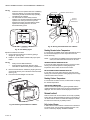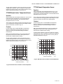
1
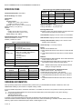
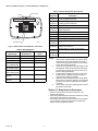
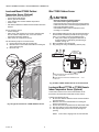
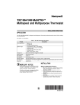
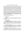
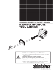
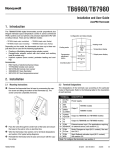
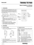
TB7220 COMMERCIALPRO™
Programmable Thermostat
PRODUCT DATA
The TB7220 provides temperature control for gas, oil, electric
and heat pumps for up to 2 heat, 2 cool systems.
FEATURES
• Large, clear display with backlight shows the current
and set temperature and time—even in the dark.
• Menu-driven programming make setup effortless.
• Beautiful ergonomic design is smart and sophisticated
to match your customers’ lifestyle.
• Real-time clock keeps time during power failures and
automatically updates to daylight savings.
• “Saving Changes” notification lets you know when the
schedule changes have been saved.
APPLICATION
• Change reminders let you know when to replace the
batteries.
The TB7220 COMMERCIALPRO™ 7000 Programmable
Thermostat is an effortless, seven-day programmable
thermostat that provides universal system compatibility,
precise comfort control and is easy-to-program.
• Holiday Override options allow you to override the
program schedule, as desired.
• Speedy same-schedule programming—no need to
copy multiple days.
• Armchair programming allows you to remove the
Contents
Application......................................................................... 1
Specifications .................................................................... 2
Ordering Information ......................................................... 2
Installation ......................................................................... 4
Wiring ................................................................................ 5
Installer Setup ................................................................... 12
Operation........................................................................... 17
Troubleshooting (Table 11) ................................................ 22
63-2635-03
TB7220 COMMERCIALPRO™ PROGRAMMABLE THERMOSTAT
SPECIFICATIONS
Table 3. Energy-saving Default Program Settings.
Setpoints
Schedule
Period
Thermostat Description: See Table 1.
Time
Heat
Cool
Electrical Ratings: See Table 2.
Occ1
8:00am
70°F (21°C)
75°F (24°C)
Temperature:
Ratings:
Operating Ambient:
TB7220: 0°F to 120°F (-18°C to 49°C).
C7089U, C7189U: 5% to 95%.
Shipping: -30 °F to 150 °F (-34.4°C to 65.6°C).
Display Accuracy: ±1°F (±0.5°C).
Setpoint:
Range:
Heating: 40°F to 90°F (4°C to 32°C).
Cooling: 50°F to 99°F (10°C to 37°C).
Default Settings: See Table 3.
Unocc1
10:00pm
55°F (10°C)
85°F (29.5°C)
Occ2
—
—
—
Unocc2
—
—
—
Humidity Ratings (RH, non-condensing):
TB7220 Thermostat: 5% to 90%.
C7089U, C7189U: 5% to 95%.
Description
Powering
methods
• Battery only
• 24 Vac only
• 24 Vac with battery backup
System types
(up to
2 heat/2 cool)
• Gas or electric heat with air conditioning
• Warm air, hot water, high-efficiency
furnaces, and heat pumps
• Heat only
• Heat only with fan
• Cool only
Changeover
Manual or Auto changeover selectable
System setting
Heat-Off-Cool-Auto
Fan setting
Auto-On
Table 2. Electrical Ratings
Terminal
Voltage
(50/60 Hz)
Interstage Differential:
Droopless control. Once the first stage is running at 90% load,
the thermostat energizes the second stage.
Cool Indication: Displays “Cool On” when Cool is activated.
Heat Indication: Displays “Heat On” when Heat is activated.
Table 1. Thermostat Description.
Feature
Cycle Rates (at 50% Load):
Heating: Selectable 1 - 12 cycles per hour.
Cooling: Selectable 1 - 6 cycles per hour.
Running Current
W (Heating)
20 - 30 Vac
0.02 - 1.0A
Y (Cooling)
20 - 30 Vac
0.02 - 1.0A
G (Fan)
20 - 30 Vac
0.02 - 0.60A
A (Economizer/TOD)
20 - 30 Vac
0.02 - 1.0A
Auxiliary Heat Indication: Displays “Aux. Heat On” when
Auxiliary Heat is activated.
Clock Accuracy: ±1 minute per month.
Finish:
TB7000: Premier White® color.
C7189U Wall Mount Remote Indoor Sensor: Premier White®
color.
T7770A Wall Mount Remote Indoor Sensor: Premier White®
color.
Batteries:
Two replaceable AA alkaline batteries: Power thermostat when
24 Vac common is not used.
Non-replaceable lithium battery with ten-year life: Under normal conditions holds calendar and time settings.
NOTE: Alkaline batteries keep calendar and time if lithium
battery is no longer functional.
Resistance Characteristics of Remote Sensors:
C7089U Outdoor Sensor: 10K ohm NTC.
C7189U Remote Indoor Sensor: 10K ohm NTC.
C7772 Flush-Mount Remote Indoor Sensor: 20K ohm NTC.
T7770A1006 Wall-Mount Remote Indoor Sensor: 20K ohm
NTC.
T7770A3002 Wall-Mount Remote Indoor Sensor: 10K ohm
NTC.
ORDERING INFORMATION
When purchasing replacement and modernization products from your TRADELINE® wholesaler or distributor, refer to the
TRADELINE® Catalog or price sheets for complete ordering number.
If you have additional questions, need further information, or would like to comment on our products or services, please write or
phone:
1. Your local Honeywell Automation and Control Products Sales Office (check white pages of your phone directory).
2. Honeywell Customer Care
1885 Douglas Drive North
Minneapolis, Minnesota 55422-4386
In Canada—Honeywell Limited/Honeywell Limitée, 35 Dynamic Drive, Scarborough, Ontario M1V 4Z9.
International Sales and Service Offices in all principal cities of the world. Manufacturing in Australia, Canada, Finland, France,
Germany, Japan, Mexico, Netherlands, Spain, Taiwan, United Kingdom, U.S.A.
63-2635—03
TB7220 COMMERCIALPRO™ PROGRAMMABLE THERMOSTAT
Calibration (TB7220, C7089U, C7189U, T7770A):
No field calibration required.
Mounting Means:
TB7220: Direct wall-mount using mounting screws and
anchors provided. Fits standard vertical or horizontal
2 in. x 4 in. junction box.
C7089U: Mounts outside of living space with mounting clip and
screws provided.
C7189U, T7770A: Mounts directly on the wall using mounting
screws and anchors provided. Fits a vertical 2 x 4 in. junction box.
1
LEVEL
LEVEL
6-7/8 IN. (175 MM)
BRACKET
UP
5 IN.
(127 MM)
Cover Plate:
32003796-001 Cover Plate is used to cover marks left on the
wall by the old thermostat.
2
Dimensions:
TB7220 Thermostat: See Fig. 1.
C7089U Outdoor Sensor Mounting Clip: See Fig. 3.
C7189U Remote Indoor Sensor: see Fig. 5.
T7770A: See Fig. 4.
32003796-001 Cover Plate: See Fig. 2.
2
MEDIUM COVER PLATE
8-5/16 IN. (211 MM)
UP
6 IN.
(152 MM)
2
2
LARGE COVER PLATE
THERMOSTAT
AND WALLPLATE
6 (152)
1 BRACKET FOR MOUNTING ON JUNCTION BOX NOT INCLUDED
WITH COVER PLATE.
2 USE BOTTOM MOUNTING HOLES.
M13669
1-3/8
(35)
Fig. 2. 32003796-001 Cover Plate dimensions in in. (mm).
1-1/2 (38)
3-3/4
(95)
M13668
Fig. 1. TB7220 Thermostat
dimensions in in. (mm).
M4488
Fig. 3. C7089U Outdoor Sensor Mounting Clip
dimensions in in. (mm).
3
63-2635—03
TB7220 COMMERCIALPRO™ PROGRAMMABLE THERMOSTAT
4.
After installation is complete, check out product
operation as provided in these instructions.
KNOCKOUTS FOR
EUROPEAN APPLICATIONS
2-3/8
(60)
STANDARD
UTILITY
CONDUIT
BOX (2 X 4)
MOUNTING
HOLES
CAUTION
Electrical Shock or Equipment Damage Hazard.
Can shock individuals or short equipment
circuitry.
Disconnect power supply before installation.
5-1/16
(128)
Select Thermostat Location
Select a location for the thermostat about 5 ft (1.5m) above the
floor in an area with good air circulation at average
temperature. See Fig. 6.
2-3/8 (60)
3-3/16 (80)
15/16
(23)
M22936
Fig. 4. T7770A dimensions in in. (mm).
YES
NO
NO
5 FEET
[1.5 METERS]
NO
4-5/8
(117)
M22258
Fig. 6. Select thermostat location.
2-3/4 (70)
FRONT VIEW
M4465
Do not install the thermostat where it can be affected by:
— Drafts or dead spots behind doors and in corners.
— Hot or cold air from ducts.
— Radiant heat from sun or appliances.
— Concealed pipes and chimneys.
— Unheated (uncooled) areas such as an outside wall behind
the thermostat.
1-1/8
(29)
SIDE VIEW
Fig. 5. C7189U Indoor Sensor dimensions in in. (mm).
Separate Wallplate from Thermostat
MERCURY NOTICE
1.
If this control is replacing a control that contains
mercury in a sealed tube, do not place your old
control in the trash. Dispose of properly.
Separate the wallplate from the thermostat. See Fig. 7.
WALLPLATE
WIRE HOLE
Contact your local waste management authority
for instructions regarding recycling and the proper
disposal of an old control.
INSTALLATION
When Installing this Product...
1.
2.
3.
Read these instructions carefully. Failure to follow them
could damage the product or cause a
hazardous condition.
Check ratings given in instructions and on the product to
ensure the product is suitable for your application.
Installer must be a trained, experienced service
technician.
63-2635—03
4
THERMOSTAT
M22267
Fig. 7. Separate wallplate from thermostat.
TB7220 COMMERCIALPRO™ PROGRAMMABLE THERMOSTAT
Install Wallplate (See Fig. 8)
Mount the thermostat horizontally on the wall:
1. Pull the wires through the wire hole on the wallplate.
2. Position the wallplate on the wall with the arrow pointing
up. Level the wallplate for appearance only.
3. Use a pencil to mark the mounting holes.
4. Remove the wallplate from the wall and drill two 3/16 in.
holes in the wall (if drywall) as marked. For firmer
material such as plaster, drill two 7/32 in. holes. Tap the
wall anchors (provided) into the drilled holes until flush
with the wall.
5. Pull the wires through the wire hole on the wallplate and
position the wallplate over the wall anchors.
6. Insert the mounting screws into the wall anchors and
tighten.
NOTES:
—
—
1.
Refer to Table 5 for terminal designation
descriptions.
See Fig. 12 through 21 for wiring diagrams for
specific equipment applications.
Select set of terminal identifications that correspond to
your system type (conventional or heat pump). See Fig. 9.
HEAT PUMP
CONVENTIONAL
C
G
Y
O/B
RC
WALL
R
WIRES THROUGH WALL
AND WIRE SLOT
C
G
Y
W
RC
1
R
W2
Y2
A
S1
S2
SCREW
TERMINALS
WALL
ANCHORS (2)
1
W1
Y2
S1
S2
M13663
FACTORY INSTALLED JUMPER.
Fig. 9. Terminal identifications for system type.
2.
3.
MOUNTING
HOLES
MOUNTING
SCREWS (2)
Loosen screw terminals used for the application.
Insert the wires into the terminal block and tighten each
screw terminal. See Fig. 10.
M13665
Fig. 8. Install wallplate.
WIRING
M13666
CAUTION
WIRE HOLE
Electrical Shock Hazard.
Can cause electrical shock or equipment damage.
Disconnect power supply before connecting wiring.
IMPORTANT
— All wiring must agree with applicable codes,
ordinances and regulations.
— Use 18 gauge thermostat wire. Shielded cable is not
required.
5
Fig. 10. Insert wires into terminal block.
4.
5.
Push excess wire back into the wall opening and restrict
wires to the shaded area. See Fig. 11.
Plug the wall opening with nonflammable insulation to
prevent drafts from affecting the thermostat.
63-2635—03
TB7220 COMMERCIALPRO™ PROGRAMMABLE THERMOSTAT
Table 5. Terminal Designation Descriptions.
Terminal
Designation
WALLPLATE
WIRE
Description
Rc
Power for cooling—connect to secondary side
(see Note 1) of cooling system transformer.
R
Power for heating—connect to secondary side
(see Note 1) of heating system transformer.
Y
Compressor output.
C
Common wire from secondary side of cooling
(see Note 2) system transformer.
W
WALL OPENING
SHADED AREA
Heat relay.
G
Fan relay.
W2
Second stage heat relay.
Y2
Second stage cooling.
O/B
Changeover valve for heat pumps.
(see Note 3)
M22266
Fig. 11. Restrict wires to shaded area of wire hole.
A
Economizer/Time-Of-Day (TOD) output—
(see Note 4) powered via R terminal.
Table 4. Wiring Diagrams.
S1
Optional outdoor or indoor remote sensor.
(See Note 5)
System Type
Wallplate Terminal
Identifications
Wiring Diagram
Figure
Standard Heat/Cool Conventional
12, 13
Heat Only
Conventional
14
Cool only
Conventional
15
Standard Multistage Conventional
up to 2 Heat/2 Cool
16, 17
Heat Pump
(No Auxiliary Heat)
Heat Pump
18, 19
Heat Pump
Heat Pump
(with Auxiliary Heat)
20, 21
Multiple T7770A
Sensors
—
26, 27, 28
Multiple C7189U
Sensors
—
29
S2
Optional outdoor or indoor remote sensor.
(See Note 5)
NOTES:
1.
2.
3.
4.
5.
When used in a single-transformer system, leave
metal jumper wire in place between Rc and R. If
used on a two-transformer system, remove metal
jumper wire between Rc and R.
Common wire is optional when thermostat is used
with batteries. When using separate transformers
for heating and cooling, the common must come
from the cooling transformer.
If thermostat is configured for a heat pump in the
Installer Setup, configure changeover valve for
cool (O-factory setting) or heat (B).
Reference economizer literature for wiring details.
When set for economizer operation, the A terminal
provides the occupancy signal. (Power indicates
occupied.)
Sensor wires must have a cable separate from the
thermostat control cable.
Terminal “A” Wiring Details for Economizers
— Wire the A terminal to the W7212 “N” terminal, or the
W7459 “TR” terminal.
— When using dual transformers at the thermostat, the cooling
transformer must power the economizer.
— The A signal is powered from the R terminal and energizes
the economizer to signal occupied status and drive the
damper to the set minimum position.
63-2635—03
6
TB7220 COMMERCIALPRO™ PROGRAMMABLE THERMOSTAT
Conventional System Wiring
C 3
G
Y
W
RC
R
1
L1
(HOT)
24 VAC
L2
2
1
L1
(HOT)
W2
Y2
A
S1
S2
L2
24 VAC
2
HEAT RELAY
FAN RELAY
ECONOMIZER
ECONOMIZER
POWER SUPPLY. PROVIDE DISCONNECT MEANS AND OVERLOAD
PROTECTION AS REQUIRED.
2
FACTORY INSTALLED JUMPER.
3
WHEN USING BATTERIES, THE 24V COMMON CONNECTION
M23011
IS OPTIONAL.
W2
Y2
A
S1
S2
OUTDOOR/INDOOR
TEMPERATURE
SENSOR
HEAT RELAY
OUTDOOR/INDOOR
TEMPERATURE
SENSOR
COMPRESSOR CONTACTOR
1
C 3
G
Y
W
RC
R
1
POWER SUPPLY. PROVIDE DISCONNECT MEANS AND OVERLOAD
PROTECTION AS REQUIRED.
2
FACTORY INSTALLED JUMPER.
3
WHEN USING BATTERIES, THE 24V COMMON CONNECTION IS
OPTIONAL.
M23013
Fig. 14. Typical hookup of heat-only system.
Fig. 12. Typical wiring of single transformer 1H/1C system.
1
L1
(HOT)
24 VAC
L2
COOLING
TRANSFORMER
2
C 3
G
Y
W
RC
R
FAN RELAY
1
L1
(HOT)
COMPRESSOR CONTACTOR
24 VAC
L2
HEATING
TRANSFORMER
HEAT RELAY
1
L1
(HOT)
W2
Y2
A
S1
S2
24 VAC
L2
2
C 3
G
Y
W
RC
R
COMPRESSOR CONTACTOR
FAN RELAY
OUTDOOR/INDOOR
TEMPERATURE
SENSOR
POWER SUPPLY. PROVIDE DISCONNECT MEANS AND OVERLOAD
PROTECTION AS REQUIRED.
2
REMOVE FACTORY INSTALLED JUMPER.
3
WHEN USING BATTERIES, THE 24V COMMON CONNECTION
IS OPTIONAL. WHEN USED, THE COMMON MUST CONNECT
TO THE COOLING TRANSFORMER SECONDARY.
M23012
OUTDOOR/INDOOR
TEMPERATURE
SENSOR
ECONOMIZER
1
POWER SUPPLY. PROVIDE DISCONNECT MEANS AND OVERLOAD
PROTECTION AS REQUIRED.
2
FACTORY INSTALLED JUMPER.
3
WHEN USING BATTERIES, THE 24V COMMON CONNECTION
IS OPTIONAL.
ECONOMIZER
1
W2
Y2
A
S1
S2
M23015
Fig. 15. Typical hookup of cool-only system.
Fig. 13. Typical hookup of dual transformer 1H/1C system.
7
63-2635—03
TB7220 COMMERCIALPRO™ PROGRAMMABLE THERMOSTAT
1
L1
(HOT)
C 3
G
Y
W
RC
R
24 VAC
L2
2
COOL RELAY 1
COOL RELAY 2
W2
Y2
A
S1
S2
1
L1
(HOT)
24 VAC
L2
COOLING
TRANSFORMER
COOL RELAY 1
1
L1
(HOT)
ECONOMIZER
HEAT RELAY 1
W2
Y2
A
S1
S2
FAN RELAY
OUTDOOR/INDOOR
TEMPERATURE
SENSOR
HEAT RELAY 2
FAN RELAY
2
C 3
G
Y
W
RC
R
OUTDOOR/INDOOR
TEMPERATURE
SENSOR
COOL RELAY 2
HEAT RELAY 2
HEAT RELAY 1
24 VAC
ECONOMIZER
L2
HEATING
TRANSFORMER
1
POWER SUPPLY. PROVIDE DISCONNECT MEANS AND
OVERLOAD PROTECTION AS REQUIRED.
2
FACTORY INSTALLED JUMPER.
3
WHEN USING BATTERIES, THE 24V COMMON CONNECTION
IS OPTIONAL.
M23016
1
POWER SUPPLY. PROVIDE DISCONNECT MEANS AND
OVERLOAD PROTECTION AS REQUIRED.
2
REMOVE FACTORY INSTALLED JUMPER.
3
WHEN USING BATTERIES, THE 24V COMMON CONNECTION
IS OPTIONAL. WHEN USED, THE COMMON MUST CONNECT
TO THE COOLING TRANSFORMER SECONDARY.
Fig. 16. Typical hookup of single transformer multistage
system (up to 2H/2C).
M23017
Fig. 17. Typical hookup of dual transformer multistage
system (up to 2H/2C).
Heat Pump System Wiring
L1
(HOT)
L1
(HOT)
24 VAC
L2
1
3
C
G
Y2
Y
A
4 O/B
RC
R
2
CHANGEOVER VALVE
COMPRESSOR CONTACTOR
24 VAC
W1
L2
1
4 O/B
S2
RC
R
OUTDOOR/INDOOR
TEMPERATURE
5
SENSOR
Y2
Y
S1
A
S1
CHANGEOVER VALVE
COMPRESSOR 1
POWER SUPPLY. PROVIDE DISCONNECT MEANS AND OVERLOAD
PROTECTION AS REQUIRED.
2
FACTORY INSTALLED JUMPER.
3
WHEN USING BATTERIES, THE 24V COMMON CONNECTION
IS OPTIONAL.
4
"O/B" TERMINAL SET TO CONTROL AS EITHER "O" OR "B"
IN THE INSTALLER SETUP.
5
OPTIONAL OUTDOOR OR INDOOR REMOTE SENSOR.
WIRES MUST HAVE A CABLE SEPARATE FROM THE
THERMOSTAT CABLE.
S2
2
FAN RELAY
ECONOMIZER
1
M23018
Fig. 18. Typical hookup of single-stage heat pump with no
auxiliary heat (1H/1C).
8
W1
G
FAN RELAY
63-2635—03
3
C
OUTDOOR/INDOOR
TEMPERATURE
5
SENSOR
COMPRESSOR 2
ECONOMIZER
1
POWER SUPPLY. PROVIDE DISCONNECT MEANS AND OVERLOAD
PROTECTION AS REQUIRED.
2
FACTORY INSTALLED JUMPER.
3
WHEN USING BATTERIES, THE 24V COMMON CONNECTION
IS OPTIONAL.
4
"O/B" TERMINAL SET TO CONTROL AS EITHER "O" OR "B"
IN THE INSTALLER SETUP.
5
OPTIONAL OUTDOOR OR INDOOR REMOTE SENSOR.
WIRES MUST HAVE A CABLE SEPARATE FROM THE
THERMOSTAT CABLE.
M23019
Fig. 19. Typical hookup of multistage heat pump with no
auxiliary heat (2H/2C).
TB7220 COMMERCIALPRO™ PROGRAMMABLE THERMOSTAT
POWER THE THERMOSTAT
L1
(HOT)
24 VAC
L2
3
C
G
1
Y2
Y
A
4 O/B
RC
R
You can choose from three methods to power the thermostat:
• Batteries only (AAA alkaline).
• 24 Vac direct connection only.
• 24 Vac direct connection with battery backup (AAA alkaline).
W1
S1
S2
2
CHANGEOVER VALVE
Wiring 24 Vac Common
• Single-Transformer System—Connect the common side of
the transformer to the C screw terminal of the thermostat
wallplate. Leave the metal jumper wire in place between Rc
and R.
• Two-Transformer System—Connect the common side of
the cooling transformer to the C screw terminal of the
thermostat wallplate. Remove the metal jumper wire
between Rc and R.
OUTDOOR/INDOOR
TEMPERATURE
5
SENSOR
COMPRESSOR CONTACTOR
FAN RELAY
AUXILIARY HEAT RELAY
ECONOMIZER
1
POWER SUPPLY. PROVIDE DISCONNECT MEANS AND OVERLOAD
PROTECTION AS REQUIRED.
2
FACTORY INSTALLED JUMPER.
3
WHEN USING BATTERIES, THE 24V COMMON CONNECTION
IS OPTIONAL.
4
"O/B" TERMINAL SET TO CONTROL AS EITHER "O" OR "B"
IN THE INSTALLER SETUP.
5
OPTIONAL OUTDOOR OR INDOOR REMOTE SENSOR.
WIRES MUST HAVE A CABLE SEPARATE FROM THE
THERMOSTAT CABLE.
Installing Batteries
1.
Install two AA alkaline batteries on the back of the thermostat as marked. See Fig. 22.
BATTERIES (2)
BATTERY HOLDER
M23020
Fig. 20. Typical hookup of single-stage heat pump with
auxiliary heat (2H/1C).
L1
(HOT)
3
C
W1
G
L2
1
Y2
Y
A
4 O/B
S1
RC
S2
R
2
CHANGEOVER VALVE
COMPRESSOR 1
FAN RELAY
COMPRESSOR 2
BACK OF THERMOSTAT
M22259
Fig. 22. Installing batteries.
OUTDOOR/INDOOR
TEMPERATURE
5
SENSOR
2.
Locate and remove tab labeled Remove. See Fig. 23.
IMPORTANT
This tab must be removed in order to set the real-time
clock.
AUXILIARY HEAT RELAY
ECONOMIZER
1
POWER SUPPLY. PROVIDE DISCONNECT MEANS AND OVERLOAD
PROTECTION AS REQUIRED.
2
FACTORY INSTALLED JUMPER.
3
WHEN USING BATTERIES, THE 24V COMMON CONNECTION
IS OPTIONAL.
4
"O/B" TERMINAL SET TO CONTROL AS EITHER "O" OR "B"
IN THE INSTALLER SETUP.
5
OPTIONAL OUTDOOR OR INDOOR REMOTE SENSOR.
WIRES MUST HAVE A CABLE SEPARATE FROM THE
THERMOSTAT CABLE.
REMOVE
TAB
REMOVE DURING
INSTALLATION
24 VAC
M23021
REMOVE DURING
INSTALLATION
Fig. 21. Typical hookup of multistage heat pump
with auxiliary heat (3H/2C).
M22260
Fig. 23. Remove tab labeled REMOVE from thermostat
back.
9
63-2635—03
TB7220 COMMERCIALPRO™ PROGRAMMABLE THERMOSTAT
Locate and Mount C7089U Outdoor
Temperature Sensor (Optional)
Wire C7089U Outdoor Sensor
Mount the sensor where (see Fig. 24):
• cannot tamper with settings.
• there is good air circulation.
• it can measure true outdoor ambient temperature.
• surface is flat.
• wire distance between C7089U and thermostat is less than
200 feet.
Do not mount the sensor:
• in direct sunlight.
• where hot or cold air blows on the sensor. Discharge line
from an outdoor compressor unit, vent or fan causes
inaccurate temperature readings.
• where snow, ice or debris can cover it.
Use the following steps to mount the sensor:
1. Remove the sensor from the mounting clip.
2. Mark the area on the location selected for mounting the
sensor mounting clip.
3. Mount the clip.
CAUTION
Electrical Interference (Noise) Hazard.
Can cause erratic system operation.
Keep wiring at least one foot away from large inductive
loads such as motors, line starters, lighting ballasts and
large power distribution panels.
Use shielded cable to reduce interference when
rerouting is not possible.
1.
2.
3.
Wire C7089U Outdoor Sensor to S1and S2 terminals on
the thermostat. If leadwire provided is not long enough
(60 in.), run a cable to a hole at C7089U location.
a. Using color-coded, 18-gauge thermostat wire is
recommended. For example of general wiring of
C7089U, see Fig. 25.
Mount C7089U in its mounting clip.
Plug wiring hole using nonhardening caulk or putty.
1
C7089
WIRING HOLE
THROUGH
2
STRUCTURE
1
USE APPROPRIATE MOUNTING MEANS FOR THE
TYPE OF STRUCTURE.
2
PLUG WIRING HOLE WITH NON-HARDENING CAULK
OR PUTTY.
M13664
Fig. 25. Wire C7089U Outdoor Sensor to the thermostat.
Locate and Mount T7770A or C7189U Remote
Indoor Temperature Sensor (Optional)
Locate and mount the sensor in the same fashion as the
thermostat. See the Select Thermostat Location section.
M7514
Fig. 24. Typical locations for C7089U Outdoor Sensor.
Consider the following as well:
1. Be sure wire distance between sensor and thermostat is
less than 200 feet.
2. Mark the area on the wall selected for mounting the
sensor or junction box.
3. Sensor wire must be separate from the thermostat cable.
4. Run wire cable to a hole at the selected wall location.
5. Pull approximately three inches of wire through the
opening.
NOTE: Color-coded, 18-gauge wire is recommended.
63-2635—03
10
TB7220 COMMERCIALPRO™ PROGRAMMABLE THERMOSTAT
Wire Indoor Sensor
SUBBASE
S1
CAUTION
T7770A1006
Electrical Interference (Noise) Hazard.
Can cause erratic system operation.
Keep wiring at least one foot away from large inductive
loads such as motors, line starters, lighting ballasts and
large power distribution panels.
1.
2.
3.
4.
5.
6.
7.
S2
Check Installer Setup Number (ISU) 340 to ensure it is
set to the desired value. (See Table 6.)
Wire sensor to S1and S2 thermostat terminals.
Push excess wire back into the hole. Plug the hole using
nonhardening caulk, putty or insulation to prevent drafts
from affecting performance.
Remove sensor cover.
Mount sensor to the wall or junction box using the
screws and anchors provided.
Level the sensor for appearance only. Device functions
correctly even when not level.
Install sensor cover.
T
T
T4
T3
1
T7770A3002
T7770A1006
T
T
1 THE T7770A3002 IS A 10K OHM SENSOR. M22934
Fig. 28. Wiring two T7770A1006 (20K ohm) Sensors and
one T7770A3002 (10K ohm) sensor to provide a
temperature averaging network
Sensor Wiring for Temperature Averaging
SUBBASE
S1
T7770A
S2
T7770A
T
T
T7770A
1
T
T
C7189
C7189
C7189
C7189
W2
Y2
A
S1
S2
T7770A
T
T
T
T
1 WIRES MUST HAVE A CABLE SEPARATE FROM
THE THERMOSTAT CABLE.
M13667
Fig. 29. Wiring four C7189U (10K ohm) Sensors to provide
a temperature averaging network.
M22831
SET CALENDAR AND TIME
Fig. 26. Wiring four T7770A1006 (20K ohm) Sensors.
This thermostat is designed to, under normal use,
automatically keep current time and day in memory for up to
ten years once the calendar is set. There are two ways to set
the calendar for this thermostat:
SUBBASE
S1
T4
T3
S2
T4
Setting Calendar Once Functioning
T3
See steps 1 through 4, in the Advanced Settings section, to set
year, month and day.
1
1
T7770A3002
T7770A3002
Setting Calendar When First Powered
When first powered, the thermostat proceeds through a
sequence of screens to set the calendar.
1 THE T7770A3002 IS A 10K OHM SENSOR.
M22933
Fig. 27. Wiring two T7770A3002 (10K ohm) Sensors to
provide a temperature averaging network.
11
— When first powered, the thermostat proceeds through a
sequence of screens to set the calendar. See Fig. 30.
63-2635—03
TB7220 COMMERCIALPRO™ PROGRAMMABLE THERMOSTAT
3.
MONTH
UP AND DOWN
BUTTONS
CHANGES
MONTH,
DAY AND
YEAR
DAY
YEAR
Tue
DeSelect Day
System & Fan
FanUseEdit
Schedule
View
Clock & More
GO BACK BUTTON
GOES BACK TO LAST SETTING
The Setup Number displays to the lower-left area of the
screen. It is a four-digit code beginning with zero. The
current setting is displayed to the right.
NOTE: To cycle through the Setup Numbers, press the up or
down arrow.
DONE
BUTTON
ADVANCES
TO TIME
SETTING
SCREEN
Tue
Set To
System Auto Fan Auto
Heat Off Cool
NEXT BUTTON
ADVANCE TO NEXT SETTING
System & Fan
M22302
Schedule
Clock & More
Fig. 30. Setting calendar when thermostat is first powered.
M22304
UP AND DOWN BUTTONS
CHANGES TIME
Fig. 32. Entering Installer Setup.
User Settings (Simple Set)
Access to the user settings is obtained as follows:
1. From the main screen, press SYSTEM. Five blank touch
keys show on the bottom of the screen between DONE
and CANCEL.
2. Press and hold the center blank key approximately five
seconds.
3. The Setup Number displays to the lower-left area of the
screen. It is a four-digit code beginning with zero. The
current setting is displayed to the right.
View
Clock & More
DONE BUTTON
ADVANCES TO HOME SCREEN
NOTE: To cycle through the Setup Numbers, press the up or
down arrow.
M22303
Fig. 31. Setting time when thermostat is first powered.
INSTALLER SETUP
Advanced Settings
System Auto Fan Auto
Em Heat Off Cool
FanUseEdit
System & Fan
The thermostat has advanced settings to match the HVAC
system. These settings can be adjusted to match specific
needs.
CancelDone
There are two different groups of settings:
— A complete set designed for the installation use.
— A simple set to limit accessibility for typical users.
M22305
Installer Settings (Complete Set)
Fig. 33. Entering User Setup.
Access to the installer settings is obtained as follows:
1. From the main screen, press SYSTEM. Five blank touch
keys show on the bottom of the screen between DONE
and CANCEL.
2. Press and hold the two blank keys on either side of the
center blank key for approximately five seconds. (See
Fig. 32.)
63-2635—03
12
TB7220 COMMERCIALPRO™ PROGRAMMABLE THERMOSTAT
INSTALLER SETUP NUMBERS (ISU), SETTINGS, AND TESTS (TABLE 6)
Use the Installer System Test to test the heating, cooling and
fan. Refer to the latter portion of Table 6.
CAUTION
Equipment Damage Hazard.
Minimum compressor off time is bypassed during
Installer System Test
Avoid cycling compressor quickly.
IMPORTANT
Use Installer System Test to test heating, cooling and
fan. The setting chosen for System Type (ISU 0170)
can prevent some System Test Numbers from
appearing.
NOTE: Unless otherwise noted, setup items are accessible
through only the Installer setup and not the User
setup.
Table 6. Installer Setup Menu.
Installer
Setup
Number
Installer Setup
Name
Default
Setting
All Settings
Notes
0120a
Date (Year Upper)
20
20—20xx
21—21xx
Available year range: 2001 - 2178
0130a
Date (Year Lower)
04
00-99
Available year range: 2001 - 2178
0140a
Date (Month)
6
1-12
0150a
Date (Day)
15
1-31 (Month Dependent)
0160a
Schedule Options
4
0—Non-Programmable
4—Programmable
0170
System Selection
8
1—1H/1C Conv
2—1H/1C HP
3—1H w/o fan
4—1H with fan
6—1C
7—2H/1C HP
8—2H/2C Conv
9—2H/1C Conv
10—1H/2C Conv
11—2H/2C HP
12—3H/2C HP
0175
TOD/Economizer
output
0
0—Unused
1—TOD
2—Economizer
Economizer energizes A during a call for cool.
TOD energizes A during Occupied period, and deenergizes
A during Unoccupied.
0180
Heat Fan Operation
0
0—Fossil
1—Electric
Only shown for conventional system with heat stages and
fan capability selected. If heat pump is selected, fan
defaults to electric.
0185
Pre-occupancy
Purge Duration
0
0—no duration
1—one hour
2—two hours
3—three hours
Shown only if system has fan and schedule programmable.
Pre-occupancy purge enabled by nonzero duration (and
sends economizer to minimum position).
0190
Reversing Valve O/B 0
0—O (O/B On Cool)
1—B (O/B On Heat)
Only shown with heat pump system selected.
0220
Cycles Per Hour
3
(CPH) for first stage
compressor
1-6
Only shown for system with cool stages. Selection in this
stage changes default CPH of second stage cool.
0230
CPH for second
stage compressor
3
1-6
Only shown if two stages of cool selected.
0240
CPH for first stage
conventional heat
5
1-12
Only shown if system is conventional with heat stages.
Selection in this stage changes default CPH of second
stage heat.
0250
CPH for second
stage conventional
heat
5
1-12
Only shown with at least two stages conventional heat or
2H/1C heat pump selected.
a Setting
available for modification in both the Installer and User setup modes.
13
63-2635—03
TB7220 COMMERCIALPRO™ PROGRAMMABLE THERMOSTAT
Table 6. Installer Setup Menu. (Continued)
Installer
Setup
Number
Installer Setup
Name
Default
Setting
All Settings
Notes
0260
CPH for third Stage
Heat
9
1-12
Only shown if 3H/2C heat pump is selected.
0270
CPH for Auxiliary
Heat
9
1-12
Only shown if multi-stage heat pump is selected (heat
pump with more heat than cool stages).
0280
Continuous
Backlight
0
0—No
1—Yes
Always shown. If AC power not present the option is
overridden and normal backlight operation occurs.
0300
Changeover
1
0—Manual
1—Auto
Only shown if system has both heat and cool stages.
0310
Deadband
3°F
(2°C)
2 (1.5)—2°F (1.5°C)
3 (2.0)—3°F (2.0°C)
4 (2.5)—4°F (2.5°C)
5 (3.0)—5°F (3.0°C)
6 (3.5)—6°F (3.5°C)
7 (4.0)—7°F (4.0°C)
8 (4.5)—8°F (4.5°C)
9 (5.0)—9°F (5.0°C)
Only shown if Automatic Changeover Selected
0320a
Temperature
Indication Scale
0
0—°F
1—°C
0330a
Daylight Saving
1
0—Disabled
1—Enabled (US)
0340
Remote
0
Temperature Sensor
0—None
1—Outdoor for Display
2—Outdoor for Control
3—Remote 10K Indoor
4—Remote 20K Indoor
Averaging would not include on-board sensor. It is
accomplished by series/parallel combinations.
2 applies only to Heat Pump applications (allowing
compressor lockout while displaying temperature).
0350
Heat Pump
0
Compressor Lockout
0—None
15(-9.5)—15°F(-9.5°C)
20(-6.5)—20°F(-6.5°C)
25(-4.0)—25°F(-4.0°C)
30(-1.0)—30°F(-1.0°C)
35(1.5)—35°F(1.5°C)
40(4.5)—40°F(4.5°C)
45(7.0)—45°F(7.0°C)
Only shown for heat pump systems with more heat stages
than cool selected and remote sensor selection is outdoor
for control.
Must enforce a dead band between this and Auxiliary
Lockout
0360
Heat Pump Auxiliary 0
Lockout
0—None
40(4.5)—40°F(4.5°C)
45(7.0)—45°F(7.0°C)
50(10.0)—50°F(10.0°C)
55(13.0)—55°F(13.0°C)
60(15.5)—60°F(15.5°C)
Only shown for heat pump systems with more heat stages
than cool selected and remote sensor selection is outdoor
for control.
Must enforce a dead band between this and Heat Pump
Compressor Lockout.
0535
Temporary Occupied 3
Duration Limit
0—no duration
1—one hour
2—two hours
3—three hours
4—four hours
0 means no limit
0540a
Number of Periods
4
2—2 Periods
4—4 Periods
Does not appear if Non-programmable is chosen.
Applies to all days of the week. With 2 selected the “Cancel
Period” option does not appear on the display.
0580
Minimum
Compressor Off
Time
5
0—Off
2—2 minutes
3—3 minutes
4—4 minutes
5—5 minutes
Only shown if system has cool stages.
0600
Heat Temperature
Range Stops
90
40 to 90°F (4 to 32°C)
Only shown if system has heat stages.
0610
Cool Temperature
Range Stops
50
50 to 99°F (10 to 37°C)
Only shown if system has cool stages.
a Setting
available for modification in both the Installer and User setup modes.
63-2635—03
14
TB7220 COMMERCIALPRO™ PROGRAMMABLE THERMOSTAT
Table 6. Installer Setup Menu. (Continued)
Installer
Setup
Number
Installer Setup
Name
Default
Setting
All Settings
Notes
0640a
Clock Format
12
12—12 Hour
24—24 Hour
0650
Extended Fan
On time Heat
0
0—Off
90—90 seconds
Not displayed with fan set to fossil or with cool-only
systems
0660
Extended Fan
On time Cool
0
0—Off
40—40 seconds
Only shown if system has cool stages.
0670
Keypad Lockout
0
0—Unlocked
1—Partial Lockout 1
2—Partial Lockout 2
3—Fully Locked
Unlocked: All functions accessible.
Partial 1: Locks all but Holiday, Override, and Up/Down.
Partial 2: Locks all but Holiday and Override.
Full: Entire interface locked/non-functional.
0680
Temperature Control 2
Heat
1—Less Aggressive
2—Standard
3—More Aggressive
Only shown if system has heat stages.
Only integral gains affected. Affects control operation in all
control regimes (not just recovery or setpoint change).
More Aggressive stops signal prior to reaching the setpoint.
(For use with oversized equipment.)
0685
Recovery Heat
Ramp Rate
0-20°F/hour
Only shown if system has heat stages.
0 disables ramped recovery (step setpoint change at period
start time)
0690
Temperature Control 2
Cool
1—Less Aggressive
2—Standard
3—More Aggressive
Only shown if system has cool stages.
Only integral gains affected. Affects control operation in all
control regimes (not just recovery or setpoint change).
More Aggressive stops signal prior to reaching the setpoint.
(For use with oversized equipment.)
0695
Recovery Cool
Ramp Rate
0-20°F/hour
Only shown if system has cool stages.
0 disables ramped recovery (step setpoint change at period
start time)
0700
Temperature Display 0
Offset
-3 (-1.5)— -3°F (-1.5°C)
-2 (-1.0)— -2°F (-1.0°C)
-1 (-0.5)— -1°F (-0.5°C)
0 (0.0)—0°F (0.0°C)
1 (0.5)—1°F (0.5°C)
2 (1.0)— 2°F (1.0°C)
3 (1.5)—3°F (1.5°C)
This offset applies to both the control temperature and to
the display temperature for indoor sensor (and remote
indoor sensor)
0710
Restore Factory
Defaults
0—No
1—Yes
Resets all Installer Setup parameters to default values and
resets the schedule to the default energy-saving program.
Retains only calendar settings and time.
5
3
0
INSTALLER SYSTEM TEST ITEMS
Test 1
Installer Test
Cool
0
0—Off
1—Cool Stage 1
2—Cool Stage 2
Test 2
Installer Test
Fan
0
0—Off
1—Fan On
Test 3
Installer Test
Heat
0
0—Off
1—Heat Stage 1
2—Heat Stage 1 and 2
3—Heat Stage 1,2 and 3
Test 4
Installer Test
Auxiliary Heat
0
0—Auxiliary Heat Off
1—Auxiliary Heat On
Test 8
Installer Test
TOD/Economizer
0
0—TOD/Economizer Off
1—TOD/Economizer On
a
Setting available for modification in both the Installer and User setup modes.
NOTE: Press the Done button to exit the Installer System Test.
15
63-2635—03
TB7220 COMMERCIALPRO™ PROGRAMMABLE THERMOSTAT
MAIN SCREEN
PROGRAMMING
Table 7 shows default program settings.
DOWN BUTTON
Table 7. Energy-saving Default Program Settings.
LOWERS TEMPERATURE SETTING OR
MAKES SELECTIONS IN OTHER SCREENS
Setpoints
Schedule
Period
UP ARROW BUTTON
RAISES TEMPERATURE SETTING OR
MAKES SELECTIONS IN OTHER SCREENS
Time
Heat
Cool
Occ1
8:00am
70°F (21°C)
75°F (24°C)
Unocc1
10:00pm
55°F (10°C)
85°F (29.5°C)
Occ2
—
—
—
Unocc2
—
—
—
Set To
System
Cool
System & Fan
Fan Settings
Fan Auto
Schedule
Auto: Fan runs only when heating/cooling system is on.
See the Fan Schedule section for more information.
On: Fan runs continuously.
Clock & More
System Settings
Heat: Thermostat controls the heating system.
Off: Both heating and cooling systems are off.
Cool: Thermostat controls the cooling system.
Auto: Thermostat automatically changes between heat and
cool operation, depending on indoor temperature.
SCHEDULE BUTTON
SELECTS PROGRAMMING
MODE
SYSTEM & FAN BUTTON
SELECTS FAN AUTO OR ON
SELECTS HEAT, OFF, COOL
AND EM HEAT
CLOCK &
MORE BUTTON
SELECTS TIME AND
FURNACE FILTER
INFORMATION
Programming Heating and Cooling Schedule
M22316
The thermostat can control up to four different schedule
periods per day:
OCC 1: Work arrival time. Period to keep space at a
comfortable temperature.
UNOCC1: Work exit time. Period to keep space at an
energy-saving temperature.
OCC 2: Second occupied period.
UNOCC2: Second unoccupied period.
Fig. 34. Main screen selections.
TEMPERATURE
SETTING
SHOWS CURRENT
DAY OF WEEK
CURRENT
TIME
NOTE: Available schedule times are at 15-minute intervals.
Editing Schedule
1.
2.
3.
4.
Mon
System Auto Fan Auto
System & Fan
Schedule
Aux Heat On
Clock & More
5.
Press MORE
Press SCHEDULE.
Press EDIT.
Press SELECT DAY to select the days you wish to
schedule.
Press NEXT when finished selecting days
NOTES:
—
—
CURRENT
SYSTEM SETTING
CURRENT
FAN SETTING
INDICATES
THERMOSTAT IS
"CALLING FOR
COOL OR HEAT"
—
M22317
Fig. 35. Main screen display.
63-2635—03
16
Multiple days can be selected.
To skip over a day, press the Up or Down arrow
keys.
Checkmarks appear next to selected days. These
are scheduled with identical times and temperatures.
TB7220 COMMERCIALPRO™ PROGRAMMABLE THERMOSTAT
OPERATION
Setting Temperature Overrides
There are three temperature override options:
— Hold Temperature Until
— Override, and
— Holiday.
Mon
Tue
Wed
Thu
Fri
Sat
Sun
Select Day
Next
Step
HOLD TEMPERATURE UNTIL
Holds the temperature temporarily until the time set by the
user, or the next scheduled period time.
Cancel
1.
2.
M22332
Fig. 36. Initial schedule edit screen.
6.
7.
8.
9.
10.
OCCUPIED 1 flashes, denoting the period that is about
to be edited.
Press NEXT, and the start time for that period flashes.
Change the start time by pressing the Up and Down
arrow keys.
Press NEXT to edit the heating and cooling setpoints.
Continue to cycle through the remaining periods and
make changes by pressing the NEXT key.
DAYS
SELECTED
SCHEDULE
PERIOD
HEAT OR COOL
TEMPERATURES
NOTE: The installer setup can limit the length of time
for an override to 1, 2, 3, or 4 hours beyond the
current time.
3.
4.
NOTE: Changes are limited to those allowed by the
lockout level.
CHANGES TIME
AND
TEMPERATURES
Period
Wake Leave
AM
Heat
Go Back Next
Step
Done
2.
DOWN ARROW
GO BACK BUTTON
NEXT STEP BUTTON
DONE BUTTON
EXITS AND SAVES
CHANGES MADE
TO SCHEDULE
ADVANCES PERIOD,TIME,
HEAT AND COOL TEMPERATURES
M22333
Fan Status Displayed on Main Screen
Fig. 37. Screen to edit existing settings.
11.
12.
When complete, press DONE. SAVING CHANGES
appears on the screen to indicate changes are being
saved to the day(s) modified.
To exit schedule without saving changes, press CANCEL
any time.
Setting Time
1.
2.
3.
Press Up or Down arrow to change the override temperature, and NEXT to adjust override time.
HOLIDAY
Changes temperature setting for a designated number of days.
Press MORE and then HOLIDAY. The screen shows “Hold
Until 1 DAYS”.
1. Press Up or Down arrow to change the temperature
desired for the thermostat to override the schedule.
2. Press NEXT to change the desired days for the duration
of the holiday.
3. To cancel the Holiday Override early, press CANCEL.
CHANGES TIME
AND
TEMPERATURES
GOES BACK TO THE
LAST SCHEDULE STEP
Press DONE or wait 5 seconds.
Press CANCEL or SCHEDULE to cancel “Hold Temperature Until” and resume the schedule.
OVERRIDE
Changes temperature setting until the next period takes effect.
For use during Unoccupied periods.
1. Press OVERRIDE. The settings change by default to the
next Occupied period.
UP ARROW
Mon
Tue
Wed
Thu
Fri
Press the Up or Down arrow next to the temperature to
adjust. The Hold Until time appears on the screen. The
time defaults to the next scheduled period start time
Press NEXT to adjust the time for the thermostat to
resume schedule.
. When the thermostat is running the fan, the fan blade symbol
appears next to FAN to indicate the thermostat has the fan
on.
NOTE: If the thermostat is not controlling the fan—typical for
many gas, forced-air heating systems—the fan blade
symbol
will not appear even though the fan may
be running.
Replacing Batteries
Press CLOCK.
Use arrows to set current time.
Press DONE.
IMPORTANT
The current day of the week should already be set
correctly. If not, see the Advanced Settings section to
set the day.
17
Not all thermostat models require batteries. If the thermostat
has batteries, a low battery warning (see Fig. 38) flashes on
the main screen for approximately 30 days.
63-2635—03
TB7220 COMMERCIALPRO™ PROGRAMMABLE THERMOSTAT
NOTES:
—
—
If batteries are not replaced when the Low Battery
warning is flashing, the LO batt screen displays
continuously and the thermostat stops operating
until batteries are replaced.
The thermostat has a low battery indicator.
However, it is recommended that the batteries be
replaced once each year. Do this to prevent
leakage and prevent the thermostat and HVAC
system from shutting down due to lack of
thermostat battery power.
WALLPLATE
TERMINAL SCREW BLOCK
PINS ON
BACK OF
THERMOSTAT
M22299
Fig. 40. Placing thermostat back onto subbase.
M22322
Reading Remote Indoor Temperature
Fig. 38. Low battery signal.
Replace the batteries as follows:
1. Remove the thermostat from the base by pulling it
straight out. (See Fig. 39.)
2. Install two new AA alkaline batteries with proper polarization.
NOTES:
—
—
3.
4.
Always use AA alkaline batteries.
All programming (Schedule, Date and Time)
information is retained during battery replacement.
Place thermostat back on subbase by aligning terminal
screw blocks with the pins on the back of the thermostat.
(See Fig. 40.)
Push the thermostat straight onto the base.
WALL
If connected to an installed remote indoor temperature sensor,
the thermostat displays the indoor temperature from the
remote sensor(s).
NOTE: If connected to an installed remote indoor temperature
sensor, the thermostat internal sensor is not used.
ONE REMOTE INDOOR SENSOR INSTALLED
If one remote indoor temperature sensor is used, the screen
showing the Inside temperature reading displays the
temperature at the indoor remote sensor location.
MULTIPLE REMOTE INDOOR SENSORS INSTALLED
If more than one remote indoor sensor is used, the screen
showing the Inside temperature reading displays the average
of all the remote indoor sensors.
Reading Outdoor Temperature
If connected to an outdoor sensor, the thermostat can display
the Outside temperature.
VIEW OUTSIDE TEMPERATURE
View the outdoor temperature by pressing MORE until the
outside temperature shows where the Indoor temperature was
displayed. The word Outdoor will be displayed on the LCD.
Screen Locked
Portions of the touch screen interface can be fully or partially
locked. See the Advanced Settings section for information to
use these features. When the thermostat displays LOCKED,
the buttons are either fully or partially locked.
M23024
Fully Locked Screen
Fig. 39. Removing thermostat from subbase.
63-2635—03
In this mode, the entire interface is locked and not functional.
To unlock screen, see the Advanced Settings section. The
screen continuously displays SCREEN LOCKED.
18
TB7220 COMMERCIALPRO™ PROGRAMMABLE THERMOSTAT
Partially Locked Screen
When partially locked:
— Pressing a locked key prompts the screen to indicate
SCREEN LOCKED for five to seven seconds.
— Pressing an unlocked key with SCREEN LOCKED active
removes SCREEN LOCKED from the display.
PARTIAL LOCKOUT 1
This mode locks all keys except HOLIDAY, OVERRIDE, and
temperature Up/Down arrows:
— User can change the temperature setpoint, but cannot
change schedule settings.
— The temporary temperature change lasts until next
scheduled period. The screen displays that time.
— User can change the temperature setpoint, but cannot
change schedule settings.
— Pressing HOLIDAY sets the temperature to the Unoccupied
setting for the selected period of time. The next Occupied
period switches back to the program settings.
— Pressing OVERRIDE sets the temperature to the Occupied
setting for the selected period of time. The next Unoccupied
period switches back to the program settings.
— To cancel the temperature override and follow the
programmed schedule, press CANCEL.
— To unlock the screen, see Advanced Settings section.
PARTIAL LOCKOUT 2
This mode locks all keys except HOLIDAY and OVERRIDE:
— Pressing HOLIDAY sets the temperature to the Unoccupied
setting for the selected period of time. The next Occupied
period switches back to the program settings.
— Pressing OVERRIDE sets the temperature to the Occupied
setting for the selected period of time. The next Unoccupied
period switches back to the program settings.
— To cancel the temperature override and follow the
programmed schedule, press CANCEL.
— To unlock the screen, see Advanced Settings section.
Temperature Recovery
The thermostat is equipped with a feature to eliminate
guesswork when setting a schedule. That is, the user need not
know the amount of time for the HVAC system to bring the
space to temperature (without overshoot) prior to the
scheduled time.The thermostat manages that automatically.
Simply set the program schedule to the desired time to have
the space at comfort temperature. In addition, program the
temperature to this comfort temperature. The thermostat
activates the heating or cooling at the proper time to reach the
scheduled temperature at the scheduled time.
NOTE: The setpoint changes gradually to use economical
stages and avoid overshoot.
Minimum-Off Timer Compressor Protection
The thermostat has an adjustable Minimum-Off Timer that can
be set from zero to five minutes (Factory Setting—five
minutes). The Minimum-Off Timer can be bypassed through
the Installer System Test or it can be bypassed permanently by
setting the Minimum-Off Timer to 0 minutes in the Installer
Setup. The Minimum-Off Timer is activated after the
compressor turns off:
— If the thermostat is system powered (common wire), the
Minimum-Off Timer is also activated upon initial startup and
after power interruptions.
— If there is a call for cooling or heating during the MinimumOff Time, the thermostat displays “Wait.”
— When the Minimum Off Timer expires, “Cool On” or “Heat
On” (heat pumps only)” appears solidly in the display and
the compressor and fan turn on.
Economizer/TOD Logic (Table 8)
Table 8. Operation of Terminal A.
Effective
Occupancy
Occupied
Call for
Cool
—
Unoccupied Yes
Override
Terminal A
Economizer
TOD
Energized
Energized
Energized
De-energized
No
De-energized
De-energized
—
Energized
Energized
Heat Pump Temperature Lockouts
Dual Fuel Heat Pump and Outdoor Temperature
Sensor
In this operation, there is no external fossil fuel kit (dual fuel kit)
installed; the thermostat controls this function:
1. Choose correct heat pump application in ISU 0170.
2. Choose Outdoor Temperature Sensor for Heat Pump
Temperature Lockouts Option in ISU 0340.
3. Choose appropriate Balance Point Temperature in
ISU 0350.
OPERATION IN HEAT MODE ABOVE BALANCE POINT (OUTDOOR
TEMPERATURE)
When the outdoor temperature is above the selected Balance
Point Temperature (ISU 0350), only the compressor operates
and the fan (G terminal) energizes when the thermostat calls
for heat.
For example—the space will be occupied at 8:00 AM and the
desired temperature is 70°F. Set the OCC 1 period for 8:00 AM
and 70°F. The thermostat turns on the heat prior to 8:00 AM to
raise the temperature to 70°F by 8:00 AM.
OPERATION IN HEAT MODE BELOW BALANCE POINT (OUTDOOR
TEMPERATURE)
When the outdoor temperature is below the selected Balance
Point Temperature (ISU 0350), only the Fossil Fuel (auxiliary
heat) operates and the fan (G terminal) does not energize
when the thermostat calls for heat.
The thermostat provides an alert that the heating or cooling
system is coming on before a scheduled time by displaying
“Recovery” on the screen.
Heat Pump with Auxiliary (Backup) Heat and Outdoor
Temperature Sensor
1.
2.
3.
4.
19
Choose correct heat pump application in ISU 0170.
Choose Outdoor Temperature Sensor for Control
Option in ISU 0340.
Choose Compressor Lockout Temperature in
ISU 0350.
Choose Auxiliary Lockout Temperature in ISU 0360.
63-2635—03
TB7220 COMMERCIALPRO™ PROGRAMMABLE THERMOSTAT
NOTE: There is a 5°F deadband between Compressor and
Auxiliary Heat lockout temperatures
Operation in Heat Mode
OUTDOOR TEMPERATURE
When the outdoor temperature is:
— Below Compressor Lockout Temperature: only Auxiliary
Heat operates.
— Above Auxiliary Lockout Temperature: only the Compressor
operates.
— Between the two temperatures: both the Compressor and
Auxiliary Heat operate.
COMPRESSOR ONLY
BOTH COMPRESSOR AND
AUXILIARY HEAT
AUXILIARY ONLY
Auto
Fig. 41. Heat Pump Operation with Lockout Temperatures
Set.
Operating Sequence
The thermostat energizes specific terminal(s), depending on
the demand for heating, cooling or fan. The thermostat screen
shows the time, inside temperature, system and fan selections.
Additional indicators are shown when the heating, cooling or
fan is energized. See Tables 9 and 10 for specification
information.
Table 9. Sequence of Operation for Conventional Systems.
Energize
Terminals
Call for Action
Energize
Terminals
Screen
Message
—
O/Ba
—
Cool
Auto
or Auto
Stage 1 Cooling
Y, G, O/Ba
Cool On
Stages 1 and 2
Cooling
Y, Y2b, G,
O/Ba
Heat
None
O/Ba
—
Stage 1 Heating
Y, G, O/Ba
Heat On
Stages 1 and 2
Heating
Y, W1c, G,
O/Ba
Auxiliary
Heat On
Cool
Auto
Stages 1, 2 and 3 Y, Y2b,
Heating
W1d, G,
O/Ba
M19950
Fan
Setting Call for Action
Off
COMPRESSOR
LOCKOUT
TEMPERATURE
35
System
Setting
System Fan
Setting Setting
Heat
Auto
or Auto
AUXILIARY
LOCKOUT
TEMPERATURE
50
Table 10. Sequence of Operation for Heat Pump Systems.
Screen
Message
Off
Auto
—
—
—
Cool
Auto
—
—
—
Cool
or Auto
Auto
Stage 1
Cooling
Y, G
Cool On
Cool
or Auto
Auto
Stages 1 and 2 Y, Y2a, G
Cooling
Cool On
Heat
Auto
—
—
—
Heat
or Auto
Auto
Stage 1
Heating
W, Gb
Heat On
Heat
or Auto
Auto
Stages 1 and 2 W, W2c, Gb
Heating
Heat On
a
If Installer Setup System type is set to two stages of cooling.
G energizes only if Installer Setup 0180 is set to Electric.
c
If Installer Setup System type is set to two stages of heating.
b
a Configure
O/B in Installer Setup. Based on last piece of
equipment called (cooling = O; heating = B).
b If Installer Setup System Type is set to 3Heat/2Cool Heat
Pump with Auxiliary Heat.
c If Installer Setup System Type is set to 2Heat/1Cool Heat
Pump with Auxiliary Heat.
d This terminal does not energize if Installer Setup System type
is set to 2 Heat/2 Cool Heat Pump with no Auxiliary Heat.
Second Stage Heat and Cool Control
While maintaining setpoint, several factors affect when 2nd
stage energizes such as load conditions, environmental
conditions, P+I control, and home insulation. The second stage
energizes when the thermostat senses 1st stage is running at
90% capacity. This operation is droopless control.
Temperature Sensor Operation and Checkout
Allow outdoor or indoor temperature sensor to absorb the air
for a minimum of five minutes before taking a reading. See the
Sensor instructions for more information.
NOTE: The C7089U, C7189U, and T7770A Temperature
Sensors are calibrated at the factory and cannot
be recalibrated in the field.
C7089U Outdoor Temperature Sensor
Operation
When installed with Thermostat ISU 0340 set to 1 or 2, the
thermostat can display outside temperature.
Checkout
Allow C7089U Outdoor Sensor to absorb outdoor air for a
minimum of twenty minutes before taking a reading.
With an accurate thermometer (±1°F [0.5°C]) measure the
temperature at the sensor location, allowing time for the
thermometer to stabilize before reading.
63-2635—03
20
TB7220 COMMERCIALPRO™ PROGRAMMABLE THERMOSTAT
To verify sensor resistance, remove one wire from one of the
C7089U 60-in. leadwires. Use an ohmmeter to measure the
resistance across the sensor. Then compare sensor accuracy
with the temperature/resistance curve in Fig. 42.
C7189U Remote Indoor Temperature Sensor
Operation
T7770A Remote Temperature Sensor
Operation
When installed with Thermostat ISU 0340 set to 3 or 4, the
remote inside temperature is displayed on the Thermostat
Home Screen as Inside Temperature. The thermostat internal
temperature sensor is not used.
When installed with Thermostat ISU 0340 set to 3, the remote
inside temperature is displayed on the Thermostat Home
Screen as Inside Temperature. The thermostat internal
temperature sensor is not used.
The T7770A can be used to provide one remote sensor input
or as a temperature averaging network with multiple T7770A
Sensors connected, as shown in Fig. 26 through 28.
The C7189U can be used to provide one remote sensor input
or as a temperature averaging network with multiple C7189U
Sensors connected, as shown in Fig. 29.
For best results, allow T7770A Wall Mount Temperature
Sensor to absorb the air moving through the room for a
minimum of twenty minutes before taking a resistance
measurement.
Checkout
Checkout
With an accurate thermometer (±1°F [0.5°C]) measure the
temperature at the sensor location, allowing time for the
thermometer to stabilize before reading.
For best results, allow C7189U Wall Mount Temperature
Sensor to absorb the air moving through the room for a
minimum of twenty minutes before taking a resistance
measurement.
To verify sensor resistance, remove one wire from one of the
wiring terminals. Use an ohmmeter to measure the resistance
across the sensor. Then verify the sensor accuracy with the
temperature/resistance in Fig. 43.
With an accurate thermometer (±1°F [0.5°C]) measure the
temperature at the sensor location, allowing time for the
thermometer to stabilize before reading.
To verify sensor resistance, remove one wire from one of
C7189U wiring terminals. Use an ohmmeter to measure the
resistance across the sensor. Then compare sensor accuracy
with the temperature/resistance curve in Fig. 42.
190K
160K
RESISTANCE (OHMS)
70K
RESISTANCE (OHMS)
220K
60K
50K
40K
30K
20K OHM AT
77oF (25oC)
20K
130K
10K
100K
90K
30
0
60K
30K
80K
40
50
10
60
70
20
80
90
30
TEMPERATURE (DEGREES)
10K OHM AT
77oF (25oC)
110 oF
oC
40
M5874A
Fig. 43. 20K ohm sensor resistance versus temperature.
0K
60
100 120 oF
-20
0
20
40
80
-40
-40 -30 -20 -10
40 50 oC
0
30
10
20
TEMPERATURE (DEGREES)
100
M22823
Fig. 42. 10K ohm sensor resistance versus temperature.
21
63-2635—03
TB7220 COMMERCIALPRO™ PROGRAMMABLE THERMOSTAT
TROUBLESHOOTING (TABLE 11)
Table 11. Troubleshooting.
Symptom
Possible Cause
Action
Display does not come on.
Thermostat is not being powered.
Temperature settings do not
change.
The upper or lower temperature limits were Check temperature setpoints.
reached.
Check ISU 0600 and 0610; modify as needed.
The keypad is fully locked.
Check for 24 Vac between C and Rc.
Check that AAA batteries are installed correctly
and are good.
Check ISU 0670 to change keypad locked
options.
Heating or cooling does not come Thermostat minimum off-time is activated. Wait up to five minutes for the system to respond.
on.
System selection is not set to Heat or Cool. Set system Selection to correct position.
Thermostat is calling for Heat
(Heat on) or Cool (Cool on) but
no heating or cooling is running.
System type Selection is incorrect.
Check ISU 0170 and make sure correct System
type is chosen.
Heating or cooling equipment is not
operating.
Check wiring.
Check ISU 0170 and make sure correct system
type is chosen.
Verify operation of equipment in System Test
mode.
Heat does not turn on (Heat On is Heating equipment failure.
solid in the display).
Check for 24 Vac at the equipment on the
secondary side of the transformer between power
and common. If voltage is not present, check the
heating equipment to find the cause of the
problem.
Check for 24 Vac between the heat terminal (W)
and transformer common. If 24 Vac is present, the
thermostat is functional. Check the heating
equipment to find the cause of the problem.
Cooling does not turn on (Cool
On is solid in the display).
Loose or broken wire connection between
thermostat and heating equipment.
Check for 24 Vac between the heat terminal (W)
and transformer common. If voltage is not
present, check wire connection (loose or broken)
between the thermostat and the heating
equipment.
Cooling equipment failure.
Check for 24 Vac at the equipment on the
secondary side of the transformer between power
and common. If voltage is not present, check the
cooling equipment to find the cause of the
problem.
Check for 24 Vac between the cool terminal (Y)
and transformer common. If 24 Vac is present, the
thermostat is functional. Check the cooling
equipment to find the cause of the problem.
Fan does not turn on in a call for
heat (electric furnace).
Loose or broken wire connection between
thermostat and cooling equipment.
Check for 24 Vac between the cool terminal (Y)
and transformer common. If voltage is not
present, check the wire connection (loose or
broken) between the thermostat and the cooling
equipment.
Fan Control in Heating is set to Gas or Oil
Furnace (Setting 0180).
Set Fan Control in Heating to Electric Furnace
(Setting 0180).
Heat pump puts out cool air in the Changeover Valve (ISU 0190) is not
heat mode and warm air in the
configured to match the changeover
cool mode.
required by the installed heat pump.
Both the heating and cooling
equipment are running at the
same time.
The heating equipment is not a heat pump Set System Type (ISU 0170) to match the
installed heating and/or cooling equipment.
but the System Type (ISU 0170) is set to
Heat Pump.
Heating and cooling wires are shorted
together.
63-2635—03
Set Changeover Valve (ISU 0190) to match the
changeover required by the installed heat pump.
22
Separate the shorted heating and cooling wires.
TB7220 COMMERCIALPRO™ PROGRAMMABLE THERMOSTAT
Table 11. Troubleshooting. (Continued)
Symptom
Heating equipment is running in
the cool mode.
Possible Cause
Action
Heating equipment is not a heat pump but Set System Type (ISU 0170) to match the
System Type (ISU 0170) is set to Heat
installed heating and/or cooling equipment.
Pump.
Heating equipment does not turn Heating equipment is not a heat pump but Set System Type (ISU 0170) to match the
installed heating and/or cooling equipment.
off and heat temperature setting System Type (ISU 0170) is set to Heat
Pump.
is set below room temperature
(Heat On is not in the display).
Cannot set the system setting to
Heat.
System Type (ISU 0170) is set to Cool
Only.
Set System Type (ISU 0170) to match the
installed heating and/or cooling equipment.
Cannot set the system setting to
Cool.
System Type (ISU 0170) is set to Heat
Only or Heat Only with Fan.
Set System Type (ISU 0170) to match the
installed heating and/or cooling equipment.
Heat On is not in the display.
System setting is not set to Heat and/or
temperature setting is not set above room
temperature.
Set the system setting to Heat and set the
temperature setting above the room temperature.
Cool On is not in the display.
System setting is not set to Cool and/or the Set the system setting to Cool and set the
temperature setting is not set below room temperature setting below the room temperature.
temperature.
Wait is in the display.
Compressor minimum off timer is active.
Wait up to five minutes for the cooling or heating
(heat pump) equipment to turn on.
“Screen Locked” appears on the
screen and all or some of the
keys do not respond.
The keypad is fully or partially locked.
Check ISU 0670 to change keypad locked
options.
23
63-2635—03
TB7220 COMMERCIALPRO™ PROGRAMMABLE THERMOSTAT
Automation and Control Solutions
Honeywell International Inc.
Honeywell Limited-Honeywell Limitée
1985 Douglas Drive North
35 Dynamic Drive
Golden Valley, MN 55422
Toronto, Ontario M1V 4Z9
customer.honeywell.com
® U.S. Registered Trademark
© 2011 Honeywell International Inc.
63-2635—03 M.S. Rev. 03-11
Printed in U.S.A.