1
Eclipse™ High Rate Sand Filter Owner's Manual
IMPORTANT SAFETY INSTRUCTIONS
READ AND FOLLOW ALL INSTRUCTIONS
SAVE THESE INSTRUCTIONS
Table of Contents
SECTION I.
FILTER INSTALLATION . . . . . . . . . . . . . . . . . . . . . . . . . . . . . . . . . . . . . . . . . . . . . . . . . . . . 1
SECTION II.
FILTER OPERATION AND CLEANING . . . . . . . . . . . . . . . . . . . . . . . . . . . . . . . . . . . . . . . . 2
SECTION III.
EQUIPMENT MAINTENANCE . . . . . . . . . . . . . . . . . . . . . . . . . . . . . . . . . . . . . . . . . . . . . . . 8
SECTION IV.
TROUBLE SHOOTING . . . . . . . . . . . . . . . . . . . . . . . . . . . . . . . . . . . . . . . . . . . . . . . . . . . . . . 9
SECTION V.
TECHNICAL DATA . . . . . . . . . . . . . . . . . . . . . . . . . . . . . . . . . . . . . . . . . . . . . . . . . . . . . . . 10
SECCIÓN I.
INSTALACIÓN DEL FILTRO . . . . . . . . . . . . . . . . . . . . . . . . . . . . . . . . . . . . . . . . . . . . . . . . 13
SECTION I.
INSTALLATION DU FILTRE . . . . . . . . . . . . . . . . . . . . . . . . . . . . . . . . . . . . . . . . . . . . . . . . . . 25
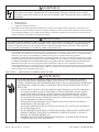
WARNING
Before installing this product, read and follow all warning notices and instructions accompanying this filter. Failure to
follow safety warnings and instructions can result in severe injury, death, or property damage.
Call (800) 831-7133 for additional free copies of this manual.
Important Notice
Attention Installer.
This manual contains important information about the installation, operation and safe use of this product.
This information should be given to the owner/operator of this equipment.
SECTION I.
FILTER INSTALLATION.
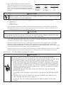
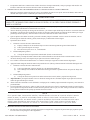
1. The filter should be mounted on a level concrete slab. Position the filter so that the instructions, warnings and pressure
gauge are visible to the operator. Also, position the filter so that the piping
connections, control valve and drain port are convenient and accessible for
servicing and winterizing.
2. Install electrical controls (e.g., on/off switches, timers, control systems,
etc.) at least five (5) feet from the filter. This will allow you enough room to
stand clear of the filter during system start up.
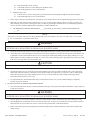
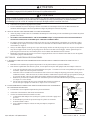
3. Provide sufficient clearance around the filter to permit visual verification
that the clamp is properly installed, see Figure 1.
4. Provide sufficient space above the filter to remove the filter lid or control
valve for cleaning and servicing. This distance will vary with the model of
filter you are using. See Table 1 for the required vertical clearance.
Figure 1.
Pentair Pool Products
1620 Hawkins Ave., Sanford, NC 27330 • (919) 774-4151
10951 West Los Angeles Ave., Moorpark, CA 93021 • (805) 523-2400
Rev. H • Rev. H • Rév. H
12-9-99
1
P/N • Núm/Pte. • Réf. P/N 99226000
5. When installing the High Flow™ manual air relief valve
position the filter to safely direct water drainage. Rotate the
High Flow™ manual air relief valve to safely direct purged air
or water. Water discharged from an improperly positioned
filter or valve can create an electrical hazard as well as damage
to property.
Model
58920100
58920200
58920300
Table 1.
Size
3.5 sq. ft.
4.6 sq. ft.
6.5 sq. ft.
Vert. Clear. Req.
49 in.
51 in.
57 in.
WARNING
Risk of electrical shock or electrocution. Position the filter and High Flow™ manual air relief valve to safely direct water
drainage and purged air or water. Water discharged from an improperly positioned filter or valve can create an electrical hazard
that can cause severe injury as well as damage property.
6. Your filter requires one of the following Pentair Pool Products accessories which must be purchased separately.
a.
b.
c.
Push-pull valve.
Multiport valve.
Bulkhead union set.
7. Make all plumbing connections in accordance with local plumbing and building codes. Filter plumbing connections are
provided with an O-ring seal. Use only a silicone base lubricant on the O-rings. Do not use pipe joint compound, glue or
solvent on the bulkhead connections to avoid damage to the O-rings.
CAUTION
For Multiport control valves with threaded ports use only Teflon tape, 100% pure Teflon paste (non-petroleum base), Permatex #2 sealant
on all threaded pipe connections, except fittings with O-rings. Use of other pipe joint compounds can damage components of this system
and cause leaks. For control valves with slip ports, use only ABS to PVC solvent welding adhesive.
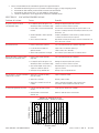
8. The maximum working pressure of this filter is 50 psi, see Table 2. Never subject this filter to pressure in excess of this amount
- even when conducting hydrostatic pressure tests. Pressures above maximum working pressure can cause the lid to be blown
off, which can result in severe injury, death or property damage.
When performing hydrostatic pressure tests or when testing for external leaks of the completed filtration and plumbing
system, insure that the Maximum Pressure that the filtration system will be subjected to DOES NOT EXCEED THE
MAXIMUM WORKING PRESSURE OF ANY OF THE COMPONENTS CONTAINED WITHIN THE SYSTEM. In most
cases, the maximum pressure will be stated on each component of the system.
If doubt exists as to the pressure to which the system will be subjected, install an ASME approved automatic Pressure Relief
or Pressure Regulator in the circulation system for the lowest working pressure of any of the components in the system.
SECTION II.
FILTER OPERATION AND CLEANING.
WARNING
THIS FILTER OPERATES UNDER HIGH PRESSURE. WHEN ANY PART OF THE CIRCULATING SYSTEM (E.G., CLAMP,
PUMP, FILTER, VALVES, ETC.) IS SERVICED, AIR CAN ENTER THE SYSTEM AND BECOME PRESSURIZED.
PRESSURIZED AIR CAN CAUSE THE LID OR CONTROL VALVE TO BLOW OFF WHICH CAN RESULT IN SEVERE INJURY,
DEATH, OR PROPERTY DAMAGE. TO AVOID THIS POTENTIAL HAZARD, FOLLOW THESE INSTRUCTIONS.
1.
BEFORE REPOSITIONING VALVES AND BEFORE BEGINNING THE ASSEMBLY, DISASSEMBLY, OR ADJUSTMENT
OF THE CLAMP OR ANY OTHER SERVICE OF THE CIRCULATING SYSTEM: (A) TURN THE PUMP OFF AND SHUT
OFF ANY AUTOMATIC CONTROLS TO ENSURE THE SYSTEM IS NOT INADVERTENTLY STARTED DURING THE
SERVICING; (B) OPEN HIGH FLOW™ MANUAL AIR RELIEF VALVE; (C) WAIT UNTIL ALL PRESSURE IS RELIEVED,
PRESSURE GAUGE MUST READ ZERO (0).
2.
WHENEVER INSTALLING THE FILTER CLAMP, FOLLOW THE FILTER LID AND CLAMP INSTALLATION
INSTRUCTIONS EXACTLY.
3.
ONCE SERVICE ON THE CIRCULATING SYSTEM IS COMPLETE, FOLLOW SYSTEM RESTART INSTRUCTIONS
EXACTLY.
4.
MAINTAIN CIRCULATION SYSTEM PROPERLY. REPLACE WORN OR DAMAGED PARTS IMMEDIATELY (E.G.,
CLAMP, PRESSURE GAUGE, RELIEF VALVE, O-RINGS, ETC.).
5.
BE SURE THAT THE FILTER IS PROPERLY MOUNTED AND POSITIONED ACCORDING TO INSTRUCTIONS
PROVIDED.
P/N • Núm/Pte. • Réf. P/N 99226000
2
Rev. H • Rev. H • Rév. H
12-9-99
A. GENERAL INFORMATION - HOW YOUR FILTER WORKS.
1.
Your high rate sand filter is designed to produce clear, sparkling water and operate for years with a minimum of maintenance
when installed, operated and maintained in accordance with these instructions:
Your filter uses special filter sand to remove dirt particles from the water. Dirt is collected in the filter by the sand bed as
water flows through the filter. Water enters the filter through the valve on top of the filter (or the top bulkhead fitting in the
case of side mounted control valves). It is then distributed evenly downward, across and through the sand bed. The dirt is
removed by the sand and the clean water flows through the piping (laterals) at the bottom of the filter up through the center
pipe back to the valve on top of the filter (or out of the lower bulkhead on side mounted filters), where the clean water is
returned to the pool through the piping.
After a period of time, dirt will accumulate in the filter causing a resistance to the flow of water through the filter. This
resistance results in a diminished flow rate and a rise in the pressure of the filter. Eventually the filter sand will have removed
so much dirt and the filter pressure risen to such a point that it will be necessary to clean (backwash) your filter.
By setting the control valve on the top or side of the filter to the backwash position, the flow direction of water is reversed
through the filter so that the water is directed to the bottom of the filter and up through the sand bed flushing the dirt and
debris out through the waste line. Once the backwash procedure is complete, the valve must be returned to its filter position to
resume normal filtration.
The filter’s function is to remove suspended matter from the water and does not sanitize the water. For sparkling clear water
the water must be sanitized as well as chemically balanced. Pool chemistry is a specialized area and you should consult your
local pool service specialist for specific details. In general, proper pool sanitation requires a free chlorine level of 1 to 2 PPM
and a pH range of 7.2 to 7.6.
WARNING
Failure to operate your filter system or inadequate filtration can cause poor water clarity obstructing visibility in your pool. POOR WATER
CLARITY MAY OBSCURE OBJECTS IN THE WATER WHICH MAY EXPOSE SWIMMERS OR DIVERS TO THE RISK OF SEVERE INJURY OR
DEATH. NEVER SWIM IN A POOL WITH POOR WATER CLARITY.
2.
This filter operates under pressure. When clamped properly and operated without air in the water system, this filter will
operate in a safe manner.
3.
The pressure gauge is the primary indicator of how the filter is operating. Maintain your pressure gauge in good working order.
CAUTION
The following information should be read carefully since it outlines the proper manner of care and operation for your filter system. As a
result of following these instructions and taking the necessary preventative care, you can expect maximum efficiency and life from your
filtration system.
B. FILTER MEDIA.
1.
Media - Your sand filter uses a #20 grade silica filter sand for its media (.45 - .55 mm). It should be free of all limestone or clay.
Most pool supply and building material stores carry silica sand. See Table 2 for the appropriate amounts of silica sand.
Table 2.
Product #
Filter Diameter
Filter Area
Sand Qty.
Maximum
Working PSI
58920100
58920200
26 in.
30 in.
3.5 sq. ft.
4.6 sq. ft.
225 lbs.
350 lbs.
50 psi
50 psi
58920300
36 in.
6.5 sq. ft.
575 lbs.
50 psi
2.
Remove the lid from your filter and install the sand funnel on the top of the filter tank. It is important to swing the diffuser
basket(s) to a horizontal position before installing the funnel. Fill the tank about half full of water. Pour the silica sand into the
top of the filter tank slowly, so that the weight does not damage the lateral assembly in the bottom of the tank or the overdrain
plumbing near the top of the tank.
3.
After filling the filter tank with the appropriate amount of silica sand, remove the sand funnel and wash away any loose sand
from the opening of the filter tank. Straighten the diffuser basket(s) up into the vertical operating position if you previously
moved them down.
4.
To install lid, follow procedures in Section C, Lid and Valve Installation Instructions.
Rev. H • Rev. H • Rév. H
12-9-99
3
P/N • Núm/Pte. • Réf. P/N 99226000
CAUTION
For Multiport control valves with threaded ports use only Teflon tape, 100% pure Teflon paste (non-petroleum base), or Permatex #2
sealant on all threaded pipe connections, except fittings with O-rings. Use of other pipe joint compounds can damage components of this
system and cause leaks. For control valves with slip ports, use only ABS to PVC solvent welding adhesive.
5.
The maximum working pressure of this filter is 35 or 50 psi, see Table 2. Never subject this filter to pressure in excess of this
amount - even when conducting hydrostatic pressure tests. Pressures above maximum working pressure can cause the lid to be
blown off, which can result in severe injury, death or property damage.
When performing hydrostatic pressure tests or when testing for external leaks of the completed filtration and plumbing
system, insure that the Maximum Pressure that the filtration system will be subjected to DOES NOT EXCEED THE
MAXIMUM WORKING PRESSURE OF ANY OF THE COMPONENTS CONTAINED WITHIN THE SYSTEM. In most
cases, the maximum pressure will be stated on each component of the system.
If doubt exists as to the pressure to which the system will be subjected, install an ASME approved automatic Pressure Relief
or Pressure Regulator in the circulation system for the lowest working pressure of any of the components in the system.
C. LID INSTALLATION INSTRUCTIONS.
These instructions MUST BE FOLLOWED EXACTLY to prevent the lid or valve from blowing off during system restart
or later operation:
1.
Before working on any part of the circulating system, (e.g. clamp, pump, filter, valves, etc.) perform the following steps:
a.
Turn the pump off and shut off any automatic controls to ensure that the system is not inadvertently started during
servicing.
b.
Open the High Flow™ manual air relief valve.
c.
Wait until all pressure is relieved. Never attempt to assemble, disassemble or adjust the lid while there is any
pressure in the filter.
2. Be sure that the chamfered sealing surface inside of the brass, or plastic flange at the top of the tank is clean and free of any
sand or debris. Apply a light coating of SILICONE BASE LUBRICANT to the lid O-ring and install into the opening in the
top of the filter tank.
NOTE
30 in. FILTERS ARE SHIPPED from the factory ready to accept a 2 in. control valve. If you wish to use the 1.5 in. control
valve, it is necessary to remove the 2 in. X 2 in. extension from the stand pipe and replace it with the 2 in. X 1.5 in. extens ion
fitting. This fitting is included in the accessory kit.
3.
Install the lid in the following manner:
a.
4.
Thread the plastic lid into the top tank opening until the O-ring makes contact, then tighten an additional 1/4 to 1/2 turn.
Follow the system restart instructions in Section D.
WARNING
THIS FILTER OPERATES UNDER HIGH PRESSURE. WHEN ANY PART OF THE CIRCULATING SYSTEM (e.g., CLAMP, PUMP,
FILTER, VALVES, ETC.) IS SERVICED, AIR CAN ENTER THE SYSTEM AND BECOME PRESSURIZED. PRESSURIZED AIR CAN
CAUSE THE LID OR VALVE TO BE BLOWN OFF WHICH CAN RESULT IN SEVERE INJURY, DEATH, OR PROPERTY DAMAGE.
TO AVOID THIS POTENTIAL HAZARD, FOLLOW THESE INSTRUCTIONS.
D. SYSTEM RESTART INSTRUCTIONS.
1.
Open the High Flow™ manual air relief valve until it snaps into the full open position (this only requires a quarter turn
counterclockwise). Opening this valve rapidly releases air trapped in the filter.
2.
Stand clear of the filter tank, then start the pump.
3.
Close the High Flow™ manual air relief valve after a steady stream of water appears.
4.
The system is not working properly if either of the following conditions exist:
a.
A solid stream of water does not appear within 30 seconds, after the pump’s inlet basket fills with water.
b.
The pressure gauge indicates pressure before water out-flow appears.
P/N • Núm/Pte. • Réf. P/N 99226000
4
Rev. H • Rev. H • Rév. H
12-9-99
If either condition exists, shut off the pump immediately, open valves in the water return line to relieve pressure, and clean
the High Flow™ manual air relief valve, see Section II, Filter Operation and Cleaning.
If the problem persists, call 1-800-831-7133 for assistance.
E. CONTROL VALVE FUNCTIONS.
1.
2.
Side Mounted Push-pull valves have two operating positions, see Table 3.
a.
Filter, T-handle is fully extended to its uppermost position.
b.
Backwash, T-handle is fully compressed to its lowermost position.
Rotary type multiport control valves offer more operating positions and allow more options on how to direct the flow of water
in your pool system.
a.
8-Way Multiport valves provide all of the following functions, see Table 3.
TABLE 3
FILTER
From pump, through valve, downward through filter sand bed, back through laterals and piping to valve return
port, and back to the pool. This position is used for normal filtering and vacuuming to clean the pool water.
BACKWASH
From pump, through valve, down through piping and laterals, up through filter sand bed to valve, and out
waste port. This position is used for cleaning filter by reversing flow.
RINSE
From the pump, through valve, downward through filter sand bed, back through laterals and piping to valve
and out waste port. This position is used for start-up cleaning and resettling filter bed after backwashing.
WASTE
From pump, through valve (bypasses filter) and goes to waste port. This position is for vacuuming directly to
waste, lowering pool level, or draining pool.
CLOSED
NO FLOW IN THIS POSITION - DO NOT USE THIS SETTING WITH PUMP OPERATING.
RECIRCULATE
From pump, through valve, bypasses filter and goes to return port and back to pool. This position is for
circulating water without going through filter.
SERVICE
NO FLOW IN THIS POSITION - DO NOT USE THIS SETTING WITH PUMP OPERATING. It allows the
removal of the handle pin for servicing.
WINTERIZE
For areas that have freezing temperatures during the winter.
F. FILTER START UP - INITIAL SAND BED RINSE.
1.
Valve operations, with pump shut off:
a. Push-pull backwash valve.
(1)
Push handle down with slight twisting motion as far as it will go.
(2)
Lock upper pin in cap.
(3)
Open High Flow™ manual air relief valve on the filter.
(4)
Proceed through steps 2 to 3 which follow.
b. Multiport rotary valve.
(1)
Position valve to “Backwash” setting.
(2)
Open High Flow™ manual air relief valve on the filter.
(3)
Proceed through steps 2 to 3, which follow.
2.
Follow steps in Section D, System Restart. On initial start up the pump must be primed by filling the hair and lint strainer with
water You may have to do this several times.
3.
Your filter is now backwashing accumulated dust or dirt from the new silica sand bed. Backwash for two (2) minutes, or until
water is flowing clear out the backwash line, or appears clear in sight glass, then shut off pump.
G. FILTER START UP - POOL FILTRATION.
1.
Valve operations, with pump shut off:
a.
Push-pull backwash valve.
(1)
Twist to unlock plunger.
Rev. H • Rev. H • Rév. H
12-9-99
5
P/N • Núm/Pte. • Réf. P/N 99226000
(2)
(3)
(4)
b.
Raise the handle as far as it will go.
Turn handle clockwise to lock under pin in underside of cap.
Proceed through steps G.2 to G.3, which follow.
Multiport rotary valve.
(1)
(2)
Position valve to “Filter” setting. This is your normal flow from the pump through the filter back to the pool.
Proceed through steps G.2 to G.3, which follow.
2.
Follow steps in Section D, System Restart. Your filter is now in full operation. Note the original starting pressure on the gauge.
3.
Backwash your filter when pressure reads between 5 to 11 psi over the original starting pressure, see Step G.5. When your
filter builds up pressure from its starting point, then your filter is performing its function. However, this buildup of pressure
will vary because of different bathing loads, temperature, weather conditions, etc.
a.
MY ORIGINAL STARTING PRESSURE IS _____ psi (pounds per square inch). I SHOULD BACKWASH AT
_____ psi
NOTE
Small grains of sand may leave the filter during backwashing or may even appear at the return line when filter is first started
up. This is characteristic of permanent media filters.
WARNING
Always turn pump off before changing valve positions. CHANGING VALVE POSITIONS WHILE THE PUMP IS RUNNING CAN DAMAGE
THE CONTROL VALVE, AND MAY RESULT IN PERSONAL INJURY OR PROPERTY DAMAGE.
4.
Check the system for water leaks. If a leak is found, shut pump off and relieve system pressure, before correcting the leak.
5.
As the filter removes dirt and impurities from the pool water, the accumulation will cause the filter pressure to rise and the flow
to diminish. It is time to backwash the filter if you are using 1hp or smaller pump and the pressure gauge reading is 5 to 7 psi
higher than the clean filter reading noted in Step G.3, above. For systems with larger than 1 hp pumps, this pressure rise will be
in the 9 to 11 psi range before it is time to backwash.
CAUTION
To prevent damage to the pump and filter and for proper operation of the system, clean pump strainer and skimmer baskets regularly.
H. FILTER CLEANING - CLEANING FREQUENCY.
I.
1.
Cleaning frequency will vary from pool to pool and with other factors such as weather conditions, heavy rains, dust pollen,
bather load, and water chemistry. Check the pressure gauge reading on a regular basis. If you have a 1 HP or smaller pump,
backwash when the pressure gauge reading increases 5 to 7 psi over the initial clean filter reading. With larger pumps,
backwash when the increase is 9 to 11 psi.
2.
It is important NOT to backwash the filter solely on a timed basis such as every two days. Backwashing too frequently
actually causes poor filtration.
FILTER CLEANING - FILTER BACKWASH PROCEDURE.
1. Since the sand media bed is the key to efficient filtration in this type filter system, that media bed should be visually inspected
at least once each year.
WARNING
Always turn pump off before changing valve positions. CHANGING VALVE POSITIONS WHILE THE PUMP IS RUNNING CAN DAMAGE
THE CONTROL VALVE, AND MAY RESULT IN PERSONAL INJURY OR PROPERTY DAMAGE.
2. Turn the pump off, shut off any automatic controls to ensure that the system is not inadvertently started during servicing.
3. Open the High Flow™ manual air relief valve and waste drain valve, or plug, if your system has one. Ensure that suction and
backwash lines are open so that water is free to come from the pool and flow out the backwash line.
4. Remove hair and lint pot lid from pump and clean basket. Replace basket, refill hair and lint pot with water, install lid and
clamp securely.
P/N • Núm/Pte. • Réf. P/N 99226000
6
Rev. H • Rev. H • Rév. H
12-9-99
5. Valve Operations:
a.
b.
Push-pull backwash valve.
(1)
Push handle on valve down with slight twisting motion as far as it will go.
(2)
(3)
Lock upper pin in cap.
Proceed through steps I.6 to I.11, which follow.
Multiport rotary valve.
(1)
Position valve to ‘Backwash’ setting.
6. Stand clear of the filter and start pump. Filter is now running in its backwash mode. Close High Flow™ manual air relief valve
only after a continuous stream of water is flowing from the valve.
7. Backwash filter for approximately 3-5 minutes or until backwash water is clean.
8. Turn off pump. Set control valve back to filter position and open High Flow™ manual air relief valve again.
a.
b.
Push-pull backwash valve.
(1)
Twist to unlock plunger; then raise handle as far as it will go.
(2)
Turn handle clockwise to lock upper pin in underside of cap.
Multiport rotary valve.
(1)
Position valve to ‘Filter and Vacuum to Pool’ setting.
9. Stand clear of the filter and start pump. Close High Flow™ manual air relief valve only after a continuous stream of water is
flowing from the valve.
10. The filter has now started its filtering cycle. Check that there is water returning to the pool and take note of the filter pressure.
11. The filter pressure in step I.7 above should not exceed the pressure originally observed on the filter when it was initially
started. If, after backwashing, the pressure is 4 to 6 psi above the start condition, it may be necessary to change the sand in the
filter.
NOTE
Over a period of time certain foreign matter and materials can become imbedded in the top of the sand media bed and will successfully resist
being flushed out during the backwash cycle. During inspection as noted above, this foreign material and any contaminated sand should be
removed from the tank. Replace any old sand removed with new clean silica sand. Replace tank lid or valve and carefully follow instructions
in Section C, Lid and Valve Installation Instructions.
J. WINTERIZING THE FILTER.
1.
In areas that have freezing winter temperatures the pool equipment must be winterized to protect it from damage.
2.
Backwash the filter. Shut off the pump, any automatic controls and set the rotary multiport control valve to the winterize
position. For Push-pull valve equipped filters, leave the valve in the backwash (T-handle down) position.
3.
Remove the small knurled drain port cap at the bottom of the filter.
NOTE
Remove ONLY the drain port cap to drain water from filter.
CAUTION
Removing the entire fitting will drain the sand. The filter will drain slowly. Leave the drain port cap off and store it during the time the
system is shut down.
CAUTION
The rotary multiport control valve should be left in the winterize position during the shutdown season so that the rubber seal of the valve
diverter has no pressure on it. Failure to do so can damage the valve’s spider gasket which can cause property damage from leaking
water.
4.
Drain all appropriate system piping.
5.
It is recommended that the pump and filter be covered with a tarpaulin or plastic sheet to inhibit deterioration from the weather.
DO NOT wrap pump motor with plastic.
Rev. H • Rev. H • Rév. H
12-9-99
7
P/N • Núm/Pte. • Réf. P/N 99226000
K. CLEANING THE HIGH FLOW™ MANUAL AIR RELIEF VALVE.
1.
Turn the pump off and shut off any automatic controls to ensure
that the system is not inadvertently started during servicing.
2.
OPEN THE HIGH FLOW™ MANUAL AIR RELIEF VALVE
UNTIL IT SNAPS INTO THE FULL OPEN POSITION, THEN
WAIT UNTIL ALL PRESSURE IS RELIEVED.
3.
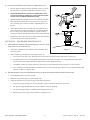
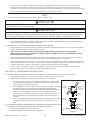
With the High Flow™ manual air relief valve attached to the filter
tank, pull out the locking tabs and remove the valve stem and
cover assembly with a counter-clockwise and lifting motion, see
Figure 2.
4.
Clean debris from the valve stem and body. Verify that the filter
tank’s air passage is open by inserting a 5/16 in. drill bit through
the valve body. Verify that the O-rings are in good condition,
properly positioned, and lubricated with a silicone based lubricant.
5.
Reinstall the valve stem and cover assembly with a downward and
clockwise motion until it snaps into position.
SECTION III. EQUIPMENT MAINTENANCE.
A. AIR ENTERING YOUR FILTER IS DANGEROUS AND CAN CAUSE
THE LID OR VALVE TO BLOW OFF.
1.
Correct any conditions in your filtration system that allow air to
enter the system.
2.
Some common ways to identify air entering the system are:
Figure 2.
a.
Low water level in pool or spa - skimmer is starving for water with pump running. Add water to pool or spa.
b.
Air bubbles or low water level in pump hair and lint pot are caused by: Low water level, clogged skimmer basket, split
suction cleaner hose, leak in pump hair and lint pot lid, or leak in pump suction line.
c.
Air bubbles coming out of water return lines into the pool or spa with pump running, see Steps 2.a. and 2.b. above.
d.
Air is discharged from the High Flow™ manual air relief valve on top of the filter when the valve is opened with the pump
running, see Steps 2.a. and 2.b. above.
B. THE PRESSURE GAUGE IS YOUR PRIMARY INDICATOR OF HOW THE FILTER SYSTEM IS OPERATING.
1.
It is an important part of your filter system.
2.
Maintain your pressure gauge in good working order.
3.
Check the operation of your pressure gauge in the following manner:
a.
The pressure gauge should go to zero (0) when the system is turned off and pressure is relieved.
b.
The pressure gauge should indicate pressure when the system is operating.
c.
The pressure gauge should be readable and not damaged in any way.
d.
Replace the pressure gauge if any of the above conditions exist.
P/N • Núm/Pte. • Réf. P/N 99226000
8
Rev. H • Rev. H • Rév. H
12-9-99
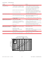
SECTION IV. TROUBLE SHOOTING.
System Problem
Cause
Remedy
Pool water not
1. Pool chemistry not adequate to inhibit algae growth.
Maintain pool chemistry or consult pool service technician.
sufficiently clean.
2. Backwashing too frequently.
Allow pressure to build to 5-11 psi above clean filter condition before
backwashing, see SECTION II, G.5.
3. Improper amount or wrong sand size.
Check sand bed depth and sand size or consult pool service technician.
4. Inadequate turnover rate.
Run system for longer time or consult pool service technician.
1. Insufficient backwashing.
Backwash until water runs clear.
2. Sand bed plugged with mineral deposits.
Chemically clean filter and/or change sand, see SECTION I.
3. Partially closed valve or restriction in return.
Open valve or remove obstruction in return line.
Requires frequent backwash
1. Improper backwash.
Backwash until water runs clear.
(short filter cycle).
2. Pool chemistry not adequate to inhibit algae growth.
Maintain pool chemistry or consult pool service technician.
3. Plugged sand bed.
Manually remove top 1 in. surface of sand bed and chemically clean as
required.
4. Flow rate too high.
Restrict flow to capacity of filter.
High filter pressure.
Return flow to pool diminished 1. Obstruction in pump hair and lint strainer.
Clean basket in strainer.
and low filter pressure.
2. Obstruction in pump.
Disassemble and clean pump.
3. Obstruction in suction line to pump.
Clean skimmer basket. Remove obstruction in lines. Open valves in
suction line.
Sand returning to pool.
Rev. H • Rev. H • Rév. H
1. Broken underdrain lateral.
Replace broken or damaged laterals.
2. Backwash rate too high.
Reduce backwash flow rate.
12-9-99
9
P/N • Núm/Pte. • Réf. P/N 99226000
SECTION V.
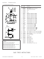
TECHNICAL DATA
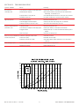
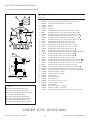
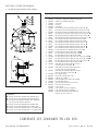
A. ECLIPSE SIDE MOUNT FILTER.
1
2
3
4
5
6
8
7
9
10
12
11
8
7
13
10
Item
No.
Part
No.
1
2
3
4
5
6
7
7
7
7
7
7
8
8
8
8
8
8
9
9
9
9
9
9
9
9
10
10
10
11
11
11
11
12
12
13
53003201
98218900
98209800
57006800
55022000
52000500
55008300
150017
55008900
150018
55009100
150019
55120000
150020
55120100
150021
55120200
150022
51999100
55020300
150023
150037
55020800
150024
150038
150044
55025800
55025900
55026300
55007800
86300300
86300400
86300500
55226100
55235000
53007111
51021500
52000100
52000200
55023200
LEGEND
Ê
Ë
Ì
Í
Î
Ï
Ð
Used on filters manufactured before 9-94.
Used on filters manufactured after 9-94.
New improved laterals will fit hubs previously manufactured.
Used on filters manufactured before 11-98.
Used on filters manufactured after 11-98.
Used on filters manufactured before 11-1-99.
Used on filters manufactured after 11-1-99.
Description
Gauge, pressure
Plug for High Flow manual air relief valve
High Flow manual air relief valve
O-ring
Lid
O-ring
Basket assy., overdrain 26 in. filter Í
Diffuser assy., overdrain 26 in. filter Î
Basket assy., overdrain 30 in. filter Í
Diffuser assy., overdrain 30 in. filter Î
Basket assy., overdrain 36 in. filter Í
Diffuser assy., overdrain 36 in. filter Î
Internal drain pipe assy., 26 in. filter Í
Internal drain pipe assy., 26 in. filter Î
Internal drain pipe assy., 30 in. filter Í
Internal drain pipe assy., 30 in. filter Î
Internal drain pipe assy., 36 in. filter Í
Internal drain pipe assy., 36 in. filter Î
Kit, service air tube, 3/8 in. o.d. Ê
Kit, service air tube, 26 in. filter ËÍ
Kit, service air tube, 26 in. filter ÎÏ
Kit, service air tube, 26 in. filter Ð
Kit, service air tube, 30 & 36 in. filter ËÍ
Kit, service air tube, 30 & 36 in. filter ÎÏ
Kit, service air tube, 30 & 36 in. filter Ð
Kit, service air tube, 36 in. filter Ð
Lateral, underdrain, 26 in. filter, (3-7/8 in.), 8 per filter Ì
Lateral, underdrain, 30 in. filter, (7-7/8 in.), 8 per filter Ì
Lateral, underdrain, 36 in. filter, (10 in.), 8 per filter Ì
Drain assy., complete
Fitting, drain sand/water
Cap, drain
Gasket, drain cap
Base, 26 in. filter
Base, 30 & 36 in. filter
Fitting, bulkhead, outer
Gasket, bulkhead
O-ring, bulkhead, (1) req.
O-ring, bulkhead, (2) req.
Funnel, sand filling, 26, 30 & 36 in. filter
SAVE THESE INSTRUCTIONS.
P/N • Núm/Pte. • Réf. P/N 99226000
10
Rev. H • Rev. H • Rév. H
12-9-99
Eclipse™ High Rate Sand Filter
Pentair Pool Products Limited Warranty
PENTAIR POOL PRODUCTS manufactures its "Eclipse" high rate
sand filter under high standards of workmanship and with high quality
materials. Accordingly, Pentair Pool Products expressly warrants
those filter models as follows:
8. External damage to chamber, bulkhead areas or bottom threads that
occur through improper plumbing or damage during installation.
WARRANTY OBLIGATIONS OF PENTAIR POOL PRODUCTS–
Should a defect in workmanship and/or material in any item covered
by this warranty become evident during the term of the warranty, then
upon the consumer following the procedures set forth below, Pentair
Pool Products will, at its option, repair or replace such item or part at
its own cost and expense. Pentair Pool Products is not, however,
responsible under this warranty for any cost of shipping or
transportation of the filter or part thereof to or from the service
department. Also, Pentair Pool Products is not liable for any loss of
time, inconvenience, incidental expenses such as telephone calls, labor
or material charges incurred in connection with the removal or
replacement of the equipment, or any other incidental or consequential
damages.
WARRANTY COVERAGE–All molded, internal components of
Pentair Pool Products Eclipse filters, which are actually manufactured
by Pentair Pool Products are warranted to be free from defects in
material and/or workmanship for a period of three (3) years from date
of purchase. In addition, the tanks of such filters are warranted to be
free from defects in material and/or workmanship for a period of ten
(10) years from date of purchase. The Multiport Valve used on the
Eclipse filter has a one (1) year warranty. The obligation of Pentair
Pool Products under this warranty will be limited to either repair or
replacement of the filter tank, at Pentair Pool Products option. If
Pentair Pool Products elects to replace the filter tank or part thereof,
the owner agrees to pay Pentair Pool Products a charge based upon the
time which has elapsed since the filter was purchased according to the
schedule below. The percentage factor will be applied to current
published list price of the filter tank at the time the warranty claim
occurs. The amount of the charge will be determined as follows:
Elapsed Time
Since Purchase
1 to 5 years
5 to 6 years
6 to 7 years
7 to 8 years
8 to 9 yeas
9 to 10 years
PLEASE NOTE–Some states do not allow the exclusion or limitation
of incidental or consequential damages, so the above limitation or
exclusion may not apply to you.
PROCEDURE FOR OBTAINING WARRANTY PERFORMANCE–
In order to obtain the benefits of this warranty, the consumer who
made the original retail purchase shall contact Pentair Pool Products',
Service Department, 10951 West Los Angeles Ave., Moorpark, CA
93021, as soon as possible after discovery of the defect, but in no
event later than the expiration date of the warranty period provided in
this warranty. Upon receipt of this communication, Pentair Pool
Products will promptly notify the customer of the address to which
the defective item may be shipped. The customer shall then ship the
item, freight prepaid, to the address indicated together with a letter
stating the model number, serial number, copy of sales receipt showing
date of purchase of the item which is claimed to be defective, and the
name and address of the consumer. Also, include a brief description of
the problems encountered.
% of Published
List Price
Paid by Owner
0%
50%
60%
70%
80%
90%
EXCLUSIONS FROM THIS WARRANTY–
This warranty does not cover:
1. Any item manufactured by other companies and installed by Pentair
Pool Products (such as air or water valves, gauges, plumbing
fittings, pipes, bolts, nuts, clamps, etc.).
WARRANTY PROTECTS ORIGINAL RETAIL PURCHASER–
This warranty extends to the consumer who made the original retail
purchase only and is not enforceable by any other party.
2. Problems resulting from oversizing of pump and/or reduction of
valve piping size, or from failure to turn pump off before changing
the position of the filter valve or any operating valves for the pool
and its accessories.
WARRANTIES OR REPRESENTATIONS BY OTHERS–No dealer
or other person has any authority to make any warranties or
representations concerning Pentair Pool Products or its products.
Accordingly, Pentair Pool Products is not responsible for any such
warranties or representations.
3. Problems resulting from failure to comply with instructions
contained in the Owner's Manual.
4. Problems resulting from abuse, misuse, negligence or accident by
any party other than Pentair Pool Products.
OTHER RIGHTS–This warranty gives you specific legal rights, and
you may also have other rights which vary from state to state.
5. Problems resulting from exposure to temperatures below freezing or
in excess of 125 degrees Fahrenheit.
6. Problems resulting in whole or in part from alteration or
modification of the filter by any party.
7. Failures due to chemical corrosion, caused by failure to maintain the
pool water chemistry in conformity with the standards of the
swimming pool industry.
Pentair Pool Products
1620 Hawkins Ave., Sanford, NC 27330 • (919) 774-4151
10951 West Los Angeles Ave., Moorpark, CA 93021 • (805) 523-2400
Rev. H • Rev. H • Rév. H
12-9-99
11
P/N • Núm/Pte. • Réf. P/N 99226000
Manual del Propietario del Filtro de Arena
de Gran Rendimiento Eclipse™
INSTRUCTIVOS IMPORTANTES DE SEGURIDAD
LEA Y SIGA TODOS LOS INSTRUCTIVOS
PROTEJA ESTOS INSTRUCTIVOS
Indice
SECCIÓN I.
INSTALACIÓN DEL FILTR. ............................................................................................................ 13
SECCIÓN II.
OPERACIÓN Y LIMPIEZA DEL FILTRO ....................................................................................... 14
SECCIÓN III. MANTENIMIENTO DEL EQUIPO .................................................................................................. 20
SECCIÓN IV. LOCALIZACIÓN DE FALLAS ........................................................................................................ 21
SECCIÓN V.
INFORMACIÓN TÉCNICA ............................................................................................................... 22
ADVERTENCIA
Antes de instalar este filtro de arena de gran rendimiento Eclipse de Pentair Pool Products, lea y siga todos los avisos de
advertencia y los instructivos que acompañan al filtro. El no apegarse a los avisos de seguridad y a los instructivos podría
dar por resultado una lesión grave, la muerte o daños a la propiedad. Comuníquese con su proveedor local para obtener
ejemplares gratuitos o llame a Pentair Pool Products al (805) 523-2400 .
Aviso Importante
A la atención del instalador(a):
Este manual contiene información importante sobre la instalación, operación y uso en forma segura de este
producto. Esta información debe dársele al dueño(a) / operador(a) de este equipo.
1.
2.
INSTALACIÓN DEL FILTRO.
El filtro debe montarse sobre una losa nivelada de hormigón armado
(concreto). Coloque el filtro de tal manera que los instructivos, las
advertencias y el medidor de presión (manómetro) queden visibles al
operador. También coloque el filtro de tal manera que las conexiones de las
tuberías, la válvula de control y la abertura del drenaje (desagüe) queden en
una forma conveniente y accesible para darle servicio y prepararlo para el
invierno.
Instale los controles eléctricos (por ejemplo, los interruptores de encendido/
apagado, contadores de tiempo, sistemas de control, etc.) por lo menos a 1.5
metros de distancia del filtro. Esto le permite alejarse del filtro durante el
arranque del sistema.
PARED O ESTRUCTURA
PARED O ESTRUCTURA
SECCIÓN I.
FILTRO
ESPACIO MÍNIMO
DE 15 cm
ESPACIO MÍNIMO DE 15 cm
Figura 1.
Figure 1
3.
Deje suficiente espacio alrededor del filtro para poder verificar visualmente
que la abrazadera está instalada en la forma correcta, vea la figura 1.
4.
Deje suficiente espacio por encima del filtro para poder sacar la tapa del filtro con el fin de limpiarla y darle servicio. Esta
distancia variará de acuerdo con el modelo del filtro que esté usando. Vea la tabla 1 donde aparecen los claros verticales que
se requieren.
5.
Al instalar la válvula de gran flujo de descarga de
aire, coloque el filtro de tal manera que éste dirija el
drenaje del agua en forma segura. Gire la válvula de
gran flujo de descarga de aire de tal manera que ésta
dirija en forma segura el aire o el agua purgados. El
agua que se descarga de un filtro o válvula
colocado(a) en forma incorrecta puede crear un
riesgo eléctrico y también daños a la propiedad.
P/N • Núm/Pte. • Réf. P/N 99226000
TABLA 1
Modelo
Tamaño
Claro vertical requerido
58920100 3.5 pies2 (0.325 m²)
49 pulg. (1.24 m)
2
58920200 4.6 pies (0.427 m²)
51 pulg. (1.30 m)
2
58920300 6.5 pies (0.604 m²)
57 pulg. (1.45 m)
12
Rev. H • Rev. H • Rév. H
12-9-99
ADVERTENCIA
Riesgo de choque eléctrico o electrocución. Coloque el filtro y la válvula de gran flujo de descarga de aire de tal forma que
éstos dirijan en forma segura el drenaje del agua y el aire o agua purgados. El agua que se descarga de un filtro o válvula
colocado(a) en forma incorrecta puede crear un riesgo eléctrico que podría causar lesiones personales graves y también daños
a la propiedad.
6.
Su filtro requiere de uno de los siguientes accesorios de Pentair Pool Products, el cual tiene que comprarse por separado.
a. Válvula de vaivén.
b. Válvula multipuerto.
c. Conjunto de unión para los filtros.
7.
Haga todas las conexiones de plomería (fontanería) de acuerdo con los códigos locales de plomería y construcción. Las
conexiones de la plomería están provistas de un empaque redondo para sellar. Use únicamente lubricantes a base de silicona
en los empaques redondos. No use compuestos para uniones de plomería, pegamentos o solventes en las conexiones de las
uniones con el fin de evitar daños a los empaques redondos.
PRECAUCIÓN
Para las válvulas de control multipuerto con puertos (entradas) roscadas, use únicamente cinta de teflón, pasta 100 % de teflón (no a base
de petróleo), o sellador Permatex #2 en todas las conexiones de tubos roscados, excepto en los acopladores con empaques redondos. Si
se usan otros compuestos para unir los tubos se podrían dañar los componentes de este sistema y causar fugas. Para las válvulas de
control con puertos de deslizamiento, use sólo adhesivo soldador solvente de ABS a PVC.
8.
La presión máxima de funcionamiento de este filtro es de 50 psi (344.7 kPa). Nunca someta el filtro a presiones que excedan
esta cantidad - aun cuando lleve a cabo pruebas de presión hidrostática. Las presiones superiores a los 3.52 kg/cm2 pueden
causar que vuele la tapa, lo que podría dar por resultado lesiones graves, la muerte o daños a la propiedad.
Cuando lleve a cabo pruebas de presión hidrostática o cuando haga pruebas con el fin de encontrar fugas exteriores en el sistema
terminado de filtración y plomería, asegúrese de que la presión máxima a la que se someterá el sistema de filtrado NO EXCEDA
LA PRESIÓN MÁXIMA DE FUNCIONAMIENTO DE CUALQUIERA DE LOS COMPONENTES QUE INTEGRAN EL
SISTEMA. En la mayoría de los casos, la presión máxima está indicada en cada uno de los componentes del sistema.
Si hay alguna duda respecto a la presión a la que se someterá el sistema, instale una válvula de descarga de presión automática
o un regulador de presión que estén aprobados por ASME en el sistema de circulación para la presión de funcionamiento más
baja de cualquiera de los componentes del sistema.
SECCIÓN II.
OPERACIÓN Y LIMPIEZA DEL FILTRO.
ADVERTENCIA
ESTE FILTRO FUNCIONA A ALTA PRESIÓN. CUANDO SE LE DA SERVICIO A ALGUNA PIEZA DEL SISTEMA DE
CIRCULACIÓN (POR EJEMPLO: ABRAZADERA, BOMBA, FILTRO, VÁLVULAS, ETC.), PUEDE ENTRARLE AIRE AL
SISTEMA Y PRESURIZARSE. EL AIRE PRESURIZADO PUEDE VOLAR LA TAPA, LO QUE PODRÍA DAR POR RESULTADO
UNA LESIÓN GRAVE, LA MUERTE O DAÑOS A LA PROPIEDAD. PARA EVITAR ESTE POSIBLE RIESGO, SIGA ESTOS
INSTRUCTIVOS.
1.
2.
3.
4.
5.
ANTES DE MOVER LAS VÁLVULAS Y ANTES DE COMENZAR EL ARMADO, DESARMADO O AJUSTE DE LA ABRAZADERA O
DE CUALQUIER OTRO SERVICIO QUE SE LE ESTÉ HACIENDO AL SISTEMA DE CIRCULACIÓN: (A) APAGUE LA BOMBA Y
APAGUE O CIERRE TODOS LOS CONTROLES AUTOMÁTICOS QUE HAYA PARA ASEGURARSE DE QUE EL SISTEMA NO
ARRANCARÁ POR SÍ MISMO EN FORMA INADVERTIDA DURANTE LA REALIZACIÓN DE ESTE SERVICIO. (B) ABRA LA
VÁLVULA DE DESCARGA DEL AIRE; (C) ESPÉRESE HASTA QUE TODA LA PRESIÓN SE HAYA DESCARGADO Ð EL MEDIDOR
DE LA PRESIÓN (MANÓMETRO) DEBE ESTAR EN CERO (0).
SIEMPRE QUE INSTALE UNA ABRAZADERA DE FILTRO, APÉGUESE A LAS INSTRUCTIVOS DE INSTALACIÓN DE LA
ABRAZADERA DE FILTRO EN UNA FORMA EXACTA.
UNA VEZ QUE SE TERMINE DE DAR SERVICIO AL SISTEMA DE CIRCULACIÓN, SIGA LAS INSTRUCTIVOS DE ARRANQUE
DEL SISTEMA EN FORMA EXACTA.
DÉLE EL MANTENIMIENTO ADECUADO AL SISTEMA DE CIRCULACIÓN. CAMBIE LAS PIEZAS DESGASTADAS O
DAÑADAS DE INMEDIATO (POR EJEMPLO: LA ABRAZADERA, EL MEDIDOR DE PRESIÓN, LA VÁLVULA DE
DESCARGA, LOS EMPAQUES REDONDOS, ETC.)
ASEGÚRESE DE QUE EL FILTRO ESTÁ MONTADO ADECUADAMENTE Y COLOCADO EN UNA POSICIÓN QUE
CONCUERDE CON LOS INSTRUCTIVOS PROVISTOS.
Rev. H • Rev. H • Rév. H
12-9-99
13
P/N • Núm/Pte. • Réf. P/N 99226000
A. INFORMACIÓN GENERAL - CÓMO FUNCIONA SU FILTRO.
1.
Su filtro de arena de gran rendimiento está diseñado para producir agua limpia y destellante y para funcionar durante años con
un mínimo de mantenimiento cuando se le instala, opera y mantiene de acuerdo con estos instructivos.
Su filtro usa una arena especial de filtrado para quitar las partículas de mugre que haya en el agua. La mugre se recolecta en el
filtro junto a la cama de arena con el paso del agua a través del filtro. El agua entra en el filtro a través de la válvula en la
parte superior del filtro (o a través de los accesorios de unión superiores en el caso de las válvulas de control montadas a los
lados) . Entonces, se distribuye en forma pareja hacia abajo a través de la cama de arena. La mugre es removida por la arena y
el agua limpia fluye a través de la tubería (partes laterales) que hay en el fondo del filtro, y sube a través de la tubería central,
de vuelva a la válvula en la parte superior del filtro (o hacia afuera por las uniones inferiores en los filtros montados a los
lados), desde donde el agua limpia regresa a la piscina a través de la tubería.
Después de un plazo de tiempo, la mugre se acumulará en el filtro causando cierta resistencia al flujo de agua a través del
filtro. Esta resistencia resulta en un flujo de agua reducido y en un aumento en la presión del filtro. Finalmente, la arena de
filtrado habrá quitado tanta mugre y la presión del filtro habrá subido a tal grado que será necesario limpiar (a
contracorriente) su filtro.
Con sólo poner la válvula de arriba de su filtro en la posición de lavado a contracorriente (backwash), el flujo del agua se
invertirá automáticamente a través del filtro de manera que dicho flujo de agua se dirija hacia el fondo del filtro, suba a través
de la cama de arena, deslavando a presión la mugre y los desechos a través de la tubería de desperdicio. Una vez que se
termine el procedimiento de lavado a contracorriente, la válvula se tiene que regresar a su posición de filtrado para proseguir
con el filtrado normal.
La función del filtro es la de remover las materias suspendidas en el agua y no depura o higieniza el agua. Para obtener agua
clara y destellante ésta se tiene que depurar y también balancear químicamente. La composición química del agua de las
piscinas es una área especializada, y usted debe consultar al especialista en servicios a piscinas de su localidad para obtener
los detalles específicos. En general, la depuración adecuada de las piscinas requiere un nivel de cloro libre de 1 a 2 partes por
millón y una gama de 7.2 a 7.6 en el factor pH.
ADVERTENCIA
El no operar su sistema de filtrado en la forma adecuada, o un filtrado incorrecto, puede causar una claridad deficiente del agua en su
piscina. LA CLARIDAD DEFICIENTE PODRÍA OBSCURECER OBJETOS EN EL AGUA Y EXPONER A LOS NADADORES O CLAVADISTAS A
UN RIESGO DE QUEDAR LESIONADOS GRAVEMENTE O DE MUERTE. NUNCA NADE EN UNA PISCINA QUE TENGA UNA CLARIDAD
DEFICIENTE DEL AGUA.
2.
Este filtro funciona bajo presión. Cuando se le sujeta correctamente con la abrazadera y se le hace funcionar sin aire en el
sistema de agua, este filtro funcionará en una forma segura.
3.
El medidor de presión (manómetro) es el indicador principal de la forma en que está funcionando el filtro. Mantenga el
medidor de presión en buenas condiciones.
PRECAUCIÓN
La siguiente información debe leerse cuidadosamente pues en ella se esboza la forma adecuada de cuidado y de funcionamiento de su
sistema de filtrado. Usted puede esperar una eficiencia y rendimiento máximos de su sistema de filtrado si se apega a estos instructivos y
toma los cuidados preventivos necesarios.
B. MATERIAL DEL FILTRO
1.
Su filtro de arena de gran rendimiento usa arena para filtro hecha de sílice de grado #20 como material (.45 a .55 mm). Debe
estar libre de piedra caliza y de barro. La mayoría de las tiendas de suministros y materiales para la construcción venden arena
de sílice (silica sand). Consulte la tabla 2 para determinar las cantidades adecuadas de arena de sílice.
Núm. del Producto
58920100
58920200
58920300
Válvula
Lateral
Lateral
Lateral
TABLA 2
Área del filtro
3.5 pies2 (0.325 m2)
4.6 pies2 (0.427 m2)
6.5 pies2 (0.604 m2)
Cantidad de arena
225 lbs (102 kg)
350 lbs (159 kg)
575 lbs (261 kg)
Maxima Operacíon
50 psi
50 psi
50 psi
2.
Quite la tapa del filtro e instale el embudo de arena en la parte superior del tanque del filtro. Para los filtros con válvulas
montadas en los lados es importante girar la(s) canastilla(s) del difusor a una posición horizontal antes de instalar el embudo.
Llene el tanque con agua, más o menos hasta la mitad. Vierta lentamente la arena de sílice por la parte superior del tanque del
filtro, de tal manera que el peso no dañe el conjunto lateral en el fondo del tanque o la tubería de sobredrenaje que está cerca
de la parte superior del tanque.
3.
después de llenar el tanque del filtro con la cantidad adecuada de arena de sílice quite el embudo de arena y, lavando, limpie
cualquier arena suelta que haya quedado en la abertura del tanque del filtro. Enderece la(s) canastilla(s) del difusor hacia
arriba a su posición vertical de funcionamiento si es que antes las había movido hacia abajo.
P/N • Núm/Pte. • Réf. P/N 99226000
14
Rev. H • Rev. H • Rév. H
12-9-99
4.
Para completar la instalación de la tapa, siga las instrucciones en la sección C, Instrucciones para la instalación de la tapa y de
la válvula.
PRECAUCIÓN
Para las válvulas de control multipuerto con puertos (entradas) roscadas, use únicamente cinta de teflón, pasta 100 % de teflón (no a base
de petróleo), o sellador Permatex #2 en todas las conexiones de tubos roscados, excepto en los acopladores con empaques redondos. Si
se usan otros compuestos para unir los tubos se podrían dañar los componentes de este sistema y causar fugas. Para las válvulas de
control con puertos de deslizamiento, use sólo adhesivo soldador solvente de ABS a PVC.
5.
La presión máxima de funcionamiento de este filtro es de 50 psi (344.7 kPa). Nunca someta el filtro a presiones que excedan
esta cantidad — aun cuando lleve a cabo pruebas de presión hidrostática. Las presiones superiores a los 50 psi pueden causar
que vuele la tapa, lo que podría dar por resultado lesiones graves, la muerte o daños a la propiedad.
Cuando lleve a cabo pruebas de presión hidrostática o cuando haga pruebas con el fin de encontrar fugas exteriores en el
sistema terminado de filtración y plomería, asegúrese de que la presión máxima a la que se someterá el sistema de filtrado NO
EXCEDA LA PRESIÓN MÁXIMA DE FUNCIONAMIENTO DE CUALQUIERA DE LOS COMPONENTES QUE
INTEGRAN EL SISTEMA. En la mayoría de los casos, la presión máxima está indicada en cada uno de los componentes del
sistema.
Si hay alguna duda respecto a la presión a la que se someterá el sistema, instale una válvula de descarga de presión
automática o un regulador de presión que estén aprobados por ASME en el sistema de circulación para la presión de
funcionamiento más baja de cualquiera de los componentes del sistema.
C. INSTRUCCIONES PARA LA INSTALACIÓN DE LA TAPA.
Estos instructivos TIENEN QUE SEGUIRSE EXACTAMENTE para evitar que la tapa vuele al volver a arrancar el sistema o durante
su funcionamiento posterior:
1.
2.
Antes de trabajar en cualquier parte de su sistema de circulación (por ejemplo, abrazadera, bomba, filtro, válvulas, etc.) lleve
a cabo los siguientes pasos.
a.
Apague la bomba y cierre o apague todos los controles automáticos que haya para asegurarse de que el sistema no
arrancará por sí mismo en forma inadvertida durante la realización de este servicio.
b.
Abra la válvula de descarga de aire.
c.
Espere a que se desahogue toda la presión. Nunca trate de tapadera ensanblar o ajustar la abrazadera del filtro
mientras haya presión en el filtro.
Cerciórese de que la superficie biselada de sellado dentro del latón, o el reborde de plástico en la parte superior del tanque
estén limpios y que no tengan arena ni residuos. Aplique una mano ligera de LUBRICANTE A BASE DE SILICONA al
empaque redondo de la tapa e instálelo dentro de la abertura en la parte superior del tanque del filtro.
NOTA
LOS FILTROS DE 76 cm (30”) SE ENVÍAN desde la fábrica listos para aceptar una válvula de control de 5 cm (2”). Si
quiere usar la válvula de control de 3.81 cm (1.5”), necesitará quitar la extensión de 5 x 5 cm (2” x 2”) del tubo de soporte
y cambiarla por un acoplador de extensión de 5 x 3.81 cm (2 x 1.5”). Este adaptador se incluye junto con el conjunto de
accesorios.
3.
Instale la tapa de la siguiente manera:
a.
4.
Simplemente enrosque la tapa de plástico dentro de la abertura superior del tanque hasta que el empaque redondo haga
contacto, entonces apriételo dándole entre 1/4 y 1/2 vuelta más.
Siga las instrucciones para volver a arrancar el sistema en la sección D.
ADVERTENCIA
ESTE FILTRO FUNCIONA A ALTA PRESIÓN. CUANDO SE LE DA SERVICIO A ALGUNA PARTE DEL SISTEMA DE
CIRCULACIÓN (POR EJEMPLO: ABRAZADERA, BOMBA, FILTRO, VÁLVULAS, ETC.), PUEDE ENTRARLE AIRE AL
SISTEMA Y PRESURIZARSE. EL AIRE PRESURIZADO PUEDE VOLAR LA TAPA, LO QUE PODRÍA DAR POR
RESULTADO UNA LESIÓN GRAVE, LA MUERTE O DAÑOS A LA PROPIEDAD. PARA EVITAR ESTE POSIBLE
RIESGO, SIGA ESTOS INSTRUCTIVOS.
Rev. H • Rev. H • Rév. H
12-9-99
15
P/N • Núm/Pte. • Réf. P/N 99226000
D. INSTRUCTIVOS PARA REARRANCAR EL SISTEMA.
1.
2.
3.
4.
Abra la válvula de gran flujo de descarga de aire hasta que se produzca un chasquido al llegar a su posición
completamente abierta (esto sólo requiere de un cuarto de vuelta en sentido contrario a las manecillas del reloj).
Al abrir esta válvula se descarga rápidamente el aire atrapado en el filtro.
Aléjese del tanque del filtro, entonces arranque la bomba.
Cierre la válvula de gran flujo de descarga de aire después de que aparezca un chorro estable de agua.
El sistema no está funcionando adecuadamente si está presenta alguna de las siguientes condiciones:
a.
b.
No aparece un chorro constante de agua antes de que transcurran 30 segundos después de que la canastilla de entrada de
la bomba se llene de agua.
El medidor de presión indica que hay presión antes de que salga el chorro de agua.
Si está presente alguna de estas condiciones, apague la bomba inmediatamente, abra las válvulas de la tubería de
retorno del agua para descargar la presión, y limpie la válvula de descarga de aire, consulte la sección «II», Limpieza del
Filtro. Si el problema continúa, llame al (805) 523-2400 para solicitar ayuda al respecto.
E. FUNCIONES DE LA VÁLVULA DE CONTROL.
1.
2.
Las válvulas de vaivén montadas en forma lateral tienen dos posiciones de funcionamiento, consulte la tabla 3.
a.
Filtro (Filter), la manija en «T» está completamente extendida hasta su posición máxima de arriba.
b.
Lavado a contracorriente (Backwash), la manija en «T» está completamente comprimida hasta su posición máxima de
abajo.
Las válvulas de control multipuerto de tipo giratorio, brindan más posiciones de funcionamiento permitiendo así más opciones
sobre cómo dirigir el flujo del agua en su sistema de piscina.
a.
Las válvulas multipuerto de 8 vías le brindan todas las funciones siguientes, consulte la tabla 3.
TABLE 3
FILTER
(Filtro)
BACKWASH
(Lavado a contracorriente)
RINSE
(Enjuague)
WASTE
(Desperdicio)
CLOSED
(Cerrado)
RECIRCULATE
(Recircular)
SERVICE
(Servicio)
WINTERIZE
(Preparación para
el invierno)
Desde la bomba, a través de la válvula, hacia abajo a través de la cama de arena de filtrado, de regreso
a través de los laterales y del tubo hasta la abertura de retorno de la válvula, y de regreso a la piscina. Esta
posición se usa para el filtrado normal y aspiración con el fin de limpiar el agua de la piscina.
Desde la bomba, a través de la válvula hacia abajo a través del tubo y laterales, hacia arriba a través
de la arena de filtrado hasta la válvula, y salida por la abertura de desperdicio. Esta posición se usa para la
limpieza del filtro mediante la inversión del flujo.
Desde la bomba a través de la válvula, hacia abajo a través de la cama de arena de filtrado, de regreso
a través de los laterales y del tubo hasta la válvula y salida por la abertura de desperdicio. Esta posición se usa
para echar a andar el ciclo de limpieza y volver a reposar la cama de filtrado después del lavado a
contracorriente.
Desde la bomba, a través de la válvula (pasando de largo al filtro) y encaminándose hacia la abertura
de desperdicio. Esta posición es para aspirar directamente hacia el desperdicio, para reducir el nivel
de agua de la piscina, o para drenar la piscina.
NO HAY FLUJO EN ESTA POSICIÓN - NO USE ESTA POSICIÓN CUANDO LA BOMBA
ESTÉ FUNCIONANDO.
Desde la bomba, a través de la válvula, pasa de largo al filtro y se encamina a la abertura de retorno
y de regreso a la piscina. Esta posición es para hacer circular el agua sin tener que pasar por el filtro.
NO HAY FLUJO EN ESTA POSICIÓN - NO USE ESTA POSICIÓN CUANDO LA BOMBA
ESTÉ FUNCIONANDO. Permite quitar el pasador de la manija para darle servicio.
Para las zonas que tienen temperaturas de congelación durante el invierno.
F. ARRANQUE DEL FILTRO - ENJUAGUE INICIAL DE LA CAMA DE ARENA.
1.
Operaciones de la válvula, con la bomba apagada:
a.
Válvula de vaivén de lavado a contracorriente.
(1)
(2)
(3)
(4)
Empuje la manija de la válvula hacia abajo con un movimiento ligeramente giratorio hasta donde dé.
Trabe el pasador superior en la tapa.
Abra la válvula de gran flujo de descarga de aire en el filtro.
Proceda con los pasos 2 a 3, a continuación.
P/N • Núm/Pte. • Réf. P/N 99226000
16
Rev. H • Rev. H • Rév. H
12-9-99
b.
Válvula multipuerto giratoria
(1) Coloque la válvula en la posición Backwash (lavado a contracorriente).
(2) Abra la válvula de descarga de aire en el filtro.
(3) Proceda con los pasos 2 a 3, a continuación.
2. Siga los pasos de la Sección D, Rearranque del sistema. Durante el arranque inicial, la bomba debe cebarse llenando de agua el
depósito del colador de cabello y pelusa. Es probable que tenga que hacer esto varias veces.
3. En este momento su filtro está lavando a contracorriente el polvo y la tierra de la nueva cama de arena de sílice. Lave a
contracorriente durante dos (2) minutos, o hasta que el agua fluya limpia al salir por la tubería del lavado a contracorriente, o
se vea transparente en el vidrio de visualización, entonces apague la bomba.
G. ARRANQUE DEL FILTRO - FILTRADO DE PISCINA.
1. Operaciones de la válvula, con la bomba apagada:
a. Válvula de vaivén de lavado a contracorriente.
(1) Tuérzala para destrabar el pistón.
(2) Eleve la manija hasta donde dé.
(3) Gire la manija en el sentido de las manecillas del reloj para trabar el pasador inferior en la parte de abajo de la tapa.
(4) Proceda con los pasos G.2 a G.3, a continuación.
b. Válvula multipuerto giratoria.
(1) Coloque la válvula en la posición de «Filter» (Filtrar). Este es el flujo normal desde la bomba a través del filtro y de
regreso a la piscina.
(2) Proceda con los pasos 2 a 3, a continuación.
2. Siga los pasos esbozados en la Sección D, Rearranque del Sistema. Su filtro ya está funcionando completamente. Anote la
presión de arranque original en el manómetro.
3. Lave el filtro a contracorriente cuando la presión indique entre 5 y 11 psi (34.5 a 75.8 kPa) más que la presión de arranque
original, vea el paso 5. Cuando el filtro va aumentando en su presión a partir del punto en que arrancó, significa que el filtro
está desempeñando su función. Sin embargo, este incremento en la presión va a variar debido a las cantidades diferentes de
bañistas, temperaturas, condiciones ambientales, etc.
a. LA PRESIÓN DE ARRANQUE ORIGINAL EN MI FILTRO ES DE ______ psi (libras por pulgada cuadrada). DEBO
LAVAR A CONTRACORRIENTE CUANDO LA PRESIÓN SEA DE ______ psi.
NOTE
Puede suceder que pequeños granos de arena se salgan del filtro durante el lavado a contracorriente o inclusive aparecer
en la tubería de retorno cuando se arranca el filtro al principio. Esta es una característica de los filtros de materiales
permanentes.
ADVERTENCIA
Siempre apague la bomba antes de cambiar las posiciones de la válvula. EL CAMBIAR LAS POSICIONES DE LA VÁLVULA MIENTRAS LA
BOMBA ESTÉ FUNCIONANDO PODRÍA DAÑAR LA VÁLVULA DE CONTROL, LO CUAL PODRÍA CAUSAR LESIONES PERSONALES O
DAÑOS A LA PROPIEDAD.
4.
5.
Revise el sistema para ver que no tenga fugas de agua. Si encuentra una fuga, apague la bomba y descargue la presión del
sistema antes de arreglar la fuga.
Mientras el filtro va removiendo las mugre y las impurezas del agua de la piscina, la acumulación causará que la presión del
filtro suba y el flujo se reduzca. El momento de lavar el filtro a contracorriente llega si usted está usando una bomba de 1 HP
o menos y la lectura de la presión en el manómetro es de 5 a 7 psi más alta que la lectura del filtro limpio que usted anotó en
el paso 3, arriba. Para aquellos sistemas que tengan bombas de más de 1 HP, la lectura de la presión deberá alcanzar la gama
de 9 a 11 psi de más para que llegue el momento de hacer el lavado a contracorriente.
PRECAUCIÓN
Para evitar daños a la bomba y al filtro y para obtener un funcionamiento adecuado del sistema, limpie las canastillas del colador de la
bomba y del sumergidor con regularidad.
H. LIMPIEZA DEL FILTRO - FRECUENCIA DE LA LIMPIEZA.
1.
La frecuencia de la limpieza variará de piscina a piscina y según otros factores tales como la condición del clima, lluvias
torrenciales, polvo, polen, número de bañistas y la composición química del agua. Verifique la lectura del manómetro con
regularidad. Si tiene una bomba de 1 hp o menos, haga el lavado a contracorriente cuando la presión indique entre 5 y 7 psi de
más que la lectura inicial con un filtro limpio. Con bombas más grandes, lave a contracorriente cuando dicha presión aumente
entre 9 y 11 psi.
Rev. H • Rev. H • Rév. H
12-9-99
17
P/N • Núm/Pte. • Réf. P/N 99226000
2.
I.
Es importante NO lavar a contracorriente el filtro sólo en base al tiempo transcurrido, como por ejemplo, cada dos días. Los
lavados a contracorriente frecuentes de hecho causan un filtrado deficiente.
LIMPIEZA DEL FILTRO - PROCEDIMIENTOS DE LAVADO DEL FILTRO A CONTRACORRIENTE.
1.
Dado que la cama del material de arena es la clave de un filtrado eficiente en este tipo de sistema de filtrado, dicha cama de
material debe inspeccionarse visualmente por lo menos una vez al año.
PRECAUCIÓN
Siempre apague la bomba antes de cambiar las posiciones de la válvula. EL CAMBIAR LAS POSICIONES DE LA VÁLVULA MIENTRAS LA
BOMBA ESTÉ FUNCIONANDO PODRÍA DAÑAR LA VÁLVULA DE CONTROL, LO CUAL PODRÍA CAUSAR LESIONES PERSONALES O
DAÑOS A LA PROPIEDAD.
2.
Apague la bomba y cierre o apague todos los controles automáticos que haya para asegurarse de que el sistema no arrancará
en forma inadvertida durante la realización de este servicio.
3.
Abra la válvula de gran flujo de descarga de aire del filtro, y la válvula o tapón del drenaje de desecho si su sistema cuenta con
éste último. Cerciórese de que las tuberías de succión y de lavado a contracorriente estén abiertas de tal manera que el agua
pueda llegar desde la piscina y fluir hacia afuera a través de la tubería de lavado a contracorriente.
4.
Quite el depósito del colador de cabello y pelusa de la bomba y limpie la canastilla. Vuelva a colocar la canastilla, vuelva a
llenar de agua el colador de cabello y pelusa, instale la tapa y la abrazadera en forma segura.
5.
Operaciones de la válvula:
a.
Válvula de vaivén de lavado a contracorriente.
(1)
(2)
(3)
b.
Empuje la manija de la válvula hacia abajo con un movimiento ligeramente giratorio hasta donde dé.
Trabe el pasador superior en la tapa.
Proceda con los pasos I.6 a I.11, a continuación.
Válvula multipuerto giratoria
(1)
Coloque la válvula en la posición de «Backwash» (lavado a contracorriente).
6.
Aléjese del filtro y arranque la bomba. Ahora el filtro está funcionando en su modo de lavado a contracorriente. Cierre la
válvula de descarga de aire sólo después de que aparezca un chorro estable de agua.
7.
Lave el filtro a contracorriente durante unos 3 a 5 minutos o hasta que el agua de la contracorriente salga limpia.
8.
Apague la bomba. Ponga la válvula de control en la posición de Filter (filtrar) y abra nuevamente la válvula de descarga de aire.
a.
Válvula de vaivén de lavado a contracorriente.
(1)
(2)
b.
Válvula multipuerto giratoria.
(1)
9.
10.
11.
Tuerza para destrabar el pistón; después eleve la manija hasta donde dé.
Gire la manija en el sentido de las manecillas del reloj para trabar el pasador inferior en la parte de abajo de la
tapa.
Coloque la válvula en la posición de «Filter and Vaccum to Pool» (Filtrar y aspirar hacia la piscina).
Aléjese del filtro y arranque la bomba. Cierre la válvula de descarga de aire sólo hasta después de que aparezca un chorro
estable de agua saliendo por la válvula.
Ahora el filtro ha comenzado su ciclo de filtrado. Verifique que de verdad haya agua retornando a la piscina y tome nota de la
presión del filtro.
La presión del filtro en el paso I.7, arriba, no debe exceder la presión que se observó originalmente cuando se arrancó el filtro
por vez primera. Si después del lavado a contracorriente la presión es de 4 a 6 psi (27.6 a 41.3 kPa) por encima de su condición
inicial, podría ser indicativo de que hay que cambiar la arena en el filtro.
NOTA
Con el paso del tiempo, ciertas materias extrañas y materiales diversos se incrustan en la parte de arriba de la cama de
material de arena y no permitirán ser deslavadas cuando se realice el ciclo de lavado a contracorriente. Durante la
inspección indicada arriba, este material extraño y cualquier cantidad que haya de arena sucia debe sacarse del tanque.
Cambie la arena desechada por arena nueva de sílice que esté limpia. Vuelva a poner la tapa o válvula del tanque y
cuidadosamente siga los instructivos en la Sección «C», Instrucciones para la Instalación de la Tapa y de la Válvula.
J. PREPARACIÓN DEL FILTRO PARA EL INVIERNO.
1.
En zonas que tienen temperaturas invernales que llegan a la congelación, el equipo de la piscina tiene que prepararse para el
invierno con el fin de protegerlo contra algún daño.
P/N • Núm/Pte. • Réf. P/N 99226000
18
Rev. H • Rev. H • Rév. H
12-9-99
2.
Lave el filtro a contracorriente. Apague la bomba, al igual que cualquier control automático que haya y fije la válvula de
control de multipuerto giratoria en la posición de Winterize (Preparación para el invierno). Para los filtros equipados con
válvula de vaivén, deje las válvulas en la posición de Backwash (Lavado a contracorriente) (con la manija en «T» hacia abajo).
3.
Quite la pequeña tapa moleteada de la abertura de drenaje que está en el fondo del filtro.
NOTA
Quite SÓLO la tapa de la abertura de drenaje para drenar el agua del filtro.
PRECAUCIÓN
Si se quita todo el accesorio se drenará la arena. El filtro se drenará lentamente. Deje fuera la tapa de la abertura de drenaje y guárdela
durante el tiempo en que el sistema esté apagado.
PRECAUCIÓN
La válvula de control multipuerto giratoria debe dejarse en la posición de preparación para el invierno durante la estación en que estará
apagada de tal manera que el sello de caucho del desviador de la válvula no tenga presión alguna. El no hacer esto puede dañar al sello de
caucho, tipo araña, del desviador de la válvula lo que a su vez podría causar daños a la propiedad a consecuencia del goteo de agua.
4.
Drene todas las tuberías adecuadas del sistema.
5.
Se recomienda que la bomba y el filtro se cubran con una lona o cubierta de plástico para inhibir el deterioro causado por el
clima. NO envuelva el motor de la bomba con plástico.
K. LIMPIEZA DE LA VÁLVULA DE GRAN FLUJO DE DESCARGA DE AIRE.
1.
Apague la bomba y cierre o apague todos los controles automáticos que haya para asegurarse de que el sistema no arrancará
en forma inadvertida durante la realización de este servicio.
2.
ABRA LA VÁLVULA DE GRAN FLUJO DE DESCARGA DE AIRE HASTA QUE SUENE UN CHASQUIDO
INDICANDO QUE LLEGÓ A SU POSICIÓN COMPLETAMENTE ABIERTA, ENTONCES ESPERE HASTA QUE SE
DESAHOGUE TODA LA PRESIÓN.
3.
Con la válvula de descarga conectada al tanque del filtro, tire de las lengüetas de traba y saque el vástago de la válvula y la
cubierta con un movimiento de elevación en sentido contrario a las manecillas del reloj, vea la figura 2.
4.
Limpie los restos que haya en el vástago y en el cuerpo de la válvula. Verifique que el paso del aire del tanque del filtro esté
abierto insertándole una broca de 5/16 in. (8 mm) a través del cuerpo de la válvula. Verifique que los empaques redondos estén
en buenas condiciones, colocados correctamente y lubricados con un lubricante a base de silicona.
5.
Vuelva a colocar el vástago de la válvula y el conjunto de la cubierta con un movimiento hacia abajo y en sentido de las
manecillas del reloj hasta que se oiga el chasquido de que quedó en posición.
SECCIÓN III. MANTENIMIENTO DEL EQUIPO.
A. SI ENTRA AIRE A SU FILTRO ES PELIGROSO Y PODRÍA CAUSAR QUE VUELE LA TAPA O LA VÁLVULA.
1.
Corrija cualquier condición en su sistema de filtrado que permita que entre aire a su sistema.
2.
Algunas formas comunes para averiguar si está entrando aire en el sistema son:
a. Nivel bajo de agua en la piscina o en la bañera de hidromasaje - el sumergidor
parece estar ansioso de tener agua cuando la bomba está funcionando. Añada
agua a su piscina o bañera de hidromasaje.
b. Las burbujas de aire o el nivel bajo de agua en el depósito de cabello y pelusa de
la bomba se deben a: Nivel bajo de agua, canastilla del sumergidor tapada,
manguera de limpieza de succión partida (rajada), fuga en la tapa del depósito de
cabello y pelusa de la bomba, o fuga en la tubería de succión de la bomba.
c. Burbujas de aire que salen por las tuberías de retorno de agua a la piscina o a la
bañera de hidromasaje cuando la bomba está funcionando, vea los pasos 2.a y
2.b, arriba.
d. El aire se descarga de la válvula de descarga de aire en la parte superior del filtro
cuando la válvula se abre con la bomba funcionando, vea los pasos 2.a. y 2.b,
arriba.
B. EL MEDIDOR DE PRESIÓN (MANÓMETRO) ES EL INDICADOR PRINCIPAL DE LA
FORMA EN QUE ESTÁ FUNCIONANDO EL SISTEMA DE FILTRADO.
1.
2.
Es una parte importante de su sistema de filtrado.
Mantenga al medidor de presión en buenas condiciones.
Rev. H • Rev. H • Rév. H
12-9-99
LENGÜETA
DE TRABA
VÁSTAGO DE LA
VÁLVULA Y
CONJUNTO DE
LA CUBIERTA
EMPAQUES
REDONDOS
CUERPO DE LA
VÁLVULA
TANQUE DEL
FILTRO
Figura 2.
19
P/N • Núm/Pte. • Réf. P/N 99226000
3.
Revise el funcionamiento de su medidor de presión de la siguiente manera:
a. El manómetro deberá regresar a cero (0) cuando el sistema se apaga y se deja escapar la presión.
b. El manómetro debe indicar presión cuando el sistema está funcionando.
c. El manómetro debe poderse leer y no estar dañado en forma alguna.
d. Cambie el manómetro si existe alguna de las condiciones indicadas arriba.
SECCIÓN IV. LOCALIZACIÓN DE FALLAS.
Problema del sistema
Causa
Remedio
El agua de la piscina no está lo
suficientemente limpia.
1. La composición química del agua no es la
adecuada para inhibir el crecimiento de algas.
Mantenga la composición química de la piscina o
consulte a un técnico de servicios a piscinas.
2. Ciclo de lavado a contracorriente demasiado
frecuente.
Antes de lavarlo a contracorriente, deje que la presión suba de 5 a 11
psi (34.5 a 75.8 kPa) por encima de la condición que tenía el filtro, vea la
SECCIÓN II, G.5.
3. Cantidad inadecuada o tamaño equivocado
de la arena.
Verifique la profundidad de la cama de arena y el tamaño de la arena
o consulte a un técnico de servicios a piscinas.
4. Tasa de renovación inadecuada.
Deje andando el sistema por más tiempo o consulte a un distribuidor o un
técnico de servicios a piscinas.
1. Lavado a contracorriente insuficiente.
Lave a contracorriente hasta que la emanación salga limpia.
2. La cama de arena está tapada con
depósitos minerales.
Limpie el filtro con substancias químicas y/o
cambie la arena, vea la SECCIÓN I.
3. Válvula cerrada parcialmente o restringida.
Abra la válvula o quite la obstrucción en la tubería de retorno.
1. Lavado a contracorriente inadecuado.
salga limpia.
Lave a contracorriente hasta que la emanación
2. La composición química del agua no es la
adecuada para inhibir el crecimiento de algas.
Mantenga la composición química de la piscina o
consulte a un técnico de servicios a piscinas.
3. Cama de arena tapada. cama de arena y
límpiela con substancias químicas
Manualmente quite 2.5 cm (1”) de la superficie de la
según sea necesario.
4. Caudal (tasa de flujo) demasiado alto.
Restrinja el flujo a la capacidad del filtro.
Presión alta del filtro.
Requiere de lavados a contracorriente
frecuentes (ciclo de filtrado corto).
Flujo de retorno a la piscina disminuido 1. Obstrucción en el colador de cabello y
y baja presión en el filtro.
pelusa de la bomba.
La arena está regresando a la piscina.
Limpie la canastilla del colador.
2. Obstrucción en la bomba.
Desarme y limpie la bomba.
3. Obstrucción en la tubería de succión de
la bomba.
Limpie la canastilla del sumergidor. Quite las obstrucciones
en la tubería. Abra las válvulas en la tubería de succión.
1. La porción lateral del fondo del drenaje
está rota.
Cambie las partes laterales rotas o dañadas.
2. Caudal del lavado a contracorriente
demasiado alto.
Reduzca el caudal del lavado a contracorriente.
PÉRDIDA (GPM)
PÉRDIDA DE PRESIÓN DE FILTRO
FILTROS ECLIPSE – MONTAJE LATERAL
CAUDAL (GPM)
P/N • Núm/Pte. • Réf. P/N 99226000
20
Rev. H • Rev. H • Rév. H
12-9-99
SECCIÓN V. INFORMACIÓN TÉCNICA
A. ECLIPSE LATERAL DEL MONTAJE DEL FILTRO
1
2
Nº
Nº
de
de
Artículo parte
3
4
5
6
8
7
9
10
12
11
8
7
13
10
NOTAS
Ê Usado en filtros fabricados antes de 9-94.
Ë Usado en filtros fabricados después de 9-94.
Ì Los laterales recientemente mejorados se adaptan
a los bujes fabricados previamente.
Í Usado en filtros fabricados antes de 11-98.
Î Usado en filtros fabricados después de 11-98.
Ï Usado en filtros fabricados antes de 11-1-99.
Ð Usado en filtros fabricados después de 11-1-99.
1
2
3
4
5
6
7
7
7
7
7
7
8
8
8
8
8
8
9
9
9
9
9
9
9
9
10
10
10
11
11
11
11
12
12
13
53003201
98218900
98209800
57006800
55022000
52000500
55008300
150017
55008900
150018
55009100
150019
55120000
150020
55120100
150021
55120200
150022
51999100
55020300
150023
150037
55020800
150024
150038
150044
55025800
55025900
55026300
55007800
86300300
86300400
86300500
55226100
55235000
53007111
51021500
52000100
52000200
55023200
Descripción
Indicador de presión
Enchufe para válvula manual de salida de aire en Flujo elevado
Válvula manual de salida de aire en Flujo elevado
Anillo tórico
Cubierta
Anillo tórico
Ensamblaje para junta - filtro superior de drenaje de 66 cm Í
Ensamblaje para difusor - filtro superior de drenaje de 66 cm Î
Ensamblaje para junta - filtro superior de drenaje de 76,20 cm Í
Ensamblaje para difusor - filtro superior de drenaje de 76,20 cm Î
Ensamblaje para junta - filtro superior de drenaje de 91,45 cm Í
Ensamblaje para difusor - filtro superior de drenaje de 91,45 cm Î
Ensamblaje para caño de drenaje interno de 66 cm Í
Ensamblaje para caño de drenaje interno de 66 cm Î
Ensamblaje para caño de drenaje interno de 76,20 cm Í
Ensamblaje para caño de drenaje interno de 76,20 cm Î
Ensamblaje para caño de drenaje interno de 91,45 cm Í
Ensamblaje para caño de drenaje interno de 91,45 cm Î
Pieza para tubo de servicio de aire, filtro de 0,94 cm Ê fuera de diametro
Pieza para tubo de servicio de aire, filtro de 66 cm Ë Í
Pieza para tubo de servicio de aire, filtro de 66 cm Î Ï
Pieza para tubo de servicio de aire, filtro de 66 cm Ð
Pieza para tubo de servicio de aire, filtro de 76,20 cm y 91,45 cm Ë Í
Pieza para tubo de servicio de aire, filtro de 76,20 cm y 91,45 cm Î Ï
Pieza para tubo de servicio de aire, filtro de 76,20 cm y 91,45 cm Ð
Pieza para tubo de servicio de aire, filtro de 91,45 cm Ð
Lateral, filtro inferior de drenaje de 66 cm (9,84 cm), 8 por filtro Ì
Lateral, filtro inferior de drenaje de 76,20 cm (20 cm), 8 por filtro Ì
Lateral, filtro inferior de drenaje de 91,45 cm (25,40 cm), 8 por filtro Ì
Ensamblaje de drenaje, completo
Accesorio, drenaje de arena/agua
Tapa para drenaje
Junta de tapa de drenaje
Base, filtro de 66 cm
Base, filtros de 76,20 cm y 91,45 cm
Accesorio, mamparo, exterior
Junta, mamparo
Anillo tórico, mamparo, (1) requerido
Anillo tórico, mamparo, (2) requerido
Embudo, contenedor de arena, filtros de 66 cm, 76,20 cm y 91,45 cm
CONSERVE ESTAS INSTRUCCIONES.
Rev. H • Rev. H • Rév. H
12-9-99
21
P/N • Núm/Pte. • Réf. P/N 99226000
Garantía Limitada de los filtros de arena de gran rendimiento
Eclipse y Eclipse de montaje superior de Pentair Pool Products
8. Daños externos a la recámara, áreas de las uniones o roscados en
el fondo que se deben a una plomería (fontanería) inadecuada o
daños durante la instalación.
OBLIGACIONES DE LA GARANTÍA DE PENTAIR POOL
PRODUCTS – Si algún defecto en la mano de obra y/o en los
materiales de cualquier artículo cubierto por esta garantía se hiciese
evidente durante el plazo de la garantía, entonces tras el apego a los
procedimientos indicados abajo por parte del consumidor, Pentair
Pool Products reparará o reemplazará, a su entera opción, dicho
artículo o parte por cuenta y gasto propios. Sin embargo, Pentair
Pool Products no es responsable bajo esta garantía de cualquier
costo de envío o transporte del filtro o de una de las partes del
mismo desde o hasta el departamento de servicio. Además, Pentair
Pool Products no será responsable por cualquier pérdida de
tiempo, inconveniente, gastos incidentales tales como llamadas
telefónicas, mano de obra o cargos por materiales, incurridos en
relación con la remoción o reemplazo del equipo, ni por
cualesquiera otros daños incidentales o emergentes.
POR FAVOR TOME NOTA – Algunos estados (de la Unión
Pentair Pool Products) no permiten la exclusión o limitación de
daños incidentales o emergentes, de manera que la limitación o
exclusión anterior podría no aplicarse a su caso.
PROCEDIMIENTO A SEGUIR – Para poder obtener los
beneficios de esta garantía, el consumidor que haya hecho la
compra al menudeo original deberá comunicarse con Pentair Pool
Products, Service Department, 10951 West Los Angeles Ave.,
Moorpark, CA 93021, Estados Unidos, tan pronto como le sea
posible después de descubrir el defecto, pero bajo ningún motivo
después de la fecha de caducidad del plazo garantizado por esta
garantía. Tras la recepción de esta comunicación, Pentair Pool
Products notificará rápidamente al cliente del domicilio al cual
deberá enviar el artículo defectuoso. El cliente deberá entonces
enviar el artículo, con el flete pagado, al domicilio indicado junto
con una carta indicando el número de modelo, número de serie,
copia del recibo que muestre la fecha de compra del artículo que se
reclama como defectuoso, y el nombre y domicilio del consumidor.
También debe incluirse una descripción breve del problema que se
descubrió.
LA GARANTÍA PROTEGE AL COMPRADOR AL
MENUDEO ORIGINAL – Esta garantía se extiende únicamente
a favor del consumidor que hizo la compra al menudeo original y
no se puede hacer valer por ningún tercero.
GARANTÍAS O REPRESENTACIONES DE TERCEROS –
Ningún distribuidor ni persona alguna tiene autorización de dar
garantías o representaciones concernientes a Pentair Pool Products
ni a los productos de la misma. De acuerdo con ello, Pentair Pool
Products no será responsable por ninguna de esas garantías o
representaciones.
OTROS DERECHOS – Esta garantía le otorga derechos
específicos legales y usted podría tener algunos otros derechos que
varían según el estado (de la Unión Pentair Pool Products) en el
que usted resida.
PENTAIR POOL PRODUCTS fabrica su filtro de arena de gran
rendimiento «Eclipse» bajo normas estrictas de mano de obra y
materiales de alta calidad. En vista de lo anterior, Pentair Pool
Products garantiza expresamente dichos modelos de filtros de la
siguiente manera:
COBERTURA DE LA GARANTÍA – Todos los componentes
internos, moldeados, de los filtros Eclipse de Pentair Pool Products
que de hecho estén fabricados por Pentair Pool Products están
garantizados de estar libres de defectos en sus materiales y/o mano
de obra durante un plazo de tres (3) años a partir de la fecha de
compra. Además, los tanques de dichos filtros están garantizados de
estar libres de defectos en sus materiales y/o mano de obra durante
un plazo de diez (10) años a partir de la fecha de compra. La válvula
multipuerto que se usa en el filtro Eclipse tiene un (1) año de
garantía. La obligación de Pentair Pool Products bajo esta garantía
estará limitada a la reparación o al reemplazo del producto, a opción
de Pentair Pool Products. Si Pentair Pool Products decide reemplazar
el tanque del filtro, o alguna de las partes que lo integran, entonces el
propietario del mismo acuerda pagarle a Pentair Pool Products un
cargo basado en el tiempo que ha transcurrido desde que compró el
filtro de acuerdo con la tabla de abajo. El factor del porcentaje se
aplicará al precio de lista publicado en ese entonces del tanque del
filtro al momento en que ocurra la reclamación de la garantía. La
cantidad de los cargos se determinará de la siguiente manera:
% de la Lista
Tiempo transcurrido
de Precios Publicada
desde la Compra
Pagadero por el Propietario
De 1 a 5 años
0%
De 5 a 6 años
50%
De 6 a 7 años
60%
De 7 a 8 años
70%
De 8 a 9 años
80%
De 9 a 10 años
90%
EXCLUSIONES DE ESTA GARANTÍA Esta garantía no cubre:
1. Cualquier artículo fabricado por otras compañías e instalado por
Pentair Pool Products (tales como válvulas de aire o agua,
medidores (manómetros), acopladores de plomería (fontanería),
tubos, pernos, tuercas, abrazaderas, etc.).
2. Los problemas que resulten por usar una bomba demasiado grande
y/o por reducir el tamaño de la tubería de la válvula, o por no
haber apagado la bomba antes de cambiar la posición de la válvula
del filtro o de cualquier válvula de funcionamiento de la piscina y
sus accesorios.
3. Los problemas que resulten por no cumplir con los instructivos
contenidos en el Manual de Instructivos de Operación.
4. Problemas que resulten del abuso, mal uso, negligencia o
accidente de cualesquiera de las partes que no sea Pentair Pool
Products.
5. Problemas a consecuencia de exponer el producto a temperaturas
bajo cero o de más de 51.6° Celsio (125° Fahrenheit).
6. Problemas ocasionados total o parcialmente por la alteración o
modificación del filtro por algún tercero.
7. Fallas debidas a la corrosión química causada por no mantener el
estado químico del agua de acuerdo con las normas de la industria
de piscinas.
Pentair Pool Products
1620 Hawkins Ave., Sanford, NC 27330 USA • (919) 774-4151
10951 West Los Angeles Ave., Moonpark, CA 93021 USA • (805) 523-2400
P/N • Núm/Pte. • Réf. P/N 99226000
22
Rev. H • Rev. H • Rév. H
12-9-99
Notice d’emploi du filtre à sable à grand débit Eclipse™
CONSIGNES DE SÉCURITÉ IMPORTANTES
PRIÈRE DE LIRE ET D’OBSERVER TOUTES LES CONSIGNES
CONSERVER CES CONSIGNES
Table des matières
SECTION I.
INSTALLATION DU FILTRE. ................................................................................................................25
SECTION II.
MODE DE FONCTIONNEMENT ET NETTOYAGE DU FILTRE. ..........................................................26
SECTION III.
MAINTENANCE DU MATÉRIEL. ........................................................................................................32
SECTION IV.
DÉPANNAGE. ....................................................................................................................................... 33
SECTION V.
FICHE TECHNIQUE. ..............................................................................................................................34
AVERTISSEMENT
Avant d’installer ce filtre à sable à grand débit Eclipse d’Pentair Pool Products, prière de lire et de suivre tous les
avertissements et instructions qui l’accompagnent. Toute infraction aux consignes de sécurité et d’emploi risque de
provoquer blessures graves, décès ou dégâts matériels. Pour obtenir des copies gratuites, prière de s’adresser au
fournisseur local ou d’appeler Pentair Pool Products au (805) 523-2400.
Avis important
À l’attention de l’installateur :
La présente notice contient des renseignements importants sur l’installation, le fonctionnement et
l’utilisation de ce produit en toute sécurité. Prière de fournir ces informations au propriétaire et (ou) à
l’opérateur de ce matériel.
SECTION I.
INSTALLATION DU FILTRE.
MUR OU ÉLÉMENT DE STRUCTURE
MUR OU ÉLÉMENT DE STRUCTURE
1. Monter le filtre sur une dalle de béton horizontale en le plaçant de
manière à ce que les consignes d’emploi, les avertissements et le
DÉGAGEMENT
MINIMUM : 15 CM
manomètre soient visibles pour l’opérateur. Le positionner également de
FILTRE
façon à ce que les raccords de tuyauterie, la soupape de commande et
l’orifice d’écoulement soient facilement accessibles pour les opérations
de maintenance et l’hivérisation.
2. Installer les commandes électriques (telles qu’interrupteurs marche-arrêt,
DÉGAGEMENT MINIMUM : 15 CM
minuteries, systèmes de commande, etc.) à une distance d’au moins 1,5
mètre (5 pieds) du filtre afin de laisser à l’opérateur suffisamment
d’espace pour lui permettre de se tenir à l’écart du filtre lors du démarrage
du système.
Figure 1.
3. Prévoir autour du filtre un dégagement suffisant pour permettre de
vérifier visuellement que le collier de serrage est correctement installé (cf. figure 1).
4. Prévoir un dégagement vertical suffisant au-dessus du filtre pour permettre la dépose de son couvercle ou de la
soupape de commande à des fins de nettoyage et de maintenance. La hauteur libre à prévoir varie en fonction du modèle
de filtre utilisé. Voir au tableau 1 le dégagement vertical nécessaire.
5. Lors de l’installation de la soupape de
mise à l’air à grand débit, placer le filtre
TABLEAU 1
de façon à ce que l’eau puisse s’écouler en
toute sécurité. Tourner la soupape de
Modèle
Dimensions
Dégagement vertical nécessaire
manière à ce que la direction du jet d’air
2
58920100
3,5 pi (0,325 m²)
49 po (1,24 m)
ou d’eau de purge ne présente pas de
danger. Une mauvaise position du filtre ou 58920200
4,6 pi2 (0,427 m²)
51 po (1,30 m)
de la soupape risque en effet de créer un
2
58920300
6,5 pi (0,604 m²)
57 po (1,45 m)
danger électrique aussi bien que des
dégâts matériels.
Rev. H • Rev. H • Rév. H
12-9-99
23
P/N • Núm/Pte. • Réf. P/N 99226000
AVERTISSEMENT
Danger de choc électrique ou d’électrocution. Placer le filtre et la soupape de mise à l’air à grand débit de façon à permettre à
l’eau à vider et à l’air ou à l’eau de purge de s’écouler sans danger. Une mauvaise position du filtre ou de la soupape risque de
créer un danger électrique qui pourra entraîner des blessures graves et des dégâts matériels.
6.
7.
Pour utiliser le filtre, se procurer l’un des accessoires Pentair Pool Products suivants, qui sont vendus séparément.
a.
Robinet Push-pull.
b.
Soupape à orifices multiples.
c.
Raccord de cloison (jeu).
Réaliser tous les raccords de tuyauterie en conformité avec les codes locaux de plomberie et de construction. Les raccords de
tuyauterie du filtre sont équipés de joints toriques. N’utiliser sur ces joints que des lubrifiants à base de silicone. Pour éviter
tous dommages des joints, ne pas se servir de pâte à joints, de colle ou de solvant au niveau des connexions de la cloison.
ATTENTION
Pour les soupapes de commande à orifices multiples filetés, n’utiliser que du ruban téflon, de la pâte téflon pure à 100 % (sans pétrole) ou
le produit d’étanchéité Permatex n° 2 sur tous les raccords de tuyauterie filetés à l’exclusion de ceux qui sont pourvus de joints toriques.
L’emploi de toute autre pâte à joints risque en effet d’endommager les composants de ce système et d’entraîner des fuites. Pour les
soupapes de commande à orifices à joint glissant, n’utiliser qu’un adhésif de jonction à solvant ABS-PVC.
8.
La pression de service maximale de ce filtre est de 50 psi (344,7 kPa). Ne jamais le soumettre à une pression dépassant cette
valeur, même lors des épreuves de pression hydrostatique, car cela risquerait de faire sauter le couvercle, la soupape ou
d’autres éléments de la tuyauterie et d’entraîner par là blessures graves, décès ou dégâts matériels.
Lors des épreuves de pression hydrostatique ou des essais d’étanchéité des tuyauteries et du système de filtration achevé,
veiller à NE PAS APPLIQUER À CE DERNIER DE PRESSION SUPÉRIEURE À LA PRESSION DE SERVICE MAXIMALE DE
N’IMPORTE LEQUEL DE SES COMPOSANTS. Dans la plupart des cas, la pression maximale est indiquée sur chacun de ces
composants.
En cas de doute au sujet de la pression véritable que subira le système, installer dans le circuit une soupape ou un régulateur
de pression automatique agréé par l’ASME. Cet appareil devra être réglé sur la pression de service la plus basse de tous les
composants du système.
SECTION II.
MODE DE FONCTIONNEMENT ET NETTOYAGE DU FILTRE.
AVERTISSEMENT
CE FILTRE EST SOUS HAUTE PRESSION. LORS DE LA MAINTENANCE DE N’IMPORTE QUEL COMPOSANT DU
SYSTÈME DE CIRCULATION (TEL QUE COLLIER DE SERRAGE, POMPE, FILTRE, SOUPAPES, ETC.), ON RISQUE
D’INTRODUIRE DE L’AIR DANS LE CIRCUIT ET DE LE COMPRIMER. OR L’AIR COMPRIMÉ PEUT FAIRE SAUTER LE
COUVERCLE OU LA SOUPAPE DE COMMANDE ET ENTRAÎNER PAR LÀ BLESSURES GRAVES, DÉCÈS OU DÉGÂTS
MATÉRIELS. POUR PRÉVENIR CE DANGER, PRIÈRE D’OBSERVER LES DIRECTIVES CI-DESSOUS :
1.
AVANT DE REPOSITIONNER LES SOUPAPES ET DE COMMENCER LE MONTAGE, LA DÉPOSE OU L’AJUSTEMENT
DU COLLIER DE SERRAGE OU N’IMPORTE QUELLE AUTRE OPÉRATION DE MAINTENANCE DU SYSTÈME DE
CIRCULATION : (A) ARRÊTER LA POMPE ET METTRE TOUTES LES COMMANDES AUTOMATIQUES À L’ARRÊT
AFIN DE PRÉVENIR TOUT DÉMARRAGE ACCIDENTEL DU SYSTÈME PENDANT L’INTERVENTION ; (B) OUVRIR LA
SOUPAPE DE MISE À L’AIR ET (C) ATTENDRE QUE LA PRESSION TOMBE À ZÉRO – LE MANOMÈTRE DEVRAIT
INDIQUER UNE PRESSION NULLE (0).
2.
POUR INSTALLER LE COLLIER DE SERRAGE DU FILTRE, VEILLER À SUIVRE À LA LETTRE LES CONSIGNES
D’INSTALLATION DU COUVERCLE ET DE LA SOUPAPE.
3.
UNE FOIS L’INTERVENTION ACHEVÉE, SUIVRE SCRUPULEUSEMENT LES CONSIGNES DE REDÉMARRAGE DU
SYSTÈME.
4.
VEILLER À ENTRETENIR LE SYSTÈME DE CIRCULATION AVEC SOIN. REMPLACER IMMÉDIATEMENT TOUTE
PIÈCE USÉE OU ENDOMMAGÉE (TELLE QUE COLLIER DE SERRAGE, MANOMÈTRE, SOUPAPE DE MISE À L’AIR,
JOINTS TORIQUES, ETC.).
5.
S’ASSURER QUE LE FILTRE EST CORRECTEMENT MONTÉ ET POSITIONNÉ COMME INDIQUÉ DANS LES
CONSIGNES QUI L’ACCOMPAGNENT.
P/N • Núm/Pte. • Réf. P/N 99226000
24
Rev. H • Rev. H • Rév. H
12-9-99
A. GÉNÉRALITÉS – MODE DE FONCTIONNEMENT DU FILTRE.
1.
Le filtre à sable à grand débit est conçu pour produire de l’eau claire et limpide et pour fonctionner pendant des années avec
un minimum de maintenance lorsqu’il est installé, utilisé et entretenu conformément aux instructions de la présente notice.
Le filtre utilise du sable filtrant spécial pour éliminer les particules étrangères de l’eau. Au fur et à mesure que l’eau circule à
travers le filtre, les débris y sont retenus par la couche de sable. L’eau arrive par la soupape installée en haut du filtre (ou par
le raccord de cloison supérieur dans le cas des soupapes de commande montées sur le côté) et se répartit uniformément vers le
bas à travers toute la surface de la couche de sable, qui retient les particules ; l’eau propre s’écoule alors à travers les tubes
(latéraux) au bas du filtre et remonte dans le tube central jusqu’à la soupape située en haut du filtre (ou à travers le raccord de
cloison inférieur sur les filtres montés sur le côté), d’où elle est renvoyée à la piscine à travers les tuyauteries.
Après un certain temps, les débris accumulés dans le filtre opposent une certaine résistance à l’eau qui circule à travers le
filtre, résistance qui se traduit par une réduction du débit et une hausse de pression dans le filtre. À la longue, le sable aura
retenu tant de débris et la pression de l’appareil se sera élevée à un tel point qu’il faudra nettoyer le filtre en le lavant à contrecourant.
Si l’on règle la soupape de commande installée en haut ou sur le côté du filtre sur la position de lavage à contre-courant, le
sens de circulation de l’eau à travers le filtre est inversé de manière à ce que l’eau se dirige vers le fond du filtre, puis remonte
à travers la couche de sable en chassant les débris par la conduite d’écoulement. Une fois la procédure achevée, il faut
remettre la soupape sur la position de filtration afin de rétablir le fonctionnement normal.
La fonction du filtre consiste à éliminer les particules en suspens dans l’eau et non pas à assainir cette dernière. Pour obtenir
de l’eau claire et limpide, il faut l’assainir et la neutraliser chimiquement. La chimie des piscines est un domaine spécialisé et,
pour tous détails, il est recommandé de consulter un spécialiste local de leur maintenance. En règle générale, l’assainissement
des piscines exige une concentration de chlore libre de 1 à 2 PPM et un pH de 7,2 à 7,6.
AVERTISSEMENT
Si le système de filtration n’est pas mis en marche ou si la filtration est inadéquate, l’eau risque de ne pas être assez limpide et la visibilité
dans la piscine serait alors mauvaise. LES OBJETS QUI SE TROUVENT DANS L’EAU POURRAIENT NE PAS ÊTRE ASSEZ VISIBLES, CE
QUI RISQUERAIT D’ENTRAÎNER DES BLESSURES GRAVES OU LE DÉCÈS DES BAIGNEURS OU PLONGEURS. NE JAMAIS NAGER DANS
UNE PISCINE OÙ L’EAU N’EST PAS LIMPIDE.
2.
Ce filtre est sous haute pression. Lorsque le collier de serrage est correctement installé et qu’il n’y a pas d’air dans le circuit
d’eau, le filtre ne présente aucun danger.
3.
Le manomètre étant le principal indicateur du bon fonctionnement du filtre, veiller à l’entretenir avec soin.
ATTENTION
Prière de lire attentivement les informations suivantes qui décrivent les procédures correctes d’entretien et d’utilisation du système de
filtration. Veiller à respecter ces consignes et à prendre les mesures préventives nécessaires afin d’obtenir du système une efficacité et
une durée de service optimales.
B. SUPPORT DE FILTRATION.
1.
Support – Le filtre utilise comme support de filtration du sable siliceux de catégorie 20 (0,45 à 0,55 mm). Ce sable devrait
être exempt de tout calcaire ou argile. La plupart des magasins de matériaux de construction et de fournitures de piscine
vendent du sable siliceux. Voir au tableau 2 la quantité recommandée pour les divers modèles de filtre.
N° du produit
58920100
58920200
58920300
Soupape
26" (66 cm)
30" (76,2 cm)
36" (91,4 cm)
TABLEAU 2
Surface de filtration
3,5 pi2 (0,325 m2)
4,6 pi2 (0,427 m2)
6,5 pi2 (0,604 m2)
Qté de sable de Service Maximale
225 lb (102 kg)
50 psi
350 lb (159 kg)
50 psi
575 lb (261 kg)
50 psi
2.
Retirer le couvercle du filtre et installer l’entonnoir à sable au-dessus du réservoir du filtre. Pour les filtres à soupape montée
sur le côté, il est important de faire basculer le ou les paniers diffuseurs en position horizontale avant d’installer l’entonnoir.
Remplir le réservoir d’eau jusqu’à mi-hauteur. Verser lentement le sable dans le haut du réservoir de manière à ce que le poids
n’endommage pas l’assemblage latéral au fond du réservoir ou les tuyauteries d’écoulement supérieur situées vers le haut du
réservoir.
3.
Après avoir rempli le réservoir de la quantité appropriée de sable, enlever l’entonnoir et laver le sable superflu qui serait resté
à l’ouverture du réservoir. Si le ou les paniers diffuseurs ont été déplacés vers le bas, les redresser dans la position verticale de
fonctionnement.
4.
Suivre les instructions de la section C, Consignes d’installation du couvercle et de la soupape.
Rev. H • Rev. H • Rév. H
12-9-99
25
P/N • Núm/Pte. • Réf. P/N 99226000
ATTENTION
Pour les soupapes de commande à orifices multiples filetés, n’utiliser que du ruban téflon, de la pâte téflon pure à 100 % (sans pétrole) ou
le produit d’étanchéité Permatex n° 2 sur tous les raccords de tuyauterie filetés à l’exclusion de ceux qui sont pourvus de joints toriques.
L’emploi de toute autre pâte à joints risque en effet d’endommager les composants de ce système et d’entraîner des fuites. Pour les
soupapes de commande à orifices à joint glissant, n’utiliser qu’un adhésif de jonction à solvant ABS-PVC.
5.
La pression de service maximale de ce filtre est de 50 psi (344,7 kPa). Ne jamais le soumettre à une pression dépassant cette
valeur, même lors des épreuves de pression hydrostatique, car cela risquerait de faire sauter le couvercle et d’entraîner par là
blessures graves, décès ou dégâts matériels.
Lors des épreuves de pression hydrostatique ou des essais d’étanchéité des tuyauteries et du système de filtration achevé,
veiller à NE PAS APPLIQUER À CE DERNIER DE PRESSION SUPÉRIEURE À LA PRESSION DE SERVICE
MAXIMALE DE N’IMPORTE LEQUEL DE SES COMPOSANTS. Dans la plupart des cas, la pression maximale est
indiquée sur chacun de ces composants.
En cas de doute au sujet de la pression véritable que subira le système, installer dans le circuit une soupape ou un régulateur
de pression automatique agréé par l’ASME. Cet appareil devra être réglé sur la pression de service la plus basse de tous les
composants du système.
C. CONSIGNES D’INSTALLATION DU COUVERCLE.
Pour empêcher le couvercle ou la soupape de sauter lors du redémarrage du système ou de son fonctionnement ultérieur, SUIVRE
SCRUPULEUSEMENT les consignes ci-dessous :
1.
2.
Avant de travailler sur un composant quelconque du système de circulation (collier de serrage, pompe, filtre, soupapes, etc.),
effectuer les opérations suivantes :
a.
Arrêter la pompe et mettre toutes les commandes automatiques à l’arrêt afin de prévenir tout démarrage accidentel du
système pendant l’intervention.
b.
Ouvrir la soupape de mise à l’air.
c.
Attendre que la pression tombe à zéro. Ne jamais tenter de monter, de démonter ou d’ajuster le collier de couvercle
du filtre tant que la moindre pression subsiste dans le filtre.
S’assurer que la surface chanfreinée des joints à l’intérieur du collet de laiton ou de plastique en haut du réservoir est propre
et dépourvue de tout sable ou débris. Enduire d’une légère couche de LUBRIFIANT À BASE DE SILICONE le joint torique
ou du couvercle et placer cet élément sur l’ouverture prévue en haut du réservoir.
REMARQUE
Au départ de l’usine, les FILTRES DE 76,2 cm (30 PO) sont prêts à recevoir une soupape de commande de 5 cm (2 po).
Pour utiliser la soupape de commande de 3,8 cm (1,5 po), il est nécessaire de retirer la rallonge de 5 cm sur 5 cm
(2 po sur 2 po) du tube vertical et de la remplacer par l’adaptateur-rallonge de 5 cm sur 3,8 cm (2 po sur 1,5 po). Cet
adaptateur est inclus dans la trousse d’accessoires.
3.
Installer le couvercle comme suit :
a.
4.
Pour les filtres à soupape de commande à montage latéral, visser simplement le couvercle de plastique dans l’ouverture
supérieure du réservoir jusqu’à ce que le joint torique fasse contact, puis serrer de 1/4 à 1/2 tour de plus.
Suivre les consignes de redémarrage du système indiquées à la section D.
AVERTISSEMENT
CE FILTRE EST SOUS HAUTE PRESSION. LORS DE LA MAINTENANCE DE N’IMPORTE QUEL COMPOSANT DU
SYSTÈME DE CIRCULATION (TEL QUE COLLIER DE SERRAGE, POMPE, FILTRE, SOUPAPES, ETC.), ON RISQUE
D’INTRODUIRE DE L’AIR DANS LE CIRCUIT ET DE LE COMPRIMER. OR L’AIR COMPRIMÉ PEUT FAIRE SAUTER LE
COUVERCLE OU LA SOUPAPE ET ENTRAÎNER PAR LÀ BLESSURES GRAVES, DÉCÈS OU DÉGÂTS MATÉRIELS. POUR
PRÉVENIR CE DANGER, PRIÈRE D’OBSERVER LES DIRECTIVES CI-DESSOUS.
D. CONSIGNES DE REDÉMARRAGE DU SYSTÈME.
1.
Ouvrir la soupape de mise à l’air à grand débit jusqu’à ce qu’elle s’enclenche en position grande ouverte (il suffit d’un quart
de tour dans le sens inverse des aiguilles d’une montre). L’ouverture de la soupape libère rapidement l’air emprisonné dans le
filtre.
2.
En se tenant à l’écart du réservoir du filtre, démarrer la pompe.
3.
Dès qu’un jet d’eau continu apparaît, fermer la soupape de mise à l’air.
P/N • Núm/Pte. • Réf. P/N 99226000
26
Rev. H • Rev. H • Rév. H
12-9-99
4.
Si l’une de ces conditions se présente, cela signifie que le système ne fonctionne pas correctement :
a.
Il ne se produit pas de jet d’eau continu dans les 30 secondes qui suivent le remplissage d’eau de la cuvette d’admission
de la pompe.
b.
Le manomètre indique déjà une pression avant toute sortie d’eau.
En présence de l’une de ces conditions, arrêter immédiatement la pompe, ouvrir les soupapes prévues dans le circuit de
retour d’eau afin de réduire la pression et nettoyer la soupape de mise à l’air (cf. Section II, Nettoyage du filtre). Si le
problème persiste, s’adresser au fournisseur local ou appeler Pentair Pool Products au (805) 523-2400.
E. FONCTIONS DE LA SOUPAPE DE COMMANDE.
1.
2.
Les robinets Push-pull à montage latéral ont deux positions de fonctionnement (cf. tableau 3).
a.
Filtration – la poignée en T est complètement sortie (position la plus haute).
b.
Lavage à contre-courant – la poignée en T est complètement rentrée (position la plus basse).
Les soupapes de commande à orifices multiples du type rotatif offrent un plus grand nombre de positions de fonctionnement
et d’options de direction du jet d’eau dans le système de la piscine.
a.
Les soupapes à orifices multiples à 8 positions offrent toutes les fonctions indiquées plus bas au tableau 3.
TABLEAU 3
FILTER (Filtration)
BACKWASH
(Lavage à contre-courant)
RINSE (Rinçage)
WASTE (Écoulement)
CLOSED (Fermé)
RECIRCULATE
(Recirculation)
SERVICE
(Entretien/réparation)
WINTERIZE
(Hivérisation)
L’eau provenant de la pompe traverse la soupape, descend à travers la couche de sable du filtre, remonte par les
tubes latéraux et les tuyaux jusqu’à l’orifice de retour de la soupape et revient vers la piscine. Ce réglage est utilisé
pour la filtration normale et l’aspiration en vue de nettoyage de l’eau de la piscine.
L’eau provenant de la pompe traverse la soupape, descend par les tuyaux et les tubes latéraux, remonte
vers la soupape à travers la couche de sable du filtre et ressort par l’orifice d’écoulement. Ce réglage est utilisé
pour le lavage à contre-courant du filtre.
L’eau provenant de la pompe traverse la soupape, descend à travers la couche de sable du filtre, remonte par les
tubes latéraux et les tuyaux jusqu’à la soupape et ressort par l’orifice d’écoulement. Ce réglage est utilisé pour le
nettoyage initial et le rétablissement de la couche de filtration après le lavage à contre-courant.
L’eau provenant de la pompe traverse la soupape (en contournant le filtre) et se dirige vers l’orifice d’écoulement.
Ce réglage permet d’aspirer directement l’eau de la piscine vers la sortie d’écoulement, de faire baisser le niveau
d’eau dans la piscine ou de vider la piscine.
PAS DE CIRCULATION D’EAU DANS CETTE POSITION – NE PAS UTILISER CE RÉGLAGE LORSQUE LA
POMPE EST EN MARCHE.
L’eau provenant de la pompe traverse la soupape, contourne le filtre, se dirige vers l’orifice de retour et
revient vers la piscine. Ce réglage est utilisé pour faire circuler l’eau sans passer par le filtre.
PAS DE CIRCULATION D’EAU DANS CETTE POSITION – NE PAS UTILISER CE RÉGLAGE
LORSQUE LA POMPE EST EN MARCHE. Ce réglage permet la dépose de la goupille de la poignée en vue de
maintenance.
Pour les régions où la température tombe au-dessous de zéro pendant l’hiver.
F. DÉMARRAGE DU FILTRE – RINÇAGE INITIAL DE LA COUCHE DE SABLE.
1. Opérations relatives à la soupape, pompe arrêtée :
a.
Robinet Push-pull de lavage à contre-courant :
(1)
(2)
(3)
(4)
b.
Pousser la poignée à fond vers le bas tout en tournant légèrement.
Verrouiller la goupille supérieure dans le chapeau.
Ouvrir la soupape de mise à l’air installée sur le filtre.
Continuer par les étapes 2 à 3 ci-dessous.
Soupape rotative à orifices multiples :
(1)
(2)
(3)
Régler la soupape sur la position « Backwash » (Lavage à contre-courant).
Ouvrir la soupape de mise à l’air installée sur le filtre.
Continuer par les étapes 2 à 3 ci-dessous.
2.
Suivre les consignes de la section D, Redémarrage du système. Au démarrage initial, il convient d’amorcer la pompe en
remplissant d’eau le filtre à cheveux et à charpie. Il pourrait être nécessaire de répéter cette opération à plusieurs reprises.
3.
Le lavage à contre-courant élimine à présent la poussière ou les débris accumulés dans la nouvelle couche de sable siliceux.
Laver ainsi pendant deux (2) minutes ou jusqu’à ce que de l’eau claire sorte de la conduite de lavage ou apparaisse dans le
regard vitré. Arrêter ensuite la pompe.
Rev. H • Rev. H • Rév. H
12-9-99
27
P/N • Núm/Pte. • Réf. P/N 99226000
G. DÉMARRAGE DU FILTRE – FILTRATION DE LA PISCINE.
1.
Opérations relatives à la soupape, pompe arrêtée :
a.
Robinet Push-pull de lavage à contre-courant :
(1)
(2)
(3)
(4)
b.
Tourner pour déverrouiller le plongeur.
Soulever la poignée à fond.
Tourner la poignée dans le sens des aiguilles d’une montre afin de verrouiller la goupille dans le dessous du chapeau.
Continuer par les étapes G.2 à G.3 ci-dessous.
Soupape rotative à orifices multiples :
(1)
(2)
Régler la soupape sur la position « Filter » (Filtration). Ce réglage correspond à l’écoulement normal de l’eau
depuis la pompe jusqu’à la piscine en passant par le filtre.
Continuer par les étapes G.2 à G.3 ci-dessous.
2.
Suivre les consignes de la section D, Redémarrage du système. Le filtre est maintenant opérationnel. Relever la pression
initiale d’origine indiquée par le manomètre.
3.
Laver le filtre à contre-courant lorsque la pression dépasse de 5 à 11 psi (34,5 à 75,8 kPa) la pression initiale d’origine (cf.
étape G.5). Lorsque la pression hausse par rapport à la valeur d’origine, c’est que le filtre remplit sa fonction. Cette hausse de
pression varie cependant en fonction du nombre de baigneurs, de la température, des conditions météorologiques, etc.
a.
PRESSION INITIALE D’ORIGINE : ___________ psi (kPa). LAVER À CONTRE-COURANT À __________ psi
(kPa).
REMARQUE
De petits grains de sable pourraient quitter le filtre pendant le lavage à contre-courant ou même apparaître au niveau de
la conduite de retour lors du démarrage initial du filtre. Ceci est caractéristique des filtres à support permanent.
AVERTISSEMENT
Arrêter toujours la pompe avant de changer la position de la soupape de commande. LES CHANGEMENTS DE POSITION ALORS QUE LA
POMPE EST EN MARCHE PEUVENT EN EFFET ENDOMMAGER CETTE SOUPAPE ET PROVOQUER PAR LÀ DES DOMMAGES
CORPORELS OU MATÉRIELS.
4.
Vérifier que le système ne présente pas de fuite. Si une fuite est détectée, ne la réparer qu’après avoir arrêté la pompe et fait
tomber la pression.
5.
Au fur et à mesure que le filtre élimine les débris et impuretés de l’eau de la piscine, l’accumulation de ces débris fait monter
la pression du filtre et réduit le débit. Si l’on utilise une pompe de 1 HP ou moins et que la pression indiquée par le
manomètre dépasse de 5 à 7 psi (34,5 à 48 kPa) la valeur relevée à l’étape G.3 ci-dessus dans des conditions de propreté, il est
temps de procéder au lavage à contre-courant. Pour les systèmes utilisant une pompe de plus de 1 HP, attendre que la hausse
de pression soit de 9 à 11 psi (62 à 75,8 kPa) avant de procéder à ce lavage.
ATTENTION
Pour prévenir tout dommage de la pompe et du filtre et pour assurer le bon fonctionnement du système, nettoyer les paniers de l’écumoire
et du filtre à cheveux et à charpie de la pompe à intervalles réguliers.
H. NETTOYAGE DU FILTRE – FRÉQUENCE DE NETTOYAGE.
I.
1.
La fréquence de nettoyage varie d’une piscine à l’autre et selon d’autres facteurs tels que les conditions météorologiques, le
taux de précipitation, la poussière, le pollen, le nombre de baigneurs et la composition chimique de l’eau. Vérifier
régulièrement la valeur indiquée par le manomètre. En présence d’une pompe de 1 hp ou moins, procéder au lavage à contrecourant du filtre dès que cette valeur dépasse de 5 à 7 psi (34,5 à 48 kPa) la pression initiale du filtre lorsqu’il est propre. Pour
les pompes plus puissantes, attendre que la hausse de pression soit de 9 à 11 psi (62 à 75,8 kPa).
2.
Il est important de NE PAS laver le filtre à contre-courant à intervalles réguliers uniquement – tous les deux jours par
exemple. Une trop grande fréquence de lavage peut en fait réduire l’efficacité de filtration.
NETTOYAGE DU FILTRE – PROCÉDURE DE LAVAGE À CONTRE-COURANT DU FILTRE.
1.
Comme la couche de sable est le facteur déterminant d’une filtration efficace dans ce type de système, examiner visuellement
cette couche au moins une fois par an.
P/N • Núm/Pte. • Réf. P/N 99226000
28
Rev. H • Rev. H • Rév. H
12-9-99
ATTENTION
Arrêter toujours la pompe avant de changer la position de la soupape de commande. LES CHANGEMENTS DE POSITION ALORS QUE LA
POMPE EST EN MARCHE PEUVENT EN EFFET ENDOMMAGER CETTE SOUPAPE ET PROVOQUER PAR LÀ DES DOMMAGES
CORPORELS OU MATÉRIELS.
2.
Arrêter la pompe et mettre toutes les commandes automatiques à l’arrêt afin de prévenir tout démarrage accidentel du système
pendant l’intervention.
3.
Ouvrir la soupape de mise à l’air à grand débit et la soupape ou le bouchon d’écoulement si le système en comporte un.
Vérifier que les conduites d’aspiration et de lavage à contre-courant sont dégagées de manière à ce que l’eau puisse arriver
librement de la piscine et ressortir sans problème par la conduite de lavage à contre-courant.
4.
Retirer le couvercle du filtre à cheveux et à charpie de la pompe et nettoyer le panier. Remettre ce dernier en place, remplir le
filtre à cheveux et à charpie d’eau, installer le couvercle et serrer fermement le collier de serrage.
5.
Opérations relatives à la soupape :
a. Robinet Push-pull de lavage à contre-courant :
(1)
(2)
(3)
b.
Pousser la poignée de la soupape à fond vers le bas tout en tournant légèrement.
Verrouiller la goupille supérieure dans le chapeau.
Continuer par les étapes I.6 à I.11 ci-dessous.
Soupape rotative à orifices multiples :
(1) Placer la soupape en position « Backwash » (Lavage à contre-courant).
6.
Se tenir à l’écart du filtre et démarrer la pompe. Le filtre fonctionne à présent en mode de lavage à contre-courant. Ne fermer
la soupape de mise à l’air qu’après apparition d’un jet d’eau continu hors de la soupape.
7.
Laver le filtre à contre-courant pendant environ 3 à 5 minutes ou jusqu’à ce que l’eau de sortie de ce lavage soit propre.
8.
Arrêter la pompe. Remettre la soupape de commande en position de filtration et rouvrir la soupape de mise à l’air.
a.
b.
9.
Robinet Push-pull de lavage à contre-courant :
(1) Tourner pour déverrouiller le plongeur, puis soulever la poignée à fond.
(2) Tourner la poignée dans le sens des aiguilles d’une montre afin de verrouiller la goupille supérieure dans le
dessous du chapeau.
Soupape rotative à orifices multiples :
(1) Régler la soupape sur « Filter and Vacuum to Pool » (Du filtre et vide vers la piscine).
Se tenir à l’écart du filtre et démarrer la pompe. Ne fermer la soupape de mise à l’air qu’après apparition d’un jet d’eau
continu hors de la soupape.
10.
Le cycle de filtration a maintenant commencé. Vérifier que l’eau revient à la piscine et relever la pression du filtre.
11.
La pression du filtre relevée à l’étape I.7 ci-dessus ne doit pas dépasser la pression observée au départ sur le filtre au moment
du démarrage initial. Si, après le lavage à contre-courant, la pression dépasse de 4 à 6 psi (27,6 à 41,3 kPa) cette valeur de
départ, il pourrait être nécessaire de changer le sable du filtre.
REMARQUE
Au bout de quelque temps, certaines matières et particules étrangères risquent de s’incruster dans la couche supérieure
de sable et de résister au lavage à contre-courant. Lors de l’inspection mentionnée plus haut, ces particules et tout sable
contaminé devraient être enlevés du réservoir. Remplacer tout ancien sable ainsi enlevé par du nouveau sable siliceux
propre. Réinstaller le couvercle du réservoir ou la soupape et suivre avec soin les instructions de la section C, Consignes
d’installation du couvercle et de la soupape.
J. HIVÉRISATION DU FILTRE.
1.
2.
3.
Dans les régions qui connaissent des températures de gel en hiver, il est nécessaire d’hivériser les équipements de piscine
pour les protéger des dommages.
Laver le filtre à contre-courant. Arrêter la pompe et toutes commandes automatiques et régler la soupape de commande
rotative à orifices multiples sur la position d’hivérisation. Pour les filtres équipés du robinet Push-pull, laisser le robinet en
position de lavage à contre-courant (poignée en T en position basse).
Enlever le petit capuchon moleté de l’orifice d’écoulement placé au fond du filtre.
REMARQUE
Pour vider l’eau du filtre, NE retirer QUE le capuchon de l’orifice d’écoulement.
Rev. H • Rev. H • Rév. H
12-9-99
29
P/N • Núm/Pte. • Réf. P/N 99226000
ATTENTION
Si l’on dépose le raccord entier, le sable sortira également. Le filtre se videra lentement. Ne pas réinstaller le capuchon de l’orifice
d’écoulement, le ranger plutôt de côté pendant tout le temps où le système restera arrêté.
ATTENTION
Laisser la soupape de commande rotative à orifices multiples sur la position d’hivérisation pendant toute la saison où le filtre sera arrêté
afin que le joint de caoutchouc du circuit de dérivation de la soupape ne soit soumis à aucune pression. On risquerait autrement
d’endommager le joint du croisillon de la soupape et de provoquer des dégâts matériels à cause des fuites d’eau.
4.
Vider toutes les tuyauteries appropriées du système.
5.
Il est recommandé de recouvrir la pompe et le filtre d’une bâche ou d’un lastique afin d’éviter la détérioration due aux
conditions météorologiques. NE PAS cependant envelopper de plastique le moteur de la pompe.
K. NETTOYAGE DE LA SOUPAPE DE MISE À L’AIR À GRAND DÉBIT.
1.
Arrêter la pompe et mettre toutes les commandes automatiques à l’arrêt afin de prévenir tout démarrage accidentel du système
pendant l’intervention.
2.
OUVRIR LA SOUPAPE DE MISE À L’AIR À GRAND DÉBIT JUSQU’À CE QU’ELLE S’ENCLENCHE EN POSITION
GRANDE OUVERTE, PUIS ATTENDRE QUE LA PRESSION TOMBE À ZÉRO.
3.
La soupape de mise à l’air étant encore montée sur le réservoir, tirer les languettes de verrouillage vers l’extérieur et retirer
l’ensemble tige de soupape et couvercle en le tirant vers le haut tout en le faisant tourner dans le sens inverse des aiguilles
d’une montre (cf. figure 2).
Nettoyer les débris déposés sur la tige et le corps de la soupape. Insérer une èche de perçage de 5/16 de pouce (8 mm) dans le
corps de la soupape afin de vérifier que le passage d’air du réservoir du filtre est bien dégagé. Vérifier également que les
joints toriques sont en bon état, correctement placés et bien enduits d’un lubrifiant à base de silicone.
Réinstaller l’ensemble tige de soupape et couvercle en appuyant dessus tout en le faisant tourner dans le sens des aiguilles
d’une montre jusqu’à enclenchement.
4.
5.
SECTION III. MAINTENANCE DU MATÉRIEL.
A. L’ENTRÉE D’AIR DANS LE FILTRE PRÉSENTE UN DANGER ET PEUT FAIRE SAUTER LE COUVERCLE OU LA
SOUPAPE.
1.
Remédier à toute condition qui risquerait de permettre à l’air de pénétrer dans le système de filtration.
2.
Pour détecter la pénétration d’air dans le système, il existe plusieurs moyens dont quelques-uns sont indiqués ci-dessous :
a.
b.
c.
d.
Le niveau d’eau dans la piscine ou le bain tourbillon est trop bas – l’écumoire est à court d’eau pendant que la pompe est
en marche. Ajouter de l’eau à la piscine ou au bain.
Des bulles d’air ou un faible niveau d’eau dans le filtre à cheveux et à charpie de la pompe peuvent être causés par les
conditions suivantes : faible niveau d’eau, écumoire bouchée, entaille dans le tuyau de nettoyage par aspiration, fuites par
le couvercle du filtre à cheveux et à charpie de la pompe ou dans la tuyauterie d’aspiration de la pompe.
Bulles d’air provenant des conduites de retour d’eau dans la piscine ou le bain tourbillon lorsque la pompe est en marche
(cf. étapes 2.a et 2.b ci-dessus).
De l’air sort de la soupape de mise à l’air en haut du filtre lorsque la soupape est
ouverte alors que la pompe est en marche (cf. étapes 2.a et 2.b ci-dessus).
B. LE MANOMÈTRE EST LE PRINCIPAL INDICATEUR DU BON FONCTIONNEMENT
DU SYSTÈME DE FILTRATION.
1.
Le manomètre est un composant important du système de filtration.
2.
3.
Veiller donc à le maintenir en bon état de fonctionnement.
Vérifier son fonctionnement de la manière suivante :
a. Le manomètre doit indiquer zéro (0) lorsque le système est à l’arrêt et purgé de sa
pression.
b. Il doit indiquer la présence de pression lorsque le système est en marche.
c. Il doit être lisible et intact.
d. Si les conditions indiquées ci-dessus ne sont pas remplies, remplacer le
manomètre.
LANGUETTE DE
VERROUILLAGE
ENSEMBLE
TIGE ET
COUVERCLE
DE SOUPAPE
JOINTS
TORIQUES
CORPS DE
LA SOUPAPE
RÉSERVOIR
DU FILTRE
Figure 2.
P/N • Núm/Pte. • Réf. P/N 99226000
30
Rev. H • Rev. H • Rév. H
12-9-99
SECTION IV. DÉPANNAGE.
Problème
Cause
Remède
Eau de la piscine
insuffisamment propre.
1. Composition chimique de l’eau de la piscine
incapable d’empêcher le développement d’algues.
Maintenir la composition chimique de l’eau de la piscine ou
consulter un spécialiste de la maintenance des piscines.
2. Cycles de lavage à contre-courant trop fréquents.
Avant de procéder à ce lavage, laisser la pression dépasser
de 5 à 11 psi (34,5 à 75,8 kPa) la valeur obtenue dans des
conditions de propreté (cf. SECTION II, G.5).
3. Quantité ou taille incorrecte des grains de sable.
Vérifier la profondeur de la couche de sable et la taille des
grains ou consulter un spécialiste de la maintenance des piscines.
4. Taux de renouvellement inadéquat.
Faire fonctionner le système pendant plus longtemps ou consulter
un spécialiste de la maintenance des piscines.
1. Lavage à contre-courant insuffisant.
Laver à contre-courant jusqu’à ce que l’eau soit limpide.
2. Couche de sable obstruée par des dépôts minéraux.
Nettoyer le filtre par des procédés chimiques et (ou)
changer le sable (cf. SECTION I).
3. Soupape partiellement fermée ou obstruction dans
la conduite de retour.
Ouvrir la soupape ou éliminer l’obstruction de la conduite de retour.
Pression élevée dans le filtre.
Nécessité de lavages à contre-courant 1. Lavage à contre-courant inadéquat.
fréquents (cycles de filtre courts).
2. Composition chimique de l’eau de la piscine
incapable d’empêcher le développement d’algues.
Débit de retour vers la piscine réduit
et basse pression dans le filtre.
Retour de sable dans la piscine.
Laver à contre-courant jusqu’à ce que l’eau soit limpide.
Maintenir la composition chimique de l’eau de la piscine ou consulter
un spécialiste de la maintenance des piscines.
3. Couche de sable obstruée.
Enlever manuellement 2,5 cm de la surface de la couche de sable et
nettoyer par des procédés chimiques selon les besoins.
4. Débit trop élevé.
Limiter le débit à une valeur correspondant à la capacité du filtre.
1. Obstruction dans le filtre à cheveux et à charpie
de la pompe.
Nettoyer le panier de ce filtre.
2. Obstruction dans la pompe.
Démonter et nettoyer la pompe.
3. Obstruction dans la conduite d’aspiration
menant à la pompe.
Nettoyer le panier de l’écumoire. Enlever l’obstruction des conduites.
Ouvrir les soupapes de la conduite d’aspiration.
1. Rupture des tubes latéraux d’écoulement inférieur.
Remplacer les tubes latéraux rompus ou endommagés.
2. Débit de lavage à contre-courant trop élevé.
Réduire le débit de ce lavage.
CHUTE (EN PSI)
CHUTE DE PRESSION DU FILTRE
FILTRES ECLIPSE À MONTAGE LATÉRAL
DÉBIT (EN GPM)
Rev. H • Rev. H • Rév. H
12-9-99
31
P/N • Núm/Pte. • Réf. P/N 99226000
SECTION V. FICHE TECHNIQUE
A. FILTRE ÉCLIPSE À MONTAGE LATÉRAL
1
2
3
4
5
6
8
7
9
10
12
11
8
7
13
10
LÉGENDE
Dessin
no
Pièce
no
1
2
3
4
5
6
7
7
7
7
7
7
8
8
8
8
8
8
9
9
9
9
9
9
9
9
10
53003201
98218900
98209800
57006800
55022000
52000500
55008300
150017
55008900
150018
55009100
150019
55120000
150020
55120100
150021
55120200
150022
51999100
55020300
150023
150037
55020800
150024
150038
150044
55025800
10
55025900
10
55026300
11
11
11
11
12
12
13
55007800
86300300
86300400
86300500
55226100
55235000
53007111
51021500
52000100
52000200
55023200
Description
Manomètre
Bouchon de la soupape à air manuelle à débit élevé
Soupape à air manuelle à débit élevé
Joint torique
Couvercle
Joint torique
Bloc panier de l’évacuation supérieure pour filtre de 66 cm Í
Bloc diffuseur de l’évacuation supérieure pour filtre de 66 cm Î
Bloc panier de l’évacuation supérieure pour filtre de 76,20 cm Í
Bloc diffuseur de l’évacuation supérieure pour filtre de 76,20 cm Î
Bloc panier de l’évacuation supérieure pour filtre de 91,45 cm Í
Bloc diffuseur de l’évacuation supérieure pour filtre de 91,45 cm Î
Bloc conduite d’évacuation interne pour filtre de 66 cm Í
Bloc conduite d’évacuation interne pour filtre de 66 cm Î
Bloc conduite d’évacuation interne pour filtre de 76,20 cm Í
Bloc conduite d’évacuation interne pour filtre de 76,20 cm Î
Bloc conduite d’évacuation interne pour filtre de 91,45 cm Í
Bloc conduite d’évacuation interne pour filtre de 91,45 cm Î
Kit tube d’entretien à air, diamètre extérieur 0,94 cm Ê
Kit tube d’entretien à air pour filtre de 66 cm Ë Í
Kit tube d’entretien à air pour filtre de 66 cm Î Ï
Kit tube d’entretien à air pour filtre de 66 cm Ð
Kit tube d’entretien à air pour filtres de 76,20 cm et 91,45 cm Ë Í
Kit tube d’entretien à air pour filtres de 76,20 cm et 91,45 cm Î Ï
Kit tube d’entretien à air pour filtres de 76,20 cm et 91,45 cm Ð
Kit tube d’entretien à air pour filtre de 91,45 cm Ð
Tube latéral de l’évacuation inférieure pour filtre
de 66 cm (9,84 cm), x8 par filtre Ì
Tube latéral de l’évacuation inférieure pour filtre
de 76,20 cm (20 cm), x8 par filtre Ì
Tube latéral de l’évacuation inférieure pour filtre
de 91,45 cm (25,40 cm), x8 par filtre Ì
Bloc vidange complet
Raccord de la vidange sable et eau
Capuchon de la vidange
Joint d’étanchéité pour capuchon de la vidange
Socle pour filtre de 66 cm
Socle pour filtres de 76,20 cm et 91,45 cm
Raccord de cloison extérieur
Joint de cloison
Joint torique de cloison (x1), obligatoire
Joint torique de cloison (x2), obligatoire
Entonnoir de remplissage de sable pour filtres
de 66 cm, 76, 20 cm et 91,45 cm
Ê À utiliser sur les filtres fabriqués avant septembre 1994.
Ë À utiliser sur les filtres fabriqués après septembre 1994.
Ì Les nouvelles tiges latérales améliorées sont compatibles
avec les pivots de fabrication antérieure.
Í À utiliser sur les filtres fabriqués avant novembre 1998.
Î À utiliser sur les filtres fabriqués après novembre 1998.
Ï À utiliser sur les filtres fabriqués avant le 1 er novembre 1999.
Ð À utiliser sur les filtres fabriqués après le 1 er novembre 1999.
CONSERVEZ CES CONSIGNES EN LIEU SÛR.
P/N • Núm/Pte. • Réf. P/N 99226000
32
Rev. H • Rev. H • Rév. H
12-9-99
Garantie limitée des filtres à sable à grand débit Eclipse et Eclipse
à montage supérieur d’Pentair Pool Products
PENTAIR POOL PRODUCTS construit ses filtres à sable à grand
débit
« Eclipse » selon des normes de fabrication rigoureuses et avec des
matériaux de grande qualité. Par conséquent, Pentair Pool Products
garantit expressément ces modèles de filtre comme suit :
GARANTIE – Tous les composants internes moulés des filtres
Eclipse d’Pentair Pool Products fabriqués par Pentair Pool Products
sont garantis contre tout vice de matière première et (ou) de
fabrication pendant une période de trois (3) ans à compter de la date
d’achat. Les réservoirs de ces filtres sont en outre garantis contre
tout vice de matière première et (ou) de fabrication pendant une
période de dix (10) ans à compter de la date d’achat. La soupape à
orifices multiples utilisée sur le filtre Eclipse est couverte par une
garantie d’un (1) an. L’obligation d’Pentair Pool Products au titre de
cette garantie est limitée à la réparation ou au remplacement du
réservoir du filtre, au choix d’Pentair Pool Products. Si Pentair Pool
Products choisit de remplacer tout ou partie du réservoir, le
propriétaire accepte de verser à Pentair Pool Products un montant
qui sera calculé en fonction du temps écoulé depuis la date d’achat
du filtre selon le barème indiqué ci-dessous. Le coefficient sera
appliqué au prix catalogue du réservoir en vigueur au moment de la
réclamation au titre de la garantie. Ce montant sera déterminé comme
suit :
Pourcentage du prix
Temps écoulé
catalogue payé
depuis l’achat
par le propriétaire
De 1 à 5 ans
0%
De 5 à 6 ans
50 %
De 6 à 7 ans
60 %
De 7 à 8 ans
70 %
De 8 à 9 ans
80 %
De 9 à 10 ans
90 %
EXCLUSIONS – La présente garantie ne couvre pas :
1. Les articles fabriqués par d’autres entreprises et installés par
Pentair Pool Products (tels que soupapes d’air ou d’eau,
manomètres, raccords de tuyauterie, tuyauteries, boulons, écrous,
colliers de serrage, etc.).
2. Les problèmes résultant de l’emploi d’une pompe trop puissante
et (ou) d’une réduction de la taille de la tuyauterie des soupapes,
ou du fait que l’on a omis d’arrêter la pompe avant de changer la
position de la soupape du filtre ou de tout autre robinet ou
soupape commandant le fonctionnement de la piscine et de ses
accessoires.
3. Les problèmes résultant du non-respect des consignes contenues
dans la notice d’emploi.
4. Les problèmes résultant d’une mauvaise utilisation, d’une
utilisation erronée, de la négligence ou d’un accident causé par
toute autre partie qu’Pentair Pool Products.
5. Les problèmes résultant d’une exposition à des températures
inférieures à zéro degré ou supérieures à 51 degrés Celsius (moins
de 32 ou plus de 125 ° F).
6. Les problèmes résultant en tout ou partie d’un changement ou
d’une modification du filtre par qui que ce soit.
7. Les défauts dus à une corrosion chimique résultant du fait que la
composition chimique de l’eau n’a pas été maintenue dans les
normes de l’industrie des piscines.
8. Les dommages externes de la chambre, des surfaces de la cloison
ou du filetage inférieur qui découleraient d’une installation de
plomberie incorrecte ou de dégâts subis pendant l’installation.
OBLIGATIONS D’PENTAIR POOL PRODUCTS AU TITRE
DE LA GARANTIE – Si, dans un article couvert par la présente
garantie, un défaut de fabrication et (ou) de matière première est
constaté pendant la période de garantie, Pentair Pool Products
engage à réparer ou à remplacer, à son choix et à ses propres frais,
tout ou partie dudit article dès lors que le consommateur aura suivi
les procédures décrites ci-dessous. Pentair Pool Products n’est
cependant pas responsable des frais d’expédition ou de transport
du filtre ou de ses pièces à destination ou à partir du service de
maintenance. Pentair Pool Products n’est pas non plus
responsable des pertes de temps, inconvénients, frais indirects tels
qu’appels téléphoniques, frais de main-d’oeuvre ou de matériaux
liés à la dépose ou à la repose de l’équipement, ou autres
dommages indirects ou accessoires.
PRIÈRE DE NOTER que certaines provinces ne permettant pas
l’exclusion ou la limitation des dommages indirects ou accessoires,
il est possible que ce qui précède ne s’applique pas dans tous les cas.
PROCÉDURE À SUIVRE – Pour bénéficier des avantages
procurés par la présente garantie, le consommateur qui a effectué
l’achat au détail initial devra s’adresser à Pentair Pool Products,
Service Department, 10951 West Los Angeles Ave., Moorpark,
CA 93021, aussitôt que possible après avoir découvert le défaut,
mais en aucun cas après la date d’expiration de la garantie. Dès
réception de cette communication, Pentair Pool Products indiquera
rapidement au consommateur l’adresse à laquelle il lui faudra
renvoyer l’article défectueux. Le consommateur devra alors
expédier l’article, en port payé, à l’adresse indiquée en y joignant
une lettre portant le numéro de modèle et le numéro de série de
l’article présumé défectueux, le nom et l’adresse du consommateur,
et une description succincte des problèmes rencontrés, ainsi
qu’une copie du bordereau de vente indiquant la date d’achat de
l’article en question.
LA GARANTIE PROTÈGE L’ACHETEUR D’ORIGINE – La
présente garantie ne protège que le consommateur qui a effectué
l’achat au détail d’origine et à personne d’autre.
GARANTIES OU DÉCLARATIONS DE TIERS – Aucun
dépositaire ou autre individu n’est habilité à avancer de garanties
ou déclarations au sujet d’Pentair Pool Products ou de ses
produits. Pentair Pool Products n’est donc aucunement
responsable de telles garanties ou déclarations.
Pentair Pool Products
1620 Hawkins Ave., Sanford, NC 27330 • (919) 774-4151
10951 West Los Angeles Ave., Moorpark, CA 93021 • (805) 523-2400
Rev. H • Rev. H • Rév. H
12-9-99
33
P/N • Núm/Pte. • Réf. P/N 99226000