1
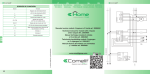
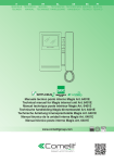
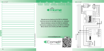
IT
MANUALE
TECNICO
EN
TECHNICAL
MANUAL
FR
MANUEL
TECHNIQUE
NL
TECHNISCHE
HANDLEIDING
ES
MANUAL
TÉCNICO
Manuale tecnico Modulo SimpleHome 9 ingressi Optoisolati e 8 Uscite Relè 16A su
Guida DIN (9I8O16A) Art. 20046606
Technical manual for SimpleHome module with 9 optically coupled inputs and
8 x 16A relay outputs on DIN rail (9I8O16A), Art. 20046606
Manuel technique Module SimpleHome avec 9 entrées opto-isolées et 8 sorties à
relais 16A sur rail DIN (9I8O16A) Art. 20046606
Technische handleiding SimpleHome-module 9 digitale ingangen met opto-isolatie
en 8 relaisuitgangen 16A op DIN-rail (9I8O16A) Art. 20046606
Manual técnico Módulo SimpleHome con 9 entradas optoaisladas y 8 salidas
de relé de 16 A en guía DIN (9I8O16A) art. 20046606
www.comelitgroup.com
AVVERTENZE
• Effettuare l’installazione seguendo scrupolosamente le istruzioni fornite dal costruttore ed in conformità alle norme vigenti.
• Tutti gli apparecchi devono essere destinati esclusivamente all’uso per cui sono stati concepiti. Comelit Group S.p.A.
declina
ogni responsabilità per un utilizzo improprio degli apparecchi, per modifiche effettuate da altri a qualunque titolo e scopo,
per l’uso di accessori e materiali non originali.
• Tutti i prodotti sono conformi alle prescrizioni delle direttive 2006/95/CE (che sostituisce la direttiva 73/23/CEE
e successivi emendamenti) e ciò è attestato dalla presenza della marcatura CE sugli stessi.
• Evitare di porre i fili di montante in prossimità di cavi di alimentazione (230/400V).
WARNING
• Install the equipment by carefully following the instructions given by the manufacturer and in compliance with the standards
in force.
• All the equipment must only be used for the purpose it was designed for. Comelit Group S.p.A. declines any responsibility
for improper use of the apparatus, for modifications made by third parties for any reason or purpose, and for the use of nonoriginal accessories and materials.
• All the products comply with the requirements of the 2006/95/CE directives (which replace directive 73/23/CEE and subsequent amendments), as certified by the CE mark on the products.
• Do not route riser wires in proximity to power supply cables (230/400V).
AVERTISSEMENTS
• E
ffectuer l’installation en suivant scrupuleusement les instructions fournies par le constructeur et conformément aux normes
en vigueur.
• Tous les appareils doivent être strictement destinés à l’emploi pour lequel ils ont été conçus. La société Comelit Group
S.p.A. décline toute responsabilité en cas de mauvais usage des appareils, pour des modifications effectuées par d’autres
personnes pour n’importe quelle raison et pour l’utilisation d’accessoires et matériaux non d’origine.
• Tous les produits sont conformes aux prescriptions de la directive 2006/95/CE (qui remplace la directive 73/23/CEE et
amendements successifs). Cela est attesté par la présence du marquage CE sur les produits.
• Éviter de placer les fils de montant à proximité des câbles d’alimentation (230/400V).
WAARSCHUWINGEN
• V
oer de installatiewerkzaamheden zorgvuldig uit volgens de door de fabrikant gegeven instructies en met inachtneming van
de geldende normen.
• Alle componenten mogen alleen gebruikt worden voor de doeleinden waarvoor ze zijn ontworpen. Comelit Group S.p.A. is
niet verantwoordelijk voor oneigenlijk gebruik van de apparatuur, voor wijzigingen die om welke reden dan ook door derden
zijn aangebracht, en voor het gebruik van accessoires en materialen die niet door de fabrikant zijn aangeleverd.
• Alle producten voldoen aan de eisen van de richtlijn 2006/95/EG (die de richtlijn 73/23/EEG en latere wijzigingen vervangt).
Dit wordt bevestigd door het CE-label op de producten.
• Monteer de aders van de stamleiding niet in de nabijheid van voedingskabels (230/400V).
ADVERTENCIAS
• L
a instalación se ha de efectuar en conformidad con las normas vigentes, siguiendo atentamente las instrucciones suministradas por el fabricante.
• Todos los aparatos deben destinarse exclusivamente al uso para el cual han sido construidos. Comelit Group S.p.A. declina
toda responsabilidad por el uso impropio de los aparatos, por cambios efectuados por terceros por cualquier motivo o
finalidad y por el uso de accesorios y materiales no originales.
• Todos los productos son conformes a los requisitos de las Directivas 2006/95/CE (que sustituye la Directiva 73/23/CEE y
sucesivas enmiendas) como demuestra la presencia de la marca CE en ellos.
• No poner los cables de la columna montante cerca de los cables de alimentación (230/400V).
2
IT
ART. 20046606 – MODULO SIMPLEHOME 9 INGRESSI OPTOISOLATI
E 8 USCITE RELÈ 16A SU GUIDA DIN (9I8O16A)
Modulo su bus caratterizzato da 8 ingressi + 1 ingresso scenario e da 8 uscite a relè con contatto in scambio con comune
indipendente in grado di pilotare carichi elettrici di tipo resistivo fino a 16A. Per carichi non resistivi è consigliato l’utilizzo di un
contattore in appoggio ad ogni uscita.
CARATTERISTICHE TECNICHE
Tensione di alimentazione
24Vdc ± 5%
Assorbimento
min 8mA, max 220mA
Ingressi
8+1 di tipo digitale optoisolato
Uscite
8 a relè 230Vac, 16A resistivi (cosj = 1)
Lunghezza max cavo in ingresso
25m
Protezioni
contro inversioni di polarità
Segnalazioni
1 LED di segnalazione stato bus: lampeggiante indica la trasmissione di dati sul bus,
acceso fisso indica la mancanza del negativo di alimentazione o un collegamento errato del
dispositivo
9 LED di segnalazione stato ingressi
8 LED di segnalazione stato uscite
Mancanza e ripristino
dell’alimentazione
memoria dello stato delle uscite
Morsetti
estraibili per connessione BUS
Posizionamento
su guida DIN o in scatole di derivazione
Riferimenti normativi
compatibilità elettromagnetica: EN 50081-1 (Emissioni di disturbi)
e EN50082-2 (Resistenza ai disturbi)
Omologazioni
CE
Temperatura di funzionamento
da 0° a 50°C
Temperatura d’immagazzinamento
da -10° a +70°C
Umidità dell’aria relativa
da 5 a 95% senza condensazione
Peso
380g escluso imballo
Dimensioni
160x90x58mm (9 moduli DIN)
MORSETTI DI COLLEGAMENTO
Mors
Funzione
Mors
Funzione
Mors
Funzione
-
Negativo alimentazione BUS
I1
Ingresso 1
NC4
Uscita 4 – Contatto NC
+
+24Vdc alimentazione BUS
IS
Comando multiplo (scenario)
NO5
Uscita 5 – Contatto NO
D
Linea BUS dati
NO1
Uscita 1 – Contatto NO
C5
Uscita 5 – Comune
K
Comune
C1
Uscita 1 – Comune
NC5
Uscita 5 – Contatto NC
V-
Negativo di appoggio
NC1
Uscita 1 – Contatto NC
NO6
Uscita 6 – Contatto NO
V+
+24Vdc di appoggio
NO2
Uscita 2 – Contatto NO
C6
Uscita 6 – Comune
I8
Ingresso 8
C2
Uscita 2 – Comune
NC6
Uscita 6 – Contatto NC
I7
Ingresso 7
NC2
Uscita 2 – Contatto NC
NO7
Uscita 7 – Contatto NO
I6
Ingresso 6
NO3
Uscita 3 – Contatto NO
C7
Uscita 7 – Comune
I5
Ingresso 5
C3
Uscita 3 – Comune
NC7
Uscita 7 – Contatto NC
I4
Ingresso 4
NC3
Uscita 3 – Contatto NC
NO8
Uscita 8 – Contatto NO
I3
Ingresso 3
NO4
Uscita 4 – Contatto NO
C8
Uscita 8 – Comune
I2
Ingresso 2
C4
Uscita 4 – Comune
NC8
Uscita 8 – Contatto NC
N.B. Il modulo deve essere programmato tramite la linea BUS utilizzando l’interfaccia SimpleHome/RS232 (20022611) ed il
software di programmazione SimpleProg.
Le specifiche sono soggette a variazioni senza preavviso.
3
ART. 20046606 - SIMPLEHOME MODULE WITH 9 OPTICALLY COUPLED INPUTS
AND 8 X 16A RELAY OUTPUTS ON DIN RAIL (9I8O16A)
Module on bus has 8 inputs + 1 scenario input, as well as 8 relay outputs with switching contact with independent common capable of
controlling resistive electrical loads up to 16A. For non-resistive loads, it is best to use a support contactor at each output.
EN
Technical characteristics
Power supply voltage
24 Vdc ± 5%
Absorption
min. 8 mA, max. 220 mA
Inputs
8+1, optically coupled digital type
Outputs
8 relay 230 Vac, resistive 16A (cosj = 1)
Max. input cable length
25 m
Protection
against reverse polarity
Indications
1 bus status indicator LED: when flashing, indicates data transmission via bus, when lit
steadily indicates lack of power supply negative or incorrect device connection
9 input status indicator LEDs
8 output status indicator LEDs
Lack and restoring of
power supply
output status memory
Terminals
removable for BUS connection
Positioning
on DIN rail or in junction boxes
Applicable standards
electromagnetic compatibility: EN 50081-1 (interference emission)
and EN50082-2 (resistance to interference)
Approvals
CE
Operating temperature
0° to 50°C
Storage temperature
-10° to +70°C
Relative air humidity
5 to 95% with no condensation
Weight
380 g (not including packaging)
Dimensions
160x90x58 mm (9 DIN modules)
CONNECTION TERMINALS
Term.
Function
Term.
Function
Term.
Function
-
BUS power supply negative
I1
Input 1
NC4
Output 4 – NC contact
+
BUS power supply +24 Vdc
IS
Multiple command (scenario)
NO5
Output 5 – NO contact
D
BUS data line
NO1
Output 1 – NO contact
C5
Output 5 – Common
K
Common
C1
Output 1 – Common
NC5
Output 5 – NC contact
V-
Support negative
NC1
Output 1 – NC contact
NO6
Output 6 – NO contact
V+
+24 Vdc support
NO2
Output 2 – NO contact
C6
Output 6 – Common
I8
Input 8
C2
Output 2 – Common
NC6
Output 6 – NC contact
I7
Input 7
NC2
Output 2 – NC contact
NO7
Output 7 – NO contact
I6
Input 6
NO3
Output 3 – NO contact
C7
Output 7 – Common
I5
Input 5
C3
Output 3 – Common
NC7
Output 7 – NC contact
I4
Input 4
NC3
Output 3 – NC contact
NO8
Output 8 – NO contact
I3
Input 3
NO4
Output 4 – NO contact
C8
Output 8 – Common
I2
Input 2
C4
Output 4 – Common
NC8
Output 8 – NC contact
N.B. The module must be programmed vis the BUS line, using the SimpleHome/RS232 interface (20022611) and the SimpleProg
programming software.
Specifications are subject to change without notice.
4
FT SH20
ART. 20046606 – MODULE SIMPLEHOME 9 ENTRÉES OPTO-ISOLÉES
ET 8 SORTIES À RELAIS 16A SUR RAIL DIN (9I8O16A)
Module sur bus présentant 8 entrées + 1 entrée scénario et 8 sorties à relais avec contact en échange avec commun indépendant
en mesure de piloter des charges électriques de type résistif jusqu'à 16A. Pour les charges non résistives, il est conseillé d’utiliser un
contacteur en appui sur chaque sortie.
CARACTÉRISTIQUES TECHNIQUES
24Vcc ± 5%
Absorption
min 8mA, max 220mA
Entrées
8+1 numériques opto-isolées
Sorties
8 à relais 230Vca, 16A résistives (cosj = 1)
Longueur maxi câble en entrée
25 m
Protections
contre les inversions de polarité
Témoins
1 LED de signalisation état bus : clignote pour indiquer la transmission des données sur le
bus, s'allume pour indiquer l'absence du négatif d'alimentation ou une connexion défectueuse du dispositif
9 LED de signalisation état des entrées
8 LED de signalisation état des sorties
Absence et réarmement
de l'alimentation
mémoire de l'état des sorties
Bornes
amovibles pour connexion BUS
Emplacement
sur rail DIN ou dans des boîtiers de dérivation
Normes de référence
compatibilité électromagnétique : EN 50081-1 (Émission de perturbations)
et EN50082-2 (Résistance aux perturbations)
Homologations
CE
Température de fonctionnement
de 0°C à 50°C
Température de stockage
de -10° à +70°C
Humidité relative de l'air
de 5 à 95% sans condensation
Poids
380 g hors emballage
Dimensions
160x90x58mm (9 modules DIN)
FR
Tension d'alimentation
BORNES DE CONNEXION
Borne
Fonction
Borne
Fonction
Borne
Fonction
-
Négatif alimentation BUS
I1
Entrée 1
NC4
Sortie 4 – Contact NF
+
+24Vcc alimentation BUS
IS
Commande multiple (scénario)
NO5
Sortie 5 – Contact NO
D
Ligne BUS données
NO1
Sortie 1 – Contact NO
C5
Sortie 5 – Commun
K
Commun
C1
Sortie 1 – Commun
NC5
Sortie 5 – Contact NF
V-
Négatif d'appui
NC1
Sortie 1 – Contact NF
NO6
Sortie 6 – Contact NO
V+
+24Vcc d'appui
NO2
Sortie 2 – Contact NO
C6
Sortie 6 – Commun
I8
Entrée 8
C2
Sortie 2 – Commun
NC6
Sortie 6 – Contact NF
I7
Entrée 7
NC2
Sortie 2 – Contact NF
NO7
Sortie 7 – Contact NO
I6
Entrée 6
NO3
Sortie 3 – Contact NO
C7
Sortie 7 – Commun
I5
Entrée 5
C3
Sortie 3 – Commun
NC7
Sortie 7 – Contact NF
I4
Entrée 4
NC3
Sortie 3 – Contact NF
NO8
Sortie 8 – Contact NO
I3
Entrée 3
NO4
Sortie 4 – Contact NO
C8
Sortie 8 – Commun
I2
Entrée 2
C4
Sortie 4 – Commun
NC8
Sortie 8 – Contact NF
N.B. Le module doit être programmé via la ligne BUS en utilisant l’interface SimpleHome/RS232 (20022611) et le logiciel de
programmation SimpleProg.
Les caractéristiques techniques sont sujettes à variations sans préavis.
5
ART. 20046606 - SIMPLEHOME MODULE 9 INGANGEN MET OPTO-ISOLATIE
EN 8 RELAISUITGANGEN 16A OP DIN-RAIL (9I8O16A)
Module op bus met 8 ingangen + 1 scenario-ingang en 8 relaisuitgangen met wisselcontact met onafhankelijke gemeenschappelijke
lijn voor het beheren van elektrische gebruikers van het resistieve type, tot 16A. Voor niet-resistieve gebruikers wordt aanbevolen voor
iedere uitgang een contactgever te gebruiken.
NL
Technische gegevens
Voedingsspanning
24Vdc ± 5%
Stroomverbruik
min. 8mA, max. 220mA
Ingangen
8+1 digitaal met opto-isolatie
Uitgangen
8 met relais 230Vac, 16A resistief (cosj = 1)
Max. lengte ingaande kabel
25m
Bescherming
tegen omkering van polariteit
Signaleringen
1 LED voor status bus: als hij knippert wijst dit op gegevensoverdracht op de bus, als hij vast
brandt wijst dit op ontbreken van de min van de voeding of een verkeerde aansluiting van het
apparaat
9 LED's voor status ingangen
8 LED's voor status uitgangen
Uitval en herstel
van de voeding
geheugen van de status van de uitgangen
Klemmen
kunnen naar buiten getrokken worden voor BUS-aansluiting
Plaatsing
op DIN-rail of in aftakdoos
Referentienormen
elektromagnetische compatibiliteit: EN 50081-1 (Ruisemissie)
en EN50082-2 (Weerstand tegen ruis)
Homologaties
EG
Bedrijfstemperatuur
van 0° tot 50°C
Opslagtemperatuur
van -10° tot +70°C
Relatieve luchtvochtigheid
van 5 tot 95% zonder condensatie
Gewicht
380g exclusief verpakking
Afmetingen
160x90x58mm (9 DIN-modules)
AANSLUITKLEMMEN
Klem
Functie
Klem
Functie
Klem
Functie
-
Min voeding BUS
I1
Ingang 1
NC4
Uitgang 4 – NC contact
+
+24Vdc voeding BUS
IS
Meervoudige bediening (scenario)
NO5
Uitgang 5 – NO contact
Uitgang 5 – Gemeenschappelijk
Z
Datalijn BUS
NO1
Uitgang 1 – NO contact
C5
K
Gemeenschappelijk
C1
Uitgang 1 – Gemeenschappelijk
NC5
Uitgang 5 – NC contact
V-
Min ondersteuning
NC1
Uitgang 1 – NC contact
NO6
Uitgang 6 – NO contact
V+
+24Vdc ondersteuning
NO2
Uitgang 2 – NO contact
C6
Uitgang 6 – Gemeenschappelijk
I8
Ingang 8
C2
Uitgang 2 – Gemeenschappelijk
NC6
Uitgang 6 – NC contact
I7
Ingang 7
NC2
Uitgang 2 – NC contact
NO7
Uitgang 7 – NO contact
I6
Ingang 6
NO3
Uitgang 3 – NO contact
C7
Uitgang 7 – Gemeenschappelijk
I5
Ingang 5
C3
Uitgang 3 – Gemeenschappelijk
NC7
Uitgang 7 – NC contact
I4
Ingang 4
NC3
Uitgang 3 – NC contact
NO8
Uitgang 8 – NO contact
I3
Ingang 3
NO4
Uitgang 4 – NO contact
C8
Uitgang 8 – Gemeenschappelijk
I2
Ingang 2
C4
Uitgang 4 – Gemeenschappelijk
NC8
Uitgang 8 – NC contact
NB De module moet worden geprogrammeerd via de BUS-lijn met behulp van de SimpleHome/RS232 interface (20022611) en de
programmeersoftware SimpleProg.
De specificaties kunnen zonder voorafgaande kennisgeving worden gewijzigd.
6
ART. 20046606 - MÓDULO SIMPLEHOME CON 9 ENTRADAS OPTOAISLADAS
Y 8 SALIDAS DE RELÉ DE 16 A EN GUÍA DIN (9I8O16A)
Módulo en bus caracterizado por 8 entradas + 1 entrada escenario y 8 salidas de relé con contacto en intercambio y común
independiente capaz de gobernar cargas eléctricas de tipo resistivo de hasta 16 A. Para cargas no resistivas, se recomienda utilizar
un contactor de apoyo en cada salida.
Características técnicas
Tensión de alimentación
24 Vcc ± 5%
Absorción
mín. 8mA y máx. 220mA
Entradas
8+1 de tipo digital optoaisladas
Salidas
8 de relé de 230 Vca y 16A resistivos (cosj =1)
Longitud máx. del cable en entrada
25m
Protecciones
contra inversiones de polaridad
Señalizaciones
1 Led de señalización del estado del bus: si parpadea, indica que se están transmitiendo
datos por el bus; encendido de forma fija, indica que falta el negativo de alimentación o que
la conexión del dispositivo es errónea.
9 leds de señalización del estado de las entradas
8 leds de señalización del estado de las salidas
Corte y restablecimiento
de la alimentación
memoria del estado de las salidas
Bornes
extraíbles para conexión BUS
Instalación
en guía DIN o en cajas de derivación
Normas de referencia
Compatibilidad electromagnética: EN 50081-1 (Emisión de interferencias)
y EN50082-2 (Inmunidad a interferencias)
Homologaciones
CE
Temperatura de funcionamiento
de 0°C a 50°C
Temperatura de almacenamiento
de -10° a +70°C
Humedad relativa del aire
de 5 a 95% sin condensación
Peso
380g sin embalaje
Dimensiones
160x90x58 mm (9 módulos DIN)
ES
BORNES DE CONEXIÓN
Borne
Función
Borne
Función
Borne
Función
-
Negativo de alimentación BUS
I1
Entrada 1
NC4
Salida 4 – Contacto NA
+
+24 Vcc de alimentación BUS
IS
Mando múltiple (escenario)
NO5
Salida 5 – Contacto NA
D
Línea BUS datos
NO1
Salida 1 – Contacto NA
C5
Salida 5 – Común
K
Común
C1
Salida 1 – Común
NC5
Salida 5 – Contacto NA
V-
Negativo de apoyo
NC1
Salida 1 – Contacto NA
NO6
Salida 6 – Contacto NA
V+
+24 Vcc de apoyo
NO2
Salida 2 – Contacto NA
C6
Salida 6 – Común
I8
Entrada 8
C2
Salida 2 – Común
NC6
Salida 6 – Contacto NA
I7
Entrada 7
NC2
Salida 2 – Contacto NA
NO7
Salida 7 – Contacto NA
I6
Entrada 6
NO3
Salida 3 – Contacto NA
C7
Salida 7 – Común
I5
Entrada 5
C3
Salida 3 – Común
NC7
Salida 7 – Contacto NA
I4
Entrada 4
NC3
Salida 3 – Contacto NA
NO8
Salida 8 – Contacto NA
I3
Entrada 3
NO4
Salida 4 – Contacto NA
C8
Salida 8 – Común
I2
Entrada 2
C4
Salida 4 – Común
NC8
Salida 8 – Contacto NA
N.B.: El módulo se debe programar mediante la línea BUS utilizando la interfaz SimpleHome/RS232 (20022611) y el software de
programación SimpleProg.
El fabricante se reserva el derecho de modificar las características de sus productos, en cualquier momento y sin preaviso.
7
LEGENDA
(bus): verde
(+): rosso
(-): blu
EN
LEGEND
(bus): green
(+): red
(-): blue
FR
LÉGENDE
(bus) : vert
(+) : rouge
(-) : bleu
NL
LEGENDA
(bus): groen
(+): rood
(-): blauw
ES
LEYENDA
(bus): verde
(+): rojo
(-): azul
(bus)
(+)
(-)
3° edizione 05/2012 cod. 2G40000632
IT