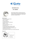
Download Technical manual for programming Serial Bridge Art
Transcript
EN TECHNICAL MANUAL ON 1 2 3 4 5 6 Technical manual for programming Serial Bridge Art. 20003101 www.comelitgroup.com INDEX Accessing the device for the first time................................................................................................................. 2 Description of the interface.................................................................................................................................... 3 Reset......................................................................................................................................................................... 3 Setup .. ...................................................................................................................................................................... 3 Setup / Date and time ............................................................................................................................................................. 4 Setup / Timer enabling............................................................................................................................................................ 4 Setup / Consumption.............................................................................................................................................................. 5 Setup / Consumption / Display.......................................................................................................................................... 5 Setup / Consumption / Setpoints...................................................................................................................................... 5 Setup / Consumption / Rates............................................................................................................................................. 6 Setup / Consumption / Settings........................................................................................................................................ 6 Setup / Consumption / Reset............................................................................................................................................. 6 Setup / User Codes.................................................................................................................................................................. 6 Setup / Dynamic DNS.............................................................................................................................................................. 6 Setup / Advanced.................................................................................................................................................................... 7 Setup / Advanced / General Parameters.......................................................................................................................... 7 Setup / Advanced / Network.............................................................................................................................................. 9 Port forwarding for remote connection......................................................................................................................... 9 Setup / Advanced / Timers.............................................................................................................................................. 10 Recipient definition........................................................................................................................................................ 10 Setup / Advanced / Rules................................................................................................................................................ 11 Setup / Advanced / Scenarios......................................................................................................................................... 11 Setup / Advanced / User and installer code.................................................................................................................. 12 Setup / Advanced / Update Configurations................................................................................................................... 12 Setup / Advanced / Update product............................................................................................................................... 12 Accessing the device for the first time The factory setting for the device IP address is 192.168.1.252. √√ Your PC must therefore be configured with an IP (code identifying a device connected to a network) which is part of the subnetwork, i.e. with an address between 192.168.1.1 and 192.168.1.254. 192 . 168 . 1 . 2 IP address: the last value must be between 1 and 254 excluding: 252 (assigned to serial bridge Art. 20003101) and the values already assigned to other devices connected to the network To access the WEB interface: 1. Power up the device and connect it to the local network using a LAN cable. bridge 17:14 - 07/04/2014 2. Open the browser. 3. Enter the address http://192.168.1.252 in the address bar and press enter. To access the Setup section, press the button and enter the user password (default = 111111) (see chapter "SETUP / ADVANCED / USER AND INSTALLER CODE" to set a new password). Setup CAUTION: To configure outputs, home automation modules... see the technical manual for the SimpleHome system, which is available on the website www.comelitgroup.com. To import the home automation settings from SimpleHome configuration software via SD Card, see the chapter Setup / Advanced / Update configurations. Alarm system configurations are acquired via the Bridge, directly from the anti-intrusion BUS (for VEDO control units). To configure intrusion areas and intrusion zones using Safe Manager, see the technical manual for programming VEDO series alarm control units, which is available on the website www.comelitgtoup.com. Once module configuration is complete, we recommend making an exact copy of the entire contents of the SD card and archiving the information. Connected 2 Description of the interface 1 bridge 0.00kW 17:14 - 07/04/2014 2 3 Alarm Climate Other Shutters Lights Irrigation 1. Current page header. 2. "Date and consumption" toolbar. 3. Buttons for accessing the internal pages used to view and control the available functions and to configure the device. 4. Connection and authentication status message (connected, not authenticated, not authorised...). 5. Logout button. Press Alarm/Climate/Other.... to access the respective sections. Press Automations Consumption Setup Press Configuration 4 17:14 - 07/04/2014 Connected Reset 5 to return to the initial screen. Configuration 17:14 - 07/04/2014 to return to the previous screen. Date and time Date and time Enable Timers Enable Timers Consumption User codes The reset button can be used to: safely disconnect the SD card, restore the network information and restore the factory settings. Consumption SD CARD EJECT Disconnect the SD card User codes Dynamic DNS Advanced NETW RESET Restore the factory settings Firmware: IP address: 172.24.2.186 Subnet Mask: 255.255.0.0 Gateway: 172.24.255.254 Primary DNS: 172.24.0.30 Secondary DNS: 172.24.0.44 MAC address: 00:04:A3:CE:D5:75 TOTAL RESET Connected Restore the factory settings on the device 1.Press and hold the Reset button for 2 seconds. Dynamic DNS 2.When the POWER/STATUS LED flashes more quickly, remove the SD card from the slot. Advanced Firmware: IP address: 172.24.2.186 Subnet Mask: 255.255.0.0 1.Press and hold the Reset button for 5 seconds. Gateway: 172.24.255.254 2.When the 172.24.0.30 POWER/STATUS LED flashes even Primary DNS: Secondary DNS: 172.24.0.44 more quickly, the network settings will be restored MAC address: 00:04:A3:CE:D5:75 to the factory values and the device will restart automatically with the IP address 192.168.1.252. Connected 1.Press and hold the Reset button for 10 seconds. 2.When the POWER/STATUS LED flashes at maximum speed, the factory settings will be restored and the device will restart automatically with the factory settings in place. 2 sec. speed 1 5 sec. speed 2 10 sec. speed 3 CAUTION: ALWAYS disconnect the SD CARD before removing it. CAUTION: The SD CARD must be inserted during the network and factory settings reset. Once the network and factory settings reset is complete, you must wait for the device to restart. When the total reset procedure is carried out, all system configurations saved previously will be deleted. Setup bridge Setup 17:14 - 07/04/2014 Enter User Password Configuration 17:14 - 07/04/2014 Date and time Enable Timers Consumption User codes Dynamic DNS Advanced Firmware: IP address: 172.24.2.186 Subnet Mask: 255.255.0.0 Gateway: 172.24.255.254 Primary DNS: 172.24.0.30 Secondary DNS: 172.24.0.44 MAC address: 00:04:A3:CE:D5:75 Connected 3 This menu can be used to configure the date and time, enable timers (configured via Setup/ Advanced), set consumption setpoints and rates, change the user code, set a dynamic DNS address and access advanced settings. 1. Press Setup to access the menu. 2. Enter the user password (default = 111111) and confirm. 3. Select the menu entry you want to configure. Setup / Date and time This menu can be used to set the device Date and time, as well as the Astronomical dawn/dusk device. Date and time Date and time Date and time: the values can only be changed when enable NTP is deactivated. Date and time Date and time DD/MM/YYYY 14/04/2014 HH:MM 10:01 Enable NTP (automatic time/date from Internet) Time difference (GMT +1:00) Rome, Brussels. Copenhag Automatic switch to DST Automatic (Europe only) Astronomical dawn/dusk device Sunrise: 06:34 - Sunset: 20:05 Enable NTP (automatic time/date from Internet):Date enables updating of date and time via and automatic time the web. Only works if the bridge is connected to the Internet. Time difference: select the reference time difference. Date and time DD/MM/YYYY 14/04/2014 Date and time Automatic switch to DST: select "Automatic (Europe only)" to set the automatic switch to DST. HH:MM 10:01 (only with enable select "SpecifyEnable date" to(automatic specifytime/date the time interval NTP from Internet)in which DST is applied. NTP active) Time difference (GMT +1:00) Rome, Brussels. Copenhag Automatic switch to DST Use the stop as a decimal point Specify date Latitude: 45.8782 N Longitude: 9.9746 E Sunrise variation: 0min Sunset variation: 0min From: 15 / 3 To: 15 / 9 Astronomical dawn/dusk device Astronomical dawn/dusk device Save Sunrise: 06:34 - Sunset: 20:05 Sends commands at sunset and sunriseUse (see according to the latitude and the Setup/Advanced/Rules), stop as a decimal point longitude of the installation site (to avoid Latitude: installation of external dawn/dusk devices). 45.8782 N Connected Longitude: 9.9746 E Latitude / Longitude: s et the relevant coordinates for automatic updating of the dawn/dusk clock. Sunrise variation: 0min Sunrise variation / Sunset variation: adjust these values to bring the sunrise and sunset times Sunset variation: 0min forward or set them back. Save For example: if you want to switch on the outside lights at sunset, leave the sunset Connected variation at 0. If you want to switch them off 2 hours before sunrise, set the sunrise variation to -120 min. Setup / Timer enabling This menu can be used to activate/deactivate the programmed timers (see Setup/Advanced/Timers) and change timer operating times/days. Enable Timers Timer number: select the timer you want to activate (programmed via Setup/Advanced/Timers). "Day" timer Timer number: Timer enabling: enables the selected timer. 2 - Day Timer start: timer start time. The timer start times can be changed. Timer enabling: Enabled days: d ays on which the timer will be started. The timer operating days can be changed. Timer start: HH:MM Enabled days: Th Mo Fr Timer End: HH:MM Enabled days: Th Mo Fr 00:00 Tu Sa 00:00 Tu Sa Save Connected 4 We Su We Su N.B.: with the "virtual timer", the "Timer end" times can also be changed. Setup / Consumption This menu can be used to view the power measured by the load modules or pulse meter to as a production or consumption value, change the maximum consumption setpoints by hour, day, month or year; change the rates by day and time band. Consumption Toolbar: select which meter to monitor via the toolbar on the homepage. Display Currency: enter the currency symbol you want to set for calculating consumption. Thresholds CO2 constant: enter the CO2 constant to monitor the CO2 not released into the atmosphere, in the case of energy production systems (photovoltaic systems...). The "CO2 Saved" graph can be viewed via Home/Consumption. Rates Settings HOME / CONSUMPTION / CO2 SAVED Reset Consumption HOME CO2 Saved bridge Toolbar: 17:14 - 07/04/2014 None Currency: 14/04/2014 0.00kW Graph kg 0kg € CO2 constant: Day 0,000 kg/kWh 0.53100 Setup Save 0 4 8 12 16 20 Connected Connected Setup / Consumption / Display Display meters Description: Visibility This menu can be used to rename the meters connected to the system and select the meters that you wish to view in the consumption menu area. Description: description associated with the meter. Visibility: makes the meter in the consumption menu visible. Electricity Gas Water Input 2 Connected Input 3 Save Setup / Consumption / Setpoints Connected This menu can be used to set the maximum consumption setpoints for hours, days, months and years in order to obtain an immediate visual comparison on the graph and in the consumption table when the set setpoint for the period is exceeded (Yellow = 75% of the set threshold, Red = 100% of the set setpoint). Setpoints "Consumption" setpoints Meter: Meter: select the meter for which you want to set the setpoints. consumption Time 0.00000 kWh Day 0.00000 kWh Month 0.00000 kWh Year 0.00000 kWh Save Connected 5 Time/Month/day/Year: set the maximum consumption setpoint for the corresponding time interval. Setup / Consumption / Rates This menu can be used to set the meter rates according to time bands. The information will then be used to construct the consumption graphs in the Consumption menu (Home/Consumption). 1. Meter: select the meter for which you want to set the setpoints, for example: "Elect. consumption". 2. Rates: set the rates according to time. 3. Time slot: set the start and end of each time band, and associate the time bands with the corresponding rate for every day of the week. Rates Rate: "Electricity production" Meter: Elect. consumption Rates 1 0.09800 €/kWh 2 0.00000 €/kWh 3 0.00000 €/kWh 4 0.00000 €/kWh 5 0.00000 €/kWh AUTION: daily rate programming must refer to the whole 24-hour cycle; any hours not C programmed by the user will be set by the system automatically. Select a rate Time slot: Start: End Mon Tue Wed Thur Fri Sat Sun 0 6 1 1 1 1 1 2 2 6 20 1 1 1 1 1 2 2 20 24 2 2 2 2 2 2 2 Save Setup / Consumption / Settings Connected Settings Unit of measurement: enter the unit of measurement for that meter. "GAS" settings Meter: GAS Unit of measurement: mc Scale factor: This menu can be used to view the settings for the pulse meter module used to measure water, GAS, etc...). Meter: select the meter for which you want to change the settings. Scale factor: enter a multiplication factor if you want to convert different units of measurement (for example: from litres to imperial gallons, 4.54609). 1.00000 Save Connected Setup / Consumption / Reset This menu can be used to reset all meters. Reset count Press "Yes" to reset all meters. 17:14 - 07/04/2014 Reset meters: are you sure? No Yes Setup / User Codes See "Home automation login" in "Setup / Advanced / User and installer code". Setup / Dynamic DNS Connected Dynamic DNS 1. Enable DDNS service: tick this option to enable the DNS service. 2. DNS service: select, for example, Comelit DNS to use the free Comelit service. 3. Press "Comelit DNS registration" and complete user registration (making a note of the data entered) on the website www.comelitdns.com to which you are automatically directed. DNS client not enabled Enable DDNS service: DNS service: ComelitDNS (www.comelitdns.com) Comelit DNS registration: DDNS code: Activation code: 0004A3CED575 C557E350907E74A2 Username (indicate service access username) Password (indicate service access password) Host (indicate dns name) Comelit DNS You must be connected to the Internet to carry out this procedure. User registration Hostname myhostname Email address [email protected] Password •••••••• Confirm password •••••••• .comelitdns.com I have read the terms and conditions of service. Save Connected 6 This menu can be used to associate a dominion name (for remote connection) with the public IP address of the Serial Bridge Art. 20003101. to register the product. A confirmation email will be sent to the email address entered 4. Press during the "user registration" process; follow the instructions in the message to complete the activation procedure. 5. Return to the Serial Bridge WEB page and enter the email address used for registration, the Passion.Technology. Design. password and the submitted hostname in the "Username", "Password" and "Host" fields. Setup / Advanced The advanced settings can be used to configure: the general parameters, network settings, timers, rules, scenarios and user and installer codes, as well as updating the configurations and the product itself. To access the advanced settings: 1. From the home screen, select Setup/Advanced. 2. Enter the installer password (default = 001961). 3. Select the menu entry you want to set. Configuration Advanced 17:14 - 07/04/2014 17:14 - 07/04/2014 Date and time General parameters Enable Timers Network Consumption Timer User codes Dynamic DNS Scenarios 17:14 - 07/04/2014 Enter Installer Password Advanced Setup Rules Advanced User and installer code Update configurations Firmware: IP address: 172.24.2.186 Subnet Mask: 255.255.0.0 Gateway: 172.24.255.254 Primary DNS: 172.24.0.30 Secondary DNS: 172.24.0.44 MAC address: 00:04:A3:CE:D5:75 Update product Connected Connected Setup / Advanced / General Parameters This menu can be used to configure the general device settings: the language, identification name and configuration parameters of the home automation and alarm system. General parameters General parameters General parameters 17:14 - 07/04/2014 17:14 - 07/04/2014 17:14 - 07/04/2014 Select language Select language Italiano Description: Home automation Bus module number: Slave bridge Home automation Bus module number: 201 Master/Slave Italiano Description: bridge Home automation 201 Master/Slave Select language Italiano Description: bridge Slave Bus module number: 201 Master/Slave Slave Transmission time: 30 Transmission time: 30 Transmission time: 30 Number of retries: 3 Number of retries: 3 Number of retries: 3 PANEL (on 485) EnableVEDO Bus toCONTROL TCP: Enable Bus to TCP: Alarm Alarm control panel detected: Alarm Alarm Vedo control panel Communication type: TCP/IP ID address: 1 Device password: •••• IP communication card address: 172.24.2.212 S-SERIES Enable Bus to TCP: CONTROL PANEL : 10012 TLS Alarm control panel detected: Communication type: ID address: Vedo control panel Master/Slave 485 1 Device password: •••• RS485 bus speed: 38400 S-Series control panel Slave Enable RS232 to 485: Enable alarm act. from bus: Enable alarm deact. from bus: Bus activation zone: Save Save Alarm control panel detected: 100 Enable alarm act. from web: Connected Connected Enable alarm deact. from web: Enable alarm to TCP: Save Connected 7 Select language: s elect the menu language. Description: identification name of art. 20003101. Appears on the web page home screen. Home automation BUS module number: number identifying the module on the home automation BUS. It can be used to send "Supervisor commands" over the BUS which can activate scenarios on other supervisors (Planux Manager, etc...). Master/Slave: the type of operation must be set on all supervisors within the system for system management. MASTER must only be selected on one of the supervisors within the system, while all the remaining supervisors must be set as SLAVE. By supervisor we mean Planux Manager, Minitouch, Touch screen, Serial Bridge, etc... Polling time (Master only): c an be used to force module interrogation to maintain system alignment (we recommend setting a high time value so as not to cause traffic on the BUS). Transmission time: the transmission time determines the speed with which the commands are sent over the data line. The higher the value, the greater the time between sending one command and the next. E.g.: Supposing we have 5 lights in one area and we send the switch-on command to all of them. • If the value is set to 2, 2 tenths of a second will pass between one light switching on and the next. • If the value is set to 6, 6 tenths of a second will pass between one light switching on and the next. Number of retries: indicates the number of command re-transmissions in the event that the module under control does not respond. Enable Bus to TCP: enables the serial bridge for operation as a converter between SimpleHome BUS and the LAN with TCP/IP protocol. This function is used by the supervisors, in order to send commands over the home automation BUS via the LAN, or to program home automation modules using the SimpleHome configuration software on a PC connected to the LAN. The port to set on the programming software is 10011. Alarm Alarm control panel detected: s pecify whether the system has an alarm control panel which should communicate with the serial bridge (none / VEDO control panel / S-Series control panel). VEDO control panel(parameters to be set as configured via Safe Manager) Communication type: s elect the type of communication protocol (TCP/IP or 485). ID address: select the device identification number. This corresponds to the BUS address set on the device (via Safe Manager). Device password: enter the password associated with the device (default 0). IP communication card IP address: IP address of the control panel card, control panel port and TLS (TCP/IP communication protocol only). 485 BUS speed: select the RS485 communication BUS speed (485 communication protocol only). The standard speed of VEDO control panels is 38400 baud. S-Series control panel Master/Slave: the type of operation must be set on all supervisors within the system for system management. MASTER must only be selected on one of the supervisors within the system, while all the remaining supervisors must be set as SLAVE. By supervisor we mean Planux Manager, Minitouch, Touch screen, Serial Bridge, etc... Enable RS232 to 485: enables the serial bridge for operation as an RS232/RS485 converter. CAUTION: this function is only active if terminals V+ and V- have a voltage setting of +12 Vdc to +13.8 Vdc. Enable alarm act. from BUS: enables the option of alarm system activation by means of a command over the home automation BUS. Enable alarm deact. from BUS: enables the option of alarm system deactivation by means of a command over the home automation BUS. BUS activation zone: this zone, if the option "Enable alarm activation from BUS" or "Enable alarm deactivation from BUS" is enabled, means the anti-intrusion system can be activated or deactivated with a command made directly from the BUS. If the pre-set value (100) is not changed, the entire system can be activated with a SET command for ZONE 100 or deactivated with a RESET command for zone 100. It is also possible to activate individual alarm control panel zones by means of zone commands, by adding the number of the control panel area you wish to control to the set number. For example, if you want to activate alarm control panel area 3, you need to send a SET command to zone 103 (100+3), or a RESET command to zone 103 to deactivate control panel area 3. Enable alarm act. from WEB: enables the option of alarm system activation via the serial bridge WEB page. Enable alarm deact. from WEB: enables the option of alarm system deactivation via the serial bridge WEB page. Enable Alarm to TCP: enables the serial bridge for operation as a converter between the RS232 serial port on the alarm control unit and the LAN. For operation in this mode, port 10012 must be used on the IP address of the Serial Bridge. 8 Setup / Advanced / Network Network configuration 17:14 - 07/04/2014 Host Name: This menu can be used to configure all device network parameters. Host Name: name identifying the device within the local network. Enable DHCP: enable protocol for dynamic configuration of the device IP address. SAM IP address: address identifying the bridge within the network (default = 192.168.1.252). Enable DHCP: IP address: 192.168.1.252 Gateway: 192.168.1.1 Subnet Mask: 255.255.255.0 Primary DNS: 192.168.1.1 Secondary DNS: 192.168.1.1 HTTP port: 80 HTTPS port: 443 Gateway: IP address of the router to which the device is connected (provided in the router user manual). Subnet Mask: (255.255.255.0). Primary DNS / Secondary DNS: server address for the translation of host names into IP addresses. Set the primary DNS as the IP address of your router. Leave the secondary DNS field empty. HTTP port: web access port (default = 80). HTTPS port: secure web access port (default = 443). Save Connected CAUTION: Incorrect settings could cause the screen to disappear. If you change the IP address of the Serial Bridge, configure your PC with an IP address which is part of its subnetwork (to access web pages locally) and remember to enter the new address in the address bar of your browser. Valid DNS addresses must be entered in the Primary and Secondary DNS fields for the device to work properly. We recommend that the "Enable DHCP" command is not selected, so that the Serial Bridge has a fixed IP address and can therefore always be reached. For remote access, open the HTTP port or the HTTPS port on your router (see the port forwarding procedure below). Port forwarding for remote connection 1. Connect the PC to the router to which the Serial Bridge Art. 20003101 is connected. 2. Access the browser and enter the IP address of the router (this can be found in the router user manual) in the navigation bar, for example: 192.168.1.1 3. Log in by entering the username and password (these can be found in the router user manual). The port configuration method may differ according to the brand and type of router used 4. Search for the sections "Port Opening" or "Apps and games" or "Port Forwarding" (if not displayed on the main menu, search for them in Advanced settings) and add the ports you wish to configure. 5. Fill in the configuration panel (see example in the figure below): a. Enter the name of the application. b. Select TCP protocol. c. For the external port, enter the value* which identifies the HTTP port (e.g. 80) or HTTPS (e.g. 443). Enter the same value in Start and End to open a single port. d. For the internal port, enter the value* which identifies the HTTP port (e.g. 80) or HTTPS (e.g. 443). Enter the same value in Start and End to open a single port. e. Enter the Serial Bridge IP address 192.168.1.252. f. Confirm. * Open the HTTP (for web access) or HTTPS (for secure web access) port by setting the parameters used in the "Network configuration" of the Serial Bridge. If remote connection does not work, try changing the address of the ports to one of the following: 8080 (to open the HTTP port) or 8443 (to open the HTTPS port). Web Server Bridge 80 80 80 80 192 9 168 1 252 Setup / Advanced / Timers From this menu it is possible to set: · a timer for executing a command over the BUS. · a virtual timer to define a time range for executing a rule (see Setup/Advanced/Rules). Timer Timer number: 1- Timer number: number identifying the timer. Up to 32 timers can be entered. Description: • Timer Timer description: description associated with the timer. Virtual 0 Timer: select if you wish to set a timer to transmit commands over the BUS in order to control other modules or systems. 00:00 Virtual: select if you wish to set a virtual timer to carry out actions exclusively within the set time band. The virtual timer can be used from the Rules menu. Timer enabling: Enabling zone association: Timer start: HH:MM Enabled days: Th Recipient: Mo Fr Tu Sa We Su Timer enabling: tick the option to activate the timer. Enabling zone association: a zone number can be associated with a timer in order to enable or disable the latter, for example using a button connected to the home automation BUS set as a zone command. None Save Timer start: times at which the timer will be started. Timer end (virtual timer only): times at which the timer will be deactivated. Connected Timers Enabled days: d ays on which the timer will be started. Recipient: select what will be controlled by the timer (see page 10 "Recipient definition"). Timer number: 1- Description: Timers • Virtual Timer enabling: Enabling zone association: 0 Timer start: HH:MM Enabled days: Th Mo Fr Timer End: HH:MM Enabled days: Th Mo Fr 00:00 Tu Sa We Su 00:00 Tu Sa We Su Save Recipient definition Recipient Connected In timers, rules and scenarios the "Recipient" field defines what is controlled by the timer, the rule or the scenario. Zone Zone: 0 Command: Element on Bridge: select the type of output (lights, automations...) you want to control, the element on the bridge and the type of command (*) (or speed in the case of the "climate" output) you wish to transmit. Supervisor: select the supervisor input number. Scenario: select the number of the scenario you wish to transmit. Module + output: select the module number, the module output number and the type of command (*) you wish to transmit. Zone: s elect the zone number and the type of command (*) you wish to transmit. VEDO control panel/S-series control panel: select the area number and the type of command you wish to transmit. Dimmer 35% Save Connected (*) If the command type is "rule" or "dimmer": move the slider [1] to set the desired intensity. If the command type is "RGB": Click the on the colour bar [2] and select the desired tone on the colour spectrum [3]. Recipient Move the slider to set the Zone desired intensity [4]. Zone: 0 Command: Dimmer 1 Command: RGB 4 2 35% 3 Save Connected Save Connected 10 Setup / Advanced / Rules The rules allow the association of up to 3 anti-intrusion system elements in order to trigger an event that can send commands over both systems. For example, it is possible to switch on a timed light if an alarm control unit input is opened (when a volumetric sensor enters alarm mode) only if an alarm control unit area has been activated. Rule number: n umber identifying the rule. Up to 50 rules can be entered. Rules Rule number: 1 - RULE TEST Description: RULE TEST Description: description associated with the rule. Rule enabling: Rule enabling: tick the option to activate the rule. Element 1 Element type: Timer Element 1/2/3 1-1- Element status: Active Relationship: AND Element 2 Element type: Timer 1-1- Element status: Active Relationship: END True condition Recipient Scenario 1- False condition Recipient Scenario 2- Element type: enter the element to be supervised for the implementation of the rule with the corresponding module number, area number, etc... • • • • • • • • • • • • • OFF (default) Element on Bridge SimpleHome BUS input SimpleHome BUS output Timer (see Setup/Advanced/Timers) Rule (see Setup/Advanced/Rules) Astronomical dawn/dusk device (see Setup/Date and time) Intrusion zone Intrusion zone deactivated Intrusion zone activated Area in alarm Area in entrance delay Area in exit delay CAUTION: if you select "SimpleHome BUS input", the ON/OFF status of a home automation module can be entered in the rule. This input must be set in the programming software as a supervisor input. CAUTION: if you select "Element on Bridge", you will be able to enter one of the elements that can be controlled from the areas available on the home screen in the rule: Lights, Other, Automations, Climate, Irrigation, Shutters. Save Connected Element status: condition to be checked. Relationship: up to 3 elements can be linked in one rule. After entering an element, select AND or OR to move onto the next elements. Select END to close the condition. True / false condition Recipient: select what will be controlled at the end of condition checking (see page 10 "Recipient definition"). Setup / Advanced / Scenarios Up to 32 scenarios can be programmed with 20 elements each, sending commands over the automation or anti-intrusion system. Scenarios Scenario number: n umber identifying the scenario. Scenario number Description: description associated with the scenario. 1- Description: Visible: tick this option to make the scenario visible on the home/scenarios screen. Visible: Element number 1 Element number: Enter the scenario element number. After programming an element, save the configuration and move on to the next element. Recipient: select what will be controlled (see page 10 "Recipient definition"). Recipient None CAUTION: several scenarios can be linked together by adding a second previously saved scenario as an element. Save Connected 11 Setup / Advanced / User and installer code This menu can be used to change both the user code and the installer code. Change codes Home automation login Serial Bridge user code New user code: •••• Re-enter user code: •••• Save New installer code •••• Re-enter installer code •••• Save Connected √√ The code can consist of letters a-z (capitals or lower case) and/or digits 0-9. √√ The password is case-sensitive (a difference is detected between capitals and lower case letters). √√ Min. length 4 characters - Max. 10 characters. Home automation login: the drop-down menu can be used to set the "Home automation login" as: S-series control panels VEDO control panels no user code (default): to access all "user sections" (except SetUp and Alarms) without entering the user password. A user password should nevertheless be set for accessing the Setup and Alarms sections. no user code (default): to access all "user sections" (except SetUp and Alarms) without entering the user password. It is nevertheless necessary to know the "VEDO control panel user code" (configured via Safe Manager*) in order to access the "Alarms" section and set a password for accessing the Setup section. serial bridge user code: to access all "user sections". serial bridge user code: to access all "user sections" (except Alarms). It is nevertheless necessary to know the "VEDO control panel user code" (configured via Safe Manager*) in order to access the "Alarms" section. VEDO control panel user code: to access all "user sections" using the VEDO user code (configured via Safe Manager*). * default 111111 To set a new user code, enter a new password and press "Save". To access the Advanced Setup section, you need to enter the installer code (default = 001961). To set a new installer code, enter a new password and press "Save". Setup / Advanced / Update Configurations 1. 2. 3. 4. 5. Import the settings to SD card using the SimpleHome configuration software. Insert the SD card in the relevant slot. From Setup/Advanced, select "Update configurations". Press "Yes" and wait for the configurations to load. If you want to return to the home screen, enter the address http://192.168.1.252 (or the IP address set in network parameters) in the address bar again and press enter. Update configurations 17:14 - 07/04/2014 Are you sure you want to reload configurations from SD? No Yes The configuration updating procedure does not store data relating to consumption settings, and for this reason this information must be re-entered (setpoints, rates, toolbars, etc...). Setup / Advanced / Update product Select files and press upgrade Firmware: none selected none selected Browse... Browse... Upgrade Connected 12 To update the Firmware press "Browse" and search for the file with extension .cfbl To update the WebPages press "Browse" and search for the file with extension .bin Press "Upgrade" to begin updating and wait for the confirmation message. CAUTION: the version number of the loaded files must match. For example: "X.X" "firmware_20003101_X.X.cfbl" and "webpages_20003101_X.X.bin". 1st edition 05/2014 code 2G40001106 This menu offers access to Serial Bridge software upgrades. Upgrade WebPages: Connected


