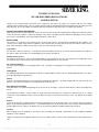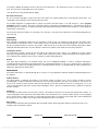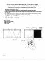
1
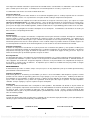
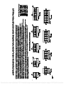
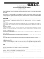
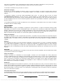
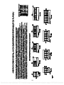
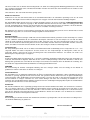
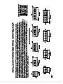
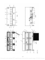
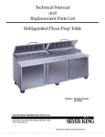
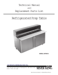
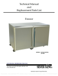
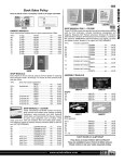
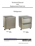
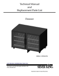
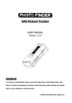
Technical Manual
and
Replacement Parts List
Refrigerated Prep Table
MODEL SKP7218
1600 Xenium Lane North, Minneapolis, MN 55441-3787
Phone (763) 923-2441
1
Specifications Subject to Change Without Notice.
Searchable, web-optimized PDF created using a watermarked evaluation copy of CVISION Maestro
TECHNICAL MANUAL
SILVER KING PREPARATION TABLES
MODELS SKP7218
Thank you for purchasing Silver King food service equipment. Our goal is to provide our customers with the most reliable
equipment in the industry today. Please read this manual and the accompanying warranty information before operating your new
Silver King unit. Be sure to complete and mail the warranty card within 10 days of purchase to validate your warranty.
INSPECT FOR DAMAGE AND UNCRATE
Upon delivery of your new Silver King unit, uncrate at once to inspect for possible freight damage following the instructions printed
on the exterior of the container. Report any damages to the carrier responsible for transportation and promptly present a claim for
any evidence of mishandling. Save all packaging materials if a claim is filed.
INSTALLATION
The stainless steel exterior of the cabinet has been protected by a plastic covering during manufacturing and shipping. This
covering can be readily stripped before installation. After removing this covering, wash the interior and exterior surfaces using a
warm, mild soapy water solution and a sponge or cloth, rinse with clean water and dry.
Legs/Casters
The unit comes with Legs or Casters. To install them, tilt the unit and thread the Legs or Casters into the 4 Rivnuts in the bottom of
the cabinet. Make sure that they are installed tightly to prevent future thread wear.
Condenser Filter Screen
The Condenser Filter Screen, Screen Pull and Filter Guides are packaged inside the unit. The instructions for installing these parts
are included in this technical manual. Do not operate the unit without the filter screen installed!
Pans and Pan Supports
The Pans and Pan Supports are packaged with the unit. Instructions for locating the Pan Supports are included in this technical
manual.
Cutting Board
The Cutting Board Brackets and mounting instructions are shipped with the cabinet. After the Cutting Board Brackets are in place,
the Cutting Board will nest inside them.
Shelves
Inside the unit you will find Shelves and a plastic bag containing Shelf Supports. The Shelf Supports with the “tang” go on the rear
Pilasters. This shelf system allows for easy adjustment to suit your needs.
Door Adjustment and Swing
Should the Door ever require straightening, loosen the Screws on the Hinges, square the Door with the cabinet and retighten the
Screws.
The mounting of the Door is easily reversible on single door units should space or convenience require that you do so. Simply
remove the Screws holding the Hinges, rotate the Door 180 degrees and relocate the Hinges on the side opposite their original
location.
Drawers
To remove the Drawers on drawer models for cleaning, simply open them fully, push the Stop Levers out of the way on the Cabinet
Drawer Tracks while pulling the Drawer out. To reinstall the Drawer, line up the drawer tracks on the cabinet and the Drawer and
push the Drawer into the cabinet. The Drawer Pan can be removed by lifting it out with the Drawer fully extended.
Location
When locating your new refrigerator, convenience and accessibility are important considerations, but the following installation
guidelines must be followed;
*Always avoid placing the refrigerator adjacent to an oven, heating element or hot air source that would affect the operation of the
unit.
1
Searchable, web-optimized PDF created using a watermarked evaluation copy of CVISION Maestro
*For proper ventilation the bottom front of the unit must not be obstructed. The unit must be on legs or casters to raise it off the
floor. The unit can be installed tight on the sides and back.
*The unit must be level or tilted backwards slightly.
Electrical Connections
Be sure to check the data plate, located on the liner of the cabinet, for required voltage prior to connecting the unit to power. The
specifications on the data plate supersede any future discussion.
The standard refrigerator is equipped with an eight (8) foot power cord that requires a 115 Volt, 60 Cycle, 1 Phase properly
grounded electrical receptacle. The power cord comes with a 3 prong plug for grounding purposes. Any attempt to cut off the
grounding spike or to connect to an ungrounded adapter plug will void the warranty, terminate the manufacturers responsibility and
could result in serious injury.
The circuit must be protected with a 15 or 20 ampere fuse or breaker. The unit must be isolated on a circuit and not plugged into an
extension cord.
OPERATION
Initial start up
After satisfying the installation requirements, the refrigerator is ready to start. The Compressor will start when the power cord is
connected to the required power source. If the Compressor does not start when the unit is initially plugged in, check to make sure
that the Temperature Control is not in the “off” position. Allow the unit to run for two hours before loading it with product. When
loading the unit with product, take care not to block the air flow in the cabinet as this would affect the units performance.
Temperature Control
The Temperature Control is located on the back wall of the cabinet liner and is factory set to maintain an average cabinet
temperature of approximately 36 to 40 Deg F. To obtain colder temperatures turn the Temperature Control stem clockwise and vice
versa. Allow the unit a minimum of one hour to respond to a control setting adjustment.
Defrost
Your Silver King refrigerator is an automatic defrost unit and no additional plumbing is required. Automatic defrosting is
accomplished when frost buildup on the Evaporator Coil is cleared during Compressor “off” cycles. Defrost water is collected in a
pan located in the compressor compartment where it is evaporated into the room air. It is important that the unit be installed level to
allow proper drainage of the defrost water.
MAINTENANCE
Preventative maintenance is minimal although these few steps are very important to continued operation and maximizing the life of
the appliance.
Cabinet Surfaces
The cabinet interior is aluminum and stainless steel and the exterior is stainless steel. These surfaces should be cleaned
periodically with a solution of warm water and mild soap, rinsed and wiped dry with a soft cloth. A good stainless steel cleaner can
also be used. Should a surface become stained, do not attempt to clean with an abrasive cleanser or scouring pad. Use a soft
cleanser and rub with the grain of the metal to avoid scratching the surface. Do not use chlorinated cleaners. Always rinse well and
dry after cleaning.
Condenser
Periodically the Condenser Filter Screen must be cleaned. The Condenser Filter Screen is located on the bottom of the cabinet. To
clean it simply pull it out the front of the unit using the Filter Screen Pull and rinse it in a stream of water. Dry the screen by tapping
it on a counter or floor. Replace the filter screen by placing it into the filter screen tracks on the bottom of the unit and sliding it all
the way to the rear of the cabinet. Do not operate the unit without the filter sreen installed!
Door Gasket
The Door Gasket will collect dirt and should be wiped clean with a warm, mild soapy water solution to extend its life and assure
maximum cabinet performance and life.
MODEL
SERIAL NO.
DATE INSTALLED
2
Searchable, web-optimized PDF created using a watermarked evaluation copy of CVISION Maestro
FILTER GUIDES AND SCREEN INSTALLATION INSTRUCTIONS
MODELS: SKF48, SKP72I 8, SKP7230, SKPZ6O, SKPZ92, SKR48, 5KP488, SKP48I 2, SKP48I 8
DO NOT OPERATE UNIT WITHOUT FILTER SCREEN AND AIR CURTAIN INSTALLED
Disconnect unit from power source.
Tip the unit on its back and loosen the 2 screws along the top edge of the base.
Insert tab on the end of the filter guide with curtain into the slot located along the lower edge of
the base unit
Slip the opposite end of the filter guide with curtain under the screw head loosened in step 2,
pull forward, and lighten screw to secure the filter guide to base.
Repeat step 4 with right filter guide.
Insert filter screen into tracks formed by the guides and slide back until the screen stops.
Install legs or casters.
Return unit to original upright position.
This kit includes:
- Filter guide with curtain
- Right filter guide
- Filter screen
STEP 4
STEP 6
RI GIlT HAND
FILTER GUIDE
EH_L:
STEP 5
FILTER GUIDE
Vv1THCURTPJN
TAB
STEP 3
2541g
REV G
3
Searchable, web-optimized PDF created using a watermarked evaluation copy of CVISION Maestro
4
Searchable, web-optimized PDF created using a watermarked evaluation copy of CVISION Maestro
I400EL SKPZ?B
iia
P2I2
fila. XP4S3
ca
WP4F.IS
EH.. SKP42IZ
111.1.111
TOE' IEWS SHOMJ 1Mm PNJ COVERS REMO
DOEL
KPO24
I4DDEL SKPW[b
11111111 Ii
w
7
3(12.50
0007233
3 (LOlO)
0005024
5007210
4 LOlO)
7
7
s
I IL01100
OIIr-TO-osct
0(04000
0000000
SOPH812
orNa
0002702
00P2)D
I000_
H_ S(P)2
flOua OOP?210
w
10 (SHOOT)
O (Soar)
-
O S000D
4 (OHF0
O
SIOG-m-OIO&
ADAPTEP RAPI SUPPLIED WITH UNIT
IiiiiIiiIÍi!Il
Ail "P series prop tables aro supplied wth a serios of Pan Adaptor Bars as shown in the table at the righL
Locate your model prep table below to aid in the installation of the Pn Adapter Bars On a model SKP27B prep
table the single Pari Adapter Bar
mounts side-to-side and locks in place on Uhe Side Pan Supports 'C' as
showi. Models SKP4BB. SKP4BI 2, SKPBOI B & SkP721 B are supplied ith a number of front-to-beck Pan Adapter Bers 'A'
that lock In the Front and Rear Pan Supports D' In the locations shown. Model KP271 2, SKP4.81 S, SKP5024 & SKP7230
mega top prep tables are supplied with en assortment of Pan Adapter Bars es r ioted in the table at the righL
To set up these units, first InstaJl the front-to-back Pan Adapter Bars A In the le caons slion These bars
lock in place ori the Front and Rear Pan Supports O'. Next install the side-to-sicJe Pan Adapter Bars 'B' in
the positions sIiown. Aitemate Pan Adapter Bar arrangements can be made b moving, deleting or adding bars
INSTALLA11ON INSTRUC1ThONS FOR PAN ADAPTER BARS
MANUAL TECNICO
TABLAS DE PREPARACION SILVER KING
MODELOS SKP7218
Gracias por comprar la maquinaria de servicios de alimentación Silver King. Nuestro objetivo es otorgar a nuestros clientes la
mejor maquinaria de la industria actual. Sírvase leer este manual y la información acerca de la garantía que lo acompaña antes de
poner en funcionamiento su nueva unidad Silver King. Asegúrese de completar y enviar por correo la tarjeta de garantía dentro de
los 10 días posteriores a la compra a fin de ratificar su garantía.
INSPECCIONE LA UNIDAD EN BUSCA DE DAÑOS Y DESEMBALE
Cuando reciba su nueva unidad Silver King, desembálela inmediatamente y controle que no haya sufrido daños durante el
transporte siguiendo las instrucciones impresas en la parte externa del envase. Si encuentra daños, infórmelo a la empresa
responsable del transporte y presente inmediatamente un reclamo ante cualquier prueba de maltrato. Si presenta un reclamo,
conserve todo el material de embalaje.
INSTALACION
El exterior del gabinete de acero inoxidable ha sido protegido por una cubierta de plástico en la fabricación y envío. Esta cubierta
puede ser retirada antes de la instalación. Una vez retirada la cubierta, lave las superficies internas y externas utilizando una
solución de agua jabonosa y tibia y una esponja o paño, enjuague con agua limpia y seque.
Patas/Rueditas
La unidad trae patas o rueditas. Para instalarlas, incline la unidad y enrosque las Patas o Rueditas en las 4 Tuercas ubicadas en la parte inferior del gabinete.
Asegúrese que estén ajustadas para prevenir el futuro desgaste de las roscas.
Pantalla de Filtro Condensadora
La Pantalla de Filtro Condensadora, el Tirador de la Pantalla, y las Guías del Filtro están embaladas dentro de la unidad. Las
instrucciones para instalarlas están incluidas en este manual ¡No ponga la unidad en funcionamiento antes de instalar la pantalla!
Paneles y Soportes
Los Paneles y sus Soportes están embalados dentro de la unidad. En este manual encontrará las instrucciones para colocar los
Soportes de los Paneles.
Tabla de Cortar
Las Ménsulas para Tabla de Cortar y las instrucciones para su instalación son enviadas con el gabinete. Luego de haber colocado
las Ménsulas para la Tabla de Cortar, colóquela dentro de las mismas.
Estantes
Dentro de la unidad encontrará Estantes y una bolsa de plástico con los soportes de los mismos. Los Soportes que tienen una
“cola” van colocados en las pilastras traseras. Este sistema de estantes permite ajustar fácilmente los estantes conforme a sus
necesidades.
Ajuste y Vaivén de la Puerta
En caso de necesitar enderezar la puerta, afloje los Tornillos en las Bisagras, alinee la Puerta con el gabinete y ajuste los Tornillos
nuevamente.
El engaste de la puerta es fácilmente reversible en las unidades de una sola puerta si usted desea hacerlo por cuestiones de
espacio o conveniencia. Simplemente retire los Tornillos que sostienen las Bisagras, rote la puerta 180 grados y coloque las
Bisagras en el lado opuesto a su ubicación original.
Cajones
Si desea retirar los Cajones ubicados en los módulos de cajones para limpiarlos, simplemente ábralos en forma completa y retire la
Palanca de Tope en las Guías de los Cajones mientras que extrae el Cajón. Para volver a colocar el cajón, alinee las guías de los
cajones en el gabinete y el Cajón y coloque el Cajón dentro del gabinete. Puede retirar el Panel de Cajones levantándolo y
extrayéndolo con el Cajón totalmente extendido.
Ubicación
Al elegir una ubicación para su nuevo refrigerador, debe tener en cuenta la conveniencia y facilidad de acceso, pero debe seguir
las siguientes pautas de instalación;
5
*Siempre evite colocar el refrigerador cerca de un horno, elemento calefactor o fuente de aire caliente, que pueda afectar el
funcionamiento
de la unidad.
Searchable, web-optimized
PDF created using a watermarked evaluation copy of CVISION
Maestro
*Para lograr una ventilación adecuada, la parte inferior de la unidad no debe estar obstruida. La unidad debe estar colocada sobre
patas o rueditas para no tocar el piso. La unidad puede ser instalada ajustada en sus lados y su parte trasera.
*La unidad debe estar derecha o levemente inclinada hacia atrás.
Conexiones Eléctricas
Asegúrese de revisar la placa de datos ubicada en el revestimiento del gabinete para ver el voltaje requerido antes de conectar la
unidad a una fuente eléctrica. Las especificaciones en la placa de datos sustituyen cualquier discusión posterior.
El refrigerador estándar está equipado con un cable de transmisión de energía de 2,43 metros (8 pies) que requiere un receptor
eléctrico con descarga a tierra de 115 Voltios, 60 Ciclos, 1 Fase. El cable de transmisión de energía incluye un enchufe de tres
patas para la descarga a tierra. Cualquier intento de cortar la pata de descarga a tierra o de conectar el enchufe a un adaptador
que no posea descarga a tierra anulará la garantía, eximirá a los fabricantes de responsabilidad y podría resultar en un serio daño.
El circuito debe estar protegido con un fusible o interruptor de 15 o 20 amperios. La unidad debe estar aislada en un circuito y no
debe conectarse a una prolongación del cable.
OPERACION
Arranque inicial
Una vez cumplidos los requisitos de instalación, el refrigerador está listo para comenzar a funcionar. El Compresor comenzará a
funcionar cuando se conecte el cable de transmisión de energía a la fuente de energía correspondiente. Si el Compresor no
arranca cuando enchufa la unidad, asegúrese que el Control de Temperatura no está en la posición de “apagado”. Deje la unidad
funcionando por dos horas antes de colocar productos en ella. Cuando coloque los productos dentro de la unidad, asegúrese de
no estar bloqueando la circulación de aire dentro del gabinete, lo cual afectaría el correcto funcionamiento de la unidad.
Control de Temperatura
El Control de Temperatura está ubicado en la pared posterior del revestimiento del gabinete y está ajustado en fábrica para
mantener una temperatura promedio de aproximadamente 2 a 4 Grados Centígrados (36 a 40 Grados Fahrenheit). Para obtener
temperaturas más bajas gire la aguja de Control de temperatura en el sentido de las agujas del reloj y viceversa. Espere un
mínimo de una hora para que la unidad responda a un ajuste de control.
Descongelamiento
Su refrigerador Silver King es una unidad con descongelamiento automático y no se requieren trabajos de plomería adicionales. El
descongelamiento automático se produce cuando la escarcha generada en la Bobina del Condensador es eliminada durante los
ciclos “apagados” del condensador. El agua descongelada se almacena en un panel ubicado en el compartimento del compresor,
desde donde se evapora al aire del ambiente. Es importante que la unidad esté instalada derecha para permitir el desagüe
adecuado del agua descongelada.
MAINTENINMIENTO
El mantenimiento preventivo es mínimo, aunque estos pocos pasos son muy importantes para que la unidad siga funcionando y
para maximizar la vida útil del artefacto.
Superficies del Gabinete
El interior del gabinete es de aluminio y acero inoxidable y el exterior es de acero inoxidable. Debe limpiar las superficies en forma
periódica con una solución de agua tibia y jabón suave, luego enjuagar y secar con un paño suave. También puede utilizar un
buen limpiador de acero inoxidable. Si alguna superficie se oxidara, no intente limpiarla con un limpiador abrasivo o una esponja
áspera. Utilice un limpiador suave y frótelo con el granulado del metal para evitar rayar la superficie. No utilice limpiadores
clorinados. Siempre enjuague y seque las superficies después de limpiarlas
Condensador
La Pantalla de Filtro Condensadora debe ser limpiada en forma periódica. Esta Pantalla está ubicada en la parte inferior del
gabinete. Para limpiarla, simplemente retírela del frente de la unidad utilizando el Tirador de la Pantalla de Filtro y enjuáguela en
un chorro de agua. Seque la Pantalla con golpecitos sobre un mostrador o el piso. Vuelva a colocar la pantalla de filtro
colocándola sobre las guías en la parte inferior del gabinete y deslizándola hasta el fondo. ¡No ponga la unidad en funcionamiento
antes de instalar la pantalla!
Junta de la Puerta
La Junta de la Puerta almacenará suciedad y debe ser limpiada con una solución de agua jabonosa tibia y suave para prolongar su
vida útil y asegurar el máximo funcionamiento y vida útil del gabinete.
MODELO
NUMERO DE SERIE
FECHA DE INSTALACION
6
Searchable, web-optimized PDF created using a watermarked evaluation copy of CVISION Maestro
7
Searchable, web-optimized PDF created using a watermarked evaluation copy of CVISION Maestro
MANUEL TECHNIQUE
TABLES DE PRÉPARATION SILVER KING
MODÈLES SKP7218
Merci d’avoir acheté l’équipement de restaurant Silver King. Notre but est de fournir à nos clients l’équipement le plus fiable de
l’industrie d’aujourd’hui. Veuillez lire ce manuel et l’information de garantie qui l’accompagne avant de faire fonctionner votre
nouvelle unité Silver King. Assurez-vous de remplir et d’expédier la carte de garantie dans les dix jours suivant l’achat pour valider
votre garantie.
INSPECTEZ POUR DES DOMMAGES ÉVENTUELS ET DÉBALLEZ L’UNITÉ DE SA CAISSE
Lors de la livraison de votre nouvelle unité Silver King, déballez tout de suite afin d’inspecter pour des dommages possibles du fret
en suivant les instructions imprimées sur l’extérieur du conteneur. Signalez tout dommage au transporteur ayant la responsabilité
du transport et présentez rapidement une réclamation pour toute preuve de maniement incorrect. Conservez tous les matériaux
d’emballage si une réclamation est déposée.
INSTALLATION
L’extérieur en acier inoxydable de l’armoire a été protégé par un revêtement en plastique au cours de la fabrication et de
l’expédition. Ce revêtement peut être arraché facilement avant l’installation. Après avoir enlevé ce revêtement, lavez les surfaces
intérieures et extérieures en utilisant de l’eau savonneuse douce et une éponge ou un chiffon : rincez avec de l’eau propre et
séchez.
Pieds/Roulettes
L’unité se présente avec des pieds ou des roulettes. Pour les installer, inclinez l’unité et vissez les pieds ou les roulettes dans les 4
écrous à river dans le bas de l’armoire. Assurez-vous qu’ils sont installés en étant bien serrés pour empêcher l’usure des filets dans
l’avenir.
Écran filtre de condenseur
L’écran filtre de condenseur, l’extracteur d’écran et les guides de filtre sont emballés à l’intérieur de l’unité. Les instructions
d’installation de ces pièces sont incluses dans ce manuel technique. Ne faites pas fonctionner l’unité sans avoir installé l’écran filtre
!
Casseroles et supports de casserole
Les casseroles et les supports de casserole sont emballés avec l’unité. Les instructions pour positionner les supports de casserole
sont incluses dans ce manuel technique.
Planche à découper
Les supports de planche à découper et les instructions de montage sont expédiés avec l’armoire. Après que les supports de
planche à découper auront été mis en place, la planche à découper s’insérera dedans.
Étagères
À l’intérieur de l’unité, vous trouverez des étagères et un sac en plastique contenant des supports d’étagère. Les supports d’étagère
avec le tenon se placent sur les pilastres arrière. Ce système d’étagère permet un réglage facile convenant à vos besoins.
Réglage et arc décrit de porte
Si la porte demande jamais à être redressée, desserrez les vis sur les charnières, réglez la perpendicularité de la porte par rapport
à l’armoire et resserrez les vis.
Le montage de la porte est facilement réversible sur les unités à porte unique si l’espace disponible ou la commodité exigent que
vous fassiez ainsi. Enlevez simplement les vis retenant les charnières, faites tourner la porte de 180 degrés et transférez les
charnières sur le côté opposé à leur emplacement d’origine.
Tiroirs
Pour retirer les tiroirs sur les modèles à tiroir pour leur nettoyage, ouvrez-les seulement complètement, poussez les leviers d’arrêt
hors du chemin sur les chemins de glissement tout en tirant le tiroir à l’extérieur. Pour remonter le tiroir, alignez les voies de
glissement du tiroir existant sur l’armoire avec le tiroir et poussez le tiroir pour le faire entrer dans l’armoire. Le plateau de tiroir peut
être enlevé en le soulevant pour le faire sortir alors que le tiroir est complètement allongé.
Emplacement
Quand vous déterminez l’emplacement de votre nouveau réfrigérateur, la commodité et l’accessibilité sont des considérations
importantes, mais les conseils d’installation qui suivent doivent être observés.
*Évitez toujours de placer le réfrigérateur dans le voisinage d’un four, d’un élément chauffant ou d’une source d’air chaud qui
affecterait le fonctionnement de l’unité.
8
Searchable, web-optimized PDF created using a watermarked evaluation copy of CVISION Maestro
*Pour avoir une ventilation correcte, l’avant inférieur de l’unité ne doit pas être obstrué. L’unité doit être sur des pieds ou des
roulettes pour quitter le sol. L’unité peut être installée en étant serrée sur les côtés et à l’arrière.
*L’unité doit être horizontale ou un peu inclinée vers l’arrière.
Connexions électriques
Assurez-vous de consulter la plaque des données, située sur la paroi de l’armoire, au sujet de la tension requise avant de
connecter l’unité avec son alimentation. Les caractéristiques indiquées sur la plaque de données remplacent toute discussion
ultérieure.
Le réfrigérateur standard est muni d’un cordon d’alimentation long de huit (8 ) pieds qui exige une prise de courant
convenablement mise à la terre de 115 volts, 60 cycles/s, courant monophasé. Le cordon d’alimentation se présente avec une
fiche à trois broches dans un but de mise à la terre. Toute tentative de couper la pointe de mise à la terre ou de connecter l’unité à
une fiche d’adaptateur non mise à la terre annulera la garantie, mettra fin à la responsabilité des fabricants et peut produire des
blessures sérieuses.
Le circuit doit être protégé par un fusible ou un disjoncteur de 15 ou 20 ampères. L’unité doit être isolée sur un circuit et ne doit pas
être branchée dans un cordon de rallonge.
FONCTIONNEMENT
Démarrage initial
Après avoir satisfait les exigences d’installation, le réfrigérateur est prêt à démarrer. Le compresseur démarrera quand le cordon
d’alimentation sera connecté à la source d’alimentation requise. Si le compresseur ne démarre pas quand l’unité est initialement
branchée, vérifiez pour vous assurer que le réglage de température n’est pas dans la position “arrêt”. Laissez l’unité fonctionner
pendant deux heures avant de la charger avec du produit. Lorsque vous chargez l’unité avec du produit, faites attention à ne pas
bloquer l’écoulement d’air dans l’armoire car cela affecterait la qualité de fonctionnement du produit.
Réglage de température
Le réglage de température est situé sur la paroi arrière de l’armoire ; il est établi en usine pour maintenir une température moyenne
de l’armoire entre environ 36 et 40 degrés F. Pour obtenir des températures plus froides, faites tourner la tige de commande de
température dans le sens horaire et vice versa. Laissez à l’unité au moins une heure pour répondre à un réglage de fixation de
régulation.
Dégivrage
Votre réfrigérateur Siver King est une unité à dégivrage automatique et aucune tuyauterie n‘est requise. Le dégivrage automatique
est accompli quand l’accumulation de givre sur le serpentin de l’évaporateur est dégagée pendant les cycles d’arrêt du
compresseur. L’eau de dégivrage est recueillie dans un récipient situé dans le compartiment du compresseur où elle s’évapore
dans l’air de la salle. Il est important que l’unité soit installée horizontalement pour permettre une évacuation correcte de l’eau de
dégivrage.
ENTRETIEN
L’entretien préventif est minimal bien que les quelques mesures qui suivent soient très importantes pour un fonctionnement continu
et pour maximiser la durée de vie de l’appareil.
Surfaces de l’armoire
L’intérieur de l’armoire est en aluminium et en acier inoxydable; l’extérieur est en acier inoxydable. Ces surfaces doivent être
nettoyées périodiquement avec une solution de savon doux dans de l’eau chaude, rincées et essuyées avec un chiffon doux pour
les rendre sèches. Un bon produit de nettoyage de l’acier inoxydable peut aussi être utilisé. Si une surface devient couverte de
taches, n’essayez pas de la nettoyer avec une poudre à nettoyer abrasive ou un tampon à récurer. Utilisez un produit d’entretien
doux et frottez en suivant le grain du métal pour éviter d’égratigner la surface. N’utilisez pas de produits de nettoyage chlorés.
Rincez toujours bien et séchez après le nettoyage.
Condenseur
Il faut nettoyer périodiquement l’écran filtre du condenseur. L’écran filtre du condenseur est situé sur le bas de l’armoire. Pour le
nettoyer, tirez-le simplement à l’extérieur de l’avant de l’unité en utilisant l’extracteur d’écran filtre et rincez-le dans un courant
d’eau. Séchez l’écran en le tapant sur un comptoir ou le plancher. Remettez l’écran filtre en place en le plaçant dans les voies de
glissement d’écran filtre sur le bas de l’unité et en le faisant glisser à fond jusqu’à l’arrière de l’armoire. Ne faites pas fonctionner
l’unité sans avoir installé l’écran filtre !
Joint d’étanchéité de porte
Le joint d’étanchéité de porte ramassera la crasse; il doit être nettoyé en l’essuyant avec une solution chaude d’eau savonneuse
douce pour prolonger sa vie et assurer la qualité maximale de fonctionnement de l’armoire ainsi que sa durée de vie maximale.
MODÈLE
N° DE SÉRIE.
DATE D’INSTALLATION
9
Searchable, web-optimized PDF created using a watermarked evaluation copy of CVISION Maestro
10
Searchable, web-optimized PDF created using a watermarked evaluation copy of CVISION Maestro
TECHNISCHES HANDBUCH
SILVER KING VORBEREITUNGSTISCHE
MODELLE SKP7218
Wir danken Ihnen für den Kauf dieses Silver King Produktes. Unser Ziel ist es, unseren Kunden das zuverlässigste Produkt auf dem
Markt zu liefern. Bitte lesen Sie dieses Handbuch und die beiliegenden Garantieinformationen durch, bevor Sie Ihr neues Silver
King Gerät in Betrieb nehmen. Sie sollten die Garantiekarte ausfüllen und spätestens 10 Tage nach dem Kauf einsenden, um Ihren
Garantieanspruch zu sichern.
AUSPACKEN UND AUF SCHÄDEN UNTERSUCHEN
Packen Sie Ihr neues Silver King Gerät sofort nach dem Kauf aus, um es auf eventuelle Transportschäden zu untersuchen. Folgen
Sie dabei den Anweisungen, die außen auf der Verpackung angebracht sind. Melden Sie eventuelle Schäden dem für den
Transport verantwortlichen Unternehmen und fordern Sie sofort Schadenersatz, wenn Sie Hinweise entdecken, die auf fehlerhafte
Behandlung schließen lassen. Bewahren Sie alle Verpackungsmaterialien auf, falls Sie Schadenersatz fordern.
INSTALLATION
Das Edelstahlgehäuse des Schrankes wird während der Herstellung und des Transports durch eine Plastikfolie geschützt. Diese
Folie kann vor der Installation leicht entfernt werden. Nach dem Entfernen der Folie sollten Sie die Oberflächen innen und außen
mit warmem Seifenwasser und einem Schwamm oder Tuch reinigen, mit klarem Wasser abspülen und trocknen.
Füße/Rollen
Das Gerät wird mit Füßen oder Rollen geliefert. Um sie zu installieren, kippen Sie das Gerät und schrauben die Füße oder Rollen in
die 4 Nietmuttern im Schrankboden. Achten Sie darauf, dass sie fest angezogen sind, damit das Gewinde nicht abgenutzt wird.
Kondensatorfiltersieb
Das Kondensatorfiltersieb, der Siebgriff und die Filterführungsschienen sind im Inneren des Gerätes verpackt. Die
Installationsanweisungen für diese Teile finden Sie in diesem technischen Handbuch. Betreiben Sie das Gerät nur mit eingebautem
Filtersieb!
Zutatenbehälter und Halterungen für die Zutatenbehälter
Die Zutatenbehälter und die Halterungen für die Zutatenbehälter sind zusammen mit dem Gerät verpackt. Wo die Halterungen
befestigt werden, ist in diesem technischen Handbuch beschrieben.
Schneidplatte
Die Klammern für die Schneidplatte und die Einbauanweisungen werden zusammen mit dem Schrank geliefert. Nachdem die
Klammern für die Schneidplatte befestigt sind, wird die Schneidplatte hineingelegt.
Roste
Im Inneren des Gerätes befinden sich Roste und eine Plastiktüte mit Bodenträgern. Die Bodenträger mit “Schaft” sind für die
hinteren Pfeiler. Die Anordnung der Roste kann einfach an Ihre Erfordernisse angepasst werden.
Türausrichtung und Türanschlag
Sollte die Tür einmal ausgerichtet werden müssen, lockern Sie die Schrauben an den Scharnieren, bringen die Tür in einen rechten
Winkel zum Schrank und ziehen die Schrauben wieder an.
Der Türanschlag kann bei Geräten mit einer Tür einfach geändert werden, sollten es die Platzverhältnisse oder die Bequemlichkeit
erfordern. Entfernen Sie einfach die Schrauben, die die Scharniere halten, drehen Sie die Tür um 180 Grad und befestigen Sie die
Scharniere auf der gegenüberliegenden Seite.
Auszüge
Bei Modellen mit Auszügen können Sie diese ganz einfach zum Reinigen entfernen, indem Sie sie ganz herausziehen, die
Arretierhebel auf den Auszugschienen wegdrücken und dann die Auszüge herausnehmen. Um die Auszüge wieder einzubauen,
bringen Sie die Auszugschiene im Schrank und den Auszug in eine Linie und schieben den Auszug in den Schrank. Die
Auszugschale kann herausgenommen werden, wenn der Auszug ganz geöffnet ist.
Aufstellort
Für die Wahl des Aufstellortes Ihres neuen Kühlschranks sind Bequemlichkeit und Zugänglichkeit wichtige Kriterien, folgendes
muss jedoch beachtet werden:
*Stellen Sie den Kühlschrank nie direkt neben eine Wärmequelle, wie einen Herd oder Heizkörper, denn dies würde die
Funktionsfähigkeit des Gerätes beeinträchtigen.
11
Searchable, web-optimized PDF created using a watermarked evaluation copy of CVISION Maestro
*Die untere Vorderseite des Gerätes darf nicht abgedeckt sein, damit eine ordnungsgemäße Belüftung gewährleistet ist. Das Gerät
muss auf Füßen oder Rollen stehen, um Abstand vom Boden zu haben. Auf den Seiten und an der Rückseite des Gerätes ist kein
Mindestabstand erforderlich.
*Das Gerät muss eben oder leicht nach hinten geneigt stehen.
Elektrischer Anschluss
Informieren Sie sich auf dem Hinweisschild an der Schrankinnenwand über die erforderliche Spannung, bevor Sie das Gerät
anschließen. Die Angaben auf dem Hinweisschild gelten auch entgegen eventuell anderslautender zukünftiger Angaben.
Der Standardkühlschrank wird mit einem 2,5 m langen Stromkabel geliefert, das für eine einphasige ordnungsgemäß geerdete
Steckdose mit 115 Volt und 60 Hz ausgelegt ist. Das Stromkabel wird mit einem Stecker mit 3 Stiften zur Erdung geliefert. Wird
versucht, den Erdungsstift zu entfernen oder das Gerät mit einen ungeerdeten Zwischenstecker zu verbinden, erlischt die Garantie,
der Hersteller übernimmt keine Verantwortung und es kann zu ernsthaften Verletzungen kommen.
Der Stromkreis muss mit einer 15 oder 20 Ampere Sicherung oder einem Schutzschalter gesichert sein. Es darf kein weiteres Gerät
am Stromkreis angeschlossen sein und kein Verlängerungskabel verwendet werden.
BETRIEB
Erstmaliger Betrieb
Wenn die Installationsvoraussetzungen erfüllt sind, kann der Kühlschrank in Betrieb genommen werden. Der Kompressor schaltet
sich ein, sobald das Stromkabel mit der erforderlichen Stromquelle verbunden ist. Falls der Kompressor sich nicht einschaltet,
sobald das Gerät erstmalig an den Strom angeschlossen wird, stellen Sie sicher, dass der Temperaturregler nicht auf “aus” steht.
Lassen Sie das Gerät zwei Stunden lang laufen, bevor Sie Lebensmittel einordnen. Wenn Sie Lebensmittel einordnen, achten Sie
darauf, den Luftfluss im Schrank nicht zu behindern, da dies die Leistung des Gerätes beeinträchtigen würde.
Temperaturregler
Der Temperaturregler befindet sich an der hinteren Schrankinnenwand und ist fabrikmäßig auf eine Temperatur von ca. 2 – 4° C
eingestellt. Wollen Sie kältere Temperaturen erreichen, drehen Sie den Temperaturregler im Uhrzeigersinn, wollen Sie die
Temperatur erhöhen, drehen Sie ihn gegen den Uhrzeigersinn. Das Gerät braucht mindestens eine Stunde, um auf die neue
Einstellung des Temperaturreglers zu reagieren.
Abtauen
Ihr Silver King Kühlschrank taut automatisch ab, es sind keine zusätzlichen Installationen dafür nötig. Immer wenn der Kompressor
nicht läuft, wird automatisch abgetaut, dabei wird das Eis auf der Verdampferschlange entfernt. Das Abtauwasser wird in einer
Auffangschale gesammelt, die sich im Bereich des Kompressors befindet, und verdunstet dort in die Raumluft. Es ist wichtig, dass
das Gerät eben aufgestellt wird, damit das Abtauwasser ordnungsgemäß ablaufen kann.
WARTUNG
Das Gerät benötig nur minimale vorbeugende Wartung, doch diese wenigen Schritte sind sehr wichtig, um den Betrieb zu
gewährleisten und die Lebensdauer des Gerätes zu verlängern.
Schrankoberflächen
Das Schrankinnere ist aus Aluminium und Edelstahl, das Äußere aus Edelstahl. Diese Oberflächen sollten regelmäßig mit warmem
Seifenwasser gereinigt, abgespült und mit einem weichen Tuch getrocknet werden. Dazu kann auch ein guter Edelstahlreiniger
verwendet werden. Sollte die Oberfläche Flecken bekommen haben, versuchen Sie nicht, sie mit einem Scheuermittel oder einem
Scheuerschwamm zu reinigen. Verwenden Sie einen sanften Reiniger und reiben Sie in Richtung der Metallfasern, um zu
vermeiden, dass die Oberfläche Kratzer bekommt. Verwenden Sie keine chlorhaltigen Reinigungsmittel. Spülen Sie die Oberflächen
immer gut ab und trocknen Sie sie nach dem Reinigen.
Kondensator
Das Kondensatorfiltersieb muss regelmäßig gereinigt werden. Das Kondensatorfiltersieb befindet sich am Boden des Schrankes.
Um es zu reinigen, nehmen Sie es einfach mithilfe des Filtersiebgriffes auf der Vorderseite des Gerätes heraus und spülen es unter
einem Wasserstrahl ab. Trocknen Sie das Sieb, indem Sie es auf eine Theke oder den Boden klopfen. Um es wieder einzusetzen,
legen Sie das Filtersieb in die Filtersiebschienen auf dem Boden des Gerätes und schieben es bis zur Rückseite des Schrankes.
Betreiben Sie das Gerät nur mit eingebautem Filtersieb!
Türdichtung
Die Türdichtung verschmutzt leicht und sollte mit warmem Seifenwasser gereinigt werden, um die Lebensdauer zu verlängern und
eine maximale Kühlleistung zu garantieren.
MODELL
SERIENNR
INSTALLATIONSDATUM
12
Searchable, web-optimized PDF created using a watermarked evaluation copy of CVISION Maestro
13
Searchable, web-optimized PDF created using a watermarked evaluation copy of CVISION Maestro
14
Searchable, web-optimized PDF created using a watermarked evaluation copy of CVISION Maestro
24406
35
11
12
EV K
ï
22
51'
I
tA
n
1.1St *5 1S?*..t.
n Catf;Oe,,t;oI wtA
!ttSt tSttt 9!1t b7 lit.
CHAME
57
715]
50
lluuI
13
32
31
30
16
15
ftACE 25441
46
4J
29
99111191
1TH 32044 LII 0/I
RHII 32044 il 27156
34
14
33
/28
i: w1
jI' 1L"1í11ÎI
Ui. nCt It It. 11.1110 .f Std pthtAt. .Se'pnIttId't,
Thiso.
FRONT ViEW
4,5
1I
31
41
29
29
i
SAIE
Il-2I-
t0/2ì
39
Ev CIES
OMS NW
BAS 6I
18
KJ
005
19
OEA AA(AES
A .995 (P1 3 91(11111 RJCES
1.03 (PA 2 (ECIKAL 111(99
E1
IaEAAPcEE:
27
K KOHL
IAED
J.T.
ECEEJ
Peterson
REAR VIEW
21
LN.ESD OTTEAAISE SIECIFIED
17
TOP 'A E W
20
I-31-99
7-27-99
7-27-99
DITE
24
38
23
SCALE,
TITLE
H
flASHS.
PARTS LIST
HAIL,
REPL.
STEVENS LEE COMPANY
25,26
[JIlIUIUIURÎJIUIli
42
DIGNO.
24405
SKP72IE
MPLS,, MN.
47
29
24405
REPLACEMENT PARTS LIST – MODEL SKP7218
ITEM NO.
2
3
4
5
6
8
10
11
12
13
14
15
16
17
18
19
20
21
22
23
24
25
26
27
28
29
30
31
32
33
34
35
36
37
38
39
40
41
42
43
44
45
46
47
48
49
50
51
PART DESCRIPTION
DOOR ASSEMBLY
DOOR LINER
DOOR GASKET
TEMERATURE CONTROL PLATE
TEMPERATURE CONTROL
BACK PANEL
FAN MOTOR 115V
FAN MOTOR 220V
FAN BLADE
FAN MOTOR 115V
FAN MOTOR 220V
FAN BLADE
SHELF, LOWER
SHELF, UPPER
TOP HINGE LH
BOTTOM HINGE
DOOR BUSHING
DOOR WASHER
CONDENSER COIL
FAN MOTOR 115V
FAN MOTOR 230V
FAN BLADE
COMPRESSOR (WI ELECTRICALS AND DRIER) 1 15VI6OHZ
COMPRESSOR (W/ ELECTRICALS AND DRIER) 230V/5OHZ
ELECTRICALS KIT (RELAY, OVERLOAD, CAPACITOR) 115V
ELECTRICALS KIT (RELAY, OVERLOAD, CAPACITOR) 230V
POWER CORD 115V
POWER CORD 230V
CONDENSATE PAN W/ HEATER 115V
CONDENSATE PAN W/ HEATER 230V
GROMMET
HAIRPIN CLIP
WASHER
DRIER
THERMOMETER
HINGE PIN
PAN - 1/6 SIZE, 4 INCH DEEP
SHELF SUPPORT W/TANG
PILASTER, LONG
PILASTER, SHORT
FILTER SCREEN
CASTERS, 5"
EVAPORATOR/HEAT EXCHANGER ASSEMBLY
EVAPORATOR COIL
HEAT EXCHANGER
FRONT PAN SUPPORT
PAN ADAPTER BAR
REAR HOOD
REAR PAN SUPPORT/DRIP TRAY LH
REAR PAN SUPPORT/DRIP TRAY RH
PAN SUPPORT BRACKET
CUTTING BOARD SUPPORT
CUTTING BOARD BRACKET LH
CUTTING BOARD BRACKET LH
CUTTING BOARD
FRONT HOOD, LONG
FRONT HOOD, SHORT
FILTER SCREEN KIT WITH GUIDES
PART NO.
27156
10309-12
10310-39
20653
20889
24892
21251-2
21251-3
99190
25291
25439
25292
24526
24527
25368
23814
99711
23341
24801
22048
43193
24194
10343-75
10343-61
10344-75
10344-61
42667
23514
24966
24969
20481
98106
22401
23793
22409
23849
43581
99531
42986
43515
31224
10314-03
25440
24800
24322
25446
25569
24814
24844
24845
43658
23851
26410
26411
24530
24459
24808
27263-5
WHEN ORDERING REPLACEMENT PARTS, PLEASE PROVIDE MODEL AND SERIAL NUMBERS
15
Searchable, web-optimized PDF created using a watermarked evaluation copy of CVISION Maestro
FORM NO. 25957 REV H
16
Searchable, web-optimized PDF created using a watermarked evaluation copy of CVISION Maestro
OVERLOAO
24415 REV O
ç
17
COMPRESSOR
PAN EEATER
C ONENS A T E
HEATER THERtCSTAT
I
000R FRAME EEATER-PERIETER
i
I-
-I
f-
3
PLUG
TEMPERATURE
CONTROL
4
Il
lo
4
I
I
I
)I
I
'
I
-I
WHITE C)
TARO
TERMINAL
-
i
I
I
GNO
j
/
I
BLACK
LIIE
I
o
HEATER
THERMOSTAT
MOOELS: SKP7218, 5KP7230
CcPITREL
O VERLO AO
COMPRESSOR
L
w
CONOENSER FANS
CONOENSATE PAN HEATER
OAVAO
EVAPEATER FANS
oAvWo
OEIOR FRAME IEATER-PERIMETER
ONO.
IlS VAC, 60Hz, IPHASE
OR
220 yAC, 60/50Hz, IPHASE
SEE SERIAL PLATE FOR CORRECT POWER SOURCE
T EFFE R A TLE
WIRING DIAGRAM
FOREIGN 220V
POWER CORO
LleRN
(L2E
r
M
CENSER FANS
FANS
POWER
CORO
EVAPORAT
'-I
Li
L
I
LIFE 2
WHITE