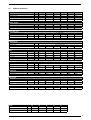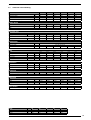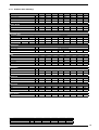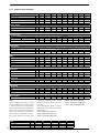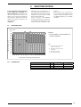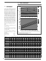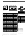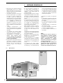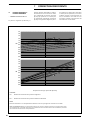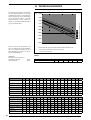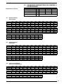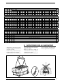
1
ENGLISH pag.2 Air/water chillers and heat pumps and condensing units with screw compressors ESPAÑOL pag.40 TECHNICAL MANUAL MANUAL TÉCNICO Enfriadoras y bombas de calor aire agua y motocondensadores con Compresor bi-tornillo High efficiency High efficiency in silenced version nsb Eficacia elevada Eficacia elevada en funcionamiento silencioso R134 134a a INSBTV. 0706. 6310811_01 che sostituisce il 6310811_00 del 06/09 INSTRUCTIONS FOR THE SELECTION Compliance declaration ........................................................................................................................................................................................................... 1 General standards ............................................................................................................................................................................................pag. 2 Description and choice of unit .....................................................................................................................................................................pag. 2.1 Models available .........................................................................................................................................................................pag. 2.2 Versions available ......................................................................................................................................................................pag. 2.2.1 Standard equipment .................................................................................................................................................................pag. 2.3 Configurator .................................................................................................................................................................................pag. 3 Description of components ...........................................................................................................................................................................pag. 3.1 Refrigerating circuit ..................................................................................................................................................................pag. 3.2 Frame and fans ...........................................................................................................................................................................pag. 3.3 Hydraulic components .............................................................................................................................................................pag. 3.4 Safety and control components ..........................................................................................................................................pag. 3.5 Electrical components .............................................................................................................................................................pag. 4 Accessories and table of possible combinations ................................................................................................................................pag. 5 Technical data 5.2 Versions (A) ..................................................................................................................................................................................pag. 5.3 Versions (E) ...................................................................................................................................................................................pag. 6 Selection criteria 6.1 Operating limits ...........................................................................................................................................................................pag. 6.2 Project data ..................................................................................................................................................................................pag. 7 Correction coefficients ...................................................................................................................................................................................pag. 8 Ethylene glycol solution ...................................................................................................................................................................................pag. 9 Pressure drops ..................................................................................................................................................................................................pag. 10 Desuperheaters.................................................................................................................................................................................................pag. 11 Total heat recovery ...........................................................................................................................................................................................pag. 12 Pumps ........................................................................................................................................................................................................... pag. 13 Sound data ........................................................................................................................................................................................................... pag. 13 Capacity control .................................................................................................................................................................................................pag. 14 Calibration of check and safety parameters .........................................................................................................................................pag. 15 Dimensions........................................................................................................................................................................................................... pag. 16 Weights and centres of mass .....................................................................................................................................................................pag. 17 Lifting points ........................................................................................................................................................................................................ pag. 18 Distribution of weights on the supports ..................................................................................................................................................pag. 19 Instructions for lifting ......................................................................................................................................................................................pag. 1 2 3 3 3 3 4 6 6 6 6 6 6 7 9 13 17 17 18 20 22 24 26 28 29 30 31 34 30 35 36 39 Dear Customer, Thank you for choosing AERMEC. It is the fruit of many years of experience and special design studies and has been made of the highest grade materials and with cutting edge technology. In addition, all our products bear the EC mark indicating that they meet the requirements of the European Machine Directive regarding safety. The standard of quality is permanently being monitored and AERMEC products are therefore a synonym for Safety, Quality and Reliability. The data may undergo modifications considered necessary for the improvement of the product, at any time and without the obligation for any notice thereof. Thank you again. AERMEC S.p.A AERMEC S.p.A. I-37040 Bevilacqua (VR) Italia – Via Roma, 44 Tel. (+39) 0442 633111 Telefax 0442 93730 – (+39) 0442 93566 www.aermec.com - [email protected] NSB MODEL: SERIAL NUMBER DECLARATION We declare under our own responsability that the above equipment described as follows: OF CONFORMITY Identificazione del prodotto AIR TO WATER CHILLER, NSB SERIE complies with following provisions: 1. Directive 97/23/EC and has been subjected (with reference to Attachment II of the said directive) to the following compliance evaluation procedure: module H with checks made via inspections by the appointed body CEC via Pisacane 46 Legnano (MI) - Itally, identity number 1131; 2. designed, manufactured and commercialized in compliance with the following technical specifications: 3. Bevilacqua - EN 378: Refrigerating system and heat pumps - Safety and environmental requirements; - EN 12735: Copper and copper alloys - Seamless, round copper tubes for air conditioning and refrigeration; - UNI 1285-68: calculation of metal tubes resistance to inside pressure; designed, manufactured and commercialized in compliance with the following EEC Directives: 98/37/CE: Machinery safety 2006/95/CE LVD 26/03/2007 Sales and Marketing Director Firma 1 1 • This manual, and the electrical layouts supplied with the unit, must be kept in a dry place for any future consultation, and for the lifespan of the machine. This manual has been drawn up with the aim of supporting the correct installation of the unit and providing all the indications for the correct use and maintenance of the device. Before proceeding with the installation, please read all the information in the manual carefully, as well as the procedures necessary for the correct installation and use of the unit. • Be careful to adhere to the instructions in this manual and observe the safety regulations currently in place. • The device must be installed in compliance with the local legislation currently in force in the country of destination. • Non-authorised tampering with the equipment, whether electrical or mechanical, will make THE WARRANTY VOID and exclude any liability on the part of the company. • Check the electrical characteristics shown on the registration plate (fig.1) before making the electrical connections. Read the instructions in the specific section about electrical connections. • If the unit needs to be repaired, in all 1.1 GENERAL STANDARDS cases contact a specialised AERMEC After Sales Service centre and only use OEM spare parts. • The manufacturer furthermore declines any liability for injury to persons or damage to things resulting from the failure to comply with the information in this manual. • Permitted uses: this series of chillers is suitable for producing cold water to use in hydronic systems designed for air conditioning. The units are not suitable for producing hot water for bathrooms. Any use other than that permitted, or outside the operating limits mentioned in this manual, is forbidden unless previously agreed with the company. The warranty does not include payment for damage due to wrong installation of the unit by the installer. • The warranty does not include payment for damage due to the improper use of the unit by the user. • The manufacturer is not to be considered liable for accidents to the user or the installer due to the incorrect installation or improper use of the unit. •The device must be installed in such a way that maintenance and/or repair operations can be carried out. The warranty of the device does not in any case cover costs incurred as a result of motorised ladders, scaffolding or any other lifting systems necessary to carry out the operations under warranty. The warranty is not valid when: • the services and repairs have been carried out by non-authorised personnel or companies; • the unit has been repaired or modified in the past with non-OEM spare parts; • the unit has not been adequately maintained; • the instructions described in this manual have not been followed; • non-authorised modifications have been made. N.B: The Manufacturer reserves the right at all times to make any modification for the improvement of its product, and is not obliged to add these modification to machines of previous manufacture that have already been delivered or are being built. The warranty conditions are anyway subject to the general sales conditions at the moment the contract is finalised. Technical plate Fig. 1 2 2 DESCRIPTION AND CHOICE OF UNIT Air-cooled liquid chillers with axial fans for outdoor installation (protection class IP24). They are fi tted with one or more chiller circuits. The evaporators are the pipe bundle type with dry expansion. The entire series can have up to three twoscrew compressors. The new NSB A series is distinguished by high effi ciency (EER) values thanks in part to the use of refrigerant R134a, too. that makes it possible to obtain effi ciencies that are considerably higher than the equivalent products that operate using R407C. This result is also the fruit of a careful study and scaling of all the internal components to get the best out of the characteristics of the R134a. refrigerant gas. Particular care has also been paid to the scaling of the exchangers, compressors and ventilators. All the units are tested and delivered complete with refrigerant load and oil, (it will be necessary only to make hydraulic and electrical connections on site). complete with partial heat recovery section. In this configuration a refrigerant / water heat exchanger on the gas delivery line and a condensation check is added to every chiller circuit unlike the base configuration. The heater is specially scaled to guarantee the recovery of the heat for the production of cold water for use in bathrooms or other. 2.1 2.2 MODELS AVAILABLE - “COOLIN ONLY” outside temperature 48°C. Acoustic compressor protection cover for quiet functioning. - “HEAT RECOVERY UNITS” (D) Desuperheater Unit, with air-cooling, (T) Total heat recovery Unit, complete with total heat recovery section. In this configuration a refrigerant / water heat exchanger on the gas delivery line as well as a three-way valve that provides for the cut in of the total heat recovery is added to every chiller circuit unlike the base configuration. The heater is specially scaled to guarantee the recovery of the heat for the production of cold water for use in bathrooms or other VERSION AVAILABLE configuration in several of the high efficiency versions (A), has mufflers on the pressing line, and a phase cut electronic device that allows a reduction in the number of fan rpms as the temperature conditions in the room change. - “VERSION Y” version Y :this is the version whereby refrigerated water under the standard value of +4 °C up to a minimum of -6 °C to be produced. Contact company headquarters for lower values.. NSB series chillers are available in 32 sizes. When the numerous options are combined, it is possible to configure each model in the NSB series in such a way as to meet the most varied of plant requirements. The following configurator shows the methods by which the commercial code of sixteen fields that make it up representing the options available is compiled. - "HIGH EFFICINCY" outside temperature 48°C. Acoustic compressor protection cover for quiet functioning. - “SILENCED HIGH EFFICINCY (E)” This 2.2.1 Standard equipment NSB A • Shell & tube • Pressure switch • Water inlet and outlet sensors (SIW - SUW) • Victaulic water connections WARNING WATER FILTER NOT SUPPLIED NSB E • Shell & tube • Pressure switch • Water inlet and outlet sensors (SIW - SUW) • Victaulic water connections • DCPX phase cut electronic device that allows a reduction in the number of fan rpms as the temperature conditions in the room change. WARNING WATER FILTER NOT SUPPLIED NSB D • Shell & tube • Pressure switch • Water inlet and outlet sensors (SIW - SUW) • Victaulic water connections • DCPX phase cut electronic device that allows a reduction in the number of fan rpms as the temperature conditions in the room change. • plate-type heat exchanger (desuperheater) 1 per circuit. WARNING WATER FILTER NOT SUPPLIED NSB T • Shell & tube • Pressure switch • Water inlet and outlet sensors (SIW - SUW) • Trhee way valve • Victaulic water connections • Heat recovery (Shell & tube) WARNING WATER FILTER NOT SUPPLIED • Total recovery (shell and tube exchanger) 1 per circuit NSB with pump (from PA to PK) • Shell & tube • Pressure switch • Water inlet and outlet sensors (SIW - SUW) • Victaulic water connections • Water filter not supplied • 1 or 2 pumps for the hydraulic circuit • 2 x 25 litre expansion tanks per circuit with gate valve cut-off. • Load group, 1 per circuit cut off by gate valve WARNING WATER FILTER NOT SUPPLIED 3 2.3 CONFIGURATOR 1,2,3 4,5,6,7 NSB 7203 (1) 8 ° 9 10 11 12 13 ° ° A ° ° ELECTRONIC VALVE 14 15,16 ° 00 field 15 - 16 The "ELECTRONIC EXPANSION VALVES" have a wide adjustment capacity to allow the compressors always to work in the best operational conditions possible (compatibly with the external environmental conditions). Therefore, in winter it is possible to work with very low condensation pressure, improving compressor performance and reducing the consumption of electricity. In our chillers the electronic valve allows a more efficient temperature adjustment, so much so to achieve, making the most of the evaporator surface, lower working temperatures being reached. Moreover, the system does not require calibration or future adjustments, as the electronics continually implements its control action on the basis of the parameters read by the transducers, maintaining optimal overheating values. As well as the data relative to the improved pressure conditions there are also improved compressor temperature conditions, maintaining unload temperatures lower than with use of the standard thermostatic valve. This determines an increase of compressor life and a reduction in the number of breakdowns. Therefore the advantages of using the electronic valve are: - Energy saving regarding plant consumption - Improved compressor work conditions (lower pressures, lower discharge temperatures), this determines less faults and therefore the reduction of maintenance costs. - Permanence of the performance through time - Less deterioration of compressor mechanical parts and lubrication oil - Repeatability of adjustment results and energy consumption through time. All of this confirms the commitment and respect that AERMEC has regarding energy saving and knowledgable and socially responsible use of the resources available. 4 Hydronic kit 00 Without pumping assembly PA pump A PB Pump A + reserve PC pump C PD Pump C + reserve PE pump E PF Pump E + reserve PG pump G PH Pump G + reserve PJ Pump J PK Pump K + reserve field 14 Power supply ° 3~400V-50Hz with fuses 2 3~230V-50Hz with fuses 4 3~230V-50Hz with thermomagnetic switches 5 3~500V-50Hz with fuses 8 3~400V-50Hz with thermomagnetic switches 9 3~500V-50Hz with thermomagnetic switches field 13 Evaporator ° According to PED standards C Condenser unit field 12 Coil ° R S V Aluminium Copper Tinned copper Painted aluminium copper field 11 Version A High efficiency E High efficiency in silenced version field 10 Heat recovery units Without recoverers ° D Desuperheater T Total recovery field 9 Model ° Cooling only field 8 Refrigerant: ° Standar mechanical and minimum water temperature Y produced down to -6 X R134a VT electronic (1) field 4 - 5 - 6 - 7 1251 - 1401 - 1601 - 1801 - 2101 - 2401 1402 - 1602 - 1802 - 2002 - 2202 - 2352 - 2502 - 2652 - 2802 - 3002 - 3202 - 3402 - 3602 3902 - 4202 - 4502 - 4802 5003 - 5203 - 5403 - 5703 - 6003 - 6303 6603 - 6903 - 7203 3 DESCRIPTION OF COMPONENTS Example NSB 2401 P2 KEY 1 Pumps 2 Hydraulic collector 3 Stand-by pumps 4 Unidirectional valve 5 Shut-off valve 6 Expansion vessels (2x25 litres), intercepted 7 Loading unit intercepted 8 Shell&tube 9 Rubinetto del liquido 10 Compressor bi-screw 11 Compressor area for soundproofing 12 Air exchange coils 13 Fans 14 Electric box closing panels 15 Suction safety valve (1 per circuit) 16 Filter drier (1 for circuit) 17 Thermostatic valve (1 for circuit) 5 3.1 REFRIGERANT CIRCUIT Compressors Semi hermetic high-efficiency screw compressors, with a cooling capacity regulation by means of continuous modulation from 40 to 100% (from 25 to 100% with electronic valve) and fitted with: - Thermal motor protection - Oil discharge temperature check - Electrical heating element for the heating of the oil casing with the compressor at a standstill - Reset button. Water side heat exchanger Shell & tube type exchanger of the direct expansion type suitably scaled to get high level performances. Steel housing with closed cell foam elastomer anticondensation mattress. The pipe bundle is made with copper tubes, with a special profile that allows high heat exchange together with efficient drainage. If so requested, the exchanger can be fitted with an anti-freeze electrical heating element, (accessory only to be fitted in the factory), that keeps the exchanger from lower outside temperatures down to -20°C, for the purpose of avoiding the formation of ice in stand-by mode. With the unit working protection is provided by the outlet water temperature probe. Filter drier With removable cartridge, it is able to hold back the impurities and any traces of humidity in the in cooling circuit. Sight glass For checking that the refrigerating gas load and any humidity in the refrigerating circuit. 3.2 FRAME AND FANS High pressure transducer t makes it possible to show the value of the compressor's delivery pressure (one per circuit) on the microprocessor card display. Placed on the high pressure side of the refrigeration circuit, it shuts down compressor operation in the case of abnormal operating pressure. Load-bearing structure Made of hot galvanised steel sheet of an adequate thickness, it is painted with polyester powders able to resist the atmospheric agents over time. Double high pressure switch (manual + tool) With variable calibration, placed on the high pressure side of the refrigeration circuit, it shuts down compressor operation in the case of abnormal operating pressure. Acoustic protection cover Standard on all the NSB versions, it consists of a compartment in very thick steel sheet and insulated entirely with soundproofing material. It permits the acoustic power emitted by the unit to be reduced and furthermore protects the compressors from the atmospheric agents. 3.3 HYDRAULIC CIRCUIT Circulation pump (only in versions with a pump) This, depending on the characteristics of the pump chosen, offers an effective pressure to over come the pressure drops in the system. NOTE When there is a second reserve pump, switching is manual by operating the selector switch inside the electrical panel Filling assembly (only in versions with a pump) This has a pressure gauge showing the pressure in the system. Liquid and pressing taps They allow the refrigerant to be cut off during extraordinary maintenance. 3.4 Solenoid valve the compressor's intake pressure (one per circuit) on the microprocessor card display. Placed on the low pressure side of the refrigeration circuit, it shuts down compressor operation in the case of abnormal operating pressure. Fan unit Screw type, statically and dynamically balanced. The electric fans are protected electrically with magnetothermal switches and mechanically with antiintrusion metal grilles in accordance with the CEI EN 294 60335-2-40 standard. Thermostatic valve The mechanical type valve with outside equaliser on the evaporator outlet mdoulates the gas flow to the evaporator dependent on the thermal load in such a way as to ensure the proper intake gas degree of overheating. Silencer Placed on the compressor delivery in version E contributes to deaden sound emission. 6 The valve closes when the compressor turns off, preventing the flow of refrigerant gas towards the evaporator. Expansion tanks (only in versions with a pump) SAFETY AND CHECKING COMPONENTS Differential pressure switch IP54 (installed as standard) Its job is to make sure that there is proper water circulation. If there is not, it shuts down the unit Low pressure transducer. It makes it possible to show the value of Refrigeration circuit safety valves (HP, LP) Calibrated to 22 bar HP - 16.5 LP, it cuts in relieving the overpressure in the case of abnormal operating pressures. 3.5 ELECTRICAL COMPONENTS Electrical panel Contains the power section and the management of the controls and safety devices. This conforms with standard CEI 60204-1, and electromagnetic compatibility directives EMC 89/336/ CEE and 92/31/CEE. Furthermore, all the cables are wired for immediate recognition of all the electrical components Door lock sectioner For safety the electrical panel can only be accessed by cutting of the power using the opening lever on the panel itself. This lever can be locked in place using one or more padlocks, during maintenance in order to prevent the machine being power ed up accidentally. Control keypad Provides full control functions. For a detailed description of the keypad refer to the user manual. - gate interlock system; - thermomagnetic compressor protection or fuses to be specified when ordered. - thermomagnetic fan protection; - thermomagnetic auxiliary protection; 3.6 ELECTRONIC REGULATION Electronic regulation on the NSB chillers consists of control cards for each compressor connected to each other in a network and a control panel with display. In the case of models with more than one compressor, the card that controls compressor 1 is the “master” card, while the others are "slaves". On each card, transducers, loads and alarms are connected to the compressor that commands while the general machine ones are connected only on the master card. Microprocessor - Remote on/off with external contact without power - Multilingual menu - Phase sequence control - Compressor/circuit fault display - Ammetric transformer - Fault cumulative block signall - Alarm history function - - Daily/weekly programming Inlet/outlet water temperature display Alarm display Full proportional regulation of the output water temperature Programmable timer function Function with double calibration point linked to the timer that can be programmed Fan regulation Inter faceability with the Modbus protocol (accessory) Pump control Compressor rotation control Analogue input from 4 to 20 mA Sonda temperatura aria esterna “Always Working” function. In the case of critical conditions (e.g. an ambient temperature that is too high) the machine does not stop but is able to regulate itself and provide the maximum power that can be generated in those conditions. 4 AER485P2 - card for MODBUS system Through this accessory it is possible to connect the unit with BMS supervision systems with electrical standard RS 485 and MODBUS type protocol. AVX - Antivibration support Supporti anti-vibranti a molla. Select the AVX model using the compatibility table. GP - Protection grilles Protect the external coil from chance knocks and prevent access to the area underneath where compressors and the cooling circuit are housed. Each kit has two grilles. (to be installed in the factory) PRV - Remote control panel This allows the refrigerator command operations to be given from a distance. KRS - Exchanger electrical heating elements for outside temperatures down to -20 °C (to be installed in the factory) - Self adapting operating differential “Switching Histeresys” to ensure the correct compressor functioning at all times even in plants with a low water content or insufficient flow rates. This system reduces the compressor wear -T h e A F F P “A n t i F r e e z i n g F a n Protection” system that turns on the fans periodically when the external temperatures are very low - The PDC “Pull Down Control” system to prevent the activation of the power steps when the water temperature is approaching the set point quickly. It optimises the operation of the machine both when running normally or when there are load variations, thereby assuring top machine efficiency in all situations ACCESSORIES ROMEO (Remote Overwatching Modem Enabling Operation) is a device that enables a remote control of a chiller from an ordinary WAP mobile phone. Furthermore it allows to send alarm or pre-alarm SMS messages up to 3 GSM mobile phones which may not be equipped with WAP. The set includes the AER485. Added to the is kit must be the AER485P2 accessory. RIF: Current rephaser. Parallel connection with the motor makes the reduction of input current possible - - - that allows to reduce vibrations even more. Anti-vibration mounts in AV rubber selected for the compressors in order to reduce their vibrations, in a way to prevent damage to the pipes and the use of flexible joints. Insulation of the largest pipes in order to reduce the typical noise of the gas. Insulation of the most critical points. Silenced fan motors. NOTE This can only be installed when the machine is being made and must therefore be specified when the order is placed. (to be installed in the factory) NOTE This can only be installed when the machine is being made and must therefore be specified when the order is placed. (to be installed in the factory) AK - Acustic Kit (only for version E) This accessory allows to reduce noise further by means of: - Compressor cover optimised using high density material without lead 7 MOD. 1251 1401 1601 1801 2101 2401 1402 1602 1802 2002 2202 2352 2502 2652 2802 3002 3202 3402 3602 3902 4202 4502 4802 5003 5203 5403 5703 6003 6303 6603 6903 7203 ROMEO • • • • • • • • • • • • • • • • • • • • • • • • • • • • • • • • KRS 4 5 5 5 5 5 5 5 5 5 5 5 5 5 5 5+5 5+5 5+5 5+5 5+5 5+5 5+5 5+5 5+5+5 5+5+5 5+5+5 5+5+5 5+5+5 5+5+5 5+5+5 5+5+5 5+5+5 AER485P2 PRV • • • • • • • • • • • • • • • • • • • • • • • • • • • • • • • • • • • • • • • • • • • • • • • • • • • • • • • • • • • • • • • • AK Vers. E Vers. E Vers. E Vers. E Vers. E Vers. E Vers. E Vers. E Vers. E Vers. E Vers. E Vers. E Vers. E Vers. E Vers. E Vers. E Vers. E Vers. E Vers. E Vers. E Vers. E Vers. E Vers. E Vers. E Vers. E Vers. E Vers. E Vers. E Vers. E Vers. E Vers. E Vers. E 5 5.1 NOMINAL REFERENCE CONDITIONS KEY (1) FLA (2) LRA (3) EEEC 12 °C 7 °C 35 °C 5°C 15 °C 2 °C 0% = Max. Current absorbed at full load = Peak current at full load = With electronic thermstatic valve the minimum step is 25% = EUROVENT Energy Efficiency Class Sound Power Aermec determines the value of sound power on the basis of measurements performed in compliance with regulation 9614, in respect with that requested by Eurovent certification. (1) Sound Pressure Sound pressure in free field on a reflective sur- 8 300M 300M 300M 400M 500M 500M 300B 300B 400B 500B 500B 500B 500B 500B 500B 300M+300M 300M+300M 300M+400M 400M+400M 400M+500M 400M+500M 500M+500M 500M+500M 300M +300M+400M 300M+400M+400M 400M+400M+400M 400M+400M+500M 400M+400M+500M 400M+500M+500M 400M+500M+500M 500M+500M+500M 500M+500M+500M DCPX 36 36 36 45 45 45 29 29 29 30 30 30 30 30 30 30 30 46 46 46 46 46 46 1x(30) e 1x(47) 1x(46) e 1x(47) 1x(46) e 1x(47) 1x(46) e 1x(47) 1x(46) e 1x(47) 1x(46) e 1x(47) 1x(46) e 1x(47) 1x(46) e 1x(47) 1x(46) e 1x(47) RIF. AVX 301 301 301 301 371 411 161 x 2 161 x 2 201 x 2 201 + 241 241 x 2 241 + 301 301 x 2 301 x 2 301 x 2 301 x 2 301 x 2 301 x 2 301 x 2 301 + 371 301 + 411 371 + 411 411 x 2 301 x 3 301 x 3 301 x 3 301x2+371 301x2+411 301+371+411 301+411x2 371+411x2 411x3 A E AD/ED AT/ET 502 502 502 506 510 510 503 503 504 511 511 511 511 511 511 509 509 513 516 519 519 521 521 517 515 522 526 526 528 528 531 531 502 502 502 506 510 510 503 503 504 511 511 511 511 511 511 509 509 513 516 519 519 521 521 517 515 522 526 526 528 528 531 531 502 502 502 506 510 510 503 503 504 511 511 511 511 511 511 509 509 513 516 519 519 521 521 517 515 522 526 526 528 528 531 531 503 503 503 506 510 510 501 501 504 511 511 511 511 511 511 509 507 508 516 520 520 521 521 517 515 522 526 526 529 529 531 531 TECHNICAL DATA face (factor of directionality Q=2), at 10 metres from the external surface of the unit, using the parallel expansion method (box-method, ISO 3744) The technical data is calculated as follows Cooling mode - Temperature water inlet - Temperature of processed water - Ambient air temperature - ∆t freecooling mode - temperatura acqua ritorno - Ambient air temperature - glycol GP NOTE - The noise data refer to configuration without pump. E.S.E.E.R. There is a growing awareness in Europe as well that attention needs to be paid to the electricity consumed by air conditioning machines. For many years now in the United States talk has not just been about efficiency in the plan conditions, but an assessment index is used that takes account of the marginal operation of the unit under plan conditions and the greater use with partial loads with external air that is less than that planned and in conditions of compressor capacity control. In Europe the proposed EECCAC (Energy Efficiency and Certification of Central Air Conditioner) has been adopted, the ESEER (European Seasonal Energy Efficiency Ratio), that has the purpose of being able to compare the chillers with each other. After estimating the total energy required by the system during summer management (kW/h), the seasonal electrical energy consumption can be deduced with this formula: Input energy = Required energy Efficiency index The actual energy calculation can be obtained, more accurately, by considering: 1. The load profile with external temperature 2. The climatic profile 3. The total number of hours With this data, every consultant or designer will be able to his or her evaluations. ESEER = (3xEER100%+33xEER75%+41xEER50%+23xEER25%) / 100 Evaporator outlet water ∆T at full load Load External air temperature 100% 35°C 75% 30°C 50% 25°C 7 °C 5 °C 25% 20°C 5.2 TECNICHAL VERSION (A) Cooling capacity: Total input power Evaporator water flow rate Evaporator pressure drop ENERGY INDICES EER ESEER CEEE 1251 1401 1601 1801 2101 2401 kW kW l/h kPa 276 88 47470 49 314 97 54010 32 347 104 59680 38 420 134 72240 45 466 150 80150 32 533 165 91680 41 W/W 3.14 4.22 A 3.24 4.24 A 3.34 4.30 A 3.13 4.24 A 3.11 4.20 A 3.23 4.28 A 242 154 332 304 172 454 304 181 359 408 256 616 458 279 680 W/W ELECTRICAL DATA Fuel feed FLA (1) Maximum current LRA (2) A MAX A Chiller A Corr. spunto A COMPRESSORS Type Capacity check % Number n° FANS Type Quantity Air flow rate Input power Input current 3~400V-50Hz 355 222 489 Two-screw 40 - 100 (continue) 1 1 1 1 1 1 Axial 6 m3/h 110.000 kW 8.4 A 18 Axial 6 106.000 8.4 18 Axial 6 106.000 8.4 18 Axial 8 136.000 11.2 24 Axial 10 180.000 14 30 Axial EVAPORATOR Type Quantity Water connection n° ø 1 1 1 1 Victaulic 4” Victaulic 5” Shell&tube 1 Victaulic 5” Victaulic 5” Victaulic 6” Victaulic 6” SOUND DATA Sound pressure (1) Sound power dB(A) 62.0 dB(A) 94.0 63.0 95.0 65.0 97.0 65.0 97.0 66.0 98.0 66.0 98.0 DIMENSIONS Heigh Width Length mm mm mm 2.450 2.200 3.780 2.450 2.200 3.780 2.450 2.200 3.780 2.450 2.200 4.770 2.450 2.200 5.750 2.450 2.200 5.750 kg. 3050 3230 3250 4330 4920 5150 FC 5,5 7,5 117 FE 7,5 10 121 FG 9,2 12,5 140 FJ 11 15 148 n° 1 10 174.000 14 30 EMPTY WEIGHT PUMP Input power Input current Weight kW A kg PA 4 5,5 109 9 5.2.1 TECNICHAL VERSION (A) Cooling capacity: Total input power Evaporator water flow rate Evaporator pressure drop kW kW l/h kPa ENERGY INDICES EER ESEER CEEE ELECTRICAL DATA Fuel feed FLA (1) Maximum current LRA (2) 1402 1602 1802 2002 2202 2352 2502 2652 2802 304 97 52290 31 345 109 59340 36 397 127 68280 46 450 144 77400 51 495 157 85140 36 519 166 89270 40 543 173 93400 43 577 182 99240 34 612 197 105260 38 4.20 A 3.17 4.30 A 3.13 4.20 A 3.13 4.23 A 3.15 4.24 A 3.13 3.71 A 3.14 4.25 A 3.17 4.25 A 3.11 4.21 A 273 171 226 298 190 266 345 215 308 391 248 352 3~400V-50Hz 432 454 274 288 366 413 477 301 429 508 320 456 538 339 458 W/W 3.13 A A MAX A chiller Corr. spunto A COMPRESSORS Type Capacity check % Number n° FANS Type Quantity Air flow rate Input power Input current n° 6 m3/h 106000 two-screw 40 - 100 (continue) 2 2 2 2 2 2 2 2 2 Axial Axial 6 Axial 8 Axial 10 Axial 10 Axial 10 Axial 10 Axial 10 Axial 10 106000 144000 187500 180000 176500 173000 173000 173000 8.4 18 8.4 18 11.2 24 14 30 14 30 14 30 14 30 14 30 14 30 1 V/5” 1 V/5” 1 V/5” 1 V/5” 1 V/6” 1 V/6” 1 V/6” 1 V/6” 1 V/6” 64.0 96.0 65.0 97.0 65.0 97.0 66.0 98.0 66.0 98.0 65.0 98.0 66.0 98.0 66.0 99.0 66.0 99.0 mm 2450 2200 3780 2450 2200 3780 2450 2200 4770 2450 2200 5750 2450 2200 5750 2450 2200 5750 2450 2200 5750 2450 2200 5750 2450 2200 5750 kg. 3420 3560 3900 4700 5270 5390 5500 5510 5520 kW A EVAPORATOR Type Shlell&tube Quantity n° Water connection ø SOUND DATA Sound pressure (1) Sound power dB(A) dB(A) DIMENSIONS Heigh Width Length mm mm EMPTY WEIGHT PUMP Input power Input current Weight 10 kW A kg PA 4 5,5 109 PC 5,5 7,5 117 PE 7,5 10 121 PG 9,2 12,5 140 PJ 11 15 148 5.2.2 TECNICHAL VERSION (A) Cooling capacity: Total input power Evaporator water flow rate Evaporator pressure drop kW kW l/h kPa ENERGY INDICES EER ESEER CEEE ELECTRICAL DATA Fuel feed FLA (1) Maximum current LRA (2) 3002 3202 3402 3602 3902 4202 4502 4802 661 201 113690 35 695 208 119540 38 767 238 131920 44 839 268 144310 45 885 284 152220 40 953 298 163920 45 999 314 171830 37 1066 329 183350 41 3.34 4.3 A 3.22 4.26 A 3.13 4.19 A 3.12 4.18 A 3.20 4.24 A 3.18 4.17 A 3.24 4.17 A 608 362 464 659 403 594 3~400V-50Hz 710 763 444 478 618 745 813 501 847 865 535 847 916 558 850 W/W 3.29 4.28 W/W A A A MAX A chiller Corr. spunto A 576 353 464 COMPRESSORS Type Capacity check % Number n° FANS Type Quantity Air flow rate Input power Input current n° 12 m3/h 212000 Two-screw 40 - 100 (continua) 2 2 2 2 2 2 2 2 Axial Axial 12 Axial 14 Axial 16 Axial 18 Axial 18 Axial 20 Axial 20 212000 242000 272000 316000 310000 354000 348000 17 36 17 36 20 42 22 48 25 54 25 54 28 60 28 60 2 V/5” 2 V/5” 2 V/5” 2 V/5” 2 V/5” - 6” 2 V/5” - 6” 2 V/6” 2 V/6” 67.0 99.0 67.0 100.0 67.0 100.0 67.0 100.0 68.0 101.0 68.0 101.0 68.0 101.0 68.0 101.0 mm 2450 2200 7160 2450 2200 7160 2450 2200 8150 2450 2200 9140 2450 2200 10120 2450 2200 10120 2450 2200 11100 2450 2200 11100 kg 6450 6520 7540 8610 9180 9410 9820 10200 kW A EVAPORATOR Type Shell&tube Quantity n° Water connection ø SOUND DATA Sound pressure (1) Sound power dB(A) dB(A) DIMENSIONS Heigh Width Length mm mm EMPTY WEIGHT PUMP Input power Input current Weight kW A kg PA 4 5,5 109 PC 5,5 7,5 117 PE 7,5 10 121 PG 9,2 12,5 140 PJ 11 15 148 11 5.2.3 TECNICHAL VERSION (A) Cooling capacity: Total input power Evaporator water flow rate Evaporator pressure drop kW kW ENERGY INDICES EER ESEER CEE ELECTRICAL DATA Fuel feed FLA (1) Maximum current LRA (2) 5003 5203 5403 5703 6003 6303 6603 6903 7203 1114 342 1186 372 1259 401 1305 417 1372 432 1419 448 1486 463 1532 479 1600 494 l/h 191610 203990 216550 224460 235980 244070 255590 263500 275200 kPa 44 44 45 40 45 40 45 37 41 3.19 4.26 A 3.14 4.2 A 3.13 4.15 A 3.18 4.28 A 3.17 4.25 A 3.21 4.28 A 3.20 4.29 A 3.24 4.28 A 1014 625 723 1066 666 747 1118 700 874 1271 780 976 1323 814 1017 1373 837 1020 W/W 3.26 4.25 W/W A A MAX A A peck cur. A 963 584 699 COMPRESSORS Type Capacity check % Number n° FANS Type Quantity Air flow rate Input power Input current n° 20 m3/h 348000 kW A 3~400V-50Hz 1168 1221 723 757 938 976 bi-vite 40 - 100 (continua) 3 3 3 3 3 3 3 3 3 Axial Axial 22 Axial 24 Axial 26 Axial 26 Axial 28 Axial 28 Axial 30 Axial 30 378000 408000 452000 446000 490000 484000 528000 522000 28 60 31 66 34 72 36 78 36 78 39 84 39 84 42 90 42 90 3 V/5” 3 V/5” 3 V/5” - 6” 3 V/5” - 6” 3 V/5” - 6” 3 V/6” 3 V/6” EVAPORATOR Type Shell&tube Quantity n° Water connection ø 3 V/5” 3 V/5” - 6” SOUND DATA Sound pressure (1) dB(A) 69.0 69.0 69.0 69.0 69.0 69.0 69.0 70.0 70.0 Sound power dB(A) 102.0 102.0 102.0 102.0 102.0 102.0 103.0 103.0 103.0 DIMENSIONS Heigh Width mm mm 2450 2200 2450 2200 2450 2200 2450 2200 2450 2200 2450 2200 2450 2200 2450 2200 2450 2200 Length mm 11530 12520 13510 14490 14490 15470 15470 16450 16450 kg 11160 12320 13540 13530 13760 14330 14560 14970 15350 EMPTY WEIGHT PUMP Input power Input current Weight 12 kW A kg FA 4 5,5 109 FC 5,5 7,5 117 FE 7,5 10 121 FG 9,2 12,5 140 FJ 11 15 148 5.3 TECNICHAL DATA VERSION (E) Cooling capacity: Total input power Evaporator water flow rate Evaporator pressure drop 1401 1601 1801 2101 2401 291 101 50050 27 330 109 56760 33 391 140 67250 41 432 155 74300 28 497 165 85480 36 2.80 3.07 C 2.88 3.08 B 3.03 3.13 B 2.79 3.08 C 2.79 3.05 C 2.89 3.11 C 230 152 321 293 170 443 293 182 348 389 255 597 439 283 661 1 1 two-screw 40 - 100 (continue) 1 1 1 1 Axial 6 70000 3.3 6.6 Axial 6 74000 3.6 6.6 Axial 6 81500 3.6 6.6 Axial 10 113000 7 11 118000 7 11 1 V 4” 1 V 4” 1 V 5” Shell&tube 1 V 5” 1 V 5” 1 V 6” 54.0 86.0 55.0 87.0 57.0 89.0 57.0 89.0 58.0 90.0 58.0 90.0 mm 2.450 2.200 3.780 2.450 2.200 3.780 2.450 2.200 3.780 2.450 2.200 4.770 2.450 2.200 5.750 2.450 2.200 5.750 kg. 3050 3230 3250 4330 4920 5150 PG 9,2 12,5 140 PJ 11 15 148 kW l/h kPa ENERGY INDICES EER ESEER CEEE ELECTRICAL DATA Fuel feed FLA (1) Maximum current LRA (2) 1251 252 90 43340 41 kW W/W A MAX A A Peack cur. COMPRESSORS Type Capacity check Number A % n° FANS Type Quantity Air flow rate Input power Input current n° m3/h kW A EVAPORATOR Type Quantity Water connection n° ø SOUND DATA Sound pressure (1) Sound power dB(A) dB(A) DIMENSIONS Heigh Width Length mm mm 3~400V-50Hz 340 225 474 Axial 8 94000 5.2 8.8 Axial 10 EMPTY WEIGHT PUMP Input power Input current Weight kW A kg PA 4 5,5 109 PC 5,5 7,5 117 PE 7,5 10 121 13 5.3.1 TECNICHAL DATA VERSION (E) Cooling capacity Total input power Water flow rate Pressure drops evaporator kW kW l/h kPa ENERGY INDICES EER ESEER CEEE W/W ELECTRICAL DATA Power supply FLA (1) MAX Total current power LRA (2) Peck Cur. 1402 1602 1802 2002 2202 2352 2502 2652 2802 273 101 46960 25 314 115 54010 30 364 130 62610 40 410 150 70520 42 453 161 77920 30 478 171 82220 34 503 181 86520 37 539 192 92710 30 574 207 98730 33 2.56 3.08 C 2.43 3.1 C 2.37 3.09 C 2.37 3.11 C 2.37 3.11 C 2.46 3.12 C 2.45 3.1 C 2.44 3.12 C 2.42 3.09 C 262 170 214 289 194 256 330 214 292 372 247 332 3~400V-50Hz 412 435 277 290 346 394 458 303 410 489 320 437 519 344 439 2 2 2 Axial 10 Axial 10 Axial 10 A A A A COMPRESSOR Type Capacity check Quantity two-screw 40 - 100 (continua) 2 2 % n° FANS Type Quantity Air flow rate Input power Input current n° m3/h 2 2 2 2 Axial 6 Axial 6 Axial 8 Axial 10 Axial 10 Axial 10 74000 77000 96000 124500 120000 123000 126000 130000 136000 3 6.3 4.8 8.4 4 8.4 7 10.5 8 11 7 11 6.5 11 6.5 11 6.5 11 1 V/5” 1 V/5” 1 V/5” 1 V/5” 1 V/6” 1 V/6” 1 V/6” 1 V/6” 1 V/6” 56.0 88.0 57.0 89.0 57.0 89.0 58.0 90.0 58.0 90.0 58.0 90.0 58.0 90.0 58.0 91.0 59.0 91.0 mm 2450 2200 3780 2450 2200 3780 2450 2200 4770 2450 2200 5750 2450 2200 5750 2450 2200 5750 2450 2200 5750 2450 2200 5750 2450 2200 5750 kg. 3420 3560 3900 4700 5270 5390 5500 5510 5520 kW A EVAPORATOR Type Shell&tube Quantity n° Water connection ø SOUND DATA Sound pressure (1) Sound power dB(A) dB(A) DIMENSIONS Heigh Width Length mm mm EMPTY WEIGHT PUMP Input power Input current Weight 14 kW A kg PA 4 5,5 109 PC 5,5 7,5 117 PE 7,5 10 121 PG 9,2 12,5 140 PJ 11 15 148 5.3.2 TECNICHAL DATA VERSION (E) Cooling capacity Total input power Water flow rate Pressure drops evaporator 3202 3402 3602 3902 4202 4502 4802 622 210 106980 31 660 218 113520 34 721 249 124010 40 782 280 134500 40 822 295 141380 34 888 312 152740 39 928 327 159620 32 994 344 170970 36 2.96 3.15 B 3.03 3.16 B 2.90 3.13 C 2.79 3.08 C 2.79 3.08 C 2.85 3.12 C 2.84 3.07 C 2.89 3.07 C A 553 352 585 364 680 407 3~400V-50Hz 680 729 450 480 779 508 827 538 878 566 A 441 441 567 588 809 809 812 kW l/h kPa ENERGY INDICES EER ESEER CEEE W/W ELECTRICAL DATA Power supply FLA (1) MAX Total current power LRA (2) 3002 kW A A Peck Cur. COMPRESSOR Type Capacity check Quantity Two-screw 40 - 100 (continue) % n° FANS Type Quantity Air flow rate Input power Input current n° m3/h 711 2 2 2 2 2 2 2 2 Axial 12 Axial 12 Axial 14 Axial 16 Axial 18 Axial 18 Axial 20 Axial 20 155500 163000 175500 188000 207000 212000 231000 236000 7 13 7 13 9 15 10 18 12 20 12 20 14 22 14 22 2 V/5” 2 V/5” 2 V/5” 2 V/5” 2 V/5” - 6” 2 V/5” - 6” 2 V/6” 2 V/6” 58.0 91.0 59.0 92.0 59.0 92.0 60.0 92.0 60.0 93.0 60.0 93.0 60.0 93.0 60.0 93.0 mm 2450 2200 7160 2450 2200 7160 2450 2200 8150 2450 2200 9140 2450 2200 10120 2450 2200 10120 2450 2200 11100 2450 2200 11100 kg. 6450 6520 7540 8610 9180 9410 9820 10200 kW A EVAPORATOR Type Shell&tube Quantity n° Water connection ø SOUND DATA Sound pressure (1) Sound power dB(A) dB(A) DIMENSIONS Heigh Width Length mm mm EMPTY WEIGHT PUMP Input power Input current Weight kW A kg PA 4 5,5 109 PC 5,5 7,5 117 PE 7,5 10 121 PG 9,2 12,5 140 PJ 11 15 148 15 5.3.3 TECNICHAL DATA VERSION (E) Cooling capacity kW Total input power Water flow rate Pressure drops evaporator kW ENERGY INDICES EER ESEER CEEE ELECTRICAL DATA Power supply FLA (1) MAX Total current power LRA (2) peak current 5003 5203 5403 5703 6003 6303 6603 6903 7203 1051 358 1112 389 1172 421 1213 435 1278 452 1319 467 1384 484 1425 499 1490 516 l/h 180770 191260 201580 208640 219820 226870 238050 245100 256280 kPa 40 39 39 34 39 35 39 32 36 W/W 2.94 3.09 B 2.86 3.1 C 2.78 3.06 C 2.79 3.02 C 2.83 3.12 C 2.82 3.1 C 2.86 3.12 C 2.86 3.12 C 2.89 3.12 C 925 589 661 973 632 681 1020 674 701 1069 705 825 3~400V-50Hz 1119 1167 733 763 889 923 1218 791 923 1266 821 960 1316 849 963 A A A A COMPRESSOR Type Capacity check Quantity bi-vite 40 - 100 (continua) % n° FANS Type Quantity Air flow rate Input power Input current n° m3/h 3 3 3 3 3 3 3 3 3 Axial 20 Axial 22 Axial 24 Axial 26 Axial 26 Axial 28 Axial 28 Axial 30 Axial 30 257000 269500 282000 301000 306000 325000 330000 349000 354000 12 22 14 24 16 26 17 29 17 29 19 31 19 31 21 33 21 33 3 V/5” 3 V/5” 3 V/5” 3 V/5” - 6” 3 V/5” - 6” 3 V/5” - 6” 3 V/5” - 6” 3 V/6” 3 V/6” 61.0 94.0 61.0 94.0 61.0 94.0 61.0 94.0 61.0 94.0 61.0 94.0 61.0 95.0 61.0 95.0 62.0 95.0 mm 2450 2200 11530 2450 2200 12520 2450 2200 13510 2450 2200 14490 2450 2200 14490 2450 2200 15470 2450 2200 15470 2450 2200 16450 2450 2200 16450 kg. 11160 12320 13540 13530 13760 14330 14560 14970 15350 kW A EVAPORATOR Type Shell&tube Quantity n° Water connection ø SOUND DATA Sound pressure (1) Sound power dB(A) dB(A) DIMENSIONS Heigh Width Length mm mm EMPTY WEIGHT le it will be positioned under the heat exchanger finned coil on the compressor side. So for weights and centres of gravity and relative lifting points refer to their compositions 5703 = NSB 3602+NSB 2101 6003 =NSB 3602+NSB 2401 6303 = NSB 3902+NSB 2401 NOTA (1)The models from 5703 to 7203 are sent separately, 1 double module, 1 single-module. In the compositions shown hereunder, we only indicate the dimensions of the bases without the 400 mm of overhang of the electrical box that will be assembled in the double module, while in the single modu- PUMP Input power Input current Weight 16 kW A kg FA 4 5,5 109 FC 5,5 7,5 117 FE 7,5 10 121 FG 9,2 12,5 140 6603 = NSB 4202+NSB 2401 6903 = NSB 4502 +NSB 2401 7203 = NSB 4802+NSB 2401 FJ 11 15 148 6 In their standard set-up, the equipment is not suitable for installation in a saline environment. The maximum and minimum water flow rate values are shown on the curves of the pressure drop diagrams. Reference should be made to the diagram below for the operation limits. WARNING: 6.1 SELECTION CRITERIA - Operation with a temperature of the water produced below 4°C is only allowed for versions specifically adapted to produce water cooled down to -6°C (version YA) - Please contact the AERMEC technical sales office in the event it is necessary to operate the machine outside the limits indicated in the diagram. If the machine is to be placed in a particularly windy position, wind breaks must be provided to avoid the DCPX operating in an unstable condition OPERATING LIMITS "Cold mode" 50 48 40 35 48 48 44 1 VERSION • HIGH EFFICIENCY A/HIGH EFFICIENCY IN SILENCED VERSION E 3 External air temp. d.b. °C 30 25 20 15 2 10 4 KEY 1 Operation with glycol water 5 0 2 -5 3 -10 4 only for versions YA Operation with glycol water and DCPX Standard operation Operation with DCPX -6 -4 -2 0 1 2 3 4 5 6 7 8 9 10 11 12 13 14 15 Temperature of water produced (∆t=5°C) 6.2 DESIGNE DATA Max pressure allowable Max temp. allowable Min. temp. allowable bar °C °C High pressure side 22 120 -10 Low pressure side 16,5 55 -10 17 CORRECTION COEFFICIENT 7 7.1 and the input electrical capacity in conditions other than rated conditions are obtained by multiplying the rated values (Pf, Pa) by the respective corrective coefficients (Cf, Ca). The diagrams on the following page COOLING CAPACITY AND IMPUT POWER - VERSION "HIGH EFFICIENCY” The refrigerating capacity yielded (page 20) make it possible to obtain correction coefficients to be used for the chillers in cooling operation mode; next each curve the external air temperature to which it refers 1,50 1,40 1,30 48 1,20 40 45 1,10 Ca 35 30 1,00 25 0,90 20 0,80 0,70 0,60 0,50 0,40 -6 -5 -4 -3 -2 -1 0 1 2 3 4 5 6 7 8 9 10 11 12 13 14 15 1,50 16 20 25 1,40 30 1,30 35 1,20 40 1,10 Cf 1,00 45 0,90 48 0,80 0,70 0,60 0,50 0,40 -6 -5 -4 -3 -2 -1 0 1 2 3 4 5 6 7 Produced water temperature t∆5°C KEY: Cf = Cooling capacity correction coefficient Ca = Input power correction coefficient NOTA: FOR THE Y VERSIONS with temperatures below 4 °C contact company headquarters FOR ∆T DIFFERENT FROM 5°C The table 7.4 below is used to get the correction factors of both the cooling capacity and the input power and those of exchanger dirtying 18 8 9 10 11 12 13 14 15 16 7.2 COOLING CAPACITY AND IMPUT POWER The refrigerating capacity yielded and the input electrical capacity in conditions other than rated conditions are obtained by multiplying the rated values (Pf, Pa) by the respective corrective coefficients (Cf, Ca). - VERSION "HIGH EFFICIENCY SILENCED MODE” The diagrams on the following page (page 20) make it possible to obtain correction coefficients to be used for the chillers in cooling operation mode; next each curve the external air temperature to which it refers 1,50 1,40 1,30 48 1,20 45 40 1,10 Ca 35 1,00 30 25 0,90 20 0,80 0,70 0,60 0,50 0,40 -6 -5 -4 -3 -2 -1 0 1 2 3 4 5 6 7 8 9 10 11 12 13 14 15 16 1,50 20 25 30 35 40 1,40 1,30 1,20 1,10 Cf 1,00 45 0,90 48 0,80 0,70 0,60 0,50 0,40 -6 -5 -4 -3 -2 -1 0 1 2 3 4 5 6 7 8 9 10 11 12 13 14 15 16 Produced water temperature t∆5°C 7.3 FOR ∆T DIFFERENT TO NOMINAL FOR ∆T OTHER THAN 5°C For the evaporator, the Tav.7.3.1 is used to obtain the correction factors of the cooling and input capacities. To take into account the dirtying of the exchangers, the relative dirtying factors are used 7.4 FOULING FACTORS The performances provided in the table refers to conditions where the pipes are clean with an fouling factor = 1. For different fouling factor values multiply the data in the performance tables by the coefficients shown. 7.3.1 Correction factors for ∆t different from the rated value Chiller Cooling capacity correction factors Total imput power corrections factors 7.4.1 3 0,99 0,99 5 1 1 8 1,02 1,01 10 1,03 1,02 Fouling factors Cooling capacity correction factors Total imput power corrections factors [K*m2]/[W] 0,00005 1 1 0,0001 0.98 0,98 0,0002 0.94 0,95 19 ETHYLENE GLYCOL SOLUTION 8 The cooling capacity and input power correction factors make allowance for the presence of glycol and the different evaporation temperature. The correction factors of the water flow rate and the pressure drops are applied directly to the data obtained for operation without glycols. The correction factor of the water flow rate is calculated so as to maintain the same ∆t that would be used in the absence of glycols. - The correction factor of the pressure drop already takes into account the different capacity deriving from the application of the water flow rate correction factor. - The correction factors of the water flow rate and the pressure drops are applied directly to the data obtained for operation without glycols. - The correction factors of the cooling and input capacities take into account the presence of glycols. - The correction factors of the water flow rate and the pressure drops are applied directly to the data obtained for operation without glycols. - The correction factor of the water flow rate is calculated so as to maintain the same Dt that would be used in the absence of glycols. - The correction factor of the pressure drop already takes into account the different capacity deriving from the application of the water flow rate correction factor. By using the diagram opposite it possible to establish the percentage of glycol necessary; this percentage can be calculated taking into account one of the following factors: On the basis of the fluid considered (water or air), it will be necessary to enter the graph from the right or left side, from the intersection of the - If you want t o calculat e t he percentage of glycol on the basis of the outside air temperature, you must enter from the left-hand axis and, once you have intersected the curve, trace a vertical line which, in turn, will intercept all the other curves; the points obtained from the upper curves represent =[>;h=Û¨Z© KEY: FcGPf =[>;h=Û¨[© FcGPa =[>;h=Û¨Y© ~ ~ =[>;h=Û¨\© ~ =[>;h=Û¨]© FcGDpF (a) ~ ~ FcGDpF (b) ~ =[>H= ~ =[>HÛ¨G\:© ~~ FcGDpF (c) =[>G^Û¨G\:© ~ FcGDpF (d) =[>GY =[>G^ ¤ ¤ ¤~ ¤~ ¤ ¤ ¤ ¤ ¤ ~ ~ K]eh]jYlmjYÛ Y[imYÛhjg\gllYÛµ: =Yllgj]Û[gjj]llang HOW TO READ THE GLYCOL CURVES NOTE To make it easier to read the graph, an example is given on the next page. ~ K]eh]jYlmjYÛYjaYÛ]kl]jfYÛµ: 8.1 The cur ves shown in the figure summarise a notable quantity of data, each of which is represented by a specific curve. In order to use these curves correctly, it is necessary to make some initial considerations: ~ 20 outside air temperature or processed water temperature straight lines and the relative curves, a point is obtained through which the vertical line that will identify both the percentage of glycol and the relative correction coefficients will have to pass. FcGDpF (e) FcGQF FcGQC Correction factor of the cooling capacity Correction factor of the input power Correction factor of the pressure drops (evaporat or) (average temp. = -3.5°C) Correction factor of the pressure drops (average temp. = 0.5°C) Correction factor of the pressure drops (average temp. = 5.5°C) Correction factor of the pressure drops (average temp. = 9.5°C) Correction factor of the pressure drops (average temp. = 47.5°C) Correction factor of the outputs (evaporator) (average temp. = 9.5°C) Correction factor of the outputs (condenser) (average temp. = 47.5°C) NOTE Although the graph reaches outside air temperatures of 40°C, it is necessary to maintain the machine's operating limits as reference. the coefficients for the correction of the cooling capacity and input power, for the flow rates and the pressure drops (remember that these coefficients must anyway be multiplied by the nominal value of the sizes examined); the lower axis advises the percentage of glycol necessary on the basis of the outside air temperature considered. - If you want t o calculat e t he percentage of glycol on the basis of the temperature of the processed water, you must enter from the right-hand axis and, once you have intersected the curve, trace a vertical line which, in turn, will intercept all the other curves; the points obtained from the upper curves represent the coefficients for the cooling capacity and input power, for the flow rates and the pressure drops (remember that these coefficients must anyway be multiplied by the nominal value of the sizes examined); the lower axis advises the percentage of glycol necessary to produce water at the required temperature. Remember that the initial sizes “OUTSIDE AIR TEMPERATURE” a n d “ P R O C E S S E D WAT E R TEMPERATURE”, are not directly linked to each other, so it is not possible to enter the cur ve of one of these sizes, and obtain the corresponding point on the other curve. =[>;h=Û¨Y© ~ =[>;h=Û¨Z© =[>;h=Û¨[© ~ =[>;h=Û¨\© ~ ~ ~ =[>;h=Û¨]© ~ ~ ~ ~ ~~ ~ ~~ =[>H= ~ =[>HÛ¨G\:© ~~~ ~~ ~ ~ =[>G^Û¨G\:© ~ =[>GY =[>G^ ¤ ¤~ ¤ Outside air temperature ¤~ ¤ ¤ ¤ ¤ ¤ ~ ~ ¤ Processed water temperature 21 PRESSURE DROP EVAPORATORS 9 9.1 PRESSURE DROP EVAPORATORS AND MINIMUM SYSTEM WATER The following graphs show the values 9.1.1 of the pressure drops in kPa in function of the flow rate in m3/h. The field of operation is delimited by the minimum and maximum of the curves, showing the limit of water side heat exchanger use (evaporators). pressure drops chiller mode kPa 150 125 100 2401 1801 1251 1601 2101 1401 75 50 25 0 10 20 30 40 50 60 70 80 90 100 110 120 130 140 water flow [m3/h] kPa 150 125 1802 1602 100 3002 2002 2202 3202 2352 3402 2502 75 2802 3602 4202 4802 3902 4502 2652 1402 50 25 0 20 40 60 80 100 120 140 160 180 200 water flow [m3/h] kPa 150 5703 125 6003 5203 5403 100 5003 6303 6603 6903 75 7203 50 25 0 0 50 100 150 200 250 water flow [m3/h] 22 300 350 400 220 240 260 180 9.1.2 Minimum water content KEY (1) Minimum water content for air conditioning applications (2) Minimum water content in the case of process applications or applications with low outside temperatures and low load. The pressure drops of the diagrams are relative to the average water temperature 10 °C. The following table shows the correction to apply to the pressure drop when the average water temperature varies. m3 m3 m3 m3 m3 m3 m3 m3 m3 m3 m3 m3 m3 m3 m3 m3 m3 m3 m3 m3 m3 m3 m3 m3 m3 m3 m3 m3 m3 m3 m3 m3 m3 Minimum water content 1251 1401 1601 1801 2101 2401 1402 1602 1802 2002 2202 2352 2502 2652 2802 3002 3202 3402 3602 3902 4202 4502 4802 5003 5203 5403 5703 6003 6303 6603 6903 7203 Average water temperature °C Multiplicative coefficient 5 1,02 10 1 (1) 1.9 2.2 2.4 2.9 3.3 3.7 2.1 2.4 2.8 3.2 3.5 3.6 3.8 4.0 4.3 4.6 4.9 5.4 5.9 6.2 6.7 7.0 7.5 7.8 8.3 8.8 9.1 9.6 9.9 10.4 10.7 11.2 15 0,985 20 0,97 (2) 3.9 4.4 4.9 5.9 6.5 7.5 4.3 4.8 5.6 6.3 6.9 7.3 7.6 8.1 8.6 9.3 9.7 10.7 11.7 12.4 13.3 14.0 14.9 15.6 16.6 17.6 18.3 19.2 19.9 20.8 21.4 22.4 30 0,95 40 0,93 50 0,91 NOTE For all models the plumbing parallel is the responsability of the installer. 23 10 DESUPERHEATERS 10.1 OPERATION WITH DESUPERHEATER COOLING CAPACITY INPUT POWER AND HEATING CAPACITY Cd 1,40 1,30 1,20 The heating capacity that can be obtained from the desuperheater is obtained multiplying the nominal value (Pd) shown in the table under the diagram for a suitable coefficient (Cd). Temperatura aria esterna b.s. 1,10 1,00 0,90 45 40 35 30 25 20 0,80 0,70 0,60 0,50 40 41 42 43 44 45 46 47 48 49 50 Temperature of the water produced at the desuperheater(∆t 5°C) The broken line curves refer to operation in high efficiency mode. For the cooling water temperature produced different from 7 °C, the result obtained is multiplied by the correction factor that can be obtained from TAV 9.1.1 TAV.9.1.1 Refrigerated water temperature°C Multiplicational coefficient KEY The heating capacity available to the desuperheaters is in the rated conditions: Air temperature 35 °C Water produced 45 °C ∆t 5 °C 24 5 7 9 11 13 15 0,95 1 1,06 1,11 1,17 1,23 Size A 1251 1401 1601 1801 2101 2401 1402 1602 1802 2002 2202 2352 2502 2652 2802 3002 Available heating capacity kW 70 78,5 88,2 105 116,5 133,5 76 86,3 98 110,8 123,8 129,8 135,7 146,2 156,7 166,5 Water flow rate m3/h 11,8 13,5 15,0 18,0 20,0 23,0 13,0 14,8 16,8 19,0 21,3 22,3 23,3 25,14 27,0 28,6 Pressure drop kPa 4 4 4 4 4 4 4 4 4 4 4 4 4 4 4 4 Size A 3202 3402 3602 3902 4202 4502 4802 5003 5203 5403 5703 6003 6303 6603 6903 7203 Available heating capacity kW 176,5 193,0 223,2 221,2 238,2 249,8 266,5 281,2 298,0 314,7 326,2 343,0 354,7 371,5 383,0 400,0 Water flow rate m3/h 30,27 33,19 38,39 38,04 41,0 43,0 45,8 48,3 51,2 54,0 56,10 59,0 61,0 63,8 65,8 68,8 Pressure drop kPa 4 4 4 4 4 4 4 4 4 4 4 4 4 4 4 4 Size E 1251 1401 1601 1801 2101 2401 1402 1602 1802 2002 2202 2352 2502 2652 2802 3002 Available heating capacity kW 63 73 82.5 98 108 124 68 78.5 91 102.5 113 119.5 126 135 143.5 155.5 Water flow rate m3/h 10.8 15.2 14.2 16.8 18.5 21.4 11.8 13.5 15.6 17.6 19.5 20.5 21.6 23.2 24.7 26.7 Pressure drop kPa 4 4 4 4 4 4 4 4 4 4 4 4 4 4 4 4 Size E 3202 3402 3602 3902 4202 4502 4802 5003 5203 5403 5703 6003 6303 6603 6903 7203 Available heating capacity kW 165 180 195.5 205.5 222 232 248.5 263 278 293 303 319.5 330 346 356 372.5 Water flow rate m3/h 28.4 31 33.6 35.3 38.1 40 42.7 45.2 47.8 50.5 52.2 54.6 56.7 59.5 61.2 64 Pressure drop kPa 4 4 4 4 4 4 4 4 4 4 4 4 4 4 4 4 10.2 PRESSURE DROPS DESUPERHEATERS The NSB models with desuperheater can have, depending on the sizes, up to three desuperheaters (arranged parallel to each other kPa 25 20 1601 15 NOTE the plumbed parallel is the responsibility of the installer 1251 1801 2101 1401 2401 10 5 The characteristics and the curves of the pressure drops are shown below. For the water produced temperature values different from the rated, 45 °C, the result obtained is multiplied by the correction factor that can be obtained TAV.10.2.1 0 0 5 10 15 25 20 30 35 40 45 50 Water flow m3/h 4802 2502 2802 4202 1402 1602 1802 2002 2202 2352 2652 3002 3202 3402 3602 3902 4502 15 kPa 10 5 0 0 10 20 30 40 50 60 70 80 90 100 Water flow m3/h kPa 25 5703 6903 5403 6303 6603 5003 5203 6003 7203 80 90 20 15 10 5 0 20 30 40 50 60 70 100 110 120 130 Water flow m3/h TAV.10.1.2 Average water temperature °C Multiplicative coefficient 30 1.03 40 1.01 45 1 50 0.99 25 11 TOTAL RECOVERY 11.1 OPERATION WITH TOTAL RECOVERY "$! In the case of operation with total heat recovery, the performances of the machine do not depend on the temperature of the outside air but on that of the hot water produced: the electrical input power and the recovery heating capacity are obtained by multiplying the values (Pa, Pr) shown in the table below by the respective correction coefficients (Ca, Cr), that can be seen in the following diagrams. Next to each curve the temperature of the hot water produced referred to is shown assuming a difference of 5°C between the inlet to and outlet from the total heat recovery unit. The NSB models with total heat recovery may have up to three recovery units, 1 per cooling circuit, depending on the size. && "#! &! ""! %& Ca "!! %! !*! $& !)! !(! & ) * "! "" "# "$ "% "& $& "%! %! %& &! && Cr "$! "#! ""! The installer is responsible for the hydraulic parallel. "!! !*! The characteristics of the recovery units and the pressure drop curves are shown below. !)! & 26 ( "&! NOTE The heating capacity available to the total heat recovery is in rated conditions: Air temperature 35 °C Water produced 45 °C ∆t 5 °C ' ' ( ) * "! "" "# "$ "% "& Temperature of the water produced at the desuperheater(∆t 5°C) KEY: Cr = Correction factors total cecovery capacity Ca = Correction factors imput power Version Total rec. capacity Total input power Water flow rate Pressure drop A 1251 1401 1601 1801 2101 2401 1402 1602 1802 kW 355 403 443 543 602 684 393 445 512 580 638 671 702 745 795 845 88.5 96 123 136 151 89 100 116 130 143 152 159 168 183 184 2002 2202 2352 2502 2652 2802 3002 kW 80 m3/h 61.1 69.2 76.2 93.3 103.5 117.6 67.5 76.6 88.1 99.8 109.8 115.4 120.7 128.2 136.7 145.3 kPa 38 41 46 45.5 46 42 32 39.5 43 46 47 43 39 40 41 44 Version Total rec. capacity Total input power Water flow rate Pressure drop A 3202 3402 3602 3902 4202 4502 4802 5003 5203 5403 5703 kW 886 985 1084 1144 1226 1285 1367 1428 1527 1626 1686 1768 1827 1910 1969 kW 191 m3/h 152.3 218 246 259 273 286 301 314 341 368 381 396 409 424 437 452 170 186.5 196.7 210.8 221.1 235.2 250.8 265.2 279.7 290.0 304.1 314.3 328.4 338.7 352.8 kPa 47.5 46 45 46 48 44 42 48 47 45 46 46 46 45 44 42 Version Total rec. capacity Total input power Water flow rate Pressure drop E 1251 1401 1601 1801 2101 2401 1402 1602 1802 2002 2202 2352 2502 2652 2802 3002 kW 338 388 443 526 580 662 371 424 490 Versioni Total rec. capacity Total input power Water flow rate Pressure drop 6003 6303 6603 6903 7203 2051 552 605 642 678 724 775 824 kW 86 m3/h 58.2 97 105 135 148 151 98 110 126 143 153 164 174 185 201 203 66.7 76.3 90.5 99.8 113.9 63.8 72.8 84.3 95.0 104.1 110.5 116.6 124.5 133.3 141.8 kPa 36 39 45 43 43 39.5 29 36 39.5 42 42.5 39.5 36.5 38 39 42 E 3202 3402 3602 3902 4202 4502 4802 5003 5203 5403 5703 kW 871 1052 1105 1188 1241 1324 1397 1495 1577 1631 6003 6303 6603 6903 7203 1713 1767 1849 1903 1985 kW 211 m3/h 149.8 240 270 283 300 313 330 346 384 405 418 435 448 465 478 495 165.3 180.9 190.1 204.3 213.5 227.7 240.2 257.2 271.3 280.6 294.7 304.0 318.1 327.4 341.5 kPa 44 43 43 45 41.5 39.5 45 45 43 43 44 43 42.5 41 39.5 45 961 kPa 125 100 1401 1251 1601 1801 2401 2101 75 50 25 0 20 30 40 50 60 70 80 90 100 110 120 130 140 150 160 170 Water flow m3/h 1402 kPa 1602 125 1802 2002 2202 2352 2502 2652 2802 3002 3202 3402 3602 3902 4202 100 4502 4802 75 50 25 0 50 0 100 150 200 250 300 350 Water flow m3/h "#& kPa &(!$ &!!$ "!! &#!$ &%!$ '!!$ '$!$ ''!$ '*!$ (#!$ (& &! #& ! "!! "&! #!! #&! $!! $&! %!! %&! &!! Water flow m3/h 11.2 PRESSURE DROPS TOTAL RECOVERY For the temperature values of water produced that are not the same as the rated 45 °C, the result obtained is multiplied by the correction factor that can be obtained from TAV.11.2.1 Average water temperature °C 35 Multiplicational coefficient 1.12 40 1.06 45 1 50 0.92 55 0.86 27 12 PUMPS 12.1 SELECTION PUMPS NOTE for each NSB model the choice of the pump is unique, this means that the pump will always be the same for all circuits making up the selected model. In the presence of a second reserve pump, the pump is switched over manually by acting on the selector switch inside the electric control board. 10.1.1 Pumps available field kit pump/s field kit pump/s 00 Without pumping assembly PF with pump E and reserve pump PA with pump A PG with pump G PB with pump A and reserve pump PH with pump G and reserve pump PC with pump C PJ with pump J PD with pump C and reserve pump PK with pump J and reserve pump PE with pump E kPa 400 Premise: the last character of the selected model indicate show many hydraulic circuits make up the machine. For models from 3002 to 4802, according to that mentioned above, the pump will be selected by dividing the total water flow rate stated in the technical data table by 2 (last character in the marketing name). The same procedure must also be applied to models from 5003 to 7203. In this case the total flow rate is divided by 3 (last character in the name). For all remaining models the water flow rate is that indicated in the technical data table. PJ 350 PG 300 PE 250 PC 200 PA 150 100 50 20 30 40 50 60 70 80 90 100 110 kW 20 15 PJ 10 PG 12.1.2 Example of pump selection NSB 3202L (2 hydraulic circuits) Requested useful delivery pressure 300 kPa. Nominal water flow rate = 105.950 m3/h Loss of nominal load = 30 kPa per circuit. Procedure: 1. Divide the nominal flow rate by 2 (2 circuits) 105.950/2 = 52.975 m3/h ≈ 53 m3/h With the water flow rate obtained (53 m3/h) enter the graphics as shown at the side, finding out, that to satisfy the requirements of a useful delivery pressure of 300 kPa pump J is available that offers: Pump J = 345 kPa kW absorbed by 8 2. At this point in order to have the useful delivery pressure for the plant, just subtract the loss of load from the evaporator from the pump delivery pressure: kPa pump (PJ) – Loss of nominal load 345kPa - 30kPa = 315 kPa of useful delivery pressure to the plant. (15 kPa higher than the request). 28 PE 5 PC PA 0 20 30 40 50 60 70 80 90 100 Water flow m3/h Example kPa %!! A; $&! A8 $!! A6 #&! A4 #!! A2 "&! "!! &! #! kW $! %! &! '! (! )! *! "!! ""! #! "& A; "! A8 A6 & A4 A2 ! #! $! %! &! '! (! )! Water flow m3/h &$ *! "!! ""! 110 13 SOUND DATA Sound Power Aermec determines the value of sound power on the basis of measurements performed in compliance with regulation 9614, in respect with that requested by Eurovent certification. (1) Sound Pressure Sound pressure in free field on a reflective surface (factor of directionality Q=2), at 10 metres from the external surface of the unit, using the parallel expansion method (box-method, ISO 3744) KEY Operating conditions: Evaporator water (in/out) 12/7 °C Condenser water 35 °C A 1251 1401 1601 1801 2101 2401 1402 1602 1802 2002 2202 2352 2502 2652 2802 3002 3202 3402 3602 3902 4202 4502 4802 5003 5203 5403 5703 6003 6303 6603 6903 7203 E 1251 1401 1601 1801 2101 2401 1402 1602 1802 2002 2202 2352 2502 2652 2802 3002 3202 3402 3602 3902 4202 4502 4802 5003 5203 5403 5703 6003 6303 6603 6903 7203 Total sound levels Pot. Press. dB(A) dB(A) dB 10 m 1 m 94.0 62.0 78.0 95.0 63.0 79.0 97.0 65.0 81.0 97.0 65.0 81.0 98.0 66.0 82.0 98.0 66.0 82.0 96.0 64.0 81.0 97.0 65.0 81.0 97.0 65.0 81.0 98.0 66.0 82.0 98.0 66.0 82.0 98.0 65.0 81.0 98.0 66.0 81.0 99.0 66.0 82.0 99.0 66.0 82.0 99.0 67.0 81.0 100.0 67.0 82.0 100.0 67.0 82.0 100.0 67.0 82.0 101.0 68.0 82.0 101.0 68.0 83.0 101.0 68.0 82.0 101.0 68.0 82.0 102.0 69.0 82.0 102.0 69.0 82.0 102.0 69.0 82.0 102.0 69.0 83.0 102.0 69.0 82.0 102.0 69.0 82.0 103.0 69.0 83.0 103.0 70.0 83.0 103.0 70.0 83.0 Total sound levels Pot. Press. dB(A) dB(A) dB 10 m 1 m 86.0 54.0 70.0 87.0 55.0 71.0 89.0 57.0 73.0 89.0 57.0 73.0 90.0 58.0 73.0 90.0 58.0 74.0 88.0 56.0 72.0 89.0 57.0 73.0 89.0 57.0 73.0 90.0 58.0 73.0 90.0 58.0 74.0 90.0 58.0 73.0 90.0 58.0 73.0 91.0 58.0 74.0 91.0 59.0 74.0 91.0 58.0 73.0 92.0 59.0 74.0 92.0 59.0 74.0 92.0 60.0 74.0 93.0 60.0 74.0 93.0 60.0 75.0 93.0 60.0 74.0 93.0 60.0 74.0 94.0 61.0 74.0 94.0 61.0 75.0 94.0 61.0 75.0 94.0 61.0 74.0 94.0 61.0 75.0 94.0 61.0 74.0 95.0 61.0 75.0 95.0 61.0 74.0 95.0 62.0 75.0 125 250 Octave band[Hz] 500 1000 2000 4000 8000 Acoustic power by central band frequency [dB] 91.2 94.1 95.3 95.9 97.0 99.0 97.4 98.0 98.3 98.4 101.5 100.7 96.4 98.0 99.8 97.8 98.3 98.6 98.9 99.5 100.0 101.1 102.0 100.3 100.5 100.7 101.1 102.0 101.1 103.0 103.2 103.8 88.4 90.9 92.3 93.2 93.9 94.9 92.0 94.7 94.5 94.2 96.6 94.7 91.8 92.7 95.1 94.7 95.3 95.8 96.2 96.6 96.9 97.5 97.9 97.4 97.7 98.0 98.2 98.6 98.2 99.2 99.4 99.7 89.6 91.9 93.5 94.3 95.0 95.2 91.6 92.7 92.3 93.1 94.6 93.7 91.6 94.0 95.7 95.8 96.5 97.0 97.3 97.7 98.0 98.1 98.2 98.6 98.8 99.1 99.3 99.4 99.3 99.7 99.9 100.0 89.9 91.3 92.9 92.4 93.7 93.4 92.0 92.5 92.2 93.4 93.9 93.3 94.5 95.0 94.6 95.2 95.9 95.7 95.4 96.1 96.7 96.6 96.4 97.5 97.4 97.2 97.7 97.5 97.7 97.9 98.3 98.2 87.3 87.4 90.0 89.4 90.8 90.4 89.2 89.9 90.7 92.0 91.1 90.4 92.0 92.4 91.7 91.9 93.0 92.7 92.5 93.2 93.9 93.6 93.4 94.6 94.4 94.2 94.7 94.6 94.7 94.9 95.3 95.2 125 250 Octave band[Hz] 500 1000 2000 81.8 80.4 84.6 85.1 86.1 86.3 85.4 86.0 85.4 86.0 85.7 86.9 84.8 86.2 86.2 86.0 87.6 87.8 88.1 88.6 89.1 89.2 89.3 89.5 89.7 89.8 90.2 90.3 90.2 90.7 91.0 91.1 73.5 72.0 75.7 76.5 77.6 78.7 80.5 82.1 78.3 80.9 79.0 81.6 79.3 81.6 79.3 77.2 78.7 79.1 79.5 80.1 80.6 81.2 81.7 80.8 81.0 81.3 81.7 82.1 81.7 82.8 83.1 83.5 4000 8000 Acoustic power by central band frequency [dB] 80.6 83.5 85.3 85.6 86.6 84.8 86.5 88.0 87.6 89.7 92.0 92.6 84.9 92.3 92.3 87.5 88.3 88.4 88.6 89.1 89.6 88.8 87.8 90.1 90.2 90.3 90.7 90.1 90.7 89.8 90.2 89.6 83.4 85.7 86.4 87.1 87.6 88.4 88.5 89.6 90.5 90.4 91.2 92.0 88.2 90.1 91.7 89.0 89.4 89.7 90.1 90.3 90.6 91.0 91.4 91.4 91.6 91.8 92.0 92.3 92.0 92.8 92.9 93.2 84.7 85.9 87.0 87.5 88.0 88.5 87.0 86.3 88.0 88.2 89.7 88.9 85.6 89.2 89.9 89.5 90.0 90.2 90.5 90.7 91.0 91.2 91.5 91.9 92.1 92.2 92.4 92.6 92.4 92.9 93.1 93.3 82.6 83.1 85.4 85.3 86.0 86.2 83.6 85.6 82.5 85.8 85.2 85.1 87.6 86.8 86.3 87.4 88.4 88.3 88.3 88.7 89.0 89.1 89.2 90.1 90.1 90.0 90.3 90.4 90.3 90.7 90.9 91.0 75.2 73.2 79.8 79.4 80.8 79.6 73.6 78.7 79.0 78.7 78.6 78.9 80.2 80.9 79.6 80.6 82.8 82.6 82.4 83.1 83.8 83.2 82.6 84.4 84.3 84.2 84.7 84.2 84.7 84.3 84.8 84.4 66.8 65.9 71.3 71.8 73.1 73.7 69.7 72.0 70.3 72.0 71.6 72.0 70.5 71.3 71.8 72.4 74.3 74.6 74.8 75.5 76.1 76.4 76.7 76.3 76.4 76.6 77.1 77.3 77.1 77.9 78.3 78.5 58.5 57.3 59.1 60.1 61.2 62.0 61.4 64.0 62.6 67.3 62.7 68.2 60.9 62.2 64.5 61.3 62.1 62.6 63.1 63.7 64.2 64.6 65.0 64.2 64.5 64.8 65.2 65.6 65.2 66.2 66.5 66.8 29 WITH THE ACCESSORY AK, (can only be installed on manufacturing the machine and must therefore be requested on ordering) there is further noise reduction. The table with the data is shown at the side. NOTE For further information regarding the KIT refer to the ACCESSORIES chapter NOTA Condiciones de funcionamiento: Agua evaporador (in/out) 12/7 °C Aire condensador 35 °C 1251 1401 1601 1801 2101 2401 1402 1602 1802 2002 2202 2352 2502 2652 2802 3002 3202 3402 3602 3902 4202 4502 4802 5003 5203 5403 5703 6003 6303 6603 6903 7203 Livelli sonori totali Pot. Pressione. dB(A) dB(A) dB 10 m 1 m 84.0 52 68 83.1 51 67 84.1 52 68 84.6 52 69 86.0 54 69 86.1 54 70 83.0 50 67 84.0 52 68 84.0 52 68 85.0 53 69 85.0 53 68 85.0 52 68 85.0 52 68 85.0 52 68 86.0 53 69 86.0 53 69 86.0 53 69 87.0 55 69 87.0 54 69 87.0 54 69 88.0 55 70 88.0 55 70 88.0 55 70 89.0 56 70 89.0 56 69 88.5 56 69 89.0 56 69 89.0 56 69 89.0 56 69 90.1 57 70 91.1 58 71 92.1 59 79 125 250 30 4000 8000 Potenza sonora per frequenza centrale di banda [dB] 80.8 80.8 80.8 88.4 87.5 87.5 83.3 83.2 82.3 82.9 82.5 82.5 82.5 82.5 82.5 82.5 82.5 88.3 92.1 91.1 89.2 89.2 89.2 90.6 92.5 94.2 93.0 93.0 91.0 93.0 93.1 93.6 80.5 80.5 80.5 83.7 86.4 87.4 81.9 80.9 79.9 81.3 80.7 80.7 80.7 80.7 81.7 81.7 81.7 86.3 88.0 88.3 88.1 88.1 88.1 87.7 88.8 88.5 89.7 89.7 88.4 91.2 91.8 93.8 14 CAPACITY CONTROL LEGENDA Le prestazioni sono riferite alle seguenti condizioni: ? temperatura acqua prodotta = 7 °C; temperatura aria esterna = 35 °C. Banda d’ottava [Hz] 500 1000 2000 79.6 79.1 80.6 82.7 82.6 82.1 80.7 83.3 81.8 82.0 80.7 80.7 80.7 80.7 82.2 82.2 82.2 84.6 84.9 84.6 84.3 84.3 84.3 85.5 85.7 86.5 86.0 86.0 85.6 86.6 87.3 87.8 81.2 80.2 81.7 79.6 82.3 82.3 77.5 80.0 81.7 82.6 82.6 82.6 82.6 82.6 83.6 83.6 83.6 83.5 81.5 82.6 84.7 84.7 84.7 85.5 84.7 83.4 85.2 85.2 85.8 86.4 87.9 88.4 75.8 74.8 74.3 74.2 76.0 76.0 74.5 73.5 71.5 73.9 75.9 75.9 75.9 75.9 76.4 76.4 76.4 78.1 75.8 75.7 78.1 78.1 78.1 79.8 78.4 78.0 78.7 78.7 79.1 79.5 80.3 82.3 66.6 65.6 64.6 72.1 69.4 70.4 66.5 66.5 64.0 65.3 64.6 64.6 64.6 64.6 65.6 65.6 65.6 69.6 71.6 70.0 70.4 70.4 70.4 71.3 71.3 74.4 72.0 72.5 73.2 72.0 71.9 73.9 53.7 53.7 53.7 59.6 57.7 58.7 54.6 54.6 53.6 52.5 52.3 52.3 52.3 52.3 53.3 53.3 53.3 56.8 59.3 57.3 57.3 57.3 57.3 58.7 58.6 62.4 60.5 59.5 60.5 60.5 60.5 60.5 15 CHECKING AND PROTECTION DEVICE CALIBRATION CHECK PARAMETERS min. standard max. Cooling set point °C 4 7 16 Antifreeze intervention °C -9 3 4 Total differential °C 3 5 10 auto Autostart 15.1 THERMOMAGNETIC SWITCHES FANS n° fans MTV 1 MTV 2 MTV 3 1251 6 20 A \ \ 1401 6 20 A \ \ 1601 6 20 A \ \ 1801 8 20 A \ \ 2101 10 26 A \ \ 2401 10 26 A \ \ 1402 6 10 A 10 A \ 1602 6 10 A 10 A \ 1802 8 10 A 10 A \ 2002 10 13 A 13 A \ 2202 10 13 A 13 A \ 2352 10 13 A 13 A \ n° fans MTV 1 MTV 2 MTV 3 2502 10 13 A 13 A \ 2652 10 16.5 A 16.5 A \ 2802 10 16.5 A 16.5 A \ 3002 12 20 A 20 A \ 3202 12 20 A 20 A \ 3402 14 20 A 20 A \ 3602 16 20 A 20 A \ 3902 18 20 A 26.5 A \ 4202 18 20 A 26.5 A \ 4502 20 26.5 A 26.5 A \ 4802 20 26.5 A 26.5 A \ 5003 20 A 20 A 20 A 26.5 A n° fans MTV 1 MTV 2 MTV 3 5203 22 20 A 20 A 20 A 5403 24 20 A 20 A 20 A 5703 26 20 A 20 A 26.5 A 6003 26 20 A 20 A 26.5 A 6303 28 20 A 26.5 A 26.5 A 6603 28 20 A 26.5 A 26.5 A 6903 30 26.5 A 26.5 A 26.5 A 7203 30 26.5 A 26.5 A 26.5 A 15.2 THERMOMAGNETIC SWITCHES COMPRESSORS MTC1 MTC2 MTC3 1251 215 A \ \ 1401 231 A \ \ 1601 231 A \ \ 1801 310 A \ \ 2101 370 A \ \ 2401 420 A \ \ 1402 124 A 124 A \ 1602 144 A 144 A \ 1802 166 A 166 A \ 2002 162 A 182 A \ 2202 182 A 182 A \ 2352 182 A 215 A \ MTC1 MTC2 MTC3 2502 215 A 215 A \ 2652 215 A 231 A \ 2802 231 A 231 A \ 3002 231 A 280 A \ 3202 280 A 280 A \ 3402 280 A 310 A \ 3602 310 A 310 A \ 3902 310 A 370 A \ 4202 370 A 370 A \ 4502 370 A 420 A \ 4802 420 A 420 A \ 5003 231 A 310 A 310 A MTC1 MTC2 MTC3 5203 231 A 310 A 310 A 5403 310 A 310 A 310 A 5703 310 A 310 A 370 A 6003 310 A 310 A 420 A 6303 310 A 370 A 420 A 6603 310 A 420 A 420 A 6903 370 A 420 A 420 A 7203 420 A 420 A 420 A 15.3 REFRIGERATION CIRCUIT SAFETY VALVES LP HP 1251 16.5 22 1401 16.5 22 1601 16.5 22 1801 16.5 22 2101 16.5 22 2401 16.5 22 1402 16.5 22 1602 16.5 22 1802 16.5 22 2002 16.5 22 2202 16.5 22 2352 16.5 22 LP HP 2502 16.5 22 2652 16.5 22 2802 16.5 22 3002 16.5 22 3202 16.5 22 3402 16.5 22 3602 16.5 22 3902 16.5 22 4202 16.5 22 4502 16.5 22 4802 16.5 22 5003 16.5 22 LP HP 5203 16.5 22 5403 16.5 22 5703 16.5 22 6003 16.5 22 6303 16.5 22 6603 16.5 22 6903 16.5 22 7203 16.5 22 31 15.4 THERMAL RELAY COMPRESSORS RT1 RT2 RT3 1251 125 \ \ 1401 134 \ \ 1601 162 \ \ 1801 180 \ \ 2101 214 \ \ 2401 243 \ \ 1402 72 72 \ 1602 84 A 84 A \ 1802 94 A 94 A \ 2002 94 A 106 A \ 2202 106 A 106 A \ 2352 106 A 125 A \ RT1 RT2 RT3 2502 125 A 125 A \ 2652 125 A 134 A \ 2802 134 A 134 A \ 3002 134 A 162 A \ 3202 162 A 162 A \ 3402 162 A 180 A \ 3602 180 A 180 A \ 3902 180 A 214 A \ 4202 214 A 214 A \ 4502 214 A 243 A \ 4802 243 A 243 A \ 5003 162 A 162 A 180 A RT1 RT2 RT3 5203 162 A 180 A 180 A 5403 180 A 180 A 180 A 5703 180 A 180 A 214 A 6003 180 A 180 A 243 A 6303 180 A 214 A 243 A 6603 180 A 214 A 214 A 6903 214 A 243 A 243 A 7203 243 A 243 A 243 A 15.5 THERMOMAGNETIC SWITCHES 400 V COMPRESSORS MATC 1 MATC 2 MATC 3 1251 215 A \ \ 1401 231 A \ \ 1601 231 A \ \ 1801 310 A \ \ 2101 370 A \ \ 2401 420 A \ \ 1402 124 A 124 A \ 1602 144 A 144 A \ 1802 166 A 166 A \ 2002 162 A 182 A \ 2202 182 A 182 A \ 2352 182 A 215 A \ MATC 1 MATC 2 MATC 3 2502 215 A 215 A \ 2652 215 A 231 A \ 2802 231 A 231 A \ 3002 231 A 280 A \ 3202 280 A 280 A \ 3402 280 A 310 A \ 3602 310 A 310 A \ 3902 310 A 370 A \ 4202 370 A 370 A \ 4502 370 A 420 A \ 4802 420 A 420 A \ 5003 231 A 310 A 310 A MATC 1 MATC 2 MATC 3 5203 231 A 310 A 310 A 5403 310 A 310 A 310 A 5703 310 A 310 A 370 A 6003 310 A 310 A 420 A 6303 310 A 370 A 420 A 6603 310 A 420 A 420 A 6903 370 A 420 A 420 A 7203 420 A 420 A 420 A 15.6 COMPRESSOR FUSES 400V DELAYED TYPE F1 F2 F3 1251 250 A \ \ 1401 250 A \ \ 1601 315 A \ \ 1801 315 A \ \ 2101 400 A \ \ 2401 500 A \ \ 1402 160 A 160 A \ 1602 160 A 160 A \ 1802 200 A 200 A \ 2002 200 A 200 A \ 2202 200 A 200 A \ 2352 250 A 250 A \ F1 F2 F3 2502 250 A 250 A \ 2652 250 A 250 A \ 2802 250 A 250 A \ 3002 250 A 315 A \ 3202 315 A 315 A \ 3402 315 A 315 A \ 3602 315 A 315 A \ 3902 315 A 400 A \ 4202 400 A 400 A \ 4502 400 A 500 A \ 4802 500 A 500 A \ 5003 315 A 315 A 315 A F1 F2 F3 5203 315 A 315 A 315 A 5403 315 A 315 A 315 A 5703 315 A 315 A 400 A 6003 315 A 315 A 500 A 6303 315 A 400 A 500 A 6603 315 A 400 A 400 A 6903 400 A 500 A 500 A 7203 500 A 500 A 500 A 15.7 VOLTAGE CHECK POWER SUPPLY FOR ALL SIZE 400 ± 15 % 32 15.8 MAIN SWITCH IG 1251 250 A 1401 315 A 1601 315 A 1801 400 A 2101 630 A 2401 630 A 1402 315 A 1602 315 A 1802 400 A 2002 400 A 2202 400 A 2352 630 A IG 2502 630 A 2652 630 A 2802 630 A 3002 630 A 3202 630 A 3402 800 A 3602 800 A 3902 800 A 4202 800 A 4502 1000 A 4802 1000 A 5003 1000 A IG 5203 1000 A 5403 1250 A 5703 1250 A 6003 1250 A 6303 1600 A 6603 1600 A 6903 1600 A 7203 1600 A 15.9 PRESSURE SWITCH AND TRASDUCER AP (bar) TAP (bar) TBP (bar) 1251 18/19 17.7 0,6 1401 18/19 17.7 0,6 1601 18/19 17.7 0,6 1801 18/19 17.7 0,6 2101 18/19 17.7 0,6 2401 18/19 17.7 0,6 1402 18/19 17.7 0,6 1602 18/19 17.7 0,6 1802 18/19 17.7 0,6 2002 18/19 17.7 0,6 2202 18/19 17.7 0,6 2352 18/19 17.7 0,6 AP (bar) TAP (bar) TBP (bar) 2502 18/19 17.7 0,6 2652 18/19 17.7 0,6 2802 18/19 17.7 0,6 3002 18/19 17.7 0,6 3202 18/19 17.7 0,6 3402 18/19 17.7 0,6 3602 18/19 17.7 0,6 3902 18/19 17.7 0,6 4202 18/19 17.7 0,6 4502 18/19 17.7 0,6 4802 18/19 17.7 0,6 5003 18/19 17.7 0,6 AP (bar) TAP (bar) TBP (bar) 5203 18/19 17.7 0,6 5403 18/19 17.7 0,6 5703 18/19 17.7 0,6 6003 18/19 17.7 0,6 6303 18/19 17.7 0,6 6603 18/19 17.7 0,6 6903 18/19 17.7 0,6 7203 18/19 17.7 0,6 LEGENDA AP Doppio Pressotato di alta pressione TAP Trasduttore di alta pressione TBP Trasduttore di bassa pressione All units are thoroughly tested in the factory before shipping. Nonetheless, it is always good practice to check all control and safety systems after a reasonable period of operation. All the control operations must be carried out by qualified personnel; the wrong settings on the above devices can cause serious damage to the unit. calibrated value, stop the compressor immediately and identify the cause. Reset is manual and only enabled once the pressure drops below the differential value. (For the set and differential values, see the technical manual). Reset is manual and only enabled once the pressure rises above the differential value. (For the set and differential values, see the technical manual). 15.9.3 Low pressure switch 15.9.1 High pressure switch The low pressure switch stops the compressor (generating the relative alarm) when the suction pressure drops below the set value. The control of its correct working can be made (after about 5 minutes of operation) by slowly closing the tap on the liquid pipe and, keeping the low pressure gauge under control, checking it intervenes upon reaching the calibrated value. The anti-freeze control, managed by electronic regulation and by the temperature probe at the evaporator outlet, has the job of preventing the formation of ice when the water flow rate is too low. The control of its correct working can be made by gradually increasing the anti-freeze set until it exceeds the outlet water temperature and, keeping the water temperature under control with a precise thermometer, checking that the unit switches off, generating the relative alarm. After this operation, bring the anti-freeze set back to its original value. The high pressure switch stops the compressor (generating the relative alarm) when the delivery pressure exceeds the set value. The control of its correct working can be made by closing the air suction on the exchanger (in cold mode) and, keeping the high pressure gauge under control, checking it intervenes upon reaching the calibrated value. WARNING If the switch does not trip at the WARNING If the switch does not trip at the calibrated value, stop the compressor immediately and identify the cause. 15.1.3 Anti-freeze control 33 16 DIMENSIONS 16.1 DIMENTION TABLES B S1 S2 S4 100 100 Golfari per il sollevamento A 400 S3 C Mod. mm Weight Taglia 1251 1401 1601 1801 2101 2401 1402 1602 1802 2002 2202 2352 2502 2652 2802 3002 3202 3402 3602 3902 4202 4502 4802 5003 5203 5403 5703 6003 6303 6603 6903 7203 Dimensions NSB A - E - D - T Weight Weight NSB A NSB D NSB T mm -E Kg. 3.050 3.230 3.250 4.330 4.920 5.150 3.420 3.560 3.900 4.700 5.270 5.390 5.500 5.510 5.520 6.450 6.520 7.540 8.610 9.180 9.410 9.820 10.200 11.160 12.320 13.540 13.530 13.760 14.330 14.560 14.970 15.350 A mm 2200 2200 2200 2200 2200 2200 2200 2200 2200 2200 2200 2200 2200 2200 2200 2200 2200 2200 2200 2200 2200 2200 2200 2200 2200 2200 2200 2200 2200 2200 2200 2200 B mm 2450 2450 2450 2450 2450 2450 2450 2450 2450 2450 2450 2450 2450 2450 2450 2450 2450 2450 2450 2450 2450 2450 2450 2450 2450 2450 2450 2450 2450 2450 2450 2450 (1)From 5703 to 7203 The NSBs are sent separately, consisting of one double module and one single module. Refer to the com34 C mm 3780 3780 3780 4770 5750 5750 3780 3780 4770 5750 5750 5750 5750 5750 5750 7160 7160 8150 9140 10120 10120 11100 11100 11530 12520 13510 14490 14490 15470 15470 16450 16450 Kg. 3.080 3.260 3.280 4.370 4.970 5.210 3.460 3.500 3.940 4.740 5.320 5.440 5.550 5.570 5.580 6.510 6.590 7.610 8.690 9.280 9.500 9.930 10.320 11.270 12.430 13.660 13.970 13.900 14.490 14.710 15.140 15.530 Kg. 3.300 3.310 3.510 4.680 5.280 5.660 3.710 3.680 4.340 5.150 5.500 5.870 6.000 6.010 6.020 6.970 7.050 8.410 9.230 9.960 10.190 10.630 10.980 11.900 12.320 14.590 14.510 14.890 15.620 15.850 16.290 16.640 Points levage de 4 4 4 6 8 8 4 4 6 8 8 8 8 8 8 8 8 8 12 12 12 16 16 12 12 16 12 + 8 12 + 8 12 + 8 12 + 8 16 + 8 16 + 8 positions of the weights-centres of gravity shown opposite and to the tables shown in the next pages for information about their Spazi tencici minimi S1 S2 S3 S4 800 1200 800 500 For units with pumping kits add the following weight that will not anyway af fect the centres of gravity and the distribution of the weights on the supports. Sigla Peso Kg. PA PB PC PD PE PF PG PH PJ PK 109 193 117 203 121 217 140 255 148 271 5703 = NSB 3602+NSB 2101 6003 =NSB 3602+NSB 2401 6303 = NSB 3902+NSB 2401 6603 = NSB 4202+NSB 2401 6903 = NSB 4502 +NSB 2401 7203 = NSB 4802+NSB 2401 distribution and lifting points. 17 LIFTING POINTS scatola eletrica golfari per il sollevamento 550 2280 550 8 400 1251-1401-1601-1402-1602 3380 550 1100 2 2170 4 550 6 8 1801-1802 400 4370 550 1100 2 2050 4 400 1100 550 6 2101-2401-2002-2202 2352-2502-2652-2802 8 5350 550 2280 1100 2 2280 8 Single module 2 550 10 16 3002-3202 400 3380 3380 6760 2280 2200 2 8 2170 10 12 550 14 16 3402 400 3380 4370 7750 550 1100 2 2170 4 1100 6 2170 10 8 12 1100 550 14 16 3602 400 4370 4370 8740 550 1100 2 1100 2170 4 6 8 3150 1100 12 10 550 14 16 Double module 550 3902-4202 400 5350 4370 9720 550 2 1100 2050 4 1100 1100 6 8 1100 2050 12 10 1100 550 14 16 4502-4802 400 5350 5350 10700 2280 1100 2 400 8 2280 2280 18 16 3380 550 2090 10 20 3380 11130 2280 2090 24 24 5003 4370 2280 10 8 2 550 22 12 2090 14 16 2280 18 20 550 22 24 5203 400 3380 550 2 400 4370 12120 2280 4 800 6 4370 2280 8 10 4370 1290 12 4370 13110 2280 14 16 800 18 2280 20 22 4370 550 24 5403 Triple module 550 35 550 1100 2 2170 4 400 1100 6 2170 10 8 box placed under the compressor side heat exchanger coil. Therefore they must be connected electrically where they are installed after they have been positioned. For more information refer to the installa- 12 4370 1100 550 14 550 16 4370 1100 2 tion manual in the electrical data section. Refer however to the tables shown below for the distribution of weights-centres of gravity and lifting points 2050 1100 4 5703 - 6003 550 6 8 5350 Triple module NOTE From 5703 to 7203 they are sent separately, consisting of a double module with the electrical box at the head of the unit and single module that holds the electrical 8740 550 1100 2 1100 2170 4 400 6 8 3150 1100 12 10 550 14 550 16 5350 4370 1100 2 2050 1100 4 550 6 6303 - 6603 8 5350 9720 550 1100 2 2050 4 400 1100 6 1100 8 1100 2050 12 10 5350 1100 14 6903 - 7203 550 16 5350 550 1100 2 2050 4 1100 6 550 8 5350 10700 18 DISTRIBUTION OF WEIGHTS ON THE SUPPORTS 50 Single module 1 3 5 7 Gy 1 50 2 4 6 8 3 5 7 Gx 50 Double module 1 9 11 13 15 Model Rif. Model Rif. 1251 1401 1601 1801 1402 1602 1802 2101 2401 2002 1 1 1 1 1 1 1 1 1 1 2202 2352 2502 2652 2802 3002 3202 3402 3602 3902 4202 4502 4802 5003 5203 5403 5703 6003 6303 6603 6903 7203 1 1 1 1 1 2 2 2 2 2 2 2 2 3 3 3 3 3 3 3 3 3 Gy 2 4 50 2 6 8 10 12 14 16 Gx Triple module 50 3 3 5 7 9 11 13 15 17 19 21 23 2 4 6 8 10 12 14 16 18 20 22 24 50 Gy 1 36 Gx 18.1 DISTRIBUTION OF WEIGHTS ON THE SUPPORT FOR VERSION A AND E NSB WEIGHT DISTRIBUTION OF WEIGHTS IN PERCENTAGES ON THE SUPPORTS Gx Gy 1 2 3 4 5 6 7 8 9 10 11 12 13 14 15 16 17 18 19 20 21 22 23 24 KIT AVX MONO MODULE 1251 1401 1601 1801 2101 2401 1402 1602 1802 2002 2202 2352 2502 2652 2802 3050 A/E 1470 1217 26 32 19 23 502 3230 A/E 1524 1219 25 31 20 24 502 20 24 502 7 9 506 510 3250 A/E 1537 1202 25 31 4330 A/E 1830 1235 10 13 27 34 4920 A/E 2222 1212 12 15 24 29 2 2 7 9 5150 A/E 2235 1210 12 14 24 29 2 2 8 9 510 3420 A/E 1620 1232 23 29 21 27 503 NU NU 3560 A/E 1621 1231 23 29 21 27 503 3900 A/E 2082 1218 9 11 25 31 NU NU 11 13 504 4700 A/E 2642 1230 10 13 12 16 12 15 10 12 511 5270 A/E 2593 1236 10 13 13 16 12 15 9 12 511 5390 A/E 2592 1234 10 13 13 16 12 15 9 12 511 511 5500 A/E 2591 1233 10 13 13 16 12 15 9 12 5510 A/E 2591 1233 10 13 13 16 12 15 9 12 511 5520 A/E 2591 1233 10 13 13 16 12 15 9 12 511 1 2 3 4 5 6 7 8 BI MODULE Gx 3002 3202 3402 3602 3902 4202 4502 4802 Gy 9 10 15 16 6450 A/E 3206 1231 12 15 10 13 14 17 9 10 509 6520 A/E 3200 1229 12 15 10 13 14 17 9 10 509 7540 A/E 3651 1217 9 11 14 17 2 2 19 15 NU NU 5 6 513 8610 A/E 4057 1228 6 7 4 4 5 6 13 17 NU NU 4 5 516 9180 A/E 4370 1216 5.4 6.7 12.2 15 9410 A/E 4500 1215 5.3 6.6 11.8 14.6 NU NU 2.4 3.0 6.7 8.2 10.8 13.4 3.6 4.4 4.1 5.0 519 9820 A/E 5040 1214 5.8 7.2 10.5 13 521 10200 A/E 4949 1211 5.8 13 16 NU NU 11 12 13 14 17 18 19 20 21 22 23 24 NU NU 2.5 3.1 6.8 8.4 10.7 13.2 3.2 3.9 4.0 4.9 2.1 2.6 2.3 2.9 6.9 8.7 10.4 13 519 2.5 3.2 3.9 4.8 7.1 10.9 13.4 2.6 3.2 2.4 2.9 6.8 8.3 10.2 12.4 2.4 3 3.8 4.7 521 TRIPLE MODULE Gx Gy 5003 11160 A/E 5203 12320 A/E 5403 13540 A/E 5703 6003 6303 6603 6903 7203 1 2 3 7 8 6.5 7.9 8.2 10 5.7 7.2 9.2 11.5 NU NU 10.5 13.2 NU NU 3.8 4.7 NU NU 11.5 14.3 NU NU 3.7 4.7 5.2 6.6 NU NU 5 9 6 9 10 11 12 13 14 5.5 6.8 15 16 17 18 19 20 21 22 23 24 9.8 11.9 NU NU 11.8 14.5 NU NU 3.2 3.9 11.4 1.8 2.3 NU NU 9.8 12.4 2.3 2.9 NU NU 4.8 6 8.7 11 NU NU 2.5 3.3 517 515 522 13530 A/E NSB 5703 = NSB 3602 + NSB 2101 526 13760 A/E NSB 6003 = NSB 3602 + NSB 2401 526 14330 A/E NSB 6303 = NSB 3902 + NSB 2401 528 14560 A/E NSB 6603 = NSB 4202 + NSB 2401 528 14970 A/E NSB 6903 = NSB 4502 + NSB 2401 531 15350 A/E NSB 7203 = NSB 4802 + NSB 2401 531 NOTE The models from 5703 to 7203 are sent separately, 1 double module, 1 single-module. In the compositions shown hereunder, we only indicate the dimensions of the bases 18.2 4 without the 400 mm of overhang of the electrical box that will be assembled in the double module, while in the single module it will be positioned under the heat exchanger finned coil on the compressor side. So for weights and centres of gravity and relative lifting points refer to their compositions. For the connection of the two units, refer to the installation manual in the electrical data section. DISTRIBUTION OF WEIGHTS ON THE SUPPORTS STANDARD AND SILENCED WITH DESUPERHEATER NSB WEIGHT DISTRIBUTION OF WEIGHTS IN PERCENTAGES ON THE SUPPORTS Gx Gy 1 2 3 4 5 6 7 8 9 10 11 12 13 14 15 16 17 18 19 20 21 22 23 24 KIT AVX MONO MODULE 1251 1401 1601 1801 3080 D 1470 1217 26 32 19 23 502 3260 D 1524 1219 25 31 20 24 502 20 24 502 7 9 506 3280 D 1537 1202 25 31 4370 D 1830 1235 10 13 27 34 NU NU 37 NSB WEIGHT 2101 2401 1402 1602 1802 2002 2202 2352 2502 2652 2802 DISTRIBUTION OF WEIGHTS IN PERCENTAGES ON THE SUPPORTS Gx Gy 1 2 3 4 5 6 7 8 9 10 11 12 13 14 15 16 17 18 19 20 21 22 23 24 KIT AVX 4970 D 2222 1212 12 15 24 29 2 2 7 9 5210 D 2235 1210 12 14 24 29 2 2 8 9 510 510 3460 D 1620 1232 23 29 21 27 503 3500 D 1621 1231 23 29 21 27 503 3940 D 2082 1218 9 11 25 31 NU NU 11 13 504 4740 D 2642 1230 10 13 12 16 12 15 10 12 511 5320 D 2593 1236 10 13 13 16 12 15 9 12 511 5440 D 2592 1234 10 13 13 16 12 15 9 12 511 5550 D 2591 1233 10 13 13 16 12 15 9 12 511 5570 D 2591 1233 10 13 13 16 12 15 9 12 511 5580 D 2591 1233 10 13 13 16 12 15 9 12 511 1 2 3 4 5 6 7 8 BI MODULE Gx 3002 3202 3402 3602 3902 4202 4502 4802 Gy 9 10 15 16 6510 D 3206 1231 12 15 10 13 14 17 9 10 509 6590 D 3200 1229 12 15 10 13 14 17 9 10 509 7610 D 3651 1217 9 11 14 17 2 2 19 15 NU NU 5 6 513 8690 D 4057 1228 6 7 4 4 5 6 13 17 NU NU 4 5 516 13 16 NU NU 11 12 13 14 17 18 19 20 21 22 23 24 9280 D 4370 1216 5.4 6.7 12.2 15 9500 D 4500 1215 5.3 6.6 11.8 14.6 NU NU 2.4 3.0 6.7 8.2 10.8 13.4 3.6 4.4 4.1 5.0 NU NU 2.5 3.1 6.8 8.4 10.7 13.2 3.2 3.9 4.0 4.9 519 9930 D 5040 1214 5.8 7.2 10.5 13 521 10320 D 4949 1211 5.8 2.1 2.6 2.3 2.9 6.9 8.7 10.4 13 519 2.5 3.2 3.9 4.8 7.1 10.9 13.4 2.6 3.2 2.4 2.9 6.8 8.3 10.2 12.4 2.4 3 3.8 4.7 521 TRIPLE MODULE Gx 5003 11270 5203 12430 5403 13660 5703 6003 6303 6603 6903 7203 18.3 Gy 1 2 3 4 5 6 7 8 10 9 10 11 12 13 14 16 17 18 19 20 21 22 23 24 6.5 7.9 8.2 D 5.7 7.2 9.2 11.5 NU NU 10.5 13.2 NU NU 3.8 4.7 NU NU 11.5 14.3 NU NU 3.7 4.7 D 5.2 6.6 NU NU 9 5.5 6.8 15 D 9.8 11.9 NU NU 11.8 14.5 NU NU 3.2 3.9 11.4 1.8 2.3 NU NU 9.8 12.4 2.3 2.9 NU NU 4.8 6 8.7 11 NU NU 2.5 3.3 517 515 522 D NSB 5703 = NSB 3602 + NSB 2101 526 D NSB 6003 = NSB 3602 + NSB 2401 526 D NSB 6303 = NSB 3902 + NSB 2401 528 D NSB 6603 = NSB 4202 + NSB 2401 528 D NSB 6903 = NSB 4502 + NSB 2401 531 D NSB 7203 = NSB 4802 + NSB 2401 531 DISTRIBUTION OF WEIGHTS ON THE SUPPORTS STANDARD AND SILENCED WITH TOTAL HEAT RECOVERY NSB WEIGHT DISTRIBUTION OF WEIGHTS IN PERCENTAGES ON THE SUPPORTS Gx Gy 1 2 3 4 5 6 7 8 9 10 11 12 13 14 15 16 17 18 19 20 21 22 23 24 KIT AVX MONO MODULE 1251 1401 1601 1801 2101 2401 1402 1602 1802 2002 2202 2352 2502 38 3300 T 1460 1212 26.3 32.3 18.6 22.8 3310 T 1549 1214 24.8 30.5 20 24.7 503 503 3510 T 1562 1201 24.9 29.9 20.5 24.7 503 4680 T 1844 1229 9.5 12.1 27.8 35.2 NU NU 6.8 8.6 506 5280 T 2208 1214 11.4 14 25.2 31 1.4 1.7 6.9 8.4 510 5660 T 2215 1203 11.3 13.6 25.5 30.8 1.7 2.1 6.8 8.2 3710 T 1629 1230 23.1 29.2 21 26.7 510 501 3680 T 1629 1228 23.1 29.2 21.1 26.6 501 4340 T 2093 1202 7.8 9.4 26.7 32.2 NU NU 10.8 13.1 504 5150 T 2588 1217 10 12.4 14.7 18.3 10.9 13.5 5500 T 2547 1210 10.7 13.1 14.5 17.7 10.8 13.3 8.9 9 11.2 511 11 511 5870 T 2578 1227 10.2 12.8 13.3 16.8 12.2 15.4 8.5 10.8 511 6000 T 2577 1224 10.2 12.8 13.4 16.9 12.2 15.4 8.5 10.6 511 NSB WEIGHT 2652 6010 2802 6020 DISTRIBUTION OF WEIGHTS IN PERCENTAGES ON THE SUPPORTS Gx Gy 1 2 3 4 5 6 7 8 9 10 11 12 13 14 15 16 17 18 19 20 21 22 23 24 KIT AVX T 2579 1225 10.1 12.7 13.4 16.8 12.3 15.4 8.5 10.8 511 T 2577 1226 10.1 12.8 13.4 16.9 12.2 15.4 8.5 10.7 511 BI MODULE Gx 3002 3202 3402 3602 3902 4202 4502 4802 Gy 1 2 3 4 5 6 15 16 6970 T 3235 1203 11.7 14.1 10.7 12.9 13.8 16.6 9.2 11 7050 T 3227 1201 11.7 14.1 10.8 13 13.8 16.5 9.1 11 507 8410 T 3693 1202 9 14.8 17.9 NU NU 16.8 20 NU NU 4.9 5.8 508 10.8 7 8 9 10 11 12 13 14 17 18 19 20 21 22 23 24 509 9230 T 1069 1221 5.2 6.5 13.4 16.7 NU NU 3.7 4.7 4.2 5.3 13.8 17.2 NU NU 9960 T 4370 1216 6.2 7.5 12 14.5 0.9 1.1 2.3 2.8 10.6 12.8 9.1 11 1.2 1.4 4.1 5.2 3 3.6 520 516 12 14.5 0.9 1.1 2.3 2.8 10.6 12.8 9.1 11 1.2 1.4 3 3.6 520 10190 T 4726 1205 6.2 7.5 10630 T 4992 1211 5.4 6.6 10.9 13.3 3.2 3.9 2.2 2.7 6.3 7.8 10.3 12.6 3.1 3.8 3.5 4.4 521 10980 T 4949 1211 5.4 6.6 10.9 13.3 3.2 3.9 2.2 2.7 6.3 7.8 10.3 12.6 3.1 3.8 3.5 4.4 521 TRIPLE MODULE Gx 5003 11900 5203 12320 5403 14590 5703 6003 6303 6603 6903 7203 Gy 1 2 3 4 5 6 7 8 9 10 11 12 13 14 15 16 17 18 19 20 21 22 24 8.4 10.2 5.5 6.7 5927 1227 5.7 7.2 9.2 11.5 NU NU 10.5 13.2 NU NU 3.8 4.7 NU NU 11.5 14.3 NU NU 3.7 4.7 6281 1224 5.1 6.3 NU NU 9.3 11.7 1.6 2.1 NU NU 9.8 12.3 2.5 3.1 9.7 11.8 NU NU 12.1 14.8 NU NU 23 5485 1209 6.3 7.7 3.1 3.7 NU NU 4.4 5.6 9.1 11.4 NU NU 2.5 3.2 517 515 522 T NSB 5703 = NSB 3602 + NSB 2101 526 T NSB 6003 = NSB 3602 + NSB 2401 526 T NSB 6303 = NSB 3902 + NSB 2401 529 T NSB 6603 = NSB 4202 + NSB 2401 529 T NSB 6903 = NSB 4502 + NSB 2401 531 T NSB 7203 = NSB 4802 + NSB 2401 531 19 INSTRUCTIONS FOR LIFTING - Before moving the unit make sure that all the panels are solidly fi xed. - Use all and only the lifting points indicated. - Use ropes of equal lengths and suitable for lifting the weight of the unit. - Move the unit with caution, without jerky movements and do not remain under the unit. - Movement must be performed by qualifi ed people with the relative means in compliance with safety standards. NOTE for the position of the points of implantation of the AVX to make reference the installation handbook 39 40 41 AERMEC S.p.A. 37040 Bevilacqua (VR) - Italien Via Roma, 44 - Tel. (+39) 0442 633111 Telefax (+39) 0442 93730 - (+39) 0442 93566 www.aermec.com [YjlYÛja[a[dYlY j][q[d]\ÛhYh]j hYha]jÛj][q[d# j][q[d]\ÛGYha]j I dati tecnici riportati sulla seguente documentazione non sono impegnativi. L'Aermec si riserva la facoltà di apportare in qualsiasi momento tutte le modifiche ritenute necessarie per il miglioramento del prodotto INSTRUCCIONES PARA LA SELECCIÓN Declaración de conformidad ........................................................................................................................................................................................pág. 1 Normas generales ............................................................................................................................................................................................pág. 2 Descripción y elección de la unidad ...........................................................................................................................................................pág. 2.1 Modelos disponibles..................................................................................................................................................................pág. 2.2 Versiones disponibles ...............................................................................................................................................................pág. 2.2.1 Equipamiento de serie .............................................................................................................................................................pág. 2.3 Configurador ................................................................................................................................................................................pág. 3 Descripción de los componentes ...............................................................................................................................................................pág. 3.1 Circuito frigo.................................................................................................................................................................................pág. 3.2 Bastidor y ventiladores ............................................................................................................................................................pág. 3.3 Componentes hidráulicos .......................................................................................................................................................pág. 3.4 Componentes de seguridad y control ...............................................................................................................................pág. 3.5 Componentes eléctricos .........................................................................................................................................................pág. 4 Accesorios y tabla combinabilidad .............................................................................................................................................................pág. 5 Datos técnicos 5.2 Versiones A...................................................................................................................................................................................pág. 5.3 Versiones E ...................................................................................................................................................................................pág. 6 Criterios de elección 6.1 Límites de funcionamiento .....................................................................................................................................................pág. 6.2 Datos de proyecto .....................................................................................................................................................................pág. 7 Coeficientes correctivos ................................................................................................................................................................................pág. 8 Solución de etilenglicol ....................................................................................................................................................................................pág. 9 Pérdidas de carga.............................................................................................................................................................................................pág. 10 Desrrecalentador..............................................................................................................................................................................................pág. 11 Recuperación de calor total .........................................................................................................................................................................pág. 12 Bomba ........................................................................................................................................................................................................... pág. 13 Datos sonoros ....................................................................................................................................................................................................pág. 14 Parcializaciones..................................................................................................................................................................................................pág. 15 Calibrado parámetros de control y seguridad .....................................................................................................................................pág. 16 Dimensiones ........................................................................................................................................................................................................ pág. 17 Puntos para el levantamiento ......................................................................................................................................................................pág. 18 Distribucíon pesos ............................................................................................................................................................................................pág. 19 Instrucciones para el levantamiento ........................................................................................................................................................pág. 41 42 43 43 43 43 44 46 46 46 46 46 46 47 49 53 57 57 58 60 62 64 66 68 69 70 71 74 75 76 79 Estimado cliente, Le agradecemos su elección por un producto AERMEC. Este producto es el resultado de varios años de experiencia y de estudios de proyectación minuciosos, y ha sido construido con materiales de primera calidad y tecnología de vanguardia. Además, la marca CE garantiza que los aparatos cumplan los requisitos de la Directiva Europea Máquinas por lo que se refiere a la seguridad. Nuestro nivel de calidad está sometido a una vigilancia constante, por lo que los productos AERMEC son sinónimo de Seguridad, Calidad y Fiabilidad. Los datos pueden experimentar modificaciones que se consideren necesarias en cualquier momento y sin la obligación de aviso previo para la mejora del producto. Gracias de nuevo. AERMEC S.p.A AERMEC S.p.A. I-37040 Bevilacqua (VR) Italia – Via Roma, 44 Tel. (+39) 0442 633111 Telefax 0442 93730 – (+39) 0442 93566 www.aermec.com - [email protected] NSB MODELO: NÚMERO DE SERIE DECLARACIÓN DE CONFORMIDAD Los que suscriben la presente declaran bajo la propia y exclusiva responsabilidad que el conjunto en objeto, definido como sigue: Identificación del producto ENFRIADORA AIRE/ AGUA, BOMBAS DE CALOR SERIE NRA es conforme a: 1. Conforme a la Directiva 97/23/CE y ha sido sometido, de acuerdo con el anexo II de la misma directiva, al siguiente procedimiento de valoración de conformidad: modulo H Con controles efectuados mediante inspecciones del notificado organismo CEC via Pisacane 46 Legnano (MI) - Italy - distintivo número 1131 2. Proyectado, producido y comercializado respetando las siguientes especificaciones técnicas: Normas armonizadas: 3. Bevilacqua - EN 378: Enfriador y bombas de calor: requisitos ambientales y de seguridad; - EN 12735: Copper and copper alloys - Seamless, round copper tubes for air conditioning and refrigeration; - UNI 1285-68: Cálculo de resistencia de los tubos metálicos sometidos a presión interna; Proyectado, producido y comercializado de acuerdo con las siguientes directivas comunitarias: 98/37/CE: Directiva máquinas 2006/95/CE LVD 26/03/2007 Director Comercial Firma 41 1 • Este manual y los esquemas eléctricos proporcionados junto con la unidad deben conservarse en un lugar seco para posibles consultas futuras y durante toda la duración de la máquina. • El presente manual de instrucciones ha sido confeccionado con el objetivo de facilitar la correcta instalación de la unidad y proveer las indicaciones necesarias para un uso y mantenimiento correcto del aparato. Antes de proceder con la instalación, le sugerimos que lea con ATENCIÓN toda la información contenida en el manual en el que se ilustran los procedimientos necesarios para la instalación y uso correcto de la unidad. • Aténgase meticulosamente a las instrucciones contenidas en el presente manual y observe las normas vigentes de seguridad. • La instalación del aparato deberá realizarse de acuerdo con la legislación nacional vigente en el país de destino. • Manipulaciones no autorizadas del aparato, tanto eléctricas como mecánicas ANULAN POR COMPLETO LA GARANTÍA y eximen a la empresa de posibles responsabilidades. • Compruebe las características eléctricas indicadas en la etiqueta de matrícula (fig.1) antes de realizar las conexiones eléctricas. Lea las instrucciones de la sección relativa a las conexiones eléctricas. 1.1 NORMAS GENERALES • En caso de necesitar la reparación de la unidad, diríjase exclusivamente a un centro de asistencia especializado AERMEC y utilice siempre piezas de recambio originales. • El fabricante declina además cualquier responsabilidad derivada de los daños personales o materiales causados por el no seguimiento del contenido de este manual. • Usos permitidos: la serie de enfriadoras en cuestión es idónea para producir agua fría a utilizar en instalaciones hidrónicas con finalidad de acondicionamiento. Las unidades no son adecuadas para producir agua caliente sanitaria. Queda prohibido cualquier uso distinto del permitido o fuera de los límites de funcionamiento citados en el manual, si antes no ha sido acordado con la empresa. La garantía no cubre el pago de los daños causados por una instalación defectuosa por parte del instalador. • La garantía no incluye el pago de daños derivados de un uso inapropiado de la unidad por parte del usuario. • La casa fabricante no se considera responsable de accidentes que afecten al instalador o al usuario y que deriven de una instalación o un uso indebido de la unidad. • La instalación del aparato deberá realizarse de manera que sean posibles la reparación y/o el mantenimiento del mismo. La garantía del aparato no cubrirá en ningún caso los costes derivados del uso de escaleras automáticas, andamios o cualquier otro sistema de elevación necesario para realizar las operaciones cubiertas por la garantía. La garantía no es valida en los siguientes casos: • si los servicios y reparaciones han sido efectuados por personal y empresas no autorizados; • si la unidad ha sido reparada o modificada anteriormente con piezas de repuesto no originales; • si no se ha realizado un mantenimiento adecuado de la unidad; • si no se han seguido las instrucciones incluidas en el presente manual; • si se han realizado modificaciones no autorizadas. NOTA: El fabricante se reserva el derecho, en todo momento, de efectuar cualquier modificación con el fin de mejorar el producto, y no está obligado a añadir dichas modificaciones a máquinas fabricadas con antelación y ya entregadas o en fase de construcción. En cualquier modo, las condiciones de garantía están sujetas a las condiciones generales de venta previstas en el momento de la estipulación del contrato. Placa técnica Fig. 1 42 DESCRIPCION DE LAS UNIDADES 2 Enfriadoras de líquido condensado en aire con ventiladores axiales para la instalación externa (grado de protección IP24). Están provistos de uno o más circuitos de refrigeración. Los evaporadores son de multitubular de calandria a expansión seca. La serie entera prevé hasta tres compresores de husillo doble. La nueva serie NSB se caracteriza por el empleo del refrigerante R134a, que permite obtener resultados superiores respecto a productos equivalentes que funcionan con R407C. Este resultado es fruto de un cuidadoso estudio y dimensionamiento de todos sus componentes internos para aprovechar al máximo las características del gas refrigerante. Se ha prestado especial atención al dimensionamiento de las baterías de intercambio térmico, compresores y ventiladores. Se realizan pruebas en todas las unidades y se entregan completas de carga refrigerante y aceite, (En el lugar de instalación solamente es necesario realizar las conexiones hidráulicas y eléctricas). 2.1 MODELOS DISPONIBLES - “SOLO FRÍO:” Eficacia elevada máxima temperatura externa admitida 48°C. Cobertura de protección acústica del compresor para un funcionamiento silencioso. - “RECUPERADORES DE CALOR” (D) Desrecalentador Unidad, con condensación por aire, completa de sección de recuperación parcial de calor. En esta configuración se añade en cada circuito de refrigeración, respecto a la configuración base, un intercambiador de calor refrigerante / agua, en la línea de impulsión del gas y un control de condensación. El intercambiador, se dimensiona oportunamente para garantizar la recuperación de calor para la producción de agua caliente, para uso sanitario u otros. (T) Recuperación de calor total Unidad, completa de sección de recuperación de calor total. En esta configuración se añade en todos los circuitos de refrigeración, respecto a la configuración base, un intercambiador de calor refrigerante / agua, en la línea de impulsión del gas y una válvula a tres vías dispone a la introducción de la recuperación total. El intercambiador, se dimensiona oportunamente para garantizar la recuperación de calor para la producción de agua caliente, para uso sanitario u otros 2.2 VERSIONES DISPONIBLES - "EFICACIA ELEVADA" máxima temperatura externa admitida 48°C. Cobertura de protección acústica del compresor para un funcionamiento silencioso. - “EFICACIA ELEVADA EN FUNCIONAMIENTO SILENCIOSO (E)” Esta configuración como añadido a la versión alta eficacia (A), un silenciador en la boca de descarga del compresor y un dispositivo electrónico de reducción de fase que permite una disminución del número de revoluciones de los ventiladores cuando cambian las condiciones de la temperatura en el ambiente. - “VERSIÓN Y:" es la versión que permite producir agua refrigerada por debajo del valor estándar de +4 °C hasta un mínimo de -6 °C. Para valores inferiores póngase en contacto con la sede. Los enfriadores de la serie NSB están disponibles en 32 tamaños. Combinando oportunamente las númerosas opciones disponibles, es posible configurar cada modelo de la serie NSB de modo tal que se satisfagan lo más posible las exigencias de instalación específicas. En la tabla siguiente se ilustran las modalidades para la compilación de la sigla comercial en los 16 campos que la componen, representativos de las opciones disponibles: 2.2.1 Equipamiento de serie Versiones Dotadas de NSB - A • Cambiador tubular de calandria • Presostato diferencial • Sonda entrada salida agua • Conexiones Victaulic ATENCIÓN: NO SE SUMINISTRA FILTRO AGUA NSB E - Eficacia elevada en funcionamiento silencioso • Cambiador tubular de calandria • Presostato diferencial • Sonda entrada salida agua • Conexiones Victaulic • DCPX Dispositivo electrónico de corte de fase para la reducción del numero de revoluciones de los ventiladores al variar la temperatura ambiente. ATENCIÓN: NO SE SUMINISTRA FILTRO AGUA NSB Grupo de bombeo (de PA a PK) • Cambiador tubular de calandria • Presostato diferencial • Sonda entrada salida agua • Conexiones Victaulic ATENCIÓN: NO SE SUMINISTRA FILTRO AGUA • 1 o 2 bombas por circuito hidráulico • 2 vasos de expansión de 25 litros por circuito, interceptados por una válvula de compuerta • Grupo de carga, 1 por circuito interceptado por una válvula de compuerta 43 2.3 SELECCIÓN DE LA UNIDAD 1,2,3 4,5,6,7 NSB 7203 8 ° 9 10 11 12 13 ° ° A ° ° 14 15,16 ° 00 campo 15 - 16 1) VÁLVULA ELECTRÓNICA PA Las “VÁLVULAS DE EXPANSIÓN ELECTRÓnica” poseen una capacidad de regulación suficientemente amplia que permite trabajar a los compresores en las mejores condiciones posibles (compatibles con las condiciones ambientales externas). De forma que en invierno es posible trabajar con una presión de condensación muy baja y mejorar el rendimiento de los compresores reduciendo al mismo tiempo el consumo eléctrico. La válvula electrónica de nuestros chillers permite una regulación más eficaz de la temperatura, de forma que se alcanzan, aprovechando al máximo la superficie del evaporador, temperaturas de funcionamiento inferiores. El sistema, además, no precisa calibraciones o ajustes futuros, pues el sistema de control electrónico actúa continuamente en función de los parámetros obtenidos por los transductores, manteniendo así unos valores de sobrecalentamiento óptimos. Además de mejores condiciones de presión, se obtienen unas mejores condiciones de temperatura de los compresores, manteniendo temperaturas de descarga inferiores que con válvula termostática estándar. Esto determina un aumento de la vida útil del compresor y una reducción del número de averías. En resumen, las ventajas de la válvula electrónica son: - Ahorro energético de la instalación -Mejores condiciones de funcionamiento de los compresores (presiones y temperaturas de descarga inferiores), esto determina menor número de averías y, por lo tanto, una importante reducción de los costes de mantenimiento . - Rendimientos asegurados a lo largo del tiempo -Deterioro menor de las partes mecánicas de los compresores y del lubricante - Resultados de regulación y consumo energético asegurados a lo largo del tiempo . Esto confirma el compromiso y respeto que AERMEC adopta en relación con los problemas de ahorro energético y empleo racional y socialmente responsable de los recursos disponibles 44 BOMBAS 00 Sin bombas Bomba A PB Bomba A + reserva PC Bomba C PD bomba C + reserva PE Bomba E PF bomba E + reserva PG Bomba G PH bomba G + reserva PJ Bomba J PK bomba J + reserva campo 14 Alimentación ° 3~400V-50Hz con fusible 2 3~230V-50Hz con fusibili 4 3~230V-50Hz con magnetotérmicos 5 3~500V-50Hz con fusibili 8 3~400V-50Hz con magnetotérmicos 9 3~500V-50Hz con magnetotérmicos campo 13 Evaporador: Según las normas PED ° C Sin evaporador campo 12 Baterías: ° R S V campo 11 De aluminio De cobre De cobre estañado En cobre aluminio lacado Versione A Eficacia elevada E Eficacia elevada en funcionamiento silencioso campo 10 Recuperadores de calor: ° Sin recuperadores D Con desrecalentadores T Con recuperadores totales campo 9 Modelo: ° Sólo frío campo 8 Refrigerante: ° R134a VT mecánica y agua producida +4 °C Y R134a VT mecánica y agua producida hasta -6 °C X R134a VT electrónica campo 4 - 5 - 6 - 7 1251 - 1401 - 1601 - 1801 - 2101 - 2401 1402 - 1602 - 1802 - 2002 - 2202 - 2352 - 2502 - 2652 - 2802 - 3002 - 3202 - 3402 - 3602 3902 - 4202 - 4502 - 4802 5003 - 5203 - 5403 - 5703 - 6003 - 6303 6603 - 6903 - 7203 3 DESCRIPCIÓN DE LOS COMPONENTES Ejemplo NSB 2401 PB LEYENDA 1 Bomba 2 Colector hidráulico 3 Bomba de reserva 4 Válvula unidireccional 5 Válvula de compuerta 6 Vasos de expansión (2x25 litros) con llaves de paso 7 Grupo de carga con llaves de paso 8 Intercambiador de calandria 9 Grifo del líquido 10 Compresor bi-tornillo 11 Compartimiento compresores revestido de material fono-absorbente 12 Batería de cambio de aire 13 Grupo ventiladores 14 Caja eléctrica 15 Válvula de seguridad de aspiración (1 por circuito) 16 Filtro deshidratador (1 por circuito) 17 Válvula termostática 1 por circuito) 45 3.1 CIRCUITO DE REFRIGERACION Compresores Compresores a tornillos semi-herméticos de alta eficacia con una regulación de la potencia de refrigeración mediante modulación continua del 40 al 100% (del 25 al 100% con válvula electrónica) y provistos de: - Protección térmica del motor - Control de la temperatura de descarga del aceite - Resistencia eléctrica para el calentamiento del aceite del cárter a compresor detenido - Pulsador de reset. Intercambiador lado agua Intercambaidor a multitubular de calandria del tipo a expansión directa, adecuadamente dimensionado para obtener elevadas prestaciones. Cubierta de acero recubierta con colchón de aire anticondensación de elastómero expandido en celdas cerradas. El multitubular de calandria está realizado con tubos de cobre, con un perfil especial que permite un elevado intercambio asociado a un eficaz drenaje. El intercambiador, bajo petición, se puede dotar de una resistencia eléctrica antihielo (accesorio que se monta exclusivamente en la fábrica), que protege el intercambiador de temperaturas externas de hasta -20°C, con el objetivo de evitar la formación de hielo en modalidad stand-by. Con la unidad en funcionamiento, la protección está asegurada por la sonda de temperatura agua en salida. Filtro deshidratador De tipo mecánico, realizado en cerámica y material higroscópico,en grado de retener las impuridades y las eventuales huellas de humedad existentes en el circuito frigorífico. Indicador de liquido Sirve para verificar la carga de gas refrigerante y la eventual existencia de humedad en el circuito frigorífico. Válvula termostática La válvula de tipo mecánico, con ecualizador externo situado a la salida del evaporador, regula el flujo de gas al evaporador en función de la carga térmica para asegurar un grado correcto de sobrecalentamiento al gas en aspiración. Grifos de líquido e impelente En caso de mantenimiento extraordinario, permiten interceptar el flujo del fluido refrigerante. Silenciador Situado en la impulsión del compresor en 46 las versiones L contribuye a atenuar la emisión sonora. Válvula solenoide Interviene cuando se apaga el compresor interrumpiendo la migración de gas refrigerante líquido hacia el evaporador. 3.2 ARMAZON Y VENTILADORES Grupo de ventilacíon De tipo helicoidal y equilibrado estática y dinámicamente. Los electroventiladores están protegidos eléctricamente con interruptores magnetotérmicos y mecánicamente, con rejillas metálicas anti-intrusión. Estructura portante Realizada en chapa de acero galvanizado en caliente, de idóneo espesor, está pintada con polvos poliestere para garantizar la resistencia a los agentes atmosféricos. Cobertura de protección acústica De serie en todas las versiones NSB, está compuesta por un vano de planchas galvanizadas de grosor resistente y recubierta en el interior de material fonoabsorbente. Permite reducir el nivel de potencia sonora emitido por la unidad y además protege los compresores de los agentes atmosféricos 3.3 CIRCUITO HIDRÁULICO Bomba de circulación Ofrece, en función de las características de la bomba, una prevalencia útil para superar las pérdidas de carga de la instalación. Si hay una segunda bomba de reserva, la conmutación se realiza manualmente utilizando el selector situado en el cuadro eléctrico. Grupo de llenado (sólo en las versiones con bomba) Está dotado de manómetro para la visualización de la presión de la instalación. Vasos de expansión (sólo en las versiones con bomba) Dos vasos de 25 litros, del tipo a membrana con precarga de azoto. 3.4 COMPONENTES DE SEGURIDAD Y CONTROL Presostato diferencial IP54 (Instalado de serie) Tiene la función de comprobar que haya una correcta circulación de agua. En caso contrario bloquea la unidad. Transductor de baja presión Permite vi sualizar en el display de la tarjeta con microprocesador al valor de la pre- sión de aspiración del compresor (uno por circuito). Situado en el lado a baja presión del circuito de refrigeración, detiene el funcionamiento del compresor en el caso de presiones anómalas de trabajo. Transductor de alta presión Permite visualizar en el display de la tarjeta con microprocesador al valor de la presión de impulsión del compresor Presostato de alta doble (manual + herramienta) Con calibrado variable, situado en el lado de alta presión del circuito de refrigeración, detiene el funcionamiento del compresor en el caso de presiones anómalas de trabajo. Válvulas de seguridad circuito de refrigeración (HP, LP) Calibradas a 22 bar HP - 16,5 LP, intervienen descargando la sobrepresión en el caso de presiones anómalas. 3.5 COMPONENTE ELECTRONIC Tablero eléctrico Contiene la sección de potencia y la gestión de los controles y seguridades. Está de acuerdo con las normas CEI 60204-1, y con las Directivas respecto a la compatibilidad electromagnética EMC 89/336/ CEE y 92/31/CEE. Inolte tutti i cavi sono numerati per un immediato riconoscimento di tutti i componenti elettrici. Seccionador sujetapuerta Para mayor seguridad, es posible acceder al tablero eléctrico únicamente quitando tensión, actuando sobre la palanca de apertura del tablero mismo. Durante las intervenciones de mantenimiento es posible bloquear dicha palanca con uno o más candados, de manera de impedir una indeseada puesta en tensión de la máquina. Teclado de mando Permite el completo control del equipo. Para una descripción más detallada hacer referencia al manual de uso. - sistema de interbloqueo de la puerta; - fusibles o magnetotérmico protección compresores, especificar durante el pedido. - magnetotérmico protección ventiladores; - magnetotérmico protección auxiliar. 3.6 REGULACIÓ ELÉCTRICA La regolazione elettronica sui refrigeratori NSB è costituita da una scheda di controllo per ogni compressore collegate tra loro in rete e da un pannello di comando con display. Nel caso di modelli pluricompressore la scheda che controlla il compressore n°1 è la scheda “master”, mentre le altre sono “slave”. Su ogni scheda sono collegati trasduttori, carichi e allarmi relativi al compressore che comanda, mentre solo sulla scheda master sono collegati quelli generali della macchina. Microprocessore - On/off remoto con contacto externo privo de tensión - Menú multilingua - Control secuencia fases - V isualización anomalías de los compresores/circuitos - Trasformatore amperometrico - Fault cumulative block signall - Función alarmas - Programación diaria/semanal - Visualización t emper atura agua entrada/salida - Visualización alarmas - Regolazione proporzionale integrale sulla temperatura dell’acqua in uscita - Función timer programable - Función con doble punto de calibrado vinculado al timer programable - Regulación de la ventilación - Interfacciabilità con protocollo Modbus (accessorio) - Control bomba - Gestione rotazione compressori - Ingresso analogico da 4 a 20 mA - Sonda temperatura aria esterna - Funzione “Alwais Working”. In caso di condizioni critiche (es. una troppo elevata temperatura ambientale) la macchina non si arresta ma è in grado di autoregolarsi e fornire la massima potenza erogabile in quelle condizioni - Differenziale autoadattativo di lavoro 4 AER485P2 - Tarjeta para sistemas MODBUS Este accesorio permite la conexión de la unidad con sistemas de supervisión BMS, con estándar eléctrico RS 485 y protocolo de tipo MODBUS. AVX - Soportes antivibradores Grupo de antivibradores a montar abajo de la bancada en chapa de la unidad. DCPX - Dispositivo para bajas temperaturas Este accesorio permite un correcto funcionamiento con temperaturas externas inferiores a 20 °C y de hasta – 10 °C. Está compuesto por una tarjeta electrónica de regulación que varía el número de revoluciones de los ventiladores en función a la presión de condensación, leída por el transductor de alta presión con el fin de mantenerla lo suficientemente alta para un funcionamento correcto de la unidad. De serie en las versiones E y D GP - Rejilla de protección Cada kit comprende dos rejillas; se deberán usar dos o tres kit, según los modelos. La utilización del kit, protege de choques casuales la batería externa. “Switching Histeresys” per assicurare sempre le corrette tempistiche di funzionamento dei compressori anche in impianti con basso contenuto d’acqua o portate insufficienti. Questo sistema diminuisce l’usura dei compressori - S i s t e m a A F F P “A n t i Fr e e z i n g Fa n P r o t e c t i o n ” c h e a c c e n d e periodicamente i ventilatori quando le temperature esterne sono molto basse - Sistema PDC “Pull Down Control” per prevenire l’attivazione di gradini di potenza quando la temperatura dell’acqua si avvicina velocemente al set point. Ottimizza il funzionamento della macchina sia nella messa a regime sia in presenza di variazioni di carico, assicurando in questo modo la migliore ef ficienza della macchina in ogni situazione ACCESSORIES Aplicable sólo en fábrica. debe solicitarse al realizar el pedido. PRV - panel de control a distancia Permite efectuar a distancia las operaciones de mando de la enfriadora. KIT AK: Acustic kit. (Aplicable sólo en version E). Este accesorio permite una reducción adicional del ruido, gracias a: - Recubrimiento optimizado del compresor con material de alta densidad sin plomo que reduce aún más las vibraciones. - Elementos anti-vibraciones de goma AV especiales para reducir las vibraciones de los compresores, evitan daños a las conducciones y el uso de uniones flexibles- Isolamento dei tubi più grandi, per ridurre il tipico rumore del gas - Aislamiento de los tubos mayores para reducir el típico ruido del gas. KRS - Resistencia eléctrica intercambiadores para temperaturas externas de hasta -20 °C (a instalar en la sede) ROMEO El dispositivo ROMEO (Remote Overwatching Modem Enablig Operation), permite el control remoto del chiller desde un normal teléfono móvil dotado de browser WAP; permite además enviar SMS de alarma o prealarma hasta 3 móviles GSM, incluso si no están dotados de browser WAP. En el kit se incluye la AER485. A este kit se debe agregar el accesorio AER485P2. RIF Reponedor en fase de corriente. Conectado en paralelo al motor, permite una reducción de la corriente absorbida. - Motores de los ventiladores iguales a los de las versiones silenciadas. NOTA Instalable exclusivamente en fase de fabricación, es necesario solicitarlo al cursar el pedido del aparato. NOTE Sólo puede instalarse durante la fase de fabricación del producto, por lo que 47 MOD. 1251 1401 1601 1801 2101 2401 1402 1602 1802 2002 2202 2352 2502 2652 2802 3002 3202 3402 3602 3902 4202 4502 4802 5003 5203 5403 5703 6003 6303 6603 6903 7203 ROMEO • • • • • • • • • • • • • • • • • • • • • • • • • • • • • • • • KRS 4 5 5 5 5 5 5 5 5 5 5 5 5 5 5 5+5 5+5 5+5 5+5 5+5 5+5 5+5 5+5 5+5+5 5+5+5 5+5+5 5+5+5 5+5+5 5+5+5 5+5+5 5+5+5 5+5+5 AER485P2 • • • • • • • • • • • • • • • • • • • • • • • • • • • • • • • • PRV • • • • • • • • • • • • • • • • • • • • • • • • • • • • • • • • AK Vers. E Vers. E Vers. E Vers. E Vers. E Vers. E Vers. E Vers. E Vers. E Vers. E Vers. E Vers. E Vers. E Vers. E Vers. E Vers. E Vers. E Vers. E Vers. E Vers. E Vers. E Vers. E Vers. E Vers. E Vers. E Vers. E Vers. E Vers. E Vers. E Vers. E Vers. E Vers. E 5 5.1 CONDICIONES NOMINALES DE REFERENCIA Los datos técnicos se calculan: Durante el enfriamiento - Temperatura agua en entrada - Temperatura agua en salida - Temperatura aire externo - ∆t 12 °C 7 °C 35 °C 5°C LEJENDA (1) FLA = Max. Corrente assorbita a pieno carico (2) LRA = Corrente di spunto a pieno carico (3) = Con válvula termostática electrónica el paso mínimo es un 25% CEEE = Classe ef ficienza energetica EUROVENT Potencia sonora Aermec determina el valor de la potencia sonora en base a las medidas efectuadas de acuerdo con la normativa 9614, en conformidad con lo requerido por la certificación Eurovent. Presión sonora 48 GP 300M 300M 300M 400M 500M 500M 300B 300B 400B 500B 500B 500B 500B 500B 500B 300M+300M 300M+300M 300M+400M 400M+400M 400M+500M 400M+500M 500M+500M 500M+500M 300M +300M+400M 300M+400M+400M 400M+400M+400M 400M+400M+500M 400M+400M+500M 400M+500M+500M 400M+500M+500M 500M+500M+500M 500M+500M+500M DCPX 36 36 36 45 45 45 29 29 29 30 30 30 30 30 30 30 30 46 46 46 46 46 46 1x(30) e 1x(47) 1x(46) e 1x(47) 1x(46) e 1x(47) 1x(46) e 1x(47) 1x(46) e 1x(47) 1x(46) e 1x(47) 1x(46) e 1x(47) 1x(46) e 1x(47) 1x(46) e 1x(47) RIF. AVX 301 301 301 301 371 411 161 x 2 161 x 2 201 x 2 201 + 241 241 x 2 241 + 301 301 x 2 301 x 2 301 x 2 301 x 2 301 x 2 301 x 2 301 x 2 301 + 371 301 + 411 371 + 411 411 x 2 301 x 3 301 x 3 301 x 3 301x2+371 301x2+411 301+371+411 301+411x2 371+411x2 411x3 A E AD/ED AT/ET 502 502 502 506 510 510 503 503 504 511 511 511 511 511 511 509 509 513 516 519 519 521 521 517 515 522 526 526 528 528 531 531 502 502 502 506 510 510 503 503 504 511 511 511 511 511 511 509 509 513 516 519 519 521 521 517 515 522 526 526 528 528 531 531 502 502 502 506 510 510 503 503 504 511 511 511 511 511 511 509 509 513 516 519 519 521 521 517 515 522 526 526 528 528 531 531 503 503 503 506 510 510 501 501 504 511 511 511 511 511 511 509 507 508 516 520 520 521 521 517 515 522 526 526 529 529 531 531 DATOS TÉCNICOS Presión sonora en campo libre sobre plano reflectante (factor de direccionalidad Q=2), a 10 m de distancia de la superficie externa de la unidad, con el método del paralelo expandido (box-method, ISO 3744) NOTA - Los datos del ruido se refieren a la configuración sin bomba. E.S.E.E.R. La atención hacia los consumos eléctricos de las máquinas para el acondicionamiento es cada vez más importante también en Europa. En Estados Unidos, desde hace muchos años, no se hace referencia a la sola eficiencia en condiciones de proyecto, sino que se utiliza un índice de evaluación que toma en cuenta el marginal funcionamiento de la unidad en condiciones de proyecto y el mayor uso con cargas parciales, con aire externo inferior al de proyecto y en con- diciones de parcialización de los compresores. En Europa se ha adoptado la propuesta. EECCAC (Energy Efficiency and Certification of Central Air Conditioner) y ESEER (European Seasonal Energy Efficiency Ratio), para poder comparar las enfriadoras entre sí. Después de haber calculado la energía total requerida por la instalación durante la gestión estival (kWh), se pueden deducir los consumos de energía eléctrica de la temporada con esta fórmula: Energía absorbida = Energía requerida Índice de eficiencia El cálculo energético real puede obtenerse más correctamente considerando: 1. perfil de carga con temperatura externa 2. perfil climático 3. Total de horas Con estos datos cada asesor o proyectista puede realizar sus propias evaluaciones. ESEER = (3xEER100%+33xEER75%+41xEER50%+23xEER25%) / 100 Evaporador salida del agua ∆T cargado completamente Cargo Aire externo de la temperatura 100% 35°C 75% 30°C 50% 25°C 7 °C 5 °C 25% 20°C 5.2 DATOS TÉCNICOS VERSION (A) Potencia de refrigeración Potencia absorbida total Caudal agua evaporador Pérdida carga evaporador INDICES ENERGÉTICOS EER ESEER CEEE 1251 1401 1601 1801 2101 2401 kW kW l/h kPa 276 88 47470 49 314 97 54010 32 347 104 59680 38 420 134 72240 45 466 150 80150 32 533 165 91680 41 W/W 3.14 4.22 A 3.24 4.24 A 3.34 4.30 A 3.13 4.24 A 3.11 4.20 A 3.23 4.28 A 242 154 332 304 172 454 304 181 359 408 256 616 458 279 680 1 W/W DATOS ELÉCTRICOS Alimentación FLA (1) Corriente absorbida total LRA (2) A MAX A Chiller A Corr. spunto A COMPRESORES Tipo Parcializacion % Número n° 3~400V-50Hz 355 222 489 Tornillo doble 40 - 100 (continua) 1 1 1 1 Axial 6 m3/h 110.000 kW 8.4 A 18 Axial 6 106.000 8.4 18 Axial 6 106.000 8.4 18 Axial 8 136.000 11.2 24 Axial 10 180.000 14 30 174.000 14 30 EVAPORADORES Tipo Número Conexiones versioni estandard n° ø 1 1 1 Victaulic 4” DATOS SONOROS Presión sonora Potencia sonora DIMENSIONES Altura Longitud Longitud VENTILADORES Tipo Número Caudal aire Potencia absorbida gr. ventilación Corriente absorbida gr. ventilación 1 n° Axial 10 1 1 Victaulic 5” Hilera de tubos 1 Victaulic 5” Victaulic 5” Victaulic 6” Victaulic 6” dB(A) 62.0 dB(A) 94.0 63.0 95.0 65.0 97.0 65.0 97.0 66.0 98.0 66.0 98.0 mm mm mm 2.450 2.200 3.780 2.450 2.200 3.780 2.450 2.200 3.780 2.450 2.200 4.770 2.450 2.200 5.750 2.450 2.200 5.750 kg. 3050 3230 3250 4330 4920 5150 FC 5,5 7,5 117 FE 7,5 10 121 FG 9,2 12,5 140 FJ 11 15 148 PESO en vacío GRUPO BOMBEO Potencia absorbida Corriente absorbida Peso kW A kg PA 4 5,5 109 49 5.2.1 DATOS TÉCNICOS VERSION (A) Potencia de refrigeración Potencia absorbida total Caudal agua evaporador Pérdida carga evaporador kW kW l/h kPa INDICES ENERGÉTICOS EER ESEER CEEE DATOS ELÉCTRICOS Alimentación FLA (1) Corriente absorbida total LRA (2) 1402 1602 1802 2002 2202 2352 2502 2652 2802 304 97 52290 31 345 109 59340 36 397 127 68280 46 450 144 77400 51 495 157 85140 36 519 166 89270 40 543 173 93400 43 577 182 99240 34 612 197 105260 38 4.20 A 3.17 4.30 A 3.13 4.20 A 3.13 4.23 A 3.15 4.24 A 3.13 3.71 A 3.14 4.25 A 3.17 4.25 A 3.11 4.21 A 273 171 226 298 190 266 345 215 308 391 248 352 3~400V-50Hz 432 454 274 288 366 413 477 301 429 508 320 456 538 339 458 2 2 2 Axial 10 Axial 10 Axial 10 Axial 10 W/W 3.13 A A MAX A chiller Corr. spunto A COMPRESORES Tipo Parcializacion Número Tornillo doble 40 - 100 (continua) 2 2 % n° VENTILADORES Tipo Número Caudal aire Potencia absorbida gr. ventilación Corriente absorbida gr. ventilación 2 2 2 2 Axial Axial 6 Axial 8 Axial 10 n° 6 m3/h 106000 Axial 10 106000 144000 187500 180000 176500 173000 173000 173000 8.4 18 8.4 18 11.2 24 14 30 14 30 14 30 14 30 14 30 14 30 1 V/5” 1 V/5” 1 V/5” 1 V/5” 1 V/6” 1 V/6” 1 V/6” 1 V/6” 1 V/6” 64.0 96.0 65.0 97.0 65.0 97.0 66.0 98.0 66.0 98.0 65.0 98.0 66.0 98.0 66.0 99.0 66.0 99.0 mm 2450 2200 3780 2450 2200 3780 2450 2200 4770 2450 2200 5750 2450 2200 5750 2450 2200 5750 2450 2200 5750 2450 2200 5750 2450 2200 5750 kg. 3420 3560 3900 4700 5270 5390 5500 5510 5520 kW A EVAPORADORES Tipo Hilera de tubos Número Conexiones versioni estandard n° ø DATOS SONOROS Presión sonora Potencia sonora dB(A) dB(A) DIMENSIONES Altura Longitud Longitud mm mm PESO en vacío GRUPO BOMBEO Potencia absorbida Corriente absorbida Peso 50 kW A kg PA 4 5,5 109 PC 5,5 7,5 117 PE 7,5 10 121 PG 9,2 12,5 140 PJ 11 15 148 5.2.2 DATOS TÉCNICOS VERSION (A) Potencia de refrigeración Potencia absorbida total Caudal agua evaporador Pérdida carga evaporador kW kW l/h kPa INDICES ENERGÉTICOS EER ESEER CEEE DATOS ELÉCTRICOS Alimentación FLA (1) Corriente absorbida total LRA (2) 3002 3202 3402 3602 3902 4202 4502 4802 661 201 113690 35 695 208 119540 38 767 238 131920 44 839 268 144310 45 885 284 152220 40 953 298 163920 45 999 314 171830 37 1066 329 183350 41 3.34 4.3 A 3.22 4.26 A 3.13 4.19 A 3.12 4.18 A 3.20 4.24 A 3.18 4.17 A 3.24 4.17 A 608 362 464 659 403 594 3~400V-50Hz 710 763 444 478 618 745 813 501 847 865 535 847 916 558 850 2 2 2 W/W 3.29 4.28 W/W A A A MAX A chiller Corr. spunto A COMPRESORES Tipo Parcializacion Número 576 353 464 2 2 2 Tornillo doble 40 - 100 (continua) 2 2 Axial Axial 12 Axial 14 Axial 16 Axial 18 Axial 18 Axial 20 Axial 20 % n° VENTILADORES Tipo Número Caudal aire Potencia absorbida gr. ventilación Corriente absorbida gr. ventilación n° 12 m3/h 212000 212000 242000 272000 316000 310000 354000 348000 17 36 17 36 20 42 22 48 25 54 25 54 28 60 28 60 2 V/5” 2 V/5” 2 V/5” 2 V/5” 2 V/5” - 6” 2 V/5” - 6” 2 V/6” 2 V/6” 67.0 99.0 67.0 100.0 67.0 100.0 67.0 100.0 68.0 101.0 68.0 101.0 68.0 101.0 68.0 101.0 mm 2450 2200 7160 2450 2200 7160 2450 2200 8150 2450 2200 9140 2450 2200 10120 2450 2200 10120 2450 2200 11100 2450 2200 11100 kg 6450 6520 7540 8610 9180 9410 9820 10200 kW A EVAPORADORES Tipo Hilera de tubos Número Conexiones versioni estandard n° ø DATOS SONOROS Presión sonora Potencia sonora dB(A) dB(A) DIMENSIONES Altura Longitud Longitud mm mm PESO en vacío GRUPO BOMBEO Potencia absorbida Corriente absorbida Peso kW A kg PA 4 5,5 109 PC 5,5 7,5 117 PE 7,5 10 121 PG 9,2 12,5 140 PJ 11 15 148 51 5.2.3 DATOS TÉCNICOS VERSION (A) Potencia de refrigeración Potencia absorbida total Caudal agua evaporador Pérdida carga evaporador kW kW INDICES ENERGÉTICOS EER ESEER CEE DATOS ELÉCTRICOS Alimentación FLA (1) Corriente absorbida total LRA (2) 5003 5203 5403 5703 6003 6303 6603 6903 7203 1114 342 1186 372 1259 401 1305 417 1372 432 1419 448 1486 463 1532 479 1600 494 l/h 191610 203990 216550 224460 235980 244070 255590 263500 275200 kPa 44 44 45 40 45 40 45 37 41 3.19 4.26 A 3.14 4.2 A 3.13 4.15 A 3.18 4.28 A 3.17 4.25 A 3.21 4.28 A 3.20 4.29 A 3.24 4.28 A 1014 625 723 1066 666 747 1118 700 874 1271 780 976 1323 814 1017 1373 837 1020 3 3 3 W/W 3.26 4.25 W/W A A A MAX A chiller Corr. spunto A COMPRESORES Tipo Parcializacion Número 963 584 699 Tornillo doble 40 - 100 (continua) 3 3 % n° VENTILADORES Tipo Número Caudal aire Potencia absorbida gr. ventilación Corriente absorbida gr. ventilación 3~400V-50Hz 1168 1221 723 757 938 976 3 3 3 3 Axial Axial 22 Axial 24 Axial 26 Axial 26 Axial 28 Axial 28 Axial 30 Axial 30 n° 20 m3/h 348000 378000 408000 452000 446000 490000 484000 528000 522000 28 60 31 66 34 72 36 78 36 78 39 84 39 84 42 90 42 90 ø 3 V/5” 3 V/5” 3 V/5” 3 V/5” - 6” 3 V/5” - 6” 3 V/6” 3 V/6” kW A EVAPORADORES Tipo Hilera de tubos Número Conexiones versioni estandard n° 3 V/5” - 6” 3 V/5” - 6” DATOS SONOROS Presión sonora dB(A) 69.0 69.0 69.0 69.0 69.0 69.0 69.0 70.0 70.0 Potencia sonora dB(A) 102.0 102.0 102.0 102.0 102.0 102.0 103.0 103.0 103.0 DIMENSIONES Altura Longitud mm mm 2450 2200 2450 2200 2450 2200 2450 2200 2450 2200 2450 2200 2450 2200 2450 2200 2450 2200 Longitud mm 11530 12520 13510 14490 14490 15470 15470 16450 16450 kg 11160 12320 13540 13530 13760 14330 14560 14970 15350 PESO en vacío GRUPO BOMBEO Potencia absorbida Corriente absorbida Peso 52 kW A kg PA 4 5,5 109 PC 5,5 7,5 117 PE 7,5 10 121 PG 9,2 12,5 140 PJ 11 15 148 5.3 DATOS TÉCNICOS VERSION (E) Potencia de refrigeración Potencia absorbida total Caudal agua evaporador Pérdida carga evaporador 1401 1601 1801 2101 2401 291 101 50050 27 330 109 56760 33 391 140 67250 41 432 155 74300 28 497 165 85480 36 2.80 3.07 C 2.88 3.08 B 3.03 3.13 B 2.79 3.08 C 2.79 3.05 C 2.89 3.11 C 230 152 321 293 170 443 293 182 348 389 255 597 439 283 661 1 1 Tornillo doble 40 - 100 (continua) 1 1 1 1 Axial 6 70000 3.3 6.6 Axial 6 74000 3.6 6.6 Axial 6 81500 3.6 6.6 Axial 10 113000 7 11 Axial 1 V 4” 1 V 4” 1 V 5” 1 V 5” 1 V 6” 54.0 86.0 55.0 87.0 57.0 89.0 57.0 89.0 58.0 90.0 58.0 90.0 mm 2.450 2.200 3.780 2.450 2.200 3.780 2.450 2.200 3.780 2.450 2.200 4.770 2.450 2.200 5.750 2.450 2.200 5.750 kg. 3050 3230 3250 4330 4920 5150 PG 9,2 12,5 140 PJ 11 15 148 kW l/h kPa INDICES ENERGÉTICOS EER ESEER CEEE DATOS ELÉCTRICOS Alimentación FLA (1) Corriente absorbida total LRA (2) 1251 252 90 43340 41 kW W/W A A MAX A chiller Corr. spunto A COMPRESORES Tipo Parcializacion Número % n° VENTILADORES Tipo Número Caudal aire Potencia absorbida gr. ventilación Corriente absorbida gr. ventilación n° m3/h kW A EVAPORADORES Tipo Número Conexiones versioni estandard n° ø DATOS SONOROS Presión sonora Potencia sonora dB(A) dB(A) DIMENSIONES Altura Longitud Longitud mm mm 3~400V-50Hz 340 225 474 Axial 8 94000 5.2 8.8 Hilera de tubos 1 V 5” 10 118000 7 11 PESO en vacío GRUPO BOMBEO Potencia absorbida Corriente absorbida Peso kW A kg PA 4 5,5 109 PC 5,5 7,5 117 PE 7,5 10 121 53 5.3.1 DATOS TÉCNICOS VERSION (E) Potencia de refrigeración Potencia absorbida total Caudal agua evaporador Pérdida carga evaporador kW kW l/h kPa INDICES ENERGÉTICOS EER ESEER CEEE W/W DATOS ELÉCTRICOS Alimentación FLA (1) MAX Corriente absorbida total LRA (2) Corr. spunto 1402 1602 1802 2002 2202 2352 2502 2652 2802 273 101 46960 25 314 115 54010 30 364 130 62610 40 410 150 70520 42 453 161 77920 30 478 171 82220 34 503 181 86520 37 539 192 92710 30 574 207 98730 33 2.56 3.08 C 2.43 3.1 C 2.37 3.09 C 2.37 3.11 C 2.37 3.11 C 2.46 3.12 C 2.45 3.1 C 2.44 3.12 C 2.42 3.09 C 262 170 214 289 194 256 330 214 292 372 247 332 3~400V-50Hz 412 435 277 290 346 394 458 303 410 489 320 437 519 344 439 2 2 2 Axial 10 Axial 10 Axial 10 A A A A COMPRESORES Tipo Parcializacion Número Tornillo doble 40 - 100 (continua) 2 2 % n° VENTILADORES Tipo Número Caudal aire Potencia absorbida gr. ventilación Corriente absorbida gr. ventilación n° m3/h 2 2 2 2 Axial 6 Axial 6 Axial 8 Axial 10 Axial 10 Axial 10 74000 77000 96000 124500 120000 123000 126000 130000 136000 3 6.3 4.8 8.4 4 8.4 7 10.5 8 11 7 11 6.5 11 6.5 11 6.5 11 1 V/5” 1 V/5” 1 V/5” 1 V/5” 1 V/6” 1 V/6” 1 V/6” 1 V/6” 1 V/6” 56.0 88.0 57.0 89.0 57.0 89.0 58.0 90.0 58.0 90.0 58.0 90.0 58.0 90.0 58.0 91.0 59.0 91.0 mm 2450 2200 3780 2450 2200 3780 2450 2200 4770 2450 2200 5750 2450 2200 5750 2450 2200 5750 2450 2200 5750 2450 2200 5750 2450 2200 5750 kg. 3420 3560 3900 4700 5270 5390 5500 5510 5520 kW A EVAPORADORES Tipo Hilera de tubos Número Conexiones versioni estandard n° ø DATOS SONOROS Presión sonora Potencia sonora dB(A) dB(A) DIMENSIONES Altura Longitud Longitud mm mm PESO en vacío GRUPO BOMBEO Potencia absorbida Corriente absorbida Peso 54 kW A kg PA 4 5,5 109 PC 5,5 7,5 117 PE 7,5 10 121 PG 9,2 12,5 140 PJ 11 15 148 5.3.2 DATOS TÉCNICOS VERSION (E) Potencia de refrigeración Potencia absorbida total Caudal agua evaporador Pérdida carga evaporador 3202 3402 3602 3902 4202 4502 4802 622 210 106980 31 660 218 113520 34 721 249 124010 40 782 280 134500 40 822 295 141380 34 888 312 152740 39 928 327 159620 32 994 344 170970 36 2.96 3.15 B 3.03 3.16 B 2.90 3.13 C 2.79 3.08 C 2.79 3.08 C 2.85 3.12 C 2.84 3.07 C 2.89 3.07 C A 553 352 585 364 680 407 3~400V-50Hz 680 729 450 480 779 508 827 538 878 566 A 441 441 567 588 809 809 812 kW l/h kPa INDICES ENERGÉTICOS EER ESEER CEEE W/W DATOS ELÉCTRICOS Alimentación FLA (1) MAX Corriente absorbida total LRA (2) 3002 kW A A Corr. spunto COMPRESORES Tipo Parcializacion % Número n° VENTILADORES Tipo Número Caudal aire Potencia absorbida gr. ventilación Corriente absorbida gr. ventilación n° m3/h 711 Tornillo doble 40 - 100 (continua) 2 2 2 2 2 2 2 2 Axial 12 Axial 12 Axial 14 Axial 16 Axial 18 Axial 18 Axial 20 Axial 20 155500 163000 175500 188000 207000 212000 231000 236000 7 13 7 13 9 15 10 18 12 20 12 20 14 22 14 22 2 V/5” 2 V/5” 2 V/5” 2 V/5” 2 V/5” - 6” 2 V/5” - 6” 2 V/6” 2 V/6” 58.0 91.0 59.0 92.0 59.0 92.0 60.0 92.0 60.0 93.0 60.0 93.0 60.0 93.0 60.0 93.0 mm 2450 2200 7160 2450 2200 7160 2450 2200 8150 2450 2200 9140 2450 2200 10120 2450 2200 10120 2450 2200 11100 2450 2200 11100 kg. 6450 6520 7540 8610 9180 9410 9820 10200 kW A EVAPORADORES Tipo Hilera de tubos Número Conexiones versioni estandard n° ø DATOS SONOROS Presión sonora Potencia sonora dB(A) dB(A) DIMENSIONES Altura Longitud Longitud mm mm PESO en vacío GRUPO BOMBEO Potencia absorbida Corriente absorbida Peso kW A kg PA 4 5,5 109 PC 5,5 7,5 117 PE 7,5 10 121 PG 9,2 12,5 140 PJ 11 15 148 55 5.3.3 DDATOS TÉCNICOS VERSION (E) Potencia de refrigeración Potencia absorbida total Caudal agua evaporador Pérdida carga evaporador kW kW INDICES ENERGÉTICOS EER ESEER CEEE DATOS ELÉCTRICOS Alimentación FLA (1) MAX Corriente absorbida total LRA (2) Corr. spunto 5003 5203 5403 5703 6003 6303 6603 6903 7203 1051 358 1112 389 1172 421 1213 435 1278 452 1319 467 1384 484 1425 499 1490 516 l/h 180770 191260 201580 208640 219820 226870 238050 245100 256280 kPa 40 39 39 34 39 35 39 32 36 W/W 2.94 3.09 B 2.86 3.1 C 2.78 3.06 C 2.79 3.02 C 2.83 3.12 C 2.82 3.1 C 2.86 3.12 C 2.86 3.12 C 2.89 3.12 C 925 589 661 973 632 681 1020 674 701 1069 705 825 3~400V-50Hz 1119 1167 733 763 889 923 1218 791 923 1266 821 960 1316 849 963 A A A A COMPRESORES Tipo Parcializacion % Número n° VENTILADORES Tipo Número Caudal aire Potencia absorbida gr. ventilación Corriente absorbida gr. ventilación n° m3/h Tornillo doble 40 - 100 (continua) 3 3 3 3 3 3 3 3 3 Axial 20 Axial 22 Axial 24 Axial 26 Axial 26 Axial 28 Axial 28 Axial 30 Axial 30 257000 269500 282000 301000 306000 325000 330000 349000 354000 12 22 14 24 16 26 17 29 17 29 19 31 19 31 21 33 21 33 3 V/5” 3 V/5” 3 V/5” 3 V/5” - 6” 3 V/5” - 6” 3 V/5” - 6” 3 V/5” - 6” 3 V/6” 3 V/6” 61.0 94.0 61.0 94.0 61.0 94.0 61.0 94.0 61.0 94.0 61.0 94.0 61.0 95.0 61.0 95.0 62.0 95.0 mm 2450 2200 11530 2450 2200 12520 2450 2200 13510 2450 2200 14490 2450 2200 14490 2450 2200 15470 2450 2200 15470 2450 2200 16450 2450 2200 16450 kg. 11160 12320 13540 13530 13760 14330 14560 14970 15350 kW A EVAPORADORES Tipo Hilera de tubos Número Conexiones versioni estandard n° ø DATOS SONOROS Presión sonora Potencia sonora dB(A) dB(A) DIMENSIONES Altura Longitud Longitud mm mm PESO en vacío NOTA Los modelos del 5703 al 7203 se envían por separado, 1 bi-módulo, 1 monomódulo. En las composiciones presentadas a continuación indicamos solamente las cuotas de la base sin los 400 mm de saliente de la caja eléctrica que deberá montarse en el bi-módulo, mientras que en el mono-módulo se colocará bajo la batería GRUPO BOMBEO Potencia absorbida Corriente absorbida Peso 56 kW A kg de intercambio con aletas, lado de los compresores. puntos de elevación deben consultarse, por tanto, sus composiciones: 5703 = (NSB - 3602) + (NSB - 2101) 6003 = (NSB - 3602) + (NSB - 2401) 6303 = (NSB - 3902) + (NSB - 2401) 6603 = (NSB - 4202) + (NSB - 2401) 6903 = (NSB - 4502) + (NSB - 2401) 7203 = (NSB 4802) + (NSB - 2401) Para los pesos y baricentros y relativos PA 4 5,5 109 PC 5,5 7,5 117 PE 7,5 10 121 PG 9,2 12,5 140 PJ 11 15 148 6 En su configuración estándar, los aparatos no son adecuados para una instalación en ambiente salino. Los límites máximos y mínimos para los flujos de agua en el intercambiador se encuentran indicados por las curvas de los diagramas de las pérdidas de carga. Para los límites de funcionamiento, consulte los diagramas de abajo, válidos para ∆t = 5 °C. 6.1 CRITERIOS DE ELECCIÓN comercial AERMEC. - Si la máquina se instala en zonas con mucho viento hay que preparar cortavientos para evitar un funcionamiento inestable del dispositivo DCPX. ATENCIÓN: - El funcionamiento con temperatura del agua producida inferior a 4°C está permitido sólo para las versiones específicamente previstas (versión YA). - Si se desea que la máquina funcione fuera de los límites indicados en el diagrama, contacte la oficina técnica LÍMITES DE FUNCIONAMIENTO "Funcionamiento en frío" 50 48 40 Temp aire externo °C 35 48 48 44 1 VERSIÓN • EFICACIA ELEVADA A / AEFICACIA ELEVADA EN FUNCIONAMIENTO SILENCIOSO E 3 30 25 20 15 2 10 4 5 0 -5 Leyenda 1 = Funcionamiento con agua glicolada solo para version Y 2 = Funcionamiento con agua glicolada - DCPX 3 = Funcionamiento estádar 4 = Funcionamiento con DCPX -10 -6 -4 -2 0 1 2 3 4 5 6 7 8 9 10 11 12 13 14 15 Temperatura de agua producida (∆t=5°C) 6.2 DATOS DE PROYECTO Presión máxima admisible Temperatura máx. admisible Temperatura mín. admisible bar °C °C Lato alta pressione 22 120 -10 Lato bassa pressione 16,5 55 -10 57 CORRECTION COEFFICIENTS 7 7.1 potencia eléctrica absorbida en condiciones diversas de las nominales se obtienen multiplicando los valores nominales (Pf, Pa) que aparecen en la tabla para los respectivos coeficientes correctivos (Cf, Ca). Los siguientes diagramas permi- POTENCIA FRIGORIFICA Y POTENCIA ABSORBIDA - “VERSIÓN EFICACIA ELEVADA A” La potencia frigorífica producida y la ten obtener los coeficientes correctivos a utilizar para los aparatos, en los varios modelos, durante el funcionamiento en frío; en coincidencia con cada curva se encuentra indicada la temperatura del aire externo al cual se refiere 1,50 1,40 1,30 48 1,20 40 45 1,10 Ca 35 30 1,00 25 0,90 20 0,80 0,70 0,60 0,50 0,40 -6 -5 -4 -3 -2 -1 0 1 2 3 4 5 6 7 8 9 10 11 12 13 14 15 1,50 16 20 25 1,40 30 1,30 35 1,20 40 1,10 Cf 1,00 45 0,90 48 0,80 0,70 0,60 0,50 0,40 -6 -5 -4 -3 -2 -1 0 1 2 3 4 5 6 7 8 9 10 11 12 13 14 Temperatura del agua producida (∆t=5°C) LEYENDA: Cf = Coeficiente correctivo de la potencia frigorífica Ca = Coeficiente correctivo de la potencia eléctrica absorbida NOTA Para las versiones Y con temperaturas inferiores a los 4 °C póngase en contacto con la sede PARA ∆T DISTINTOS DE 5°C en el evaporador, utilice la Tab. 7.3 para obtener los factores correctivos de la potencia de refrigeración y absorbida. Para tener en consideración el ensuciamiento de los intercambiadores, se utilizan los factores de ensuciamiento correspondientes. 58 15 16 7.2 potencia eléctrica absorbida en condiciones diversas de las nominales se obtienen multiplicando los valores nominales (Pf, Pa) que aparecen en la tabla para los respectivos coeficientes correctivos (Cf, Ca). Los siguientes diagramas permiten obtener los coeficientes correctivos PPOTENCIA FRIGORIFICA Y POTENCIA ABSORBIDA - “VERSIÓN EFICACIA ELEVADA EN FUNCIONAMIENTO SILENCIOSO E” La potencia frigorífica producida y la a utilizar para los aparatos, en los varios modelos, durante el funcionamiento en frío; en coincidencia con cada curva se encuentra indicada la temperatura del aire externo al cual se refiere 1,50 1,40 1,30 48 1,20 45 40 1,10 Ca 35 1,00 30 25 0,90 20 0,80 0,70 0,60 0,50 0,40 -6 -5 -4 -3 -2 -1 0 1 2 3 4 5 6 7 8 9 10 11 12 13 14 15 16 1,50 20 25 30 35 40 1,40 1,30 1,20 1,10 Cf 1,00 45 0,90 48 0,80 0,70 0,60 0,50 0,40 -6 -5 -4 -3 -2 -1 0 1 2 3 4 5 6 7 8 9 10 11 12 13 14 15 16 Temperatura dell’acqua prodotta (∆t=5°C) 7.3 PER ∆T DIVERSI DAL NOMINALE Para ∆t distintos de 5°C en el evaporador, utilice la Tab. 7.3.1 para obtener los factores correctivos de la potencia de refrigeración y absorbida. Para tener en consideración el ensuciamiento de los intercambiadores, se utilizan los factores de ensuciamiento correspondientes. 7.4 FFACTORES DE INCRUSTACIÓN 7.3.1 Factores correctivos para ∆t diferentes del nominal Chiller Factores de corrección potencia de refrigeración Factores de corrección potencia absorbida 7.4.1 3 0,99 0,99 5 1 1 8 1,02 1,01 10 1,03 1,02 FFactores de incrustación Factor de cor. potencia de refrigeración Factores de corrección potencia absorbida [K*m2]/[W] 0,00005 1 1 0,0001 0.98 0,98 0,0002 0.94 0,95 Las prestaciones indicadas en la tabla se refieren a las condiciones de tubos limpios con factor de incrustación = 1. Para valores diferentes del factor de incrustación multiplique los datos de las tablas de prestaciones por los coeficientes indicados. 59 SOLUCIÓN DE GLICOL ETILÉNICO 8 Los factores de corrección de potencia de refrigeración y absorbida tienen en cuenta la presencia de glicol y la diferente temperatura de evaporación. Los factores de corrección del caudal del agua y de las pérdidas de carga deben aplicarse directamente a los datos obtenidos para el funcionamiento sin glicol. El factor de corrección del caudal del agua se calcula con el objetivo de mantener el mismo ∆t que se tendría sin glicol. - El factor de corrección de la pérdida de carga ya tiene en cuenta el diferente caudal que se deriva de la aplicación del factor de corrección del caudal del agua. - Los factores de corrección del caudal del agua y de las pérdidas de carga deben aplicarse directamente a los datos obtenidos para el funcionamiento sin glicol. - Los factores de corrección de la potencia de refrigeración y absorbida tienen en cuenta la presencia de glicol. - Los factores de corrección del caudal del agua y de las pérdidas de carga deben aplicarse directamente a los datos obtenidos para el funcionamiento sin glicol. - El factor de corrección del caudal del agua se calcula con el objetivo de mantener el mismo ∆t que se tendría sin glicol. - El factor de corrección de la pérdida de carga ya tiene en cuenta el diferente caudal que se deriva de la aplicación del factor de corrección del caudal del agua. la parte derecha o izquierda, por la intersección de las redes temperatura externa o temperatura agua producida y las curvas correspondientes, se obtiene un punto a través del cual debe pasar la línea vertical que representa tanto el porcentaje de glicol como los coeficientes correctivos correspondientes. 8.1 CÓMO LEER LAS CURVAS DEL GLICOL Notas Para facilitar la lectura del gráfico, en la página siguiente se muestra un ejemplo. Las curvas presentadas en la figura resumen una notable cantidad de datos, cada un de los cuales está representado por una específica curva, para poder utilizar de forma correcta estas curvas es necesario hacer algunas consideraciones iniciales: Utilizando el siguiente diagrama es posible establecer el porcentaje de glicol necesario; dicho porcentaje es calculable tomando en consideración uno de los siguientes factores: En función al fluido considerado (agua o aire), se debe acceder al gráfico por - Si se desea calcular el porcentaje de glicol en base a la temperatura exterior, se deberá entrar desde el eje izquierdo y una vez intersecada la curva debe trazarse una línea vertical que interceptará a su vez las otras curvas; Los puntos obtenidos de las =[>;h=Û¨Y© ~ LEYENDA: FcGPf =[>;h=Û¨Z© FcGPa =[>;h=Û¨[© ~ ~ ~ =[>;h=Û¨\© ~ =[>;h=Û¨]© ~ ~ FcGDpF (a) FcGDpF (b) ~ =[>H= ~ =[>HÛ¨G\:© FcGDpF (c) =[>G^Û¨G\:© FcGDpF (d) =[>GY FcGDpF (e) =[>G^ ¤ ¤ ¤~ ¤~ ¤ ¤ ¤ ¤ ¤ 60 ~ ~ K]eh]jYlmjYÛ Y[imYÛhjg\gllYÛµ: K]eh]jYlmjYÛYjaYÛ]kl]jfYÛµ: =Yllgj]Û[gjj]llang ~~ ~ FcGQF FcGQC Factor de corrección de la potencia de refrigeración Factor de corrección de la potencia absorbida Factor de corrección de l a s p é r d i d a s d e c a r ga (evaporador) (temp. media = -3,5 °C) Factor de corrección de l a s p é r d i d a s d e c a r ga (temperatura media = 0,5 °C) Factor de corrección de l a s p é r d i d a s d e c a r ga (temperatura media = 5,5 °C) Factor de corrección de l a s p é r d i d a s d e c a r ga (temperatura media = 9,5 °C) Factor de corrección de l a s p é r d i d a s d e c a r ga (temperatura media = 47,5 °C) Factor de corrección de los caudales (evap.) (temperatura media = 9,5 °C) Factor de corrección de los caudales (condensador) (temperatura media =47,5 °C) NOTAS El gráfico, a pesar de que alcance temperaturas externas de aire de -40 °C, obligatoriamente hay que tener como referencia los límites operativos de la máquina. curvas superiores representan los coeficientes para la corrección de la potencia de refrigeración y absorbida, para los envíos y las pérdidas de carga (se recuerda que dichos coeficientes se deben multiplicar por el valor nominal del tamaño en consideración); mientras que el eje inferior aconseja el valor porcentual de glicol necesario en función a la temperatura del aire externo considerado. - Si se desea calcular el porcentaje de glicol en base a la temperatura del agua producida, se deberá entrar desde el eje derecho y una vez intersecada la curva debe trazarse una línea vertical que interceptará a su vez las otras curvas; Los puntos obtenidos de las curvas superiores representan los coeficientes para la potencia de refrigeración y absorbida, para los envíos y las pérdidas de carga (se recuerda que dichos coeficientes se deben multiplicar por el valor nominal del tamaño en consideración); mientras que el eje inferior aconseja el valor porcentual de glicol necesario para producir agua a la temperatura deseada. Recordamos que los tamaños iniciales “TEMPERATURAS EXTERIORES” y “TEMPERATURA AGUA PRODUCIDA”, no están directamente relacionados entre sí, así que no es posible entrar en la curva de uno de estos tamaños y obtener el correspondiente punto en otra curva. =[>;h=Û¨Y© ~ =[>;h=Û¨Z© =[>;h=Û¨[© ~ =[>;h=Û¨\© ~ ~ ~ =[>;h=Û¨]© ~ ~ ~ ~ ~~ ~ ~~ =[>H= ~ =[>HÛ¨G\:© ~~~ ~~ ~ ~ =[>G^Û¨G\:© ~ =[>GY =[>G^ ¤ ¤~ ¤ ¤~ ¤ Temperatura externa ¤ ¤ ¤ ¤ ~ ~ ¤ Temperatura agua producida 61 PÉRDIDAS DE CARGA 9 9.1 PERDIDAS DE CARGA DE LOS EVAPORADORES Y MÍNIMO CONTENIDO DE AGUA EN INSTALACIÓN Los gráficos siguientes ilustran los valores de las pérdidas de carga en kPa en función del caudal en m3/h. El campo de funcionamiento está delimitado por el valor mínimo 9.1.1 Pérdidas de carga en funcionamiento chiller y máximo de las curvas, que indican el límite de uso de los intercambiadores lado agua (evaporadores). kPa 150 125 100 2401 1801 1251 1601 2101 1401 75 50 25 0 10 20 30 40 50 60 70 80 90 100 110 120 130 140 Caudal de agua m3/h kPa 150 125 1802 1602 100 3002 2002 2202 3202 2352 3402 2502 75 2802 3602 4202 4802 3902 4502 2652 1402 50 25 0 20 40 60 80 100 120 140 160 180 200 Caudal de agua m3/h kPa 150 5703 125 6003 5203 5403 100 6303 5003 6603 6903 75 7203 50 25 0 0 50 100 150 200 250 300 350 400 Caudal de agua m3/h 62 220 240 260 180 9.1.2 mínimo contenido de agua LEYENDA ( 1 ) ) Contenido mínimo de agua para aplicaciones en condicionamiento ( 2 ) mínimo de agua en el caso de aplicaciones de proceso o funcionamiento con bajas temperaturas externas y baja carga. Las pérdidas de carga de los diagramas precedentes son relativas a una temperatura media del agua de 10 °C. La siguiente tabla indica la corrección por aplicar a las pérdidas de carga al variar de la temperatura media del agua. Minimo contenuto acqua 1251 1401 1601 1801 2101 2401 1402 1602 1802 2002 2202 2352 2502 2652 2802 3002 3202 3402 3602 3902 4202 4502 4802 5003 5203 5403 5703 6003 6303 6603 6903 7203 m3 m3 m3 m3 m3 m3 m3 m3 m3 m3 m3 m3 m3 m3 m3 m3 m3 m3 m3 m3 m3 m3 m3 m3 m3 m3 m3 m3 m3 m3 m3 m3 m3 Temperatura media acqua °C 5 Coefficiente moltiplicativo 1,02 10 1 (1) 1.9 2.2 2.4 2.9 3.3 3.7 2.1 2.4 2.8 3.2 3.5 3.6 3.8 4.0 4.3 4.6 4.9 5.4 5.9 6.2 6.7 7.0 7.5 7.8 8.3 8.8 9.1 9.6 9.9 10.4 10.7 11.2 15 0,985 20 0,97 (2) 3.9 4.4 4.9 5.9 6.5 7.5 4.3 4.8 5.6 6.3 6.9 7.3 7.6 8.1 8.6 9.3 9.7 10.7 11.7 12.4 13.3 14.0 14.9 15.6 16.6 17.6 18.3 19.2 19.9 20.8 21.4 22.4 30 0,95 40 0,93 50 0,91 NOTES el paralelo hidráulico lo realiza el instalador. 63 10 DESRECALENTADORES La potencia térmica que se puede obtener del desrecalentador se consigue multiplicando el valor nominal (Pd) indicado en la tabla que se encuentra abajo de los diagramas, paraun oportuno coeficiente (Cd). El valor nominal se refiere a la temperatura del aire 35°C y agua producida 45°C. Cd 1,40 1,30 1,20 Temperatura aria esterna b.s. 1,10 1,00 0,90 45 40 35 30 25 20 0,80 0,70 0,60 0,50 Para los valores de temperatura de agua de refrigeración producida distintos a 7 °C, hay que multiplicar el resultado obtenido por el factor de corrección de la tablaTAV 9.1.1 A Potencia térmica disponible kW 42 43 44 45 46 47 48 49 50 Temperatura del agua producida al desrecalentador (∆t=5°C) Las curvas trazadas se refieren al funcionamiento de alta eficacia 35°C 50°C. Temperatura del agua °C Factor de corrección 5 7 9 11 13 15 0,95 1 1,06 1,11 1,17 1,23 1251 1401 1601 1801 2101 2401 1402 1602 1802 2002 2202 2352 2502 2652 2802 3002 70 78,5 88,2 105 116,5 133,5 76 86,3 98 110,8 123,8 129,8 135,7 146,2 156,7 166,5 15,0 18,0 20,0 23,0 13,0 14,8 16,8 19,0 21,3 22,3 23,3 25,14 27,0 28,6 Caudal agua m3/h 11,8 13,5 Perdida de agua kPa 4 4 4 4 4 4 4 4 4 4 4 4 4 4 4 4 Modelo A 3202 3402 3602 3902 4202 4502 4802 5003 5203 5403 5703 6003 6303 6603 6903 7203 Potencia térmica disponible kW 64 41 TAV.9.1.1 LEYENDA El valor nominal se refiere a: temperatura del aire agua producida Modelo 40 176,5 193,0 223,2 221,2 238,2 249,8 266,5 281,2 298,0 314,7 326,2 343,0 354,7 371,5 383,0 400,0 Caudal agua m3/h 30,27 33,19 38,39 38,04 41,0 43,0 45,8 48,3 51,2 54,0 56,10 59,0 61,0 63,8 65,8 68,8 Perdida de agua kPa 4 4 4 4 4 4 4 4 4 4 4 4 4 4 4 4 Modelo E 1251 1401 1601 1801 2101 2401 1402 1602 1802 2002 2202 2352 2502 2652 2802 3002 Potencia térmica disponible kW 63 73 82.5 98 108 124 68 78.5 91 102.5 113 119.5 126 135 143.5 155.5 Caudal agua m3/h 10.8 15.2 14.2 16.8 18.5 21.4 11.8 13.5 15.6 17.6 19.5 20.5 21.6 23.2 24.7 26.7 Perdida de agua kPa 4 4 4 4 4 4 4 4 4 4 4 4 4 4 4 4 Modelo E 3202 3402 3602 3902 4202 4502 4802 5003 5203 5403 5703 6003 6303 6603 6903 7203 Potencia térmica disponible kW 165 180 195.5 205.5 222 232 248.5 263 278 293 303 319.5 330 346 356 372.5 Caudal agua m3/h 28.4 31 33.6 35.3 38.1 40 42.7 45.2 47.8 50.5 52.2 54.6 56.7 59.5 61.2 64 Perdida de agua kPa 4 4 4 4 4 4 4 4 4 4 4 4 4 4 4 4 10.2 PÉRDIDAS DE CARGA kPa Los modelos NSB con desrecalentadores tienen, en toda su dimensión, 3 desrecalentadores situados en paralelo NOTE El paralelo hidráulico está al cuidado del instalador. 25 20 1601 15 1251 1801 2101 1401 2401 10 Las características de los desrecalentadores y las curvas de las pérdidas de carga están indicadas a continuación. Para los valores de temperatura del agua producida a una graduación distinta de 45 °C, hay que multiplicar el resultado obtenido por el factor de corrección, el cual se puede encontrar en la tabla al final de la TAV.9.2.1 5 0 0 5 10 15 25 20 30 35 40 45 50 Caudal de agua m3/h 4802 2502 2802 4202 1402 1602 1802 2002 2202 2352 2652 3002 3202 3402 3602 3902 4502 15 kPa 10 5 0 0 10 20 30 40 50 60 70 80 90 100 Caudal de agua m3/h kPa 25 Para los valores de temperatura de agua de refrigeración producida distintos a 7 °C, hay que multiplicar el resultado obtenido por el factor de corrección de la tablaTAV 9.1.1 5703 6903 5403 6303 6603 5003 5203 6003 7203 80 90 20 15 10 LEYENDA The heating capacity available to the total heat recovery is in rated conditions: Air temperature 35 °C Water produced 45 °C ∆t 5 °C 5 0 20 30 40 50 60 70 100 110 120 130 Caudal de agua m3/h TAV.9.1.2 Temperatura media del agua °C Coefficiente correctivo 30 1.03 40 1.01 45 1 50 0.99 65 11 RECUPERACION TOTAL 11.1 FUNCIANAMIENTO CON RECUPERACIÓN TOTAL "$! En caso de funcionamiento con recuperación total de calor, los rendimientos de la máquina no dependen de la temperatura del aire externo, sino de aquella del agua caliente producida: la potencia eléctrica absorbida y la potencia térmica de recuperación se obtienen multiplicando los valores (Pa, Pr) que aparecen al pie de la página para los respectivos coeficientes correctivos (Ca, Cr), que se pueden deducir de los siguientes diagramas. En coincidencia con cada curva aparece la temperatura del agua caliente producida a la cual se refiere, asumiendo una diferencia de 5°C entre entrada y salida del recuperador total. Los modelos NSB con desrecalentadores tienen, en toda su dimensión, 3 recuperacion situados en paralelo. && "#! &! ""! %& Ca "!! %! !*! $& !)! !(! & ' ( ) * "! "" "# "$ "% "& "&! $& "%! %! %& &! && Cr "$! "#! NOTE El paralelo hidráulico está al cuidado del instalador. ""! "!! Las características de los desrecalentadores y las curvas de las pérdidas de carga están indicadas a continuación. The heating capacity available to the total heat recovery is in rated conditions: Air temperature 35 °C Water produced 45 °C ∆t 5 °C 66 !*! !)! & ' ( ) * "! "" "# "$ "% "& Temperatura del agua refrigerada producida (∆t 5°C) Leyenda: Cr = Coeficiente correctivo de la potencia recuperada Ca = Coeficiente correctivo de la potencia eléctrica absorbida Modelo A 1251 1401 1601 1801 2101 2401 1402 1602 1802 Pot. recuperada Potencia absorbida Caudal de agua Pérdidas de carga kW 355 403 443 543 602 684 393 445 512 580 638 671 702 745 795 845 88.5 96 123 136 151 89 100 116 130 143 152 159 168 183 184 2002 2202 2352 2502 2652 2802 3002 kW 80 m3/h 61.1 69.2 76.2 93.3 103.5 117.6 67.5 76.6 88.1 99.8 109.8 115.4 120.7 128.2 136.7 145.3 kPa 38 41 46 45.5 46 42 32 39.5 43 46 47 43 39 40 41 44 Modelo A 3202 3402 3602 3902 4202 4502 4802 5003 5203 5403 5703 Pot. recuperada Potencia absorbida Caudal de agua Pérdidas de carga kW 886 985 1084 1144 1226 1285 1367 1428 1527 1626 1686 1768 1827 1910 1969 kW 191 m3/h 152.3 218 246 259 273 286 301 314 341 368 381 396 409 424 437 452 170 186.5 196.7 210.8 221.1 235.2 250.8 265.2 279.7 290.0 304.1 314.3 328.4 338.7 352.8 kPa 47.5 46 45 46 48 44 42 48 47 45 46 46 46 45 44 42 Modelo E 1251 1401 1601 1801 2101 2401 1402 1602 1802 2002 2202 2352 2502 2652 2802 3002 Pot. recuperada Potencia absorbida Caudal de agua Pérdidas de carga kW 338 388 443 526 580 662 371 424 490 6003 6303 6603 6903 7203 2051 552 605 642 678 724 775 824 kW 86 m3/h 58.2 97 105 135 148 151 98 110 126 143 153 164 174 185 201 203 66.7 76.3 90.5 99.8 113.9 63.8 72.8 84.3 95.0 104.1 110.5 116.6 124.5 133.3 141.8 kPa 36 39 45 43 43 39.5 29 36 39.5 42 42.5 39.5 36.5 38 39 42 Modelo E 3202 3402 3602 3902 4202 4502 4802 5003 5203 5403 5703 Pot. recuperada Potencia absorbida Caudal de agua Pérdidas de carga kW 871 1052 1105 1188 1241 1324 1397 1495 1577 1631 6003 6303 6603 6903 7203 1713 1767 1849 1903 1985 kW 211 m3/h 149.8 240 270 283 300 313 330 346 384 405 418 435 448 465 478 495 165.3 180.9 190.1 204.3 213.5 227.7 240.2 257.2 271.3 280.6 294.7 304.0 318.1 327.4 341.5 kPa 44 43 43 45 41.5 39.5 45 45 43 43 44 43 42.5 41 39.5 45 961 kPa 125 100 1401 1251 1601 1801 2401 2101 75 50 25 0 20 30 40 50 60 70 80 90 100 110 120 130 140 150 160 170 Caudal de agua m3/h 1402 kPa 1602 125 1802 2002 2202 2352 2502 2652 2802 3002 3202 3402 3602 3902 4202 100 4502 4802 75 50 25 0 50 0 100 150 200 250 300 350 Caudal de agua m3/h kPa "#& &(!$ &!!$ "!! &#!$ &%!$ '!!$ '$!$ ''!$ '*!$ (#!$ (& &! #& ! "!! "&! #!! #&! $!! $&! %!! %&! &!! Caudal de agua m3/h 11.2 PERDIDAS DE CARGA Las pérdidas de carga de los diagramas precedentes son relativas a una temperatura media del agua de 45 °C. La siguiente tabla indica la corrección por aplicar a las pérdidas de carga al variar de la temperatura media del agua. TAV.11.2.1 Temperatura media del agua °C 35 Coefficiente correctivo 1.12 40 1.06 45 1 50 0.92 55 0.86 67 12 BOMBA/E 12.1 SELECCIÓN BOMBE Grupo de bombeo NOTA En todos los modelos NSB la elección de la bomba es única, es decir, ésta será la misma para todos los circuitos que forman el modelo seleccionado. Si existe una segunda bomba de reserva, la conmutación de las bombas es efectuada manualmente, mediante el selector situado dentro del cuadro eléctrico. Se debe tener en cuenta que la última cifra del modelo seleccionado indica cuántos circuitos hidráulicos componen la máquina. Así, para los modelos que van desde el 3002 al 4802, para seleccionar la bomba se dividirá el caudal total de agua -que figura en la tabla de datos técnicos- por 2 (última cifra del nombre comercial). El mismo procedimiento se aplicará para los modelos que van desde el 5003 al 7203, por lo que el caudal total se dividirá por tres (última cifra del nombre comercial). Para todos los modelos restantes el caudal de agua permanece invariable, como figura en la tabla de datos técnicos. Grupo de bombeo 00 senza gruppo di pompaggio PF con pompa E e pompa di riserva PA con pompa A PG con pompa G PB con pompa A e pompa di riserva PH con pompa G e pompa di riserva PC con pompa C PJ con pompa J PD con pompa C e pompa di riserva PK con pompa J e pompa di riserva PE con pompa E kPa 400 PJ 350 PG 300 PE 250 PC 200 PA 150 100 50 20 30 40 50 60 70 80 90 100 110 kW 20 15 PJ 10 PG PE 5 12.1.2 Ejemplo de elección de bomba: NSB 3202L (2 circuitos hidráulicos) Altura útil de elevación solicitada: 300 kPa. Caudal nominal de agua = 105,950 m3/h Pérdida nominal de carga = 30 kPa por circuito. Procedimiento: 1. Dividir por 2 (2 circuitos) el caudal nominal: 105,950/2 = 52,975 m3/h ≈ 53 m3/h Con el caudal de agua obtenido (53 m3/ h) entrar en el gráfico, como muestra el ejemplo de al lado, y resultará que, que para conseguir una altura útil de elevación de 300 kPa se dispone de la bomba J, con estas prestaciones: Bomba J = 345 kPa kW absorbidos por la bomba 8 2. Para obtener la altura útil de elevación de la instalación bastará ahora restar a la altura de elevación de la bomba la pérdida de carga del evaporador: kPa bomba (PJ) – Pérdidas de carga nominales 345kPa - 30kPa = 315 kPa de altura útil de la instalación. (15 kPa más de los solicitados). 68 PC PA 0 20 30 40 50 60 70 80 90 100 Caudal de agua m3/h Ejemplo de elección de bomba: kPa %!! A; $&! A8 $!! A6 #&! A4 #!! A2 "&! "!! &! #! kW $! %! &! '! (! )! *! "!! ""! #! "& A; "! A8 A6 & A4 A2 ! #! $! %! &! '! (! Caudal de agua m3/h &$ )! *! "!! ""! 110 13 DATOS SONOROS Potencia sonora Aermec determina el valor de la potencia sonora en base a las medidas efectuadas de acuerdo con la normativa 9614, en conformidad con lo requerido por la certificación Eurovent. (1) Presión sonora Presión sonora en campo libre sobre plano reflectante (factor de direccionalidad Q=2), a 10 m de distancia de la superficie externa de la unidad, con el método del paralelo expandido (boxmethod, ISO 3744) NOTA Condiciones de funcionamiento: Agua evaporador (in/out) 12/7 °C Aire condensador 35 °C A 1251 1401 1601 1801 2101 2401 1402 1602 1802 2002 2202 2352 2502 2652 2802 3002 3202 3402 3602 3902 4202 4502 4802 5003 5203 5403 5703 6003 6303 6603 6903 7203 E 1251 1401 1601 1801 2101 2401 1402 1602 1802 2002 2202 2352 2502 2652 2802 3002 3202 3402 3602 3902 4202 4502 4802 5003 5203 5403 5703 6003 6303 6603 6903 7203 Niveles sonoros totales Pot. Pressione. dB(A) dB(A) dB 10 m 1 m 94.0 62.0 78.0 95.0 63.0 79.0 97.0 65.0 81.0 97.0 65.0 81.0 98.0 66.0 82.0 98.0 66.0 82.0 96.0 64.0 81.0 97.0 65.0 81.0 97.0 65.0 81.0 98.0 66.0 82.0 98.0 66.0 82.0 98.0 65.0 81.0 98.0 66.0 81.0 99.0 66.0 82.0 99.0 66.0 82.0 99.0 67.0 81.0 100.0 67.0 82.0 100.0 67.0 82.0 100.0 67.0 82.0 101.0 68.0 82.0 101.0 68.0 83.0 101.0 68.0 82.0 101.0 68.0 82.0 102.0 69.0 82.0 102.0 69.0 82.0 102.0 69.0 82.0 102.0 69.0 83.0 102.0 69.0 82.0 102.0 69.0 82.0 103.0 69.0 83.0 103.0 70.0 83.0 103.0 70.0 83.0 Niveles sonoros totales Pot. Pressione. dB(A) dB(A) dB 10 m 1 m 86.0 54.0 70.0 87.0 55.0 71.0 89.0 57.0 73.0 89.0 57.0 73.0 90.0 58.0 73.0 90.0 58.0 74.0 88.0 56.0 72.0 89.0 57.0 73.0 89.0 57.0 73.0 90.0 58.0 73.0 90.0 58.0 74.0 90.0 58.0 73.0 90.0 58.0 73.0 91.0 58.0 74.0 91.0 59.0 74.0 91.0 58.0 73.0 92.0 59.0 74.0 92.0 59.0 74.0 92.0 60.0 74.0 93.0 60.0 74.0 93.0 60.0 75.0 93.0 60.0 74.0 93.0 60.0 74.0 94.0 61.0 74.0 94.0 61.0 75.0 94.0 61.0 75.0 94.0 61.0 74.0 94.0 61.0 75.0 94.0 61.0 74.0 95.0 61.0 75.0 95.0 61.0 74.0 95.0 62.0 75.0 125 250 Banda de octava [Hz] 500 1000 2000 4000 8000 Potencia sonora para frecuencia central de banda [dB] 91.2 94.1 95.3 95.9 97.0 99.0 97.4 98.0 98.3 98.4 101.5 100.7 96.4 98.0 99.8 97.8 98.3 98.6 98.9 99.5 100.0 101.1 102.0 100.3 100.5 100.7 101.1 102.0 101.1 103.0 103.2 103.8 88.4 90.9 92.3 93.2 93.9 94.9 92.0 94.7 94.5 94.2 96.6 94.7 91.8 92.7 95.1 94.7 95.3 95.8 96.2 96.6 96.9 97.5 97.9 97.4 97.7 98.0 98.2 98.6 98.2 99.2 99.4 99.7 89.6 91.9 93.5 94.3 95.0 95.2 91.6 92.7 92.3 93.1 94.6 93.7 91.6 94.0 95.7 95.8 96.5 97.0 97.3 97.7 98.0 98.1 98.2 98.6 98.8 99.1 99.3 99.4 99.3 99.7 99.9 100.0 89.9 91.3 92.9 92.4 93.7 93.4 92.0 92.5 92.2 93.4 93.9 93.3 94.5 95.0 94.6 95.2 95.9 95.7 95.4 96.1 96.7 96.6 96.4 97.5 97.4 97.2 97.7 97.5 97.7 97.9 98.3 98.2 87.3 87.4 90.0 89.4 90.8 90.4 89.2 89.9 90.7 92.0 91.1 90.4 92.0 92.4 91.7 91.9 93.0 92.7 92.5 93.2 93.9 93.6 93.4 94.6 94.4 94.2 94.7 94.6 94.7 94.9 95.3 95.2 125 250 Banda de octava [Hz] 500 1000 2000 81.8 80.4 84.6 85.1 86.1 86.3 85.4 86.0 85.4 86.0 85.7 86.9 84.8 86.2 86.2 86.0 87.6 87.8 88.1 88.6 89.1 89.2 89.3 89.5 89.7 89.8 90.2 90.3 90.2 90.7 91.0 91.1 73.5 72.0 75.7 76.5 77.6 78.7 80.5 82.1 78.3 80.9 79.0 81.6 79.3 81.6 79.3 77.2 78.7 79.1 79.5 80.1 80.6 81.2 81.7 80.8 81.0 81.3 81.7 82.1 81.7 82.8 83.1 83.5 4000 8000 Potencia sonora para frecuencia central de banda [dB] 80.6 83.5 85.3 85.6 86.6 84.8 86.5 88.0 87.6 89.7 92.0 92.6 84.9 92.3 92.3 87.5 88.3 88.4 88.6 89.1 89.6 88.8 87.8 90.1 90.2 90.3 90.7 90.1 90.7 89.8 90.2 89.6 83.4 85.7 86.4 87.1 87.6 88.4 88.5 89.6 90.5 90.4 91.2 92.0 88.2 90.1 91.7 89.0 89.4 89.7 90.1 90.3 90.6 91.0 91.4 91.4 91.6 91.8 92.0 92.3 92.0 92.8 92.9 93.2 84.7 85.9 87.0 87.5 88.0 88.5 87.0 86.3 88.0 88.2 89.7 88.9 85.6 89.2 89.9 89.5 90.0 90.2 90.5 90.7 91.0 91.2 91.5 91.9 92.1 92.2 92.4 92.6 92.4 92.9 93.1 93.3 82.6 83.1 85.4 85.3 86.0 86.2 83.6 85.6 82.5 85.8 85.2 85.1 87.6 86.8 86.3 87.4 88.4 88.3 88.3 88.7 89.0 89.1 89.2 90.1 90.1 90.0 90.3 90.4 90.3 90.7 90.9 91.0 75.2 73.2 79.8 79.4 80.8 79.6 73.6 78.7 79.0 78.7 78.6 78.9 80.2 80.9 79.6 80.6 82.8 82.6 82.4 83.1 83.8 83.2 82.6 84.4 84.3 84.2 84.7 84.2 84.7 84.3 84.8 84.4 66.8 65.9 71.3 71.8 73.1 73.7 69.7 72.0 70.3 72.0 71.6 72.0 70.5 71.3 71.8 72.4 74.3 74.6 74.8 75.5 76.1 76.4 76.7 76.3 76.4 76.6 77.1 77.3 77.1 77.9 78.3 78.5 58.5 57.3 59.1 60.1 61.2 62.0 61.4 64.0 62.6 67.3 62.7 68.2 60.9 62.2 64.5 61.3 62.1 62.6 63.1 63.7 64.2 64.6 65.0 64.2 64.5 64.8 65.2 65.6 65.2 66.2 66.5 66.8 69 CON EL ACCESORIO AK, (Instalable exclusivamente en fase de fabricación: debe solicitarse al cursar el pedido del aparato) se obtiene una reducción adicional de ruido, ver tabla de al lado. NOTA Para más información del KIT ver el capítulo ACCESORIOS NOTA Condiciones de funcionamiento: Agua evaporador (in/out) 12/7 °C Aire condensador 35 °C DbK 1251 1401 1601 1801 2101 2401 1402 1602 1802 2002 2202 2352 2502 2652 2802 3002 3202 3402 3602 3902 4202 4502 4802 5003 5203 5403 5703 6003 6303 6603 6903 7203 Niveles sonoros totales Pot. Pressione. dB(A) dB(A) dB 10 m 1 m 84.0 52 68 83.1 51 67 84.1 52 68 84.6 52 69 86.0 54 69 86.1 54 70 83.0 50 67 84.0 52 68 84.0 52 68 85.0 53 69 85.0 53 68 85.0 52 68 85.0 52 68 85.0 52 68 86.0 53 69 86.0 53 69 86.0 53 69 87.0 55 69 87.0 54 69 87.0 54 69 88.0 55 70 88.0 55 70 88.0 55 70 89.0 56 70 89.0 56 69 88.5 56 69 89.0 56 69 89.0 56 69 89.0 56 69 90.1 57 70 91.1 58 71 92.1 59 79 125 250 70 4000 8000 Potencia sonora para frecuencia central de banda [dB] 80.8 80.8 80.8 88.4 87.5 87.5 83.3 83.2 82.3 82.9 82.5 82.5 82.5 82.5 82.5 82.5 82.5 88.3 92.1 91.1 89.2 89.2 89.2 90.6 92.5 94.2 93.0 93.0 91.0 93.0 93.1 93.6 80.5 80.5 80.5 83.7 86.4 87.4 81.9 80.9 79.9 81.3 80.7 80.7 80.7 80.7 81.7 81.7 81.7 86.3 88.0 88.3 88.1 88.1 88.1 87.7 88.8 88.5 89.7 89.7 88.4 91.2 91.8 93.8 14 PARCIALIZACIONES LEGENDA Le prestazioni sono riferite alle seguenti condizioni: ? temperatura acqua prodotta = 7 °C; temperatura aria esterna = 35 °C. Banda de octava [Hz] 500 1000 2000 79.6 79.1 80.6 82.7 82.6 82.1 80.7 83.3 81.8 82.0 80.7 80.7 80.7 80.7 82.2 82.2 82.2 84.6 84.9 84.6 84.3 84.3 84.3 85.5 85.7 86.5 86.0 86.0 85.6 86.6 87.3 87.8 81.2 80.2 81.7 79.6 82.3 82.3 77.5 80.0 81.7 82.6 82.6 82.6 82.6 82.6 83.6 83.6 83.6 83.5 81.5 82.6 84.7 84.7 84.7 85.5 84.7 83.4 85.2 85.2 85.8 86.4 87.9 88.4 75.8 74.8 74.3 74.2 76.0 76.0 74.5 73.5 71.5 73.9 75.9 75.9 75.9 75.9 76.4 76.4 76.4 78.1 75.8 75.7 78.1 78.1 78.1 79.8 78.4 78.0 78.7 78.7 79.1 79.5 80.3 82.3 66.6 65.6 64.6 72.1 69.4 70.4 66.5 66.5 64.0 65.3 64.6 64.6 64.6 64.6 65.6 65.6 65.6 69.6 71.6 70.0 70.4 70.4 70.4 71.3 71.3 74.4 72.0 72.5 73.2 72.0 71.9 73.9 53.7 53.7 53.7 59.6 57.7 58.7 54.6 54.6 53.6 52.5 52.3 52.3 52.3 52.3 53.3 53.3 53.3 56.8 59.3 57.3 57.3 57.3 57.3 58.7 58.6 62.4 60.5 59.5 60.5 60.5 60.5 60.5 15 CALIBRADO PARÁMETROS DE CONTROL Y DE SEGURIDAD PARÁMETROS DE CONTROL min. standard max. Set point raffreddamento °C 4 7 16 Intervento antigelo °C -9 3 4 Differenziale totale °C 3 5 10 auto Autostart 15.1 MAGNETOTÉRMICO VENTILADORES n° Ventila. MTV 1 MTV 2 MTV 3 1251 6 20 A \ \ 1401 6 20 A \ \ 1601 6 20 A \ \ 1801 8 20 A \ \ 2101 10 26 A \ \ 2401 10 26 A \ \ 1402 6 10 A 10 A \ 1602 6 10 A 10 A \ 1802 8 10 A 10 A \ 2002 10 13 A 13 A \ 2202 10 13 A 13 A \ 2352 10 13 A 13 A \ n° Ventila. MTV 1 MTV 2 MTV 3 2502 10 13 A 13 A \ 2652 10 16.5 A 16.5 A \ 2802 10 16.5 A 16.5 A \ 3002 12 20 A 20 A \ 3202 12 20 A 20 A \ 3402 14 20 A 20 A \ 3602 16 20 A 20 A \ 3902 18 20 A 26.5 A \ 4202 18 20 A 26.5 A \ 4502 20 26.5 A 26.5 A \ 4802 20 26.5 A 26.5 A \ 5003 20 A 20 A 20 A 26.5 A n° Ventila. MTV 1 MTV 2 MTV 3 5203 22 20 A 20 A 20 A 5403 24 20 A 20 A 20 A 5703 26 20 A 20 A 26.5 A 6003 26 20 A 20 A 26.5 A 6303 28 20 A 26.5 A 26.5 A 6603 28 20 A 26.5 A 26.5 A 6903 30 26.5 A 26.5 A 26.5 A 7203 30 26.5 A 26.5 A 26.5 A 15.2 MAGNETOTÉRMICO COMPRESOR MTC1 MTC2 MTC3 1251 215 A \ \ 1401 231 A \ \ 1601 231 A \ \ 1801 310 A \ \ 2101 370 A \ \ 2401 420 A \ \ 1402 124 A 124 A \ 1602 144 A 144 A \ 1802 166 A 166 A \ 2002 162 A 182 A \ 2202 182 A 182 A \ 2352 182 A 215 A \ MTC1 MTC2 MTC3 2502 215 A 215 A \ 2652 215 A 231 A \ 2802 231 A 231 A \ 3002 231 A 280 A \ 3202 280 A 280 A \ 3402 280 A 310 A \ 3602 310 A 310 A \ 3902 310 A 370 A \ 4202 370 A 370 A \ 4502 370 A 420 A \ 4802 420 A 420 A \ 5003 231 A 310 A 310 A MTC1 MTC2 MTC3 5203 231 A 310 A 310 A 5403 310 A 310 A 310 A 5703 310 A 310 A 370 A 6003 310 A 310 A 420 A 6303 310 A 370 A 420 A 6603 310 A 420 A 420 A 6903 370 A 420 A 420 A 7203 420 A 420 A 420 A 15.3 VÁLVULA DE SEGURIDAD CIRCUITO DE REFRIGERACIÓN BAJA PRESIÓN ALTA PRESIÓN 1251 16.5 22 1401 16.5 22 1601 16.5 22 1801 16.5 22 2101 16.5 22 2401 16.5 22 1402 16.5 22 1602 16.5 22 1802 16.5 22 2002 16.5 22 2202 16.5 22 2352 16.5 22 BAJA PRESIÓN ALTA PRESIÓN 2502 16.5 22 2652 16.5 22 2802 16.5 22 3002 16.5 22 3202 16.5 22 3402 16.5 22 3602 16.5 22 3902 16.5 22 4202 16.5 22 4502 16.5 22 4802 16.5 22 5003 16.5 22 BAJA PRESIÓN ALTA PRESIÓN 5203 16.5 22 5403 16.5 22 5703 16.5 22 6003 16.5 22 6303 16.5 22 6603 16.5 22 6903 16.5 22 7203 16.5 22 71 15.4 RELÉ TÉRMICO COMPRESORES RT1 RT2 RT3 1251 125 \ \ 1401 134 \ \ 1601 162 \ \ 1801 180 \ \ 2101 214 \ \ 2401 243 \ \ 1402 72 72 \ 1602 84 A 84 A \ 1802 94 A 94 A \ 2002 94 A 106 A \ 2202 106 A 106 A \ 2352 106 A 125 A \ RT1 RT2 RT3 2502 125 A 125 A \ 2652 125 A 134 A \ 2802 134 A 134 A \ 3002 134 A 162 A \ 3202 162 A 162 A \ 3402 162 A 180 A \ 3602 180 A 180 A \ 3902 180 A 214 A \ 4202 214 A 214 A \ 4502 214 A 243 A \ 4802 243 A 243 A \ 5003 162 A 162 A 180 A RT1 RT2 RT3 5203 162 A 180 A 180 A 5403 180 A 180 A 180 A 5703 180 A 180 A 214 A 6003 180 A 180 A 243 A 6303 180 A 214 A 243 A 6603 180 A 214 A 214 A 6903 214 A 243 A 243 A 7203 243 A 243 A 243 A 15.5 MAGNETOTÉRMICO COMPRESOR MATC 1 MATC 2 MATC 3 1251 215 A \ \ 1401 231 A \ \ 1601 231 A \ \ 1801 310 A \ \ 2101 370 A \ \ 2401 420 A \ \ 1402 124 A 124 A \ 1602 144 A 144 A \ 1802 166 A 166 A \ 2002 162 A 182 A \ 2202 182 A 182 A \ 2352 182 A 215 A \ MATC 1 MATC 2 MATC 3 2502 215 A 215 A \ 2652 215 A 231 A \ 2802 231 A 231 A \ 3002 231 A 280 A \ 3202 280 A 280 A \ 3402 280 A 310 A \ 3602 310 A 310 A \ 3902 310 A 370 A \ 4202 370 A 370 A \ 4502 370 A 420 A \ 4802 420 A 420 A \ 5003 231 A 310 A 310 A MATC 1 MATC 2 MATC 3 5203 231 A 310 A 310 A 5403 310 A 310 A 310 A 5703 310 A 310 A 370 A 6003 310 A 310 A 420 A 6303 310 A 370 A 420 A 6603 310 A 420 A 420 A 6903 370 A 420 A 420 A 7203 420 A 420 A 420 A 15.6 FUSIBLES COMPRESORES DE TIPO RETARDADO F1 F2 F3 1251 250 A \ \ 1401 250 A \ \ 1601 315 A \ \ 1801 315 A \ \ 2101 400 A \ \ 2401 500 A \ \ 1402 160 A 160 A \ 1602 160 A 160 A \ 1802 200 A 200 A \ 2002 200 A 200 A \ 2202 200 A 200 A \ 2352 250 A 250 A \ F1 F2 F3 2502 250 A 250 A \ 2652 250 A 250 A \ 2802 250 A 250 A \ 3002 250 A 315 A \ 3202 315 A 315 A \ 3402 315 A 315 A \ 3602 315 A 315 A \ 3902 315 A 400 A \ 4202 400 A 400 A \ 4502 400 A 500 A \ 4802 500 A 500 A \ 5003 315 A 315 A 315 A F1 F2 F3 5203 315 A 315 A 315 A 5403 315 A 315 A 315 A 5703 315 A 315 A 400 A 6003 315 A 315 A 500 A 6303 315 A 400 A 500 A 6603 315 A 400 A 400 A 6903 400 A 500 A 500 A 7203 500 A 500 A 500 A 15.7 CONTROL TENSIÓN DE ALIMENTACIÓN EN TODOS LOS MODELOS 400 ± 15 % 72 15.8 INTERRUPTOR GENERAL IG 1251 250 A 1401 315 A 1601 315 A 1801 400 A 2101 630 A 2401 630 A 1402 315 A 1602 315 A 1802 400 A 2002 400 A 2202 400 A 2352 630 A IG 2502 630 A 2652 630 A 2802 630 A 3002 630 A 3202 630 A 3402 800 A 3602 800 A 3902 800 A 4202 800 A 4502 1000 A 4802 1000 A 5003 1000 A IG 5203 1000 A 5403 1250 A 5703 1250 A 6003 1250 A 6303 1600 A 6603 1600 A 6903 1600 A 7203 1600 A 15.9 PRESSOTATI E TRANSDUCTOR AP (bar) TAP (bar) TBP (bar) 1251 18/19 17.7 0,6 1401 18/19 17.7 0,6 1601 18/19 17.7 0,6 1801 18/19 17.7 0,6 2101 18/19 17.7 0,6 2401 18/19 17.7 0,6 1402 18/19 17.7 0,6 1602 18/19 17.7 0,6 1802 18/19 17.7 0,6 2002 18/19 17.7 0,6 2202 18/19 17.7 0,6 2352 18/19 17.7 0,6 AP (bar) TAP (bar) TBP (bar) 2502 18/19 17.7 0,6 2652 18/19 17.7 0,6 2802 18/19 17.7 0,6 3002 18/19 17.7 0,6 3202 18/19 17.7 0,6 3402 18/19 17.7 0,6 3602 18/19 17.7 0,6 3902 18/19 17.7 0,6 4202 18/19 17.7 0,6 4502 18/19 17.7 0,6 4802 18/19 17.7 0,6 5003 18/19 17.7 0,6 AP (bar) TAP (bar) TBP (bar) 5203 18/19 17.7 0,6 5403 18/19 17.7 0,6 5703 18/19 17.7 0,6 6003 18/19 17.7 0,6 6303 18/19 17.7 0,6 6603 18/19 17.7 0,6 6903 18/19 17.7 0,6 7203 18/19 17.7 0,6 Todas las unidades están sometidas a test rigurosos en la fábrica antes de su envío. En cualquier caso es buena cos tumbr e compr obar t odos los dispositivos de control y de seguridad después de un periodo razonable de funcionamiento. Todas las operaciones de control deben ser realizadas por personal cualificado, los ajustes erróneos de tales dispositivos pueden causar serios daños a la unidad. 15.9.1 Presostato de alta presión El presostato de alta presión detiene el compresor, generando la alarma correspondiente cuando la presión de envío supera el valor del set. El control de su correcto funcionamiento puede realizarse cerrando la aspiración de aire del intercambiador (en funcionamiento en frío), y manteniendo bajo control el manómetro de alta presión, compruebe la intervención en correspondencia del valor de calibrado. ATENCIÓN en el caso de una falta de intervención e n e l v a l o r d e aj u s t e , d e t e n e r inmediat ament e el compr esor y comprobar las causas. El reset es manual y sólo se puede realizar cuando la temperatura desciende por debajo del valor diferencial. (Para los valores de configuración y diferencial consultar el manual técnico). 15.9.3 Presostato de alta presión El presostato de alta presión detiene el compresor, generando la alarma correspondiente cuando la presión de LEYENDA AP Doppio Pressotato di alta pressione TAP Transductor de alta presión TBP TTransductor de baja presión envío supera el valor del set. El control de su correcto funcionamiento puede realizarse cerrando la aspiración de aire del intercambiador (en funcionamiento en frío), y manteniendo bajo control el manómetro de alta presión, compruebe la intervención en correspondencia del valor de calibrado. ATENCIÓN en el caso de una falta de intervención e n e l v a l o r d e aj u s t e , d e t e n e r inmediat ament e el compr esor y comprobar las causas. El reset es manual y sólo se puede realizar cuando la temperatura desciende por debajo del valor diferencial. (Para los valores de configuración y diferencial consultar el manual técnico). 73 16 DIMENSIONES 16.1 TABLAS DIMENSIONALES B S1 S2 S4 100 100 Golfari per il sollevamento A 400 S3 C Mod. mm Pesos Taglia 1251 1401 1601 1801 2101 2401 1402 1602 1802 2002 2202 2352 2502 2652 2802 3002 3202 3402 3602 3902 4202 4502 4802 5003 5203 5403 5703 6003 6303 6603 6903 7203 Peso Dimensions NSB (°) - L - D Peso NSB A NSB D NSB T - T mm -E Kg. 3.050 3.230 3.250 4.330 4.920 5.150 3.420 3.560 3.900 4.700 5.270 5.390 5.500 5.510 5.520 6.450 6.520 7.540 8.610 9.180 9.410 9.820 10.200 11.160 12.320 13.540 13.530 13.760 14.330 14.560 14.970 15.350 A mm 2200 2200 2200 2200 2200 2200 2200 2200 2200 2200 2200 2200 2200 2200 2200 2200 2200 2200 2200 2200 2200 2200 2200 2200 2200 2200 2200 2200 2200 2200 2200 2200 B mm 2450 2450 2450 2450 2450 2450 2450 2450 2450 2450 2450 2450 2450 2450 2450 2450 2450 2450 2450 2450 2450 2450 2450 2450 2450 2450 2450 2450 2450 2450 2450 2450 Del 5703 al 7203 Los NSB se envían por separado, se componen de un bi-módulo y un mono-módulo. Para la distribución de los pesos-baricentros y 74 C mm 3780 3780 3780 4770 5750 5750 3780 3780 4770 5750 5750 5750 5750 5750 5750 7160 7160 8150 9140 10120 10120 11100 11100 11530 12520 13510 14490 14490 15470 15470 16450 16450 Kg. 3.080 3.260 3.280 4.370 4.970 5.210 3.460 3.500 3.940 4.740 5.320 5.440 5.550 5.570 5.580 6.510 6.590 7.610 8.690 9.280 9.500 9.930 10.320 11.270 12.430 13.660 13.970 13.900 14.490 14.710 15.140 15.530 Kg. 3.300 3.310 3.510 4.680 5.280 5.660 3.710 3.680 4.340 5.150 5.500 5.870 6.000 6.010 6.020 6.970 7.050 8.410 9.230 9.960 10.190 10.630 10.980 11.900 12.320 14.590 14.510 14.890 15.620 15.850 16.290 16.640 Punti di sollevamento 4 4 4 6 8 8 4 4 6 8 8 8 8 8 8 8 8 8 12 12 12 16 16 12 12 16 12 + 8 12 + 8 12 + 8 12 + 8 16 + 8 16 + 8 puntos de elevación deben consultarse las composiciones indicadas aquí al lado y las tablas de las próximas páginas. Spazi tencici minimi S1 S2 S3 S4 800 1200 800 500 Para las unidades con kit de bombeo, hay que añadir los siguientes pesos, que de todas formas no afectan a los baricentros ni a la distribución de los pesos en los apoyos. Sigla Peso Kg. PA PB PC PD PE PF PG PH PJ PK 109 193 117 203 121 217 140 255 148 271 5703 = NSB 3602+NSB 2101 6003 =NSB 3602+NSB 2401 6303 = NSB 3902+NSB 2401 6603 = NSB 4202+NSB 2401 6903 = NSB 4502 +NSB 2401 7203 = NSB 4802+NSB 2401 17 PUNTOS PARA EL LEVANTAMIENTO caja eléctrica 550 cáncamos levantamiento 2280 para el 550 8 400 1251-1401-1601-1402-1602 3380 550 1100 2 2170 4 550 6 8 1801-1802 400 4370 550 1100 2 2050 4 400 1100 550 6 2101-2401-2002-2202 2352-2502-2652-2802 8 5350 550 2280 1100 2 2280 8 Monomódulo 2 550 10 16 3002-3202 400 3380 3380 6760 550 2280 2200 2 8 2170 10 12 550 14 16 3402 400 3380 4370 7750 1100 2 2170 4 1100 6 2170 10 8 12 1100 550 14 16 3602 400 4370 4370 8740 550 1100 2 1100 2170 4 6 8 3150 1100 12 10 550 14 16 3902-4202 400 Bimódulo 550 5350 4370 9720 550 2 1100 2050 4 1100 1100 6 8 1100 2050 12 10 1100 550 14 16 4502-4802 400 5350 5350 10700 2280 1100 2 400 8 2280 2280 18 16 3380 550 2090 10 20 3380 11130 2280 2090 24 24 5003 4370 2280 10 8 2 550 22 12 2090 14 16 2280 18 20 550 22 24 5203 400 3380 550 2 400 4370 12120 2280 4 800 6 4370 2280 8 10 4370 1290 12 4370 13110 2280 14 16 800 18 2280 20 22 4370 550 24 Trimódulo 550 5403 75 Del 5703 al 7203 se envían por separado, se componen de un bi-módulo con la caja eléctrica situada en la cabeza de la unidad, y un mono-módulo que lleva su propia caja eléctrica 550 1100 2 2170 4 400 1100 6 2170 10 8 situada bajo la batería de intercambio agua en el lado de los compresores. Después, en el lugar de la instalación y tras su ubicación, se deben conectar eléctricamente; para mayores 12 4370 1100 550 14 550 16 4370 1100 2 informaciones consúltese la sección de los datos eléctricos en el manual de instalación. 2050 1100 4 5703 - 6003 550 6 8 5350 8740 550 1100 2 1100 2170 4 400 6 8 3150 1100 12 10 550 14 550 16 5350 4370 1100 2 2050 4 1100 550 6 Trimódulo 6303 - 6603 8 5350 9720 550 1100 2 2050 4 400 1100 6 1100 8 1100 2050 12 10 5350 1100 14 6903 - 7203 550 16 5350 550 1100 2 2050 4 1100 6 550 8 5350 10700 18 DISTRIBUCIÓN PESOS 50 Monomódulo 1 3 5 7 Gy 1 50 2 4 6 8 3 5 7 Gx 50 Bimódulo 1 9 11 13 15 Modelo Rif. Modelo Rif. 1251 1401 1601 1801 1402 1602 1802 2101 2401 2002 1 1 1 1 1 1 1 1 1 1 2202 2352 2502 2652 2802 3002 3202 3402 3602 3902 4202 4502 4802 5003 5203 5403 5703 6003 6303 6603 6903 7203 1 1 1 1 1 2 2 2 2 2 2 2 2 3 3 3 3 3 3 3 3 3 Gy 2 4 50 2 6 8 10 12 14 16 Gx Trimódulo 50 3 3 5 7 9 11 13 15 17 19 21 23 2 4 6 8 10 12 14 16 18 20 22 24 50 Gy 1 76 Gx 18.1 DISTRIBUCIÓN DE PESOS PARA LAS VERSIONES DE ALTA EFICIENCIA Y ALTA EFICIENCIA SILENCIADAS NSB PESO BARICENTRO Gx Gy 1 KIT AVX DISTRIBUCIÓN PESOS EN PORCENTAJES SOBRE LOS APOYOS 2 3 4 5 6 7 8 9 10 11 12 13 14 15 16 17 18 19 20 21 22 23 24 MONOMÓDULO 1251 3050 A/E 1470 1217 26 32 19 23 502 1401 1601 1801 2101 2401 1402 1602 1802 2002 2202 2352 2502 2652 2802 3230 A/E 1524 1219 25 31 20 24 502 20 24 502 7 9 506 510 3250 A/E 1537 1202 25 31 4330 A/E 1830 1235 10 13 27 34 4920 A/E 2222 1212 12 15 24 29 2 2 7 9 5150 A/E 2235 1210 12 14 24 29 2 2 8 9 510 3420 A/E 1620 1232 23 29 21 27 503 NU NU 3560 A/E 1621 1231 23 29 21 27 503 3900 A/E 2082 1218 9 11 25 31 NU NU 11 13 504 4700 A/E 2642 1230 10 13 12 16 12 15 10 12 511 5270 A/E 2593 1236 10 13 13 16 12 15 9 12 511 5390 A/E 2592 1234 10 13 13 16 12 15 9 12 511 511 5500 A/E 2591 1233 10 13 13 16 12 15 9 12 5510 A/E 2591 1233 10 13 13 16 12 15 9 12 511 5520 A/E 2591 1233 10 13 13 16 12 15 9 12 511 1 2 3 4 5 6 7 8 BIMÓDULO Gx 3002 3202 3402 3602 3902 4202 4502 4802 Gy 9 10 15 16 6450 A/E 3206 1231 12 15 10 13 14 17 9 10 509 6520 A/E 3200 1229 12 15 10 13 14 17 9 10 509 7540 A/E 3651 1217 9 11 14 17 2 2 19 15 NU NU 5 6 513 8610 A/E 4057 1228 6 7 4 4 5 6 13 17 NU NU 4 5 516 9180 A/E 4370 1216 5.4 6.7 12.2 15 9410 A/E 4500 1215 5.3 6.6 11.8 14.6 NU NU 2.4 3.0 6.7 8.2 10.8 13.4 3.6 4.4 4.1 5.0 519 9820 A/E 5040 1214 5.8 7.2 10.5 13 521 10200 A/E 4949 1211 5.8 13 16 NU NU 11 12 13 14 17 18 19 20 21 22 23 24 NU NU 2.5 3.1 6.8 8.4 10.7 13.2 3.2 3.9 4.0 4.9 2.1 2.6 2.3 2.9 6.9 8.7 10.4 13 519 2.5 3.2 3.9 4.8 7.1 10.9 13.4 2.6 3.2 2.4 2.9 6.8 8.3 10.2 12.4 2.4 3 3.8 4.7 521 TRIMÓDULO Gx 5003 5203 5403 5703 6003 6303 6603 6903 7203 Gy 1 2 3 4 5 6 7 8 10 9 10 11 12 13 14 16 17 18 19 20 21 22 23 24 A/E 6.5 7.9 8.2 12320 A/E 5.7 7.2 9.2 11.5 NU NU 10.5 13.2 NU NU 3.8 4.7 NU NU 11.5 14.3 NU NU 3.7 4.7 13540 A/E 5.2 6.6 NU 13530 A/E NSB 5703 = NSB 3602 + NSB 2101 526 13760 A/E NSB 6003 = NSB 3602 + NSB 2401 526 14330 A/E NSB 6303 = NSB 3902 + NSB 2401 528 14560 A/E NSB 6603 = NSB 4202 + NSB 2401 528 14970 A/E NSB 6903 = NSB 4502 + NSB 2401 531 15350 A/E NSB 7203 = NSB 4802 + NSB 2401 531 NU 9 5.5 6.8 15 11160 9.8 11.9 NU NU 11.8 14.5 NU NU 3.2 3.9 11.4 1.8 2.3 NU NU 9.8 12.4 2.3 2.9 NU NU 4.8 BARICENTRO Gx Gy 1 2 D 1470 1217 26 D D 8.7 11 NU NU 2.5 3.3 KIT AVX DISTRIBUCIÓN PESOS EN PORCENTAJES SOBRE LOS APOYOS 3 4 5 6 9 10 11 12 13 515 522 puntos de elevación deben consultarse, por tanto, sus composiciones: Para la conexión de las dos unidades, consúltese la sección datos eléctricos en el manual de instalación. saliente de la caja eléctrica que deberá NOTA: montarse en el bi-módulo, mientras que en Los modelos del 5703 al 7203 se envían el mono-módulo se colocará bajo la batería por separado, 1 bi-módulo, 1 monode intercambio con aletas, lado de los módulo. En las composiciones presentadas compresores. a continuación indicamos solamente las Para los pesos y baricentros y relativos cuotas de la base sin los 400 mm de 18.2 DISTRIBUCIÓN DE PESOS PARA LAS VERSIONES DE ALTA EFICIENCIA Y ALTA EFICIENCIA SILENCIADAS CON DERECALENTADOR NSB PESO 6 517 7 8 14 15 16 17 18 19 20 21 22 23 24 32 19 23 502 1524 1219 25 31 20 24 502 1537 1202 25 31 20 24 502 MONOMÓDULO 1251 3080 1401 3260 1601 3280 77 NSB PESO 1801 2101 2401 1402 1602 1802 2002 2202 2352 2502 2652 2802 BARICENTRO Gx Gy 1 2 3 KIT AVX DISTRIBUCIÓN PESOS EN PORCENTAJES SOBRE LOS APOYOS 4 5 6 NU NU 7 8 9 10 11 12 13 14 15 16 17 18 19 20 21 22 23 24 4370 D 1830 1235 10 13 27 34 7 9 506 4970 D 2222 1212 12 15 24 29 2 2 7 9 510 5210 D 2235 1210 12 14 24 29 2 2 8 9 510 3460 D 1620 1232 23 29 21 27 503 3500 D 1621 1231 23 29 21 27 503 3940 D 2082 1218 9 11 25 31 NU NU 11 13 504 4740 D 2642 1230 10 13 12 16 12 15 10 12 511 5320 D 2593 1236 10 13 13 16 12 15 9 12 511 5440 D 2592 1234 10 13 13 16 12 15 9 12 511 5550 D 2591 1233 10 13 13 16 12 15 9 12 511 5570 D 2591 1233 10 13 13 16 12 15 9 12 511 5580 D 2591 1233 10 13 13 16 12 15 9 12 511 1 2 3 4 5 6 7 8 BIMÓDULO Gx 3002 3202 3402 3602 3902 4202 4502 4802 Gy 9 10 15 16 6510 D 3206 1231 12 15 10 13 14 17 9 10 509 6590 D 3200 1229 12 15 10 13 14 17 9 10 509 7610 D 3651 1217 9 11 14 17 2 2 19 15 NU NU 5 6 513 8690 D 4057 1228 6 7 4 4 5 6 13 17 NU NU 4 5 516 13 16 NU NU 11 12 13 14 17 18 19 20 21 22 23 24 9280 D 4370 1216 5.4 6.7 12.2 15 9500 D 4500 1215 5.3 6.6 11.8 14.6 NU NU 2.4 3.0 6.7 8.2 10.8 13.4 3.6 4.4 4.1 5.0 NU NU 2.5 3.1 6.8 8.4 10.7 13.2 3.2 3.9 4.0 4.9 519 9930 D 5040 1214 5.8 7.2 10.5 13 521 10320 D 4949 1211 5.8 2.1 2.6 2.3 2.9 6.9 8.7 10.4 13 519 2.5 3.2 3.9 4.8 7.1 10.9 13.4 2.6 3.2 2.4 2.9 6.8 8.3 10.2 12.4 2.4 3 3.8 4.7 521 TRIMÓDULO Gx 5003 11270 5203 12430 5403 13660 5703 6003 6303 6603 6903 7203 18.3 Gy 1 2 3 4 5 6 7 8 10 9 10 11 12 13 14 16 17 18 19 20 21 22 23 24 6.5 7.9 8.2 D 5.7 7.2 9.2 11.5 NU NU 10.5 13.2 NU NU 3.8 4.7 NU NU 11.5 14.3 NU NU 3.7 4.7 D 5.2 6.6 NU NU 9 5.5 6.8 15 D 9.8 11.9 NU NU 11.8 14.5 NU NU 3.2 3.9 11.4 1.8 2.3 NU NU 9.8 12.4 2.3 2.9 NU NU 4.8 6 8.7 11 NU NU 2.5 3.3 517 515 522 D NSB 5703 = NSB 3602 + NSB 2101 526 D NSB 6003 = NSB 3602 + NSB 2401 526 D NSB 6303 = NSB 3902 + NSB 2401 528 D NSB 6603 = NSB 4202 + NSB 2401 528 D NSB 6903 = NSB 4502 + NSB 2401 531 D NSB 7203 = NSB 4802 + NSB 2401 531 DISTRIBUCIÓN DE PESOS PARA LAS VERSIONES DE ALTA EFICIENCIA Y ALTA EFICIENCIA SILENCIADAS CON DERECALENTADOR NSB PESO BARICENTRO Gx Gy 1 KIT AVX DISTRIBUCIÓN PESOS EN PORCENTAJES SOBRE LOS APOYOS 2 3 4 5 6 7 8 9 10 11 12 13 14 15 16 17 18 19 20 21 22 23 24 MONOMODULO 1251 1401 1601 1801 2101 2401 1402 1602 1802 2002 2202 2352 78 3300 T 1460 1212 26.3 32.3 18.6 22.8 3310 T 1549 1214 24.8 30.5 20 24.7 503 503 3510 T 1562 1201 24.9 29.9 20.5 24.7 503 4680 T 1844 1229 9.5 12.1 27.8 35.2 NU NU 6.8 8.6 506 5280 T 2208 1214 11.4 14 25.2 31 1.4 1.7 6.9 8.4 510 5660 T 2215 1203 11.3 13.6 25.5 30.8 1.7 2.1 6.8 8.2 3710 T 1629 1230 23.1 29.2 21 26.7 510 501 3680 T 1629 1228 23.1 29.2 21.1 26.6 501 4340 T 2093 1202 7.8 9.4 26.7 32.2 NU NU 10.8 13.1 504 5150 T 2588 1217 10 12.4 14.7 18.3 10.9 13.5 5500 T 2547 1210 10.7 13.1 14.5 17.7 10.8 13.3 8.9 9 11.2 511 11 511 5870 T 2578 1227 10.2 12.8 13.3 16.8 12.2 15.4 8.5 10.8 511 NSB PESO 2502 6000 2652 6010 2802 6020 BARICENTRO Gx Gy 1 KIT AVX DISTRIBUCIÓN PESOS EN PORCENTAJES SOBRE LOS APOYOS 2 3 4 5 6 7 8 9 10 11 12 13 14 15 16 17 18 19 20 21 22 23 24 T 2577 1224 10.2 12.8 13.4 16.9 12.2 15.4 8.5 10.6 T 2579 1225 10.1 12.7 13.4 16.8 12.3 15.4 8.5 10.8 511 511 T 2577 1226 10.1 12.8 13.4 16.9 12.2 15.4 8.5 10.7 511 BIMÓDULO Gx 3002 3202 3402 3602 3902 4202 4502 4802 Gy 1 2 3 4 5 6 15 16 6970 T 3235 1203 11.7 14.1 10.7 12.9 13.8 16.6 9.2 11 7050 T 3227 1201 11.7 14.1 10.8 13 13.8 16.5 9.1 11 507 8410 T 3693 1202 9 14.8 17.9 NU NU 16.8 20 NU NU 4.9 5.8 508 10.8 7 8 9 10 11 12 13 14 17 18 19 20 21 22 23 24 509 9230 T 1069 1221 5.2 6.5 13.4 16.7 NU NU 3.7 4.7 4.2 5.3 13.8 17.2 NU NU 9960 T 4370 1216 6.2 7.5 12 14.5 0.9 1.1 2.3 2.8 10.6 12.8 9.1 11 1.2 1.4 4.1 5.2 3 3.6 520 516 12 14.5 0.9 1.1 2.3 2.8 10.6 12.8 9.1 11 1.2 1.4 3 10190 T 4726 1205 6.2 7.5 3.6 520 10630 T 4992 1211 5.4 6.6 10.9 13.3 3.2 3.9 2.2 2.7 6.3 7.8 10.3 12.6 3.1 3.8 3.5 4.4 521 10980 T 4949 1211 5.4 6.6 10.9 13.3 3.2 3.9 2.2 2.7 6.3 7.8 10.3 12.6 3.1 3.8 3.5 4.4 521 TRIMÓDULO Gx 5003 11900 5203 12320 5403 14590 5703 6003 6303 6603 6903 7203 Gy 1 2 3 4 5 6 7 8 9 10 11 12 13 14 15 16 17 18 19 20 21 22 24 8.4 10.2 5.5 6.7 5927 1227 5.7 7.2 9.2 11.5 NU NU 10.5 13.2 NU NU 3.8 4.7 NU NU 11.5 14.3 NU NU 3.7 4.7 6281 1224 5.1 6.3 NU NU 9.3 11.7 1.6 2.1 NU NU 9.8 12.3 2.5 3.1 9.7 11.8 NU NU 12.1 14.8 NU NU 23 5485 1209 6.3 7.7 3.1 3.7 NU NU 4.4 5.6 9.1 11.4 NU NU 2.5 3.2 517 515 522 T NSB 5703 = NSB 3602 + NSB 2101 526 T NSB 6003 = NSB 3602 + NSB 2401 526 T NSB 6303 = NSB 3902 + NSB 2401 529 T NSB 6603 = NSB 4202 + NSB 2401 529 T NSB 6903 = NSB 4502 + NSB 2401 531 T NSB 7203 = NSB 4802 + NSB 2401 531 19 INSTRUCCIONES PARA EL LEVANTAMIENTO - Asegúrese de que todos los paneles estén solidamente fijados antes de mover la unidad. - Utilizar todos y únicamente los puntos de levantamiento indicados. - Utilizar cuerdas con la misma lon- gitud adecuadas para levantar el peso de la unidad. - Mover la unidad con cuidado, sin movimientos bruscos y no detenerse debajo de la unidad. - El movimiento lo debe realizar per- sonal cualificado y provisto de medios que garanticen la seguridad. 79 [YjlYÛja[a[dYlY j][q[d]\ÛhYh]j hYha]jÛj][q[d# j][q[d]\ÛGYha]j AERMEC S.p.A. 37040 Bevilacqua (VR) - Italien Via Roma, 44 - Tel. (+39) 0442 633111 Telefax (+39) 0442 93730 - (+39) 0442 93566 www.aermec.com The technical data stated in the following documentation are not binding. Aermec reserves the right to carry out modifications considered necessary for improving the product at any time. Los datos técnicos indicados en la siguiente documentación no son vinculantes. Aermec se reserva la facultad de aportar, en cualquier momento, todas las modificaciones que considere necesarias para mejorar el producto.