1
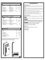
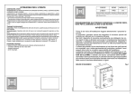
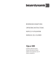
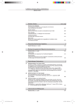
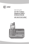
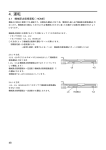
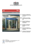
PROGRAMMATORE ELETTRONICO MONOFASE PER IL COMANDO DI PORTE E PORTONI MOTORIZZATI
SINGLE PHASE ELECTRONIC PROGRAMMER CONTROLLING MOTORISED GATES AND DOORS
PROGRAMMATEUR ELECTRONIQUE MONOPHASE POUR COMMANDE DE PORTES MOTORISEES
ELEKTRONISCHE STEUERUNG ZUR STEUERUNG VON AUTOMATISCHEN TOREN UND TÜREN
PROGRAMADOR ELECTRONICO MONOFASICO PARA EL CONTROL DE LAS PUERTAS MOTORIZADAS
L325.00
ITALIANO
AVVERTENZE
ISTRUZIONI PER L'INSTALLAZIONE
MONTAGGIO CONTENITORE
COLLEGAMENTO ELETTRICO
FUNZIONI SCHEDA LOGICA
ISTRUZIONI PER L'UTENTE
FRANCESE
REMARQUE
INSTRUCT. POUR L'INSTALLATION
MONTAGE DU BOÎTER
BRANCHEMENT ´ÉLECTRIQUE
FONCTIONS CARTE LOGIQUE
INSTRUCTIONES POUR L'UTILISATION
CARDIN ELETTRONICA spa
28
ESPAÑOL
03-05-2004
Via Raffaello, 36
31020 San Vendemiano (TV) Italy
Tel:
+39/0438.404011-401818
Fax:
+39/0438.401831
email (Italy):
Sales.offi[email protected]
email (Europe):
Sales.offi[email protected]
Http:
www.cardin.it
ADVERTENCIAS
INSTRUCCIONES PARA L'INSTALACION
MONTAJE DEL CONTENEDOR
CONEXIONES ELECTRICAS
FUNCIONES TARJETA LOGICA
INSTRUCCIONES DE USO
MOD: PRG101LS1
Pag. 5
Pag. 5
Pag. 6
Pag. 7
Pag. 8
Pag. 25
Pag. 13
Pag. 13
Pag. 14
Pag. 15
Pag. 16
Pag. 26
ENGLISH
REMARKS
INSTALLATION INSTRUCTIONS
CONTAINER INSTALLATION
ELECTRICAL CONNECTION
LOGIC CARD FUNCTIONS
INSTRUCTIONS FOR THE USER
DEUTSCH
ANWEISUNGEN
INSTALLATIONSANLEITUNGEN
MONTAGE DES GEHÄUSES
KLEMMLEISTENANSCHLÜSSE
FUNKTIONEN DER LOGIKKARTE
BETRIEBSANLEITUNG
Pag. 9
Pag. 9
Pag. 10
Pag. 11
Pag. 12
Pag. 25
Pag. 17
Pag. 17
Pag. 18
Pag. 19
Pag. 20
Pag. 26
Pag. 21
Pag. 21
Pag. 22
Pag. 23
Pag. 24
Pag. 27
1
Caratteristiche tecniche
Technical specifications
Alimentazione
Frequenza
Motori
Potenza max. motori
Corrente nominale
Temperature di esercizio
Grado di protezione
Grado di protezione con tasti
Grado di Ignifugazione
Power supply
Frequency
Motors
Power Input motors
Nominal current input
Operating temperature
Protection grade
Protection grade with buttons
Fireproofing class
INSTRUCCIONES DE USO
Vac
Hz
Nr.
W
Amp
°C
IP
IP
UL94
Caractéristiques techniques
Technische Daten
Alimentation
Fréquenze
Moteurs
Puissance maximum des moteurs
Courant nominal
Temperature di esercizio
Indice de protection
Indice de protection avec boutons
Indice d'ignifugation
Stromversorgung
Frequenz
Motoren
Motorenhöchstleistung
Nennstrom
Betriebstemperatur
Schutzgrad
Schutzgrad mit Steuerdrucktasten
Feuerschutzgrad
Vac
Hz
Nr.
W
Amp
°C
IP
IP
UL94
110
50/60
2
420 + 420
8.4
-20…+55
55
54
V0
110
50/60
2
420 + 420
8.4
-20…+55
55
54
V0
Especificaciones técnicas
Alimentación
Frecuencia
Motors
rights reserved. Unauthorised
copying
or usemotor
of the information contained in this document is punishable by law
Potencia
máx.
Corriente nominal
Temperatura de funcionamiento
Grado de protección
Grado de protección con pulsador
Grado de Ignifugación
Vac
Hz
N°
W
Amp
°C
IP
IP
UL94
110
50/60
2
420 + 420
8.4
-20…+55
55
54
V0
ADVERTENCIAS PARA EL USUARIO
PROGRAMADOR ELECTRONICO PARA INSTALACIONES DE AUTOMATIZACION DE PUERTAS FABRICADO CUMPLIENDO CON
LAS NORMAS.
Este aparato es un componente de la instalación; por tanto se lo debe instalar y equipar con aparatos fabricados cumpliendo con las
normas vigentes. La instalación debe ser realizada por personal habilitado para la instalación de “Aparatos utilizadores de energía
eléctrica”.
- Cualquier anomalía detectada durante el funcionamiento requiere la intervención de personal cualificado.
- El manual técnico y la llave de cierre de la puerta, los tiene que guardar el usuario, en un lugar diferente al del aparato (fuera del
alcance de los niños), y se los entregará al técnico en caso de operaciones sucesivas al emplazamiento.
- No tapar con objetos ni apoyar pesos en el aparato. Este último siempre debe ser accesible para los varios controles.
Tipología funcionamientos
Automático: Arranque y final del ciclo de trabajo, apertura-pausa-cierre con un solo impulso.
Semiautomático: Gestión del ciclo de trabajo mediante mandos separados de apertura y
cierre.
Persona presente: Movimiento de la mecánica sólo ante el mando continuo de movimiento.
Cualquier interrupción del mando de movimiento (soltando el pulsador) da lugar al stop.
Mando a distancia: El aparato está predispuesto para la inserción de una tarjeta radiorreceptor
(uno o dos canales), ésta permite el mando a distancia de todas las funciones.
Canal 1 se utiliza para el mando de movimiento (apertura, cierre), (TD).
Canal 2 se utiliza como botón de bloqueo (véase TB).
Posibilidad de uso
El aparato es especialmente adecuado para el accionamiento de:
- puertas de dos hojas
- puertas correderas
- puertas de garages.
All rights reserved. Unauthorised copying or use of the information contained in this document is punishable by law
Dimensioni d'ingombro - External dimensions - Dimensions d'encombrement
Außenabmessungen - Dimensiones del espacio ocupado
25
105
40
250
265
175
27,5
40
40
40
27,5
Fig. 2
2
27
Scheda base-Mother board-Carte de base-Träger-Leiterplatte-Tarjeta básica
2
3
9
PW
8
Jumper A-B
RECEIVER CARD
Output
Contact
CH2 NA
1
7
A
B
C
FUSE
F10A
MIN
14
15
16
17
18
19
20
21
22
23
COMMON
CLOSING M1
OPENING M1
C.
M1
4
FUSE
F10A
10
1
13
9
F
12
M2
8
7
Common
C.
NC NC NC NC
11
6
CH.
5
4
AP.
32
AP.
31
CH.
30
Common
OPENING M2
CLOSING M2
29
LS
28
LP 24V.
FCC
BETRIEBSANLEITUNG
27
FTC_I
26
FTC_S
25
FCA
24
TORQUE LIMIT
A
Possibilités d'application
L'appareil est particulièrement indiqué pour l'actionnement de:
- portails battants à deux vantaux;
- portails coulissants;
- portes de garage.
110V~
12V ac
TA
TC
TB
TD
TAL
BSP
24V ac
ELS
4
CS901 DC0281
3
NO NO NC NO NO
NC
2
N
26
Torque limiter
6
AX
10
5
LOGIC CARD
Types de fonctionnement
Automatique: enclenchement et déroulement du cycle de travail, ouverture-arrêt-fermeture,
par une seule impulsion.
Semi-automatique: gestion du cycle de travail par commandes d'ouverture et fermeture
séparées.
Fonctionnement manuel: manœuvre obtenue seulement par commande continue de mouvement. Chaque interruption de la commande de mouvement (relâchement du bouton-poussoir) provoque l'arrêt.
Commande à distance: l'appareil est prédisposé pour l'insertion d'une carte radio réceptrice
(un-deux canaux), ce qui permet de commander toutes les fonctions à distance.
Le canal 1 sera utilisé pour la commande de mouvement (ouverture, fermeture) (TD).
Le canal 2 sera utilisé comme touche de blocage (voir TB).
ANWEISUNGEN FÜR DIE BEDIENUNGSPERSON
ELEKTRONISCHER STEUERUNG FÜR AUTOMATISCHE STEUERANLAGEN VON TÜREN UND TOREN, KONSTRUIERT GEMÄSS
DEN VORSCHRIFTEN.
Die Apparatur ist ein Bestandteil der Anlage und muß als solche installiert und mit anderen Apparaturen, die gemäß den geltenden
Bestimmungen hergestellt wurden, vervollständigt werden. Die Installation muß von Personal ausgeführt werden, das im Sinne des
Gesetzes zur Installation von “Elektrogeräten” befähigt ist.
- Jede gefundene Unregelmäßigkeit beim Betrieb erfordert das Eingreifen von Fachpersonal.
- Das technische Handbuch und der Schlüssel zur Schließung der Tür verbleiben im Besitz der Bedienungsperson und müssen an
einem anderen Ort als den der Apparatur (und für Kinder unzugänglich) aufbewahrt werden. Sie müssen nach der Installationsmontage
im Falle eines Eingriffs dem Techniker gegeben werden.
- Es sollte vermieden werden, die Apparatur mit Gegenständen zu verdecken oder schwere Dinge auf ihr abzulegen. Sie muß für die
verschiedenen Kontrollen immer zugänglich sein.
Funktionsweisen
Automatisch: Start und vollständige Ausführung des Arbeitszykluses, Öffnen-Pause-Schließen
mit einem einzigen Impuls.
Halbautomatisch: Steuerung des Arbeitszykluses mit voneinander getrennten Befehlen zum
Öffnen und Schließen.
Anwesende Bedienungsperson: Betätigung der Mechanik nur bei dauerndem Bewegungsbefehl. Jede Unterbrechung des Bewegungsbefehls (Loslassen der Drucktaste) führt zum Stop.
Fernsteuerung: Die Apparatur ist für den Einsatz einer Funkempfängerkarte (ein-zwei Kanäle),
welche die Fernsteuerung aller Funktionen ermöglicht, vorbereitet.
Kanal 1 wird für den Bewegungsbefehl (Öffnen, Schließen) benutzt, (TD).
Kanal 2 wird als Blockiertaste (siehe TB) benutzt.
Anwendungsmöglichkeiten
Die Apparatur ist besonders geeignet zur Betätigung von:
- Flügeltoren mit zwei Flügeln
- Schiebetoren
- Garagentoren
FUSE
ELS
T1,6A
FUSE
F1A
M
INSTRUCTIONS POUR L'UTILISATION
PRÉCONISATION
PROGRAMMATEUR ÉLECTRONIQUE CONFORME AUX NORMES POUR INSTALLATIONS D'AUTOMATISATION DE PORTES ET
PORTAILS
L'appareil est un composant de l'installation; il doit être installé comme tel et couplé avec des appareils construits conformément
aux normes en vigueur. L'installation doit être exécutée par un personnel titulaire d'un certificat d'aptitude professionnelle pour
l'installation des APPAREILS ÉLECTRIQUES aux termes de la loi.
- Toute anomalie de fonctionnement nécessite l'intervention d'un personnel qualifié.
- Le livret d'instructions et la clé de fermeture du portillon restent en possession de l'usager qui ne devra pas les conserver à proximité de l'appareil (hors de portée des enfants). Ils devront être consignés au technicien en cas d'intervention sur l'appareil après sa
mise en place.
- Éviter de couvrir ou de poser des poids sur l'appareil. Celui-ci doit toujours être accessible pour les différents contrôles.
I componenti "A" sono presenti solo nella versione PRG101LS1.
The components "A" are only ptesent in the PRG101LS1 version.
Les composants "A" ne sont présents que dans la version PRG101LS1.
Die Komponenten "A" gibt es nur bei der Version PRG101LS1.
Los componentes "A" estan presentes sólo en el versión PRG101LS1
Legende
1 Regolatore di coppia
2 Fusibile 1A - protezione sovraccarichi 24V
3 Fusibile 1,6A ritardato - protez. elettroserratura
4 N°2 Fusibili 10A - protez. sovraccarichi 110V
5 Interfaccia scheda logicaDescription : Scheda
Drawing number : DC0281
6 Interfaccia scheda radio
7 Uscita contatto CH2
Product Code : PRG101LSO
8 Connettore pulsantiera
9 Ponticello selezione secondo canale (TB)
10 Ponticello
selezione contato N.A. secondo canale
Date
: 11-03-96
Draft : P.J.Heath
PW Led scheda alimentata
Zeichenerklärrung
1 Drehmomentregler
2 Sicherung 1A - Überlastungsschutz 24V
3 Sicherung 1,6A träge - Schutz Elektroschloß
4 2 Sicherungen 10A - Überlastungsschutz 110Vac
5 Logikkarte
base
(110Vac)
6 Funkkarte
7 Ausgang - Anschluß CH2
8 Anschluß für externe Drucktasten
9 Überbrückung zur Wahl des zweiten Kanals (TB)
10 Überbrückung zur Wahl des Kontaktes N.A. zweiter Kanal
PW Led - Stromversorgung der Karte
PRG101LSO CE
CARDIN ELETTRONICA
S.p.A - 31020 San Vendemiano
(TV) Italy - via Raffaello, 36 Tel: 0438/401818
Légende
Legende Fax: 0438/401831
Legend
1
2
3
4
5
6
7
8
9
10
PW
Torque limiter
Fuse 1A - overload protection 24V
Fuse 1,6A delayed - electric locking device
2 fuses 10A - overload protection 110V
Logic card interface
Radio receiver card interface
Contact in output CH2
Control button connection
Jumper second channel function (TB)
Jumper second channel function N.O
Led Power on
1 Régulateur de couple
1 Regulador de torsión
2 Fusibile 1A - protection surcharges 24V
2 Fusible 1A - protección sobrecargas 24V
3 Fusibile 1,6A ritard- protection serrure électrique 3 Fusible 1.6A retardado - protección electrocerradura
4 2 Fusibile 10A - protection surcharges 110V
4 N° 2 Fusibles 10A - protección sobrecargas 110Vac
5 Carte logique
5 Tarjeta lógica
6 Carte radio
6 Tarjeta radio
7 Sortie contact CH2
7 Salida contacto CH2
8 Connecteur pour boutons-poussoirs extérieurs 8 Conector para pulsadores exteriores
9 Pont sélection deuxième canal (TB)
9 Puente selección segundo canal (TB)
10 Pont sélection contact N.A deuxième canal
10 Puente selección contacto N.A. segundo canal
PW Led carte alimentée
PW Piloto tarjeta sometida a tensión
Fig. 3
3
ISTRUZIONI PER L'USO
Scheda logica-Logic card-Carte logique-Logikkarte-Tarjeta logica
TRC
T4
TAL
1
2
3
ON
TCA
+
T2
2M2302M
T1
2M2302M
+
TL
+
Void
2M2302M
Void
Void
LS
T3
+
DC0073
2M2302M
CS763
TCA
AU/UP
BA
LED TB
LED FTC-S
Void
LED FTC-I
Void
Void
+
Void
Void
Legenda
TRC Trimmer tempo di ritardo in chiusura
TL Trimmer tempo di lavoro
TAL Trimmer tempo di apertura limitata
TCA Trimmer tempo di richiusura automatica
LED SPIA:
stato di funzionamento delle sicurezze
Led accesi:
sicurezze abilitate (o ponticellate se non utilizzate)
Led spenti:
sicurezze non attivate, in avaria o in fase di intervento
(non correttamente ponticellate se non utilizzate)
Legend
DC0073
G101LSO
TRC Closing time delay trimmer
TL Work cycle setting trimmer
TAL Limited opening time trimmer
TCA Automatic reclosing time trimmer
INDICATOR LEDS: Safety device status
Lit leds: indicate enabled safety devices (to be jumped if not in use)
Leds off: indicate that the safety devices are either not activated, functioning incorrectly (damaged), in the process of intervening (working)
or incorrectly jumped (for unused safety devices)
Description : Scheda logica
Légende
PRG101LSO
TRC Trimmer réglage du réglage temps de retard en fermeture
TL Trimmer réglage du temps de travail
TAL Trimmer réglage du temps d'ouverture limitée
TCA Trimmer réglage du temps de refermeture auto
LAMPES TEMOIN:
Etat de fonctionnement
dispositifs
sécurité
31020
San Vendemiano
(TV) des
Italy
- via de
Raffaello,
Led allumés: dispositifs de sécurité activés (ou court-circuités s'ils
sont inutilisés)
Led éteints: dispositifs de sécurité désactivés, endommagés ou en phase
d'intervention (court-circuités de façon incorrecte s'ils sont inutilisés).
Zeichenerklärung
TRC Trimmer Regelung der automatischen Schließungszeit
TL
Trimmer Regelung der sicherheitlichen Betriebszeit
TAL Trimmer Zeitregelung der begrenzten Öffnung
TCA Trimmer Regelung der Verzögerungszeit beim Schließen
KONTROLL-LED: Betriebszustand der Sicherheitsvorrichtungen
Led leuchten: Sicherheitsvorrichtungen sind befähigt (oder überbrückt
falls nicht benutzt)
Led leuchten nicht: Sicherheitsvorrichtungen sind nicht befähigt,
in Panne oder im Einsatz (sie sind bei Nichtgebrauch nicht richtig
überbrückt worden).
Leyenda
TRC Trimmer tiempo de retardo en la fase de cierre
TL Trimmer tiempo de trabajo
TAL Trimmer tiempo de apertura limitada
TCA Trimmer tiempo de cierre automático
PILOTOS:
Estado de funcionamiento de los dispositivos de seguridad
Pilotos encendidos: dispositivos de seguridad habilitados (o conectados
en puente si no se los utiliza)
Pilotos apagados: dispositivos de seguridad deshabilitados, dañados
o en fase de actuación (o conectados en puente incorrectamente si
no se los utiliza)
Date : 31-05-01
CA S.p.A -
4
36 Tel: 0438/401818 Fax: 0438/401831
AVVERTENZE PER L'UTENTE
PROGRAMMATORE ELETTRONICO PER IMPIANTI D'AUTOMAZIONE PER PORTE E CANCELLI COSTRUITO SECONDO LE
NORMATIVE.
L'apparecchiatura é una componente d'impianto ; come tale va installata e implementata con apparecchiature , costruite secondo le
norme vigenti . L'installazione deve essere eseguita da personale abilitato all'installazione di "Apparecchi utilizzatori di energia elettrica"
ai sensi della legge in vigore.
- Ogni anomalia di funzionamento riscontrata richiede l'intervento di personale abilitato.
- Il manuale tecnico e la chiave di chiusura del portello , restano in possesso dell'utente e conservati in luogo diverso da quello dell'apparecchiatura (fuori della portata di bambini) ,saranno consegnati al tecnico in caso di interventi successivi alla posa.
- Evitare, di coprire con oggetti o appoggiare pesi sull'apparecchiatura . La stessa deve essere sempre accessibile per i vari controlli.
Tipologia funzionamenti
Automatico: Avvio e completamento del ciclo di lavoro, apertura-pausa-chiusura con un solo
impulso.
Semiautomatico: Gestione del ciclo di lavoro con comandi separati di apertura e chiusura.
Uomo presente: Movimentazione della meccanica solo in presenza di comando continuo di
moto. Ogni interruzione del comando di moto (rilascio del pulsante) attua lo stop.
Comando a distanza: L’apparecchiatura è predisposta per l’inserimento di una scheda radio
ricevente (uno-due canali), questa permette il comando a distanza di tutte le funzioni.
Canale 1 sarà utilizzato per il comando di moto (apertura, chiusura), (TD).
Canale 2 sarà utilizzato come tasto di blocco (vedi TB)
Possibilità d'impiego
L'apparecchiatura è particolarmente indicata all'azionamento di:
- cancelli a battente a due ante
- cancelli scorrevoli
- porte di garage.
INSTRUCTIONS FOR THE USER
CAUTION FOR THE USER
ELECTRONIC PROGRAMMER FOR USE WITH AUTOMATIC INSTALLATIONS FOR GATES AND DOORS BUILT ACCORDING TO
THE STANDARDS.
The appliance is part of an automatic installation; and as such should be installed together with appliances constructed according to
the laws and standards in force. The installation must be carried out by professionally qualified "installers of electrical equipment" in
conformity with the standards in force.
- Any eventual failures or operational anomalies require the intervention of a qualified technician.
- The instruction manual and the door key remain in the possession of the user and should be kept in a place separate from the
appliance and out of reach of children. They should be given to the technician as and when required for any eventual maintenance
interventions.
- Avoid covering or placing heavy objects on the appliance. The appliance must always be accessable for checks if necessary
Types of operation
Automatic: Start up and completion of the work cycle; Open-pause-close with one impulse.
Semi-automatic: Work cycle control using separate opening and closing commands.
Manual: Movement of the apparatus is only obtained while a continuous movement command
is present (keeping the button pressed). The apparatus will stop whenever the continuous
command is interrupted (releasing the button)
Remote control: The appliance is factory set for the insertion of a receiver card (one or two
channels). This will allow the remote activation of all the functions.
Channel 1 is used for the movement commands (opening, closing), (TD).
Channel 2 is used for the stop commands (see TB) or as an N.A. output (see jumpers A-B).
Use
This appliance is suitable for the following:
- Single and double hinged gates;
- Sliding gates;
- Garage doors.
Fig. 4
25
REGULACIÓN DEL LIMITADOR DE TORSIÓN
El par de torsión se puede ajustar en los valores mínimos, puesto que el aparato suministra un impulso
a la máxima potencia por cada mando de movimiento recibido (sólo en la versión LS1).
M
AX
e limiter
A
B
C
MIN
A
M1
Posición “Máx.” corresponde a: 110 Vac
Posición “A” corresponde a: 100 Vac
Posición “B” corresponde a: 90 Vac
Posición “C” corresponde a: 80 Vac
Posición “Mín.” corresponde a: 70 Vac
ON
M1
PUENTE - SELECCIÓN SEGUNDO CANAL
Caso de que se incorpore una tarjeta receptora de dos canales, el segundo canal se puede utilizar:
1) como tecla de bloqueo introduciendo los puentes según lo representado por el detalle 1
2) mando N.A. en los bornes introduciendo los puentes según lo representado por el detalle 2.
Puente
Det. 1
Puente
Det. 2
salida
CH2 RX
Contacto
Mando
N.A
TB
Importante: Con el receptor de un solo canal, los puentes se deben disponer como en el detalle 2.
FUNCIONES TARJETA LOGICA EXTRAIBLE (Fig. 4)
DIP-SWITCH de 3 vías
DIP 1 Opción cierre automático
- ON habilitado el cierre automático que se realiza después del tiempo de pausa prefijado por
el trimmer TCA de 3…100 s.
- OFF se obtiene un ciclo de trabajo semiautomático, su cumplimiento exige diferentes
mandos de apertura-cierre.
DIP 2 Selección funcionamiento automático / persona presente
- ON funcionamiento persona presente
- OFF funcionamiento automático o semiautomático
DIP 3 Opción inversión del sentido de marcha, actúa sobre el botón dinámico TD.
- ON evita la inversión durante la fase de apertura
- OFF mandos en secuencia de apertura y cierre, tanto en la fase de apertura como de cierre.
TRIMMER TL
Regulación del tiempo de trabajo (de 6 a 130 s) la cuenta del tiempo empieza al llegar un mando de
movimiento (apertura o cierre). N.B.: Al sistema por microinterruptor de tope electrónico está acoplado el sistema por tope mecánico. Por tanto se debe ajustar el trimmer de modo que se obtenga
un tiempo de trabajo algo superior al de actuación de los topes mecánicos.
TRIMMER TAL
Regulación del tiempo de apertura limitada, actúa con el mando TAL (de 3 a 25 s) (sólo con funcionamiento automático y semiautomático).
Cuidado: el mando de apertura limitada actúa sobre el motor M2; en la fase de cierre automático se
suman los tiempos de cierre TCA y el tiempo de retardo de la puerta. N.B.: en caso de aplicaciones
a puertas de una hoja (1 motor) con conexión motor en M2 hay que poner a cero el trimmer TRC.
TRIMMER TCA
Regulación tiempo de cierre automático (de 3 a 100).
N.B.: Por cada intervención de las fotocélulas de inversión el tiempo vuelve a partir de cero.
TRIMMER TRC
Regulación del tiempo de retardo durante la fase de cierre motor 2 (de 0 a 10) TRC. El cierre se
realiza durante el entero tiempo de trabajo TL y no durante el tiempo programado para la apertura
con TAL. N.B.: Tiempo de retardo fijo para la apertura de 2 s.
PUENTE LS
Predisposición para indicador luminoso de puerta abierta, con el funcionamiento por topes mecánicos
o microinterruptores de tope electrónico (véase descripción borne 30).
24
ITALIANO
ITALIANO
AVVERTENZE
Prima di dar inizio all’installazione leggere attentamente il presente fascicolo.
In particolare, prendere visione dei dispositivi di sicurezza previsti dal prodotto per utilizzarli
con la massima efficacia.
Non tutti i dispositivi di sicurezza eventualmente resi obbligatori da norme vigenti in Italia o
all’estero sono presi in considerazione dal presente fascicolo. L’installatore dovrà provvedervi personalmente, integrando i dispositivi mancanti ed installandoli a monte o a valle dei
prodotti descritti nel presente fascicolo.
L’utilizzo dei prodotti e la loro destinazione ad usi diversi da quelli previsti e/o consigliati,
non è stata sperimentata dal costruttore, pertanto i lavori eseguiti sono sotto la completa
responsabilità dell’installatore.
Il presente manuale si rivolge a persone abilitate all'installazione di "APPARECCHI UTILIZZATORI
DI ENERGIA ELETTRICA" e richiede una buona conoscenza della tecnica , esercitata in forma
professionale. Il costruttore declina ogni responsibilità per eventuali danni provocati dalla
mancata osservanze nel installazione della norme di sicurezza attualmente in vigore
Descrizione
- Elettronica composta da scheda madre, con scheda logica estraibile inserita sugli appositi
connettori ad innesto obbligato
- contenitore da esterno in ABS con portello ad anta fissato su cerniere in acciaio cromato
(apertura 180°), guarnizione di tenuta in chiusura (IP 55)
- chiusura del portello a chiave
- fissaggi a parete previsti sul contenitore
- ingresso cavi di collegamento con pressacavo
- l collegamenti su morsettiera estraibile
- predisposizione innesto ricevitore radiocomando
- pulsanti esterni sullo sportello (opzionali)
Versioni
- Programmatore PRG101LS1 con limitatore di coppia e spunto iniziale alla
massima potenza
ISTRUZIONI PER L'INSTALLAZIONE
Caratteristiche tecniche
Alimentazione
Frequenza
Motori
Potenza max. motori
Corrente nominale
Temperature di esercizio
Grado di protezione
Grado di protezione con tasti
Grado di Ignifugazione
Vac
Hz
N°
W
Amp
°C
IP
IP
UL94
110
50/60
2
420+420
8.4
-20 + 55
55
54
V0
Il kit PRG101 comprende:
- Il programmatore PRG101LS1
- N° 2 chiavi
- Il libretto d'istruzioni
Posizionamento
In base alla tipologia e alle caratteristiche d'impianto individuare il punto di posa dell'apparecchiatura. L'apparecchiatura dovrà essere collocata:
- al riparo da urti e manomissioni;
- ad altezza sufficiente dal suolo, al riparo da possibili colmi d'acqua:
- in una posizione facilmente raggiungibile dal tecnico, per interventi di manutenzione.
5
Procedura di montaggio contenitore
CONEXIONES ELECTRICAS
1
Antes de realizar las conexiones eléctricas, cerciorarse de que la tensión y la frecuencia indicadas en la
placa de características coincidan con las de la instalación de alimentación.
N.B.: El instalador tiene que proceder a la regulación del selector seleccionando la tensión más apropiada a
base
del peso (según
lo indicado
pagina
24) y las dimensiones
la puerta
que se
que desplazar.
All rights reserved.
Unauthorised
copying
or useenoflathe
information
contained inde
this
document
istiene
punishable
by law
Las vigentes normas de seguridad indican un empuje máximo en la parte final de la puerta igual a 15 kg. Para
llevar a cabo la regulación ejecutar unas maniobras de prueba averiguando si el calibrado es correcto.
A
Svitare le viti "B" ed estrarre il circuito
"C" dal contenitore con cura riponendolo
momentaneamente a riparo da polvere e
possibili urti.
All rights reserved. Unauthorised copying or use of the information contained in this document is punishable by law
B
A
C
M AX A
B
B
D
C
2
E
F
160 MM
Tracciare (con l'ausilio della scatola ) i quattro
punti di fissaggio a muro;
-fissare il contenitore utilizzando le quattro viti
e tasselli "G" in dotazione ed inserire i Drawing
tappi
di
Description :
number : DM0134
copertura viti "H"
Product Code : PRG
Inserimento scheda PRG
al
-Controllare il corretto fissaggio dei raccordi
"D"
Date : 27-04-98
Draft : P.J.Heath
All rights reserved. Unauthorised copying or use of the information contained in this document is punishable by law
CARDIN ELETTRONICA S.p.A - 31020 San Vendemiano (TV) Italy - via Raffaello, 36 Tel: 0438/401818 Fax: 0438/401831
contenitore
H
G
3
M
130 M
Reinserire il circuito nel contenitore e fissarlo con le apposite viti "B"
- inserire i tubi rigidi di collegamento "I" sugli appositi raccordi. I cavi della linea 110Vac vengono fatti passare nei
tubi 1 e 2 (vedi figure), separati dai cavi di collegamento in
bassa tensione che passono nei tubi 3 e 4.
- effettuare i collegamenti elettrico seguendo lo schema
allegato.
N.B. TODOS LOS CONTACTOS N.C. SIN UTILIZAR SE TIENEN QUE CONECTAR EN PUENTE
M AX
LS
FCC
FTC_I
FTC_S
B C
FCA
32
5
C.
16
17
NC
18
19
20
NO NO NC NO NO
21
22
M1
23
110V~
12V ac
ELS
4
CS901 DC0282
TA
TC
TB
TD
TAL
1
15
24V ac
2
14
3
3
13
BSP
I
4
12
2
Date : 27-04-98
11
C.
10
1
Installazione contenitore PRG
9
N
Product Code : LPRG
8
7
F
M2
NC NC NC NC
Drawing number : DM0135
6
CH.
31
Common
30
AP.
29
A
M IN
CARDIN ELETTRONICA S.p.A - 31020 San Vendemiano (TV) Italy - via Raffaello, 36 Tel: 0438/401818 Fax: 0438/401831
6
28
Common
27
AP.
26
CH.
25
LP 24V.
24
Description :
Draft : P.J.Heath
CONEXIONES A LA BORNERA
1-2
Alimentación programador 110 Vac 50/60 Hz
3Entrada tierra alimentación general
4Salida tierra motor
5-6-7
Salida mando motor M2 Cierre-Apertura-Común
8-9-10
Salida mando motor M1 Apertura-Cierre-Común
11-12
BSP entrada N.C. seguridad pasiva
Si está abierta corta la alimentación a la sección de mando, incluyendo la electrónica. Introducir un
contacto normalmente cerrado capaz de soportar una carga de 30 Vdc 100 mA. Este dispositivo
de seguridad se instala además de los dispositivos de seguridad activa (Cuidado: No se puede
conectar en serie esta entrada con FTCI y FTCS puesto que la BSP no tiene el mismo commun.
Su conexión se puede efectuar en el borde neumático fijo como dispositivo antiaplastamiento o
en los dispositivos de urgencia, siempre cumpliendo con las normas.
15
TAL Tecla de apertura limitada, funcionamiento automático y semiautomático (sólo M2)
16
TD (contacto N.A.) entrada pulsador dinámico para Abrir-Cerrar
17
TB (contacto N.C.) entrada pulsador de bloqueo (al abrirse el contacto detiene el ciclo de trabajo
hasta el nuevo mando de movimiento)
18
TC (contacto N.A.) entrada pulsador de cierre
19
TA (contacto N.A.) entrada pulsador de apertura
32-13-14 Común para todas las entradas y salidas (negativo)
20-21
Salida 24 Vac 5W alimentación dispositivos exteriores (fotocélulas, etc.)
22-23
Salida electrocerradura 12 Vac 12 W máx. (sólo durante la apertura)
24
Central antena radiorreceptor (N.B. conectar la antena mediante cable coaxial RG58 impedancia
50 Ω)
25
Masa antena radiorreceptor
26
FCC Entrada microinterruptor de tope de cierre motor 1 - motor 2 (contacto N.C.)
27
FCA Entrada microinterruptor de tope de apertura (contacto N.C.) motor 1 - motor 2
28
FTCS (Contacto N.C.) entrada para dispositivos de mando y seguridad (fotocélulas de stop).
La apertura del contacto, consiguiente a la actuación de los dispositivos de seguridad durante
las fases de cierre y apertura, detendrá el movimiento hasta que se elimine el obstáculo, y luego
la puerta seguirá en la dirección de marcha hasta el tope.
29
FTCI (Contacto N.C.) entrada para los dispositivos de mando y seguridad (fotocélula de inversión
durante la fase de cierre). La apertura del contacto, consiguiente a la actuación de los dispositivos
de seguridad, durante la fase de cierre, llevará a cabo la inversión del movimiento.
30
LS Salida 24 Vac 3 W luz indicadora de ciclo de trabajo en curso de actuación, se apaga una
vez finalizado el ciclo de trabajo.
- con topes mecánicos, puente LS en la posición de cerrado (fig. 4 pag. 4)
- con los microinterruptores de tope (a tiempo) puente LS en la posición de abierto. (fig. 4)
31
LP Salida centelleante 24 Vac 5W indicación de puerta en movimiento.
23
Collegamento elettrico
Procedimiento para el montaje del contenedor
Accertarsi, prima di eseguire il collegamento elettrico, che la tensione e la frequenza riportate sulla targhetta
All rights reserved. caratteristiche
Unauthorisedcorrispondano
copying or use
of the
informationdicontained
in this document is punishable by law
a quelle
dell'impianto
alimentazione.
1
N.B.: E' cura dell'installatore procedere alla regolazione del limitatore di coppia selezionando la tensione
più appropriata in base al peso (come indicato a pagina 8) e le dimensioni dell'anta da movimentare. Le
norme di sicurezza vigenti indicano una spinta max. in punta d'anta pari a 15 kg. Per eseguire la regolazione
compiere delle manovre di prova verificando la giusta calibratura.
A
Aflojar los tornillos “B” y sacar el circuito “C”
del contenedor, esto con sumo esmero colocándolo de momento en un lugar protegido
contra el polvo y los choques posibles.
All rights reserved. Unauthorised copying or use of the information contained in this document is punishable by law
B
A
C
M AX A
B
B
D
C
2
E
F
160 MM
Marcar (con la ayuda de la caja) los 4 puntos de fijación
en la pared:
- fijar el contenedor utilizando los cuatro tornillos y tacos
Description :
Drawing number
: DM0134
“G” suministrados e introducir los tapones
“H”
que
Product Code : PRG
Inserimento scheda PRG
cubren los tornillos.
Date : 27-04-98
Draft : P.J.Heath
- controlar la fijación correcta de los prensatubos
“D”
en
All rights reserved. Unauthorised copying or use of the information contained in this document is punishable by law
CARDIN ELETTRONICA S.p.A - 31020 San Vendemiano (TV) Italy - via Raffaello, 36 Tel: 0438/401818 Fax: 0438/401831
la caja.
H
G
M
130 M
3
11
12
13
14
15
16
17
18
19
20
21
22
NO NO NC NO NO
CH.
12V ac
24V ac
ELS
4
CS901 DC0282
TA
TC
TB
TD
TAL
BSP
NC
3
3
110V~
2
4
1
M1
N
I
2
C.
10
23
Installazione contenitore PRG
Date : 27-04-98
9
1
M2
8
7
Common
C.
NC NC NC NC
Description :
6
AP.
5
Common
32
AP.
31
LS
FCA
30
CH.
29
LP 24V.
28
FTC_I
M AX
FCC
27
FTC_S
26
M IN
CARDIN ELETTRONICA S.p.A - 31020 San Vendemiano (TV) Italy - via Raffaello, 36 Tel: 0438/401818 Fax: 0438/401831
22
25
F
Draft : P.J.Heath
24
B C
Product Code : LPRG
N.B. TUTTI I CONTATTI N.C. NON UTILIZZATI VANNO PONTICELLATI
A
Volver a colocar el circuito en el contenedor y fijarlo por
medio de los tornillos “B” correspondientes.
- inserir los tubos de empalme “I” en los prensatubos
correspondientes. Los cables de la línea de 110 Vac
se hacen pasar por los tubos 1 y 2 (véanse las figuras),
separados de los cables de conexión de baja tensión
que pasan por los tubos 3 y 4;
- realizar las conexiones eléctricas siguiendo el esquema adjunto.
Drawing number : DM0135
COLLEGAMENTI MORSETTIERA
1-2
Alimentazione programmatore 110 Vac 50/60 Hz
3
Ingresso terra alimentazione generale
4
Uscita terra motore
5-6-7
Uscita comando motore M2 Chiusura-Apertura-Comune
8-9-10
Uscita comando motore M1 Apertura-Chiusura-Comune
11-12
BSP Ingresso N.C. sicurezza passiva
Se aperto interrompe l'alimentazione alla parte di comando, compresa l'elettronica. Inserire
un contatto normalmente chiuso in grado di sopportare un carico di 30V dc 100 mA. Questo
dispositivo di sicurezza viene installato in aggiunta ai normali dispositivi di sicurezza attiva
(Attenzione! Non è possibile collegare questo ingresso in serie ad FTCI-FTCS dato che
la BSP non ha lo stesso comune). Il suo collegamento può essere eseguito sulle costa
pneumatiche fissa come anticonvogliamento o su dispositivi di estrema emergenze, sempre
rispettando le norme in vigore.
15
TAL Tasto apertura limitata, funzionamento automatico e semiautomatico (solo M2)
16
TD (contatto N.A.) ingresso pulsante dinamico Apre -Chiude
17
TB (contatto N.C.) ingresso pulsante di blocco (alla sua apertura il contatto
interrompe il ciclo di lavoro fino ad un nuovo comando di moto)
18
TC (contatto N.A.) Ingresso pulsante di chiusura
19
TA (contatto N.A.) Ingresso pulsante di apertura
32-13-14 Comune per tutti gli ingressi e uscite (negativo)
20-21
Uscita 24 Vac 5W alimentazione dispositivi esterni (fotocellule, ecc.)
22-23
Uscita elettroserratura 12 Vac 12W max. (solo in apertura)
24
Centrale antenna ricevitore radio (N.B. collegare l'antenna con cavo coassiale RG58 impedenza
50 Ω)
25
Massa antenna ricevitore radio
26
FCC Ingresso finecorsa di chiusura motore 1- motore 2 (contatto N.C.)
27
FCA Ingresso finecorsa di apertura (contatto N.C.) motore 1-motore 2
28
FTCS (Contatto N.C.) ingresso per dispositivi di comando e sicurezza.
(fotocellula di stop). L'apertura del contatto, conseguente all'intervento dei dispositivi di sicurezza
durante le fasi di chiusura e apertura, attuerà l'arresto del moto fino alla rimozione dell'ostacolo,
dopo di che l'anta continuerà nella direzione di marcia fino a finecorsa.
29
FTCI (Contatto N.C.) ingresso per dispositivi di comando e sicurezza. (fotocellula di inversione
in chiusura). L'apertura del contatto, conseguente all'intervento dei dispositivi di sicurezza,
durante la fase di chiusura, attuerà l'inversione di moto.
30
LS Uscita 24 Vac 3 W lampada spia segnalazione ciclo di lavoro in corso, si spegne a ciclo di
lavoro concluso.
- con finecorsa meccanici, ponticello LS in posizione chiuso (fig. 4 pag. 4).
- con finecorsa elettrici (a tempo) ponticello LS in posizione aperto (fig. 4 pag. 4).
31
LP Uscita lampeggiante 24 Vac 5W segnalazione portone in movimento.
7
Regolazione del limitatore di coppia
La coppia può essere regolata sui valori minimi, dato che l'apparecchiatura fornisce un impulso alla
massima potenza ad ogni comando di moto ricevuto (solo nella versione LS1).
AX
B
C
MIN
A
Ponticello
CH2 RX
Comando
TB
Dett. 2
ON
M1
M1
Ponticello - selezione secondo canale
Nel caso si inserisca una scheda ricevente bicanale, il secondo canale può essere utilizzato:
1) come tasto di blocco inserendo i ponticelli come raffigurato in dett. 1.
2) comando N.A. sui morsetti inserendo i ponticelli come raffigurato in dett. 2.
Dett. 1
Ponticello
uscita
Contatto
N.A
Importante: Con il ricevitore monocanale i ponticelli devono essere posizionati come in dett. 2
FUNZIONI SCHEDA LOGICA ESTRAIBILE 1 (fig. 4 pag. 4)
DIP- SWITCH a 3 vie
DIP 1
Opzione chiusura automatica
- ON inserita la chiusura automatica avviene dopo il tempo di pausa
predeterminato dal trimmer TCA da 3...100 s.
- OFF si ottiene un ciclo di lavoro semiautomatico, il suo compimento
richiede distinti comandi di apre-chiude.
DIP 2
Selezione funzionamento automatico / uomo presente
- ON funzionamento uomo presente
- OFF funzionamento automatico o semiautomatico
DIP 3
Opzione inversione di marcia , agisce sul tasto dinamico TD.
- ON evita l'inversione in fase di apertura.
- OFF comandi in sequenza apre e chiude, sia in fase di apertura che di chiusura
TRIMMER TL
Regolazione tempo di lavoro (da 6...130 s) il conteggio del tempo inizia all'arrivo di un comando di
moto (apertura o chiusura). N.B. Al sistema di finecorsa elettronico a tempo è affiancato il sistema di
finecorsa meccanico. Regolare quindi il trimmer in modo da ottenere un tempo di lavoro leggermente
superiore a quello di intervento dei finecorsa meccanici.
TRIMMER TAL
Regolazione tempo di apertura limitata, agisce con il comando TAL (da 3...25 s)
(solo con funzionamento automatico e semiautomatico).
Attenzione: Il comando di apertura limitata agisce sul motore M2; in fase di richiusura automatica si
sommano il tempo di richiusura TCA e il tempo di ritardo anta. NB: in caso di applicazioni ad anta
singola (1 motore ) con collegamento motore in M2 azzerare il trimmer TRC.
TRIMMER TCA
Regolazione tempo di richiusura automatica (da 3...100 s)
N.B. Ad ogni intervento delle fotocellule di inversione il tempo si rinnova.
TRIMMER TRC
Regolazione tempo di ritardo in chiusura motore 2 (da 0...10 s)
TRC. La richiusura avviene per l'intero tempo lavoro TL e non per il tempo impostato per l'apertura
con TAL. NB: Tempo ritardo in apertura fisso 2 s.
PONTICELLO LS
Predisposizione per lampada spia cancello aperto, al funzionamento con finecorsa meccanici o
elettronici (vedi descrizione morsetto 30).
8
ESPAÑOL
advertencias
Antes de dar inicio a la instalación, léase con esmero este manual.
En especial, véanse los dispositivos de seguridad dispuestos para el producto para poderlos
utilizar con la máxima eficacia.
M
e limiter
A
Posizione "Max" corrisponde a: 110Vac
Posizione "A" corrisponde a: 100Vac
Posizione "B" corrisponde a: 90Vac
Posizione "C" corrisponde a: 80Vac
Posizione "MIN" corrisponde a: 70Vac
ESPAÑOL
En este manual no se tratan todos los dispositivos de seguridad eventualmente obligatorios debido a las normas vigentes en Italia o al extranjero. El instalador tendrá que hacerse
cargo de esto, integrando los dispositivos faltantes e instalándolos antes o después de los
productos detallados en este manual.
El uso de los productos y su destino para usos diferentes a aquéllos previstos y/o aconsejados, no ha sido probado por el fabricante, por tanto los trabajos ejecutados están sometidos
a la total responsabilidad del instalador.
Este manual se dirige a personas habilitadas para la instalación de “APARATOS UTILIZADORES DE ENERGIA ELECTRICA” y exige el buen conocimiento de la técnica, realizada
profesionalmente. El fabricante no se responsabiliza de los daños eventuales debidos al
incumplimiento durante la instalación de las normas de seguridad actualmente vigentes.
Descripción
- Electrónica compuesta por la tarjeta principal, con tarjeta lógica extraíble inserida en los
conectores correspondientes de acoplamiento obligado
- contenedor para el exterior en ABS provisto de puerta sujetada por los goznes de acero
cromado (apertura 180°), junta hermética para el cierre (IP 55)
- cierre de la puerta mediante llave
- elementos de fijación en la pared dispuestos en el contenedor
- entrada de los cables de conexión con prensahilo
- las conexiones en la bornera extraíble
- predisposición acoplamiento receptor radiomando
- pulsadores exteriores en la puerta (opcionales)
Modelos
- Programador PRG101LS1 con limitador de torsión y arranque inicial a la máxima potencia
INSTRUCCIONES PARA LA INSTALACION
CARACTERÍSTICAS TÉCNICAS
Alimentación
Frecuencia
Motores
Potencia máx. motores
Corriente nominal
Temperaturas de funcionamiento
Grado de protección
Grado de protección con pulsadores
Grado de ignifugación
Vac
Hz
N°
W
Amp
°C
IP
IP
UL94
110
50/60
2
420+420
8.4
-20…+55
55
54
V0
El kit PRG101LS1 comprende:
- El programador PRG101LS1
- N° 2 llaves
- El manual de instrucciones
Emplazamiento
A base de la tipología y las características de la instalación, determinar el lugar de emplazamiento del aparato. El aparato se deberá colocar:
- en un lugar protegido contra los choques y las manipulaciones;
- a una altura suficiente del suelo, protegido de los remansos de agua posibles;
- en una posición fácilmente alcanzable por el técnico, para las operaciones de mantenimiento.
21
Regelung des Drehmoments
Das Drehmoment kann auf den niedrigsten Wert geregelt werden, da die Apparatur bei jedem eingehenden Bewegungsbefehl einen Impuls mit maximaler Kraft liefert (nur bei der Version LS1).
M
AX
e limiter
A
B
Position “MAX” entspricht: 110 Vac
Position “A” entspricht: 100 Vac
Position “B” entspricht: 90 Vac
Position “C” entspricht: 80 Vac
Position “MIN” entspricht: 70 Vac
C
MIN
A
ON
M1
M1
Überbrückung - Wahl des zweiten Kanals
Im Falle, dass eine Zweikanalempfängerkarte eingesetzt wird, kann der zweite Kanal benutzt werden:
1) als Blockiertaste indem die Überbrückungen wie in Detail 1 angezeigt aufgesetzt werden;
2) als Befehl N.A. auf den Klemmen indem die Überbrückungen wie in Detail 2 angezeigt aufgesetzt
werden.
Überbruckung
Det. 1
Überbruckung
Det. 2
Ausgang
CH2 RX
Kontakt
Steuerung
N.A
TB
Wichtig: Beim Einkanalempfänger müssen die Überbrückungen wie in Detail 2 aufgesetzt werden.
FUNKTIONEN DER HERAUSNEHMBAREN LOGIKKARTE 1 (Abb.4)
3-WEGE DIP-SWITCH
DIP 1
Wahlmöglichkeit automatisches Schließen
- ON : das automatische Schließen erfolgt nach der Pausenzeit, die durch den Trimmer TCA
von 3...100 s regelbar ist.
- OFF : halbautomatischer Zyklus, dessen Vollendung genaue Befehle zum Öffnen - Schließen
benötigt.
DIP 2
Wahl der Betriebsweise: automatisch/Bedienungsperson anwesend.
- ON Betrieb bei anwesender Bedienungsperson
- OFF automatischer oder halbautomatischer Betrieb.
DIP 3
Wahlmöglichkeit zur Laufrichtungsumkehrung; er wirkt auf die dynamische Taste TD.
- ON verhindert die Laufrichtungsumkehrung während der Öffnungsphase.
- OFF Befehlsfolge Öffnen und Schließen, sowohl in der Öffnungsphase als auch in der
Schließungsphase
TRIMMER TL
Regelung der Arbeitszeit (von 6...130 s). Die Berechnung der Zeit beginnt beim Eintreffen eines Bewegungsbefehls (Öffnen oder Schließen). Anmerkung: Dem zeitlich geregelte elektronische Endschaltersystem ist das mechanische Endschaltersystem beigestellt. Sie müssen also den Trimmer so einstellen,
dass die Arbeitszeit etwas länger ist als die Eingriffszeit der mechanischen Endschalter.
TRIMMER TAL
Zeitregelung der begrenzten Öffnung, wirkt mit dem Befehl TAL (von 3...25 s) (nur bei automatischem
und halbautomatischem Betrieb).
Achtung: Der Befehl zur begrenzten Öffnung wirkt auf den Motor M2; in der Phase des automatischen
Wiederschließens summieren sich die Zeit des Wiederschließens TCA und die Zeit der Torflügelbewegungsverzögerung. Anmerkung: Bei Anwendungen mit einem einzigen Torflügel (1 Motor) mit Anschluß
des Motors in M2 stellen Sie den Trimmer TRC auf Null.
TRIMMER TCA
Regelung der automatischen Schließungszeit (von 3...100 s).
Anmerkung: Bei jedem Einsatz der Lichtschranken für die Laufrichtungsumkehrung beginnt die Zeit
wieder von vorne.
TRIMMER TRC
Regelung der Verzögerungszeit beim Schließen Motor 2 (von 0…10 s)
TRC. Das Wiederschließen erfolgt über die gesamte Arbeitszeit TL und nicht über die für die Öffnung
mit TAL eingestellte Zeit.
Anmerkung: Fixe Verzögerungszeit beim Öffnen 2 s.
ÜBERBRÜCKUNG LS
Vorbereitung für Kontroll-Leuchte “Tor offen”, bei Betrieb mit mechanischen oder elektronischen
Endschaltern (siehe Beschreibung Klemmleiste 30).
20
ENGLISH
ENGLISH
REMARKS
Before commencing with the installation of this appliance make sure that you have read
the following instructions carefully. In particular familiarise yourself with the safety devices
required by the system, only then will you be able to use them to great effect.
Not all of the safety devices required by Italian or local safety standards have been taken into
consideration in this manual. The installer must make sure that any eventual safety devices
required by the local standards and regulations have been installed both ahead of and after
the products described in this manual.
This appliance must be used exclusively for the purpose for which it has been made. Any
non authorised modifications are to be considered improper and therefore dangerous. The
manufacturer accepts no liability for damage caused by, or situations arising from, the improper use of these appliances and therefore all work carried out after the delivery of the
appliance is to be considered the complete responsibility of the installer.
These instructions are aimed at professionally qualified "installers of electrical equipment"
in conformity with the local standards in force.
Description
- The electronic components consist of a mother board with an extractable logic card inserted
into one of the interface slots.
- All weather container in ABS with a stainless steel hinged inspection door (180° opening
angle), door sealing gasket (IP 55)
- Lockable inspection door
- Container fitted with wall fastening elements
- Power cable inlet complete with cable clamp
- Extractable terminal board connections
- Radio control receiver interface
- External control buttons (available on request)
Versions
- Programmer PRG101LS1 with torque limiter and maximum power initial thrust.
INSTALLATION INSTRUCTIONS
Technical specifications
Power supply
Frequency
Motors
Maximum power consumption motors
Nominal current input
Operating temperature
Protection grade
Protection grade with external control buttons
Fire protection grade
Vac
Hz
N°
W
Amp
°C
IP
IP
UL94
110
50/60
2
420+420
8.4
-20…+55
55
54
V0
The PRG101LS1 kit contains:
- The programmer PRG101LS1
- 2 keys
- The instruction manual
Positioning
Depending on the type of installation work out the position in which the programmer will be
situated remembering that the site must be:
- a position safe from accidental collision;
- high enough above the ground to be safe from pools of water;
- in a position which the technician can easily reach.
9
Container installation procedure
ELEKTRISCHER ANSCHLUSS
Vergewissern Sie sich vor der Ausführung des elektrischen Anschlusses, ob die auf dem Geräteschild
angegebene Spannung und Frequenz auch mit denen der elektrischen Versorgung übereinstimmen.
All rights reserved. Unauthorised
or use
of the information
contained
in this document
is punishable
Hinweis: Es istcopying
Aufgabe des
Installateurs
die Regelung
des Spannungsreglers
so vorzunehmen,
dassby
dielaw
für
das Gewicht und die Ausmaße des zu bewegenden Türflügels die am besten geeignete Spannung (wie auf
Seite 20 beschrieben) gewählt wird. Die geltenden Sicherheitsnormen geben einen maximalen Stoßdruck
an der Spitze des Türflügels von gleich 15 kg an. Zur Regulierung sollten Sie Probeläufe ausführen lassen,
um die richtige Trimmung herauszufinden.
160 MM
Using the container as a template mark the four points
at which the fastening holes are to be drilled;
- Fasten the container using the four screws and raw
Description :
number : DM0134
insert
the screw
plugs "G" (supplied with the device) andDrawing
Product Code : PRG
Inserimento scheda PRG
covering plugs "H".
Date : 27-04-98
Draft : P.J.Heath
that
they
are
- Insert the pipe fittings "D" and check
All rights
reserved. Unauthorised copying or use of the information contained in this document is punishable by law
CARDIN ELETTRONICA S.p.A - 31020 San Vendemiano (TV) Italy - via Raffaello, 36 Tel: 0438/401818 Fax: 0438/401831
fastened correctly.
H
G
M
130 M
3
26
27
M AX
29
FTC_S
FCA
FCC
M IN
30
31
32
5
M2
16
17
NC
18
19
20
NO NO NC NO NO
21
22
M1
23
110V~
TA
12V ac
ELS
4
CS901 DC0282
24V ac
TC
TB
TD
TAL
1
BSP
2
15
3
3
14
C.
10
2
I
4
13
9
N
Installazione contenitore PRG
Date : 27-04-98
12
8
7
1
11
6
C.
NC NC NC NC
Description :
CARDIN ELETTRONICA S.p.A - 31020 San Vendemiano (TV) Italy - via Raffaello, 36 Tel: 0438/401818 Fax: 0438/401831
10
28
F
Draft : P.J.Heath
25
B C
Product Code : LPRG
24
A
Re-insert the electronic card into the container and fasten
down using the screws "B".
- Insert the rigid electrical connection pipes "I" into the
cable tubes "D". The 110 Vac cables should be passed
through pipes 1 and 2 (see figure) so as to separate them
from the low voltage wires which should be passed through
pipes 3 and 4.
- Carry out the electrical connection following the attached
wiring diagram.
Drawing number : DM0135
CH.
F
Common
2
E
AP.
C
Common
C
M AX A
B
B
D
AP.
B
A
CH.
All rights reserved. Unauthorised copying or use of the information contained in this document is punishable by law
KLEMMLEISTENANSCHLÜSSE
1-2
Stromversorgung Steuerung 110 Vac 50/60 Hz
3
Eingang Erdung allgemeine Stromversorgung
4
Ausgang Motorenerdung
5-6-7
Ausgang Steuerung Motor M2 Schließen-Öffnen-Gemein
8-9-10
Ausgang Steuerung Motor M1 Öffnen-Schließen-Gemein
11-12
BSP Eingang N.C. passive Sicherheit
Falls geöffnet unterbricht sie die Stromversorgung von seiten der Steuerung einschließlich Elektronik.
Setzen Sie einen normalerweise geschlossenen Kontakt ein, der in der Lage ist, eine Belastung von
30V dc 100 mA zu vertragen. Diese Sicherheitsvorrichtung wird zusätzlich zu den normalen und
funktionsfähigen Sicherheitsvorrichtungen installiert (Achtung: Es ist nicht möglich diesen Eingang
in Reihe an FTCI, FTCS, anzuschließen, da die BSP keinen gemeinschaftlichen Leiter mit ihnen
hat. Ihr Anschluß kann unter Beachtung der Sicherheitsnormen auf den pneumatischen Leisten als
Quetschschutz erfolgen oder auf Vorrichtungen für äußerste Notfälle ausgeführt werden.
15
TAL Taste zur begrenzten Öffnung, Betriebsweise automatisch und halbautomatisch (nur M2)
16
TD (Einschaltglied-Kontakt) Eingang dynamische Taste Öffnen-Schließen
17
TB (Ausschaltglied-Kontakt) Eingang Blockiertaste (bei seiner Öffnung unterbricht der Kontakt den
Arbeitszyklus bis zu einem neuen Bewegungsbefehl)
18
TC (Einschaltglied-Kontakt) Eingang Schließtaste
19
TA (Einschaltglied-Kontakt) Eingang Öffnungstaste
32-13-14 Gemein für alle Eingänge und Ausgänge (negativ)
20-21
Ausgang 24 Vac 5 W Stromversorgung externer Vorrichtungen (Lichtschranken, usw.)
22-23
Ausgang elektrisches Schloß 12 Vac 12 W max. (nur beim Öffnen)
24
Innenleiter Funkempfängerantenne (Anmerkung: Verwenden Sie für die Antenne ein Koaxialkabel
RG58 Impedanz 50 Ω)
25
Außenleiter Funkempfängerantenne
26
FCC Eingang Endschalter beim Schließen Motor 1 - Motor 2 (Ausschaltglied-Kontakt)
27
FCA Eingang Endschalter beim Öffnen (Kontakt N.C.) Motor 1 - Motor 2
28
FTCS (Ausschaltglied-Kontakt) Eingang für Steuer- und Sicherheitsvorrichtungen. (Lichtschranke
für Stop)
Das auf das Eingreifen der Sicherheitsvorrichtungen während der Schließungs- und Öffnungsphase
herrührende Öffnen des Kontaktes führt zum Stillstand der Bewegung bis das Hindernis weggeräumt
wird. Danach fährt der Torflügel mit seiner Bewegung fort bis zum Endanschlag.
29
FTCI (Ausschaltglied-Kontakt) Eingang für Steuer- und Sicherheitsvorrichtungen. (Lichtschranke
für Laufrichtungsumkehrung beim Schließen). Das auf das Eingreifen der Sicherheitsvorrichtungen
während der Schließungsphase herrührende Öffnen des Kontaktes führt zur Laufrichtungsumkehrung.
30
LS Ausgang 24 Vac 3 W Kontroll-Leuchte zur Anzeige des sich im Verlauf befindlichen Arbeitszykluses, erlischt bei Abschluß des Arbeitszykluses.
- mit mechanischem Endschalter, Überbrückung LS in geschlossener Stellung (Abb. 4 St 4).
- mit elektrischem Endschalter (zeitgeregelt) Überbrückung LS in offener Stellung (Abb. 4).
31
LP Ausgang Blinklicht 24 Vac 5 W Anzeige des sich in Bewegung befindlichen Tores.
HINWEIS: ALLE NICHTBENUTZTEN N.C. KONTAKTE MÜSSEN ÜBERBRÜCKT WERDEN.
LS
Remove the screws "B" and carefully extract
the P.C.B. card "C" from the container remembering to store it somewhere safe from
dust and possible damage.
LP 24V.
A
FTC_I
1
19
ELECTRICAL CONNECTION
Montageverfahren des Gehäuses
1
Before connecting the appliance make sure that the voltage and frequency rated on the data plate conform
to those of the mains supply.
All rights reserved. Unauthorised
copying
or the
usetorque
of theselector
information
in this document
is punishable
law
NB: The installer
must set
switchcontained
to the appropriate
voltage depending
on the by
weight
and dimensions of the gate which is to be automated. The safety standards indicate a maximum thrust at
the head of the gate equal to 15 kg.
Carry out trial movements to verify the correct calibration of the system.
A
Schrauben Sie die Schrauben “B” los und
entnehmen Sie vorsichtig den Schaltkreis
“C” aus dem Gehäuse und legen Sie ihn
vorläufig an einen vor Staub und möglichen
Stößen geschützten Ort.
All rights reserved. Unauthorised copying or use of the information contained in this document is punishable by law
B
A
C
M AX A
B
B
D
C
2
E
F
160 MM
Skizzieren Sie (unter Zuhilfenahme des Kastens) die vier
Befestigungspunkte an die Wand.
- Schrauben Sie unter Verwendung der vier mitgelieferten
Description :
: DM0134
Schrauben und Dübel “G” das GehäuseDrawing
an number
die Wand
Product Code
: PRG
Inserimento scheda PRG
und setzen Sie die Schraubenabdeckungen
“H”
ein.
Date : 27-04-98
Draft : P.J.Heath
- Kontrollieren Sie den festen Sitz der Rohrklemmen
“D”
All rights reserved. Unauthorised copying or use of the information contained in this document is punishable by law
CARDIN ELETTRONICA S.p.A - 31020 San Vendemiano (TV) Italy - via Raffaello, 36 Tel: 0438/401818 Fax: 0438/401831
im Kasten.
H
G
M
130 M
3
C.
11
16
17
NC
18
19
20
NO NO NC NO NO
21
22
M1
23
110V~
12V ac
24V ac
ELS
4
CS901 DC0282
TA
TC
TB
TD
TAL
1
BSP
2
15
3
3
14
C.
10
2
I
4
13
9
N
Installazione contenitore PRG
Date : 27-04-98
12
8
7
1
M2
NC NC NC NC
Description :
6
CH.
5
Common
32
AP.
31
Common
30
AP.
FTC_S
FCA
FCC
29
CH.
M AX
M IN
CARDIN ELETTRONICA S.p.A - 31020 San Vendemiano (TV) Italy - via Raffaello, 36 Tel: 0438/401818 Fax: 0438/401831
18
28
LS
27
LP 24V.
26
FTC_I
25
F
Draft : P.J.Heath
24
B C
Product Code : LPRG
N.B.: All unused NC contacts must be jumped
A
Setzen Sie den Schaltkreis wieder in das Gehäuse ein und
schrauben Sie ihn mit den dafür vorgesehenen Schrauben
“B” fest.
- Führen Sie die Anschlußrohre “I” in die dafür vorgesehenen
Rohrklemmen ein. Die Kabel der 110 Vac Leitung werden
durch die Rohre 1 und 2 geführt (siehe Abbildungen), also
getrennt von den Verbindungskabeln mit Niedrigspannung,
die durch die Rohre 3 und 4 laufen.
- Führen Sie die elektrischen Anschlüsse aus, indem Sie
sie das beigelegte Schema beachten.
Drawing number : DM0135
TERMINAL BOARD CONNECTIONS
1-2
Electronic programmer power supply 110 Vac 50/60 Hz
3
Earth binding post (mains supply)
4
Motor earthing wire (in output)
5-6-7
Motor M2 in output Closing- Opening- Common
8-9-10
Motor M1 in output Opening- Closing- Common
11-12
BSP Passive safety input (N.C.)
If this contact is open the power supply to the controls (including the electronic card) will be
interrupted. Insert a normally closed contact which is able to support a load of 30 Vdc 100 mA.
This safety device should be installed in addition to the normal active safety devices (Caution!
This input cannot be connected in series with the FTCI and FTCS as they do not share the
same common). It could also be wired in series to a fixed position anticrush buffer or be used
an emergency device in line with the local standards in force.
Link this security feature to the active safety devices FTCI and FTCS as required by the safety
standard in force.
15
TAL Limited opening button with automatic or semi-automatic functions (only for M2)
16
TD (contact N.A.) Dynamic button in input "Open-Close"
17
TB (contact N.C.) Blocking button in input (The opening of this contact will interrupt the cycle
until a new movement command is given).
18
TC (contact N.A.) Closing button in input
19
TA (contact N.A.) Opening button in input
32-13-14 common for all inputs and outputs (negative)
20-21
24 Vac 5 W in output, powering external devices (Photoelectric cells, etc.)
22-23
Electronic locking device 12 Vac 12 W max. in output (only in opening)
24
Radio receiver antenna (N.B. The antenna must be connected using a coaxial cable with an
impedance of 50 Ω)
25
Mass for radio receiver antenna
26
FCC Motor 1-2 closing travel limit in input (contact NC)
27
FCA Motor 1-2 opening travel limit in input (contact NC)
28
FTCS (contact NC) Safety and control devices in input (photoelectric cells stopping the gate
when an obstruction is detected) The opening of this contact will block all movement, during
opening and closing, until the obstruction has been removed, due to the safety device cutting
in, the gate will then continue moving until it reaches a travel limit.
29
FTCI (contact NC) Safety and control devices in input (photo-cells invert the travel direction
when an obstruction is detected) The opening of this contact will provoke a travel direction
inversion during closure due to the cutting in of the safety device.
30
LS 24 Vac 3W in output. Indicates an opening/closing cycle in course. It turns off at the end of
the cycle.
- with mechanical travel limits, jumper LS should be closed (fig. 4 page 4)
- with electrical travel limits (timed) jumper LS should be open (fig. 4 page 4)
31
LP 24 Vac 5 W flashing warning lamps indicating gate in movement
11
Setting the torque limiter
The torque can be set to minimum, seeing as the appliance will give a maximum power thrust
each time it receives a movement command (only in the version LS1).
M
AX
e limiter
A
C
MIN
ON
M1
M1
A
Jumpers - selecting the second channel
If a two channel card is inserted, the second channel can be used as:
1) A gate blocking button by inserting the jumpers as shown in detail 1.
2) An N.O. (normally open) contact by inserting the jumpers as shown in detail 2.
Dett. 1
Jumpers
CH2 RX
Command
TB
Dett. 2
Jumpers
output
Contact
N.O
Important: When using a single channel receiver the jumpers must be positioned as shown in
detail. 2
LOGIC CARD FUNCTIONS (fig. 4 page 4)
3 - way DIP-SWITCHES
DIP 1 Automatic closing option
- ON inserted: automatic closing will take place after the pause time, set by the
trimmer TCA from 3...100 seconds, has expired
- OFF: semi-automatic cycle requiring distinct opening and closing commands.
DIP 2 Automatic or manual function selection
- ON: manual operation (operator present)
- OFF: automatic or semi-automatic operation
DIP 3 Travel direction inversion option. Pressing the dynamic button TD.
- ON: avoids inversion during the opening cycle
- OFF: sequential opening closing commands in both the opening and the closing cycles.
TRIMMER TL
Work cycle setting trimmer (6...130 s). The timer countdown starts after an opening or closing command has been received. N.B.: The electrical travel limit switch works side by side with the mechanical
travel limit. Therefore the trimmer should be regulated to a time duration slightly greater than that of
the mechanical travel limit device.
TRIMMER TAL
Limited opening time setting using the command TAL (from 3...25 s)
(only available in the automatic or semi-automatic mode).
Caution: The limited opening command works on motor 2; during the automatic reclosing phase the
TCA reclosing time is added to the gate delay time. N.B: For one gate systems (only 1 motor) with the
M2 connection the trimmer TRC should be reset to zero.
TRIMMER TCA
Automatic reclosing time setting (from 3...100 s).
N.B.: Each time a photoelectric cell intervenes this time is reset.
TRIMMER TRC
Setting the closing delay time for motor 2 (from 0...10 s).
TRC. The limited gate opening work time programmed in TAL has no effect on the reclosing time
which carries on for the entire TL work time.
N.B.: Opening delay time fixed to: 2 seconds.
JUMPER LS
Setting the gate open indicator lamp for mechanical or electrical travel limits. (see binding post 30
terminal board connections).
12
DEUTSCH
anweisungen
Im vorliegenden Heft werden nicht alle von den rechtskräftigen italienischen oder ausländischen
Normen eventuell vorgeschriebenen Sicherheitseinrichtungen in Betracht gezogen. Der Installateur
muss persönlich dafür sorgen, dass die fehlenden Einrichtungen hinzugefügt werden und sie den
im vorliegenden Heft beschriebenen Produkten vorgeschaltet oder nachgeschaltet installieren.
B
Position "Max" equals: 110 Vac
Position "A" equals: 100 Vac
Position "B" equals: 90 Vac
Position "C" equals: 80 Vac
Position "MIN" equals: 70 Vac
DEUTSCH
Bevor mit der Installation begonnen wird, sollte das vorliegende Heft aufmerksam gelesen werden.
Insbesondere sollten die vom Produkt vorgesehenen Sicherheitseinrichtungen zwecks bester
Effizienz in Augenschein genommen werden.
Die Verwendung der Produkte und ihre Zweckbestimmung zu einem anderen Gebrauch, als es
vorgesehen und/oder geraten wurde, ist nicht vom Hersteller erprobt worden. Die Installationsarbeiten erfolgen daher unter der vollständigen Verantwortung des Installateurs.
Das vorliegende Handbuch wendet sich an Personen, die zur Installation von “ELEKTROGERÄTEN” befähigt sind und setzt eine gute berufliche Kenntnis der Technik voraus. Der Hersteller
lehnt jede Verantwortung für eventuelle Schäden ab, die durch die fehlende Beachtung der zur
Zeit geltenden Sicherheitsnormen bei der Installation entstanden sind.
Beschreibung
- Die Elektronik ist zusammengesetzt aus einer Träger-Leiterplatte mit herausnehmbarer Logikkarte,
die über einen Zwangskupplungsanschluß eingeführt wird.
- Außengehäuse aus ABS mit einflügeliger Tür, die in Gelenken aus Chromstahl befestigt ist. (Öffnung
180°). Schutzdichtung in geschlossenem Zustand. (IP 55)
- Türverschluß mit Schlüssel
- Gehäuse mit Möglichkeiten zur Wandbefestigung
- Eingang der Kabel über Kabelklemmen
- Anschlüsse über herausnehmbare Klemmleiste
- Vorbereitet zur Einsetzung der Funkempfängerkarte
- Drucktasten außen auf der Tür (optional)
Versionen
- Steuerung PRG101LS1 mit Drehmomentbegrenzer und Anlasspitzenstrom.
Installationsanleitungen
TECHNISCHE DATEN
Stromversorgung
Frequenz
Motoren
Motorenhöchstleistung
Nennstrom
Betriebstemperatur
Schutzgrad
Schutzgrad mit Tasten
Feuerschutzgrad
Vac
Hz
Nr.
W
Amp
°C
IP
IP
UL94
110
50/60
2
420+420
8.4
-20…+55
55
54
V0
Der Kit PRG101LS1 beinhaltet:
- Die Steuerung PRG101LS1
- 2 Schlüssel
- Die Betriebsanleitung
Positionierung
Wählen Sie die Anbringstelle der Apparatur an Hand der Typologie und der Eigenschaften der Anlage.
Die Anbringstelle der Apparatur sollte folgenden Anforderungen gerecht werden:
- Geschützt vor Stößen und Beschädigungen;
- Genügender Abstand vom Boden, um vor Hochwasser geschützt zu sein;
- An einer für den Techniker zwecks Wartung leicht zugänglichen Stelle.
17
Réglage du limiteur de couple
Le couple peut être réglé sur les valeurs minimales, considéré que l'appareil délivre une impulsion
en puissance maxi. à chaque commande de manœuvre intercepté (uniquement en version LS1).
AX
B
C
MIN
M1
ON
M1
A
Pont - sélection du deuxième canal
En cas d'insertion d'une carte réceptrice à 2 canaux, le deuxième canal peut être utilisé comme:
1) touche de blocage en insérant les ponts comme indiqué au détail 1;
2) commande N.A. sur les bornes en insérant les ponts comme indiqué au détail 2.
Dét. 1
Pont
CH2 RX
Commande
TB
Dét. 2
Pont
sortie
Contatto
N.A
Important: avec le récepteur à 1 canal, les ponts doivent être positionnés comme indiqué au dét 2.
FONCTIONS DE LA CARTE LOGIQUE EXTRACTIBLE 1 (fig.4)
DIP-SWITCH à 3 voies
DIP 1 Option fermeture automatique
- ON activé: la fermeture automatique se produit après le temps d'arrêt prédéterminé sur trimmer
TCA, réglable de 3...100 s.
- OFF: on obtient un cycle de travail semi-automatique. Son déroulement nécessite de commandes "ouvre-ferme" bien distinctes.
DIP 2 Sélection du fonctionnement automatique/manuel
- ON: fonctionnement manuel
- OFF: fonctionnement automatique ou semi-automatique
DIP 3 Option inversion du mouvement. Il agit sur la touche dynamique TD.
- ON évite l'inversion en phase d'ouverture.
- OFF: avec commandes séquentielles, ouvre et ferme, tant en phase d'ouverture qu'en fermeture
TRIMMER TL
Réglage du temps de travail (de 6...130 s). Le trimmer commencera à compter dès une commande
de mouvement (ouverture ou fermeture). N.B.: Le système de fin de course électronique temporisé est
couplé avec celui de fin de course mécanique. Par conséquent, régler le trimmer de façon à obtenir un
temps de travail légèrement supérieur à celui relatif à l'intervention des fins de course mécaniques.
TRIMMER TAL
Réglage du temps d'ouverture partielle. Il agit avec la commande TAL (de 3 ... 25 s) (uniquement en
fonctionnement automatique et semi-automatique).
Attention: la commande d'ouverture partielle intervient sur le moteur M2; en phase de refermeture
automatique, le temps de refermeture TCA et celui de retard du vantail se somment. N.B.: en cas d'un
seul vantail (1 moteur) avec branchement du moteur sur M2, mettre à zéro le trimmer TRC.
TRIMMER TCA
Réglage du temps de refermeture automatique (de 3 ... 100 s)
N.B.: à chaque intervention des cellules photo-électriques d'inversion, le comptage du temps recommence du début.
TRIMMER TRC
Réglage du temps de retard en fermeture moteur 2 (de 0...10s).
TRC. La refermeture se produit pendant tout le temps de travail TL et non pendant le temps programmé avec TAL pour l'ouverture.
N.B.: Temps de retard en ouverture fixé à 2 secondes.
PONT LS
Prédisposition pour lampe témoin portail ouvert, en fonctionnement avec fins de course mécaniques
ou électroniques (voir description de la borne 30).
16
FRANCAIS
REMARQUE
Avant de procéder à l'installation, lire attentivement ce livret. En particulier, se familiariser
avec les dispositifs de sécurité prévus sur le produit afin de pouvoir les utiliser au mieux.
Les dispositifs de sécurité, rendus éventuellement obligatoires par les normes en vigueur
en Italie et à l'étranger, ne sont pas tous pris en considération dans ce livret.
L'installateur devra y remédier personnellement en installant les dispositifs manquants en
amont ou en aval des produits décrits dans ce livret.
M
e limiter
A
La position "Maxi." correspond à: 220 Vac
La position "A" correspond à: 100 Vac
La position "B" correspond à: 90 Vac
La position "C" correspond à 80 Vac
La position "MIN." correspond à 70 Vac
FRANCAIS
Une diverse utilisation des produits ou leur destination à un usage différent de celui prévu
et/ou conseillé n'a pas été expérimentée. Par conséquent, les travaux effectués sont
entièrement sous la responsabilité de l'installateur.
Ce livret est destiné à des personnes titulaires d'un certificat d'aptitude professionnelle
pour l'installation des "APPAREILS ÉLECTRIQUES" et requiert une bonne connaissance
de la technique appliquée professionnellement. Le Constructeur décline toute responsabilité pour les éventuels dommages entraînés par la non observation des normes de
sécurité en vigueur actuellement durant l'installation des appareils.
Descriptif
- Électronique composée de carte de base, avec carte logique, extractible et embrochable
sur des connecteurs spéciaux.
- Coffret en ABS pour extérieur avec portillon sur charnières en acier chromé (ouverture
180°), joint d'étanchéité en fermeture (IP 55).
- Fermeture à clé du portillon
- Éléments pour fixation murale prévus sur le boîtier.
- Entrée des câbles de branchement avec presse-étoupe.
- Branchements sur bornier débrochable.
- Prédisposition pour insertion récepteur télécommande radio.
- Boutons-poussoirs extérieurs sur le portillon (en option)
Versions
- Programmateur PRG101LS1 avec limiteur de couple et lancement initial à puissance maximum.
INSTRUCTIONS POUR L'INSTALLATION
Caractéristiques techniques
Alimentation
Fréquence
Moteurs
Puissance maxi. des moteurs
Courant nominal
Température de fonctionnement
Indice de protection
Indice de protection avec touches
Indice d'ignifugation
Emballage: carton
Vac
Hz
N°
W
Amp
°C
IP
IP
ULP4
110
50/60
2
420+420
8.4
-20…+55
55
54
V0
Le kit PRG101LS1 comprend:
- le programmateur PRG101LS1
- 2 clés
- le livret d'instructions
Implantation
En fonction du type et de la particularité de l'installation, déterminer l'endroit d'implantation
de l'appareil. Ce dernier devra être positionné de façon telle qu'il soit:
- à l'abri de chocs et d'altérations;
- à une certaine hauteur du sol pour être protégé en cas d'inondation;
- facilement accessible par le technicien en cas d'entretien.
13
Instructions de montage du boîtier
BRANCHEMENT ÉLECTRIQUE
1
Avant d'exécuter le branchement électrique, contrôler que la tension et la fréquence indiquées sur la plaquette signalétique correspondent à celles du réseau d'alimentation.
Il incombe àcopying
l'installateur
de régler
sélecteur en contained
sélectionnant
en fonction
du poids
(comme indiqué
All rights reserved.N.B.:
Unauthorised
or use
of theleinformation
in this
document
is punishable
by law
en page 16) et des dimensions du vantail à manœuvrer la tension plus appropriée. Les normes de sécurité
en vigueur indiquent une poussée maxi. en bout de vantail égale à 15 kg. Pour effectuer tel réglage, faire
des manœuvres d'essai pour vérifier le juste calibrage.
A
Dévisser les vis "B" et extraire délicatement
le circuit "C" du boîtier en veillant à le déposer momentanément à un endroit à l'abri de
poussière et de chocs.
All rights reserved. Unauthorised copying or use of the information contained in this document is punishable by law
Tracer (à l'aide du boîtier) les quatre points
B
A
C
M AX A
B
B
D
C
2
E
F
160 MM
de fixation au mur;
- fixer le boîtier au moyen des quatre vis et chevilles
"G" fournies en dotation et appliquer les caches "H"
Description :
Drawing number : DM0134
sur les vis.
Product Code : PRG
Inserimento scheda PRG
- contrôler la fixation correcte des presse-étoupes
"D"
Date : 27-04-98
Draft : P.J.Heath
All rights reserved. Unauthorised copying or use of the information contained in this document is punishable by law
au boîtier.
CARDIN ELETTRONICA S.p.A - 31020 San Vendemiano (TV) Italy - via Raffaello, 36 Tel: 0438/401818 Fax: 0438/401831
Réinsérer le circuit dans le boîtier et le fixer par les vis
H
relatives "B"
G
- Engager les tuyaux de branchement "I" dans les
M
130 M
3
presse-étoupes. Les câbles de la ligne 110Vac devront être passés dans les tuyaux 1 et 2 (voir figures)
pour être séparés des câbles de branchement de
basse tension passant dans les tuyaux 3 et 4.
- Effectuer le branchement électrique suivant le
schéma joint.
BRANCHEMENTS DU BORNIER
1-2
Alimentation du programmateur 110 Vac 50/60 Hz
3
Entrée terre alimentation générale
4
Sortie terre moteur
5-6-7
Sortie commande moteur M2 Fermeture-Ouverture-Commun
8-9-10
Sortie commande moteur M1 Ouverture-Fermeture-Commun
11-12
BSP Entrée N.C. sécurité passive
Si ouvert, il interrompt l'alimentation à la partie commande, y comprise l'électronique. Insérer un
contact normalement fermé apte à supporter une charge de 30V dc 100 mA. Ce dispositif de sécurité doit être couplé aux dispositifs de sécurité active normalement installés (Attention! Il n'est pas
possible de brancher cette entrée en série à FTCI, FTCS, considéré que la BSP n'a pas le même
commun. Il peut être branché sur les bords de sécurité fixes comme protection anti-écrasement
ou sur des dispositifs de secours et ceci toujours dans le strict respect des normes en vigueur.
15
TAL Touche ouverture partielle, fonctionnement automatique et semi-automatique (uniquement
M2).
16
TD (contact N.A.) entrée bouton-poussoir dynamique Ouverture-Fermeture.
17
TB (contact N.C.) entrée bouton-poussoir de blocage (dès son ouverture, le contact interrompt le
cycle de travail en cours d'exécution jusqu'à un nouvel ordre de commande de manœuvre).
18
TC (contact N.A.) entrée bouton-poussoir de fermeture
19
TA (contact N.A.) entrée bouton-poussoir d'ouverture
32-13-14 Commun pour toutes les entrées et les sorties (négatif)
20-21
Sortie 24 Vac 5 W alimentation des dispositifs de sécurité extérieurs (cellules photoélectriques).
22-23
Sortie serrure électrique 12 Vac 12 W maxi. (uniquement en ouverture).
24
Âme antenne récepteur radio (N.B.: brancher l'antenne avec un câble coaxial RG58 impédance
50 Ω).
25
Masse antenne récepteur radio
26
FCC Entrée fin de course de fermeture moteur 1 - moteur 2 (contact N.C.)
27
FCA Entrée fin de course d'ouverture (contact N.C.) moteur 1 - moteur 2
28
FTCS (Contact N.C.) entrée pour dispositifs de commande et sécurité (cellules photoélectriques
de stop). L'ouverture du contact, suite à l'intervention des dispositifs de sécurité durant les
phases d'ouverture et de fermeture, arrêtera la manœuvre jusqu'au moment où l'obstacle est
éliminé. Après quoi, le vantail reprendra sa manœuvre dans le même sens de marche jusqu'au
fin de course.
29
FTCI (Contact N.C.) entrée pour les dispositifs de commande et sécurité (cellules photoélectriques d'inversion en fermeture). L'ouverture du contact, suite à l'intervention des dispositifs de
sécurité, durant la phase de fermeture, provoquera l'inversion du mouvement.
30
LS Sortie 24 Vac 3 W lampe témoin de signalisation cycle de travail en cours d'exécution. Elle
s'éteint dès sa conclusion.
- avec fins de course mécaniques, pont LS en position fermé (fig.4 pag.4)
- avec fins de course électriques (temporisés), pont LS en position ouvert. (fig.4 pag.4)
31
LP Sortie clignotant 24 Vac 5 W signalisation porte en mouvement
N.B.: FAIRE DES PONTS SUR TOUS LES CONTACTS N.C. INUTILISÉS
31
M AX
FCC
FCA
FTC_I
FTC_S
B C
C.
16
17
NC
18
19
20
NO NO NC NO NO
21
22
M1
23
110V~
12V ac
ELS
4
CS901 DC0282
TA
TC
TB
TD
1
15
24V ac
2
14
3
3
13
TAL
I
4
12
BSP
Date : 27-04-98
11
C.
10
2
Installazione contenitore PRG
9
1
M2
8
7
N
Product Code : LPRG
6
F
Drawing number : DM0135
CARDIN ELETTRONICA S.p.A - 31020 San Vendemiano (TV) Italy - via Raffaello, 36 Tel: 0438/401818 Fax: 0438/401831
14
5
NC NC NC NC
Description :
Draft : P.J.Heath
LS
A
M IN
32
CH.
30
Common
29
AP.
28
Common
27
AP.
26
CH.
25
LP 24V.
24
15