1
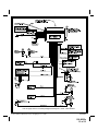
Model APS-25HT
Installation Manual
PROGRAMMABLE FEATURES
RF Programmable Features :
Feature Selection
1) Door Lock O/P
2) Auto Lock
3) Auto Unlock
4) Pass. Locks
5) Arming Method
6) Voltage Sense
7) HJ Start Timer
8) HJ Feature
9) Secured Mode
10) Siren/Horn
11) Horn Chirp
12) Valet Mode
13) Chirp From Tx.
1 Chirp
1 Second Door Locks
Auto Lock On
Auto Unlock On
Passive Door Locks
Passive Arming
Voltage Sense On
Hi-Jack Start 15 Sec.
Hi-Jack Feature On
Secured Mode Active
Siren & Horn
10mS
Custom Code O/R
On
2 Chirps
3.5 Second Door Locks
Auto Lock Off
Auto Unlock Off
Active Door Locks
Active Arming
Voltage Sense Off
Hi-Jack Start 45 Sec
Hi-Jack Feature Off
Secured Mode Passive
Siren Only
16mS
Valet O/R
Off
3 Chirps
1S/1SX2
Horn Only
30mS
Default
1 Second
Auto Lock Off
Auto Unlock Off
Active Locks
Passive Arming
Voltage Sense On
Start Timer 45 Sec.
Hi-Jack Feature Off
Secured Mode Active
Siren & Horn
16mS
Valet O/R
Off
NOTE: When both Passive Arming and Voltage Sensing are selected, you must hardwire the driver’s door pin switch in order
to begin the passive arming sequence.
To program these selectable features;
Action
Turn ignition on
Press and release the valet switch 3 times
Within 3 seconds, turn ignition Off
First
Second
Third
Fourth
Fifth
Sixth
Seventh
Eighth
Nine
Ten
Eleventh
Then On
Press transmitter button 1 to change
Press transmitter button 1 to change
or
Press and release the valet switch once
Press transmitter button 1 to change
or
Press and release the valet switch once
Press transmitter button 1 to change
or
Press and release the valet switch once
Press transmitter button 1 to change
or
Press and release the valet switch once
Press transmitter button 1 to change
or
Press and release the valet switch once
Press transmitter button 1 to change
or
Press and release the valet switch once
Press transmitter button 1 to change
or
Press and release the valet switch once
Press transmitter button 1 to change
or
Press and release the valet switch once
Press Transmitter button 1 to change
or
Press and release the valet switch once
Press transmitter button 1 to change
Press transmitter button 1 to change
or
Press and release the valet switch once
Press transmitter button 1 to change
Press transmitter button 1 to change
System Response
No response
1 Chirp - LED 1 flash
Short chirp, then long chirp
1 chirp = 1 Second door locks
2 chirps = 3.5 Second door locks
3 chirps = 1Sec lock/Dbl. 1S unlock
2 chirps = Auto locks off
1 chirp = Auto locks on
2 chirps = Auto unlock off
1 chirp = Auto unlock on
2 chirp = Active locks
1 chirps = Passive locks
1 chirp = Passive arming
2 chirps = Active arming
1 chirp = Voltage sense feature on
2 chirps = Voltage sense feature off
2 chirp = Hi-Jack start timer 45 seconds
1 chirps = Hi-Jack start timer 15 seconds
2 chirps = Hi-Jack feature off
1 chirp = Hi-Jack feature on
1 chirp = Secure mode active
2 chirps = Secured mode passive
1 chirp = Siren & Horn outputs active
2 chirps = Siren output only
3 chirps = Horn output only
2 chirp = Horn chirp duration 16 mS
3 chirps = Horn chirp duration 30 mS
1 chirp = Horn chirp duration 10 mS
Page 1
Released 3-8-01.
Rev A: Added new web URL 12-2-11
128-6625a
1 of 12
Twelfth
Thirteenth
or
Press and release the valet switch once
Press transmitter button 1 to change
or
Press and release the valet switch once
Press Transmitter button 1 to change
or
Press and release the valet switch once
or
Turn the ignition switch off
2 chirps = Valet override
1 chirp = Custom code override
2 chirps = Chirp delete from transmitter off
1 chirp = Chirp delete from transmitter on
Exit Program Mode
Exit Program Mode
NOTE: Once you enter the feature programming mode, do not allow more than 15 seconds to pass between steps, or the
programming will be terminated.
INSTALLATION OF MAJOR COMPONENTS
Control Module :
Select a mounting location inside the passenger compartment ( up behind the dash ), and secure using the
two screws provided. The control module can also be secured in place using cable ties.
Do not mount the control module in the engine compartment, as it is not waterproof. You should also avoid
mounting the unit directly onto factory installed electronic components. These components may cause RF
interference, which can result in poor transmitter range or intermittent operation.
Siren :
Select a mounting location in the engine compartment that is well protected from access below the
vehicle. Avoid areas near high heat components or moving parts within the engine compartment. To prevent
water retention, the flared end of the siren must be pointed downward when mounted.
Mount the siren to the selected location using the screws and bracket provided.
Hood or Trunk Pin Switch :
A pin switch is included for use in protecting the hood or trunk ( or hatchback ) of the vehicle. The switch
must always be mounted to a grounded, metal surface of the vehicle. It is important to select a location
where water cannot flow or collect, and to avoid all drip gutters on hood and trunk fender walls. Choose
locations that are protected by rubber gaskets when the hood or trunk lid is closed.
The pin switch can be mounted using the bracket provided, or direct mounted by drilling a ¼ " diameter
mounting hole. Keep in mind that when properly mounted, the plunger of the pin switch should depress at
least ¼ " when the hood or trunk lid is closed.
Dash Mounted LED :
A small red LED is included that will serve as a visual indicator of the alarm status. It should be installed in
the dash, located where it can be easily seen from outside the vehicle, yet not be distracting to the driver.
Once a location has been selected, check behind the panel for wire routing access and to confirm the drill
will not damage any existing components as it passes through the panel.
Drill a ¼ " diameter hole, and pass the red and blue wires from the LED through the hole, from the front of
the panel. Firmly press the body of the LED into the hole until fully seated.
Valet Switch :
Select a mounting location for the switch that is easily accessible to the driver of the vehicle. The switch
does not have to be concealed, however, concealing the switch is always recommended, as this provides
an even higher level of security to the vehicle.
The valet switch can be mounted to the lower side of the dash by drilling a ¼ " diameter hole in the selected
location.
Be sure to check behind the dash for adequate clearance for the body of the switch and to confirm that the
drill will not damage any existing components as it passes through the dash. You should also make
certain that the back of the switch is accessible for wiring later in the installation.
Hi-Jack Override/Enable Switch:
Select a cover location for this switch within reach of the driver of the vehicle. This switch can be mounted
behind a soft dash panel, above the driver under the headliner, under the driver's seat. This switch must be
within reach of the operator of the vehicle. The locations mentioned are hidden from view and will be known
only to the vehicle operator yet they allow activation of the switch when necessary.
Page 2
128-6625a
2 of 12
Two Stage Shock Sensor :
Select a solid mounting surface for the shock sensor on the firewall inside the passenger compartment,
and mount the sensor using the two screws provided. The shock sensor can also be secured to any fixed
brace behind the dash using tie straps.
Whichever mounting method is selected, make certain that the sensitivity adjustment is accessible for
use later in the installation.
Wire the sensor according to the installation guide packaged with the sensor.
WIRING THE SYSTEM
Main Wiring Harness :
White Wire : + 12 VDC PULSED PARKING LIGHT OUTPUT ( 15 AMP MAX )
This wire is provided to flash the vehicle’s parking lights. Connect the white wire to the positive side of one
of the vehicle’s parking lights.
Red Fused Wire : + 12 VDC CONSTANT BATTERY SOURCE
This wire supplies power to the control module and, controls the sensitivity of the voltage sensing circuit,
which detects the turning of an interior light when a door is opened. This wire will also detect the switching
on of parking or headlamps, and in many cases will trigger the alarm when a thermostatically controlled
electronic radiator cooling fan switches on.
When installing this system into vehicles with electronic "after fans ", it is recommended you disable the
voltage sense circuit.
In voltage sensing applications, the closer to the battery that the red wire is connected, the less sensitive
the voltage sense circuitry will be. Moving this connection point to the fuse panel will increase the sensitivity, and connecting to the courtesy lamp fuse in the vehicle will provide maximum sensitivity of the voltage
sense circuit.
When hardwiring the control module to pin switches at all entry points, the voltage sense circuit must be
disabled. The control circuit is shipped with selectable feature #6 turned off, and no change is necessary.
If you intend to utilize the voltage sense feature instead of hardwiring, then change selectable feature # 6
to on as described on page 1 of this manual.
Dark Blue Wire : DELAYED 300 mA PULSED OUTPUT / CHANNEL 2
The dark blue wire pulses to ground via an independent RF channel from the keychain transmitter. This is
a transistorized, low current output, and should only be used to drive an external relay coil.
WARNING: Connecting the dark blue wire to the high current switched output of trunk release circuits, and
some remote start trigger inputs, will damage the control module.
In these cases connect the dark blue wire to terminal 86 of the AS - 9256 relay (or equivalent 30 A
automotive relay), and wire the remaining relay contacts to perform the selected function of channel 2.
White w/ Black Trace Wire : POSITIVE OUTPUT TO SIREN
Route this wire through a rubber grommet in the firewall, and to the siren location.
Connect the white / black wire to the positive wire of the siren. Secure the black ground wire of the siren to
chassis ground.
Red/White Wire: + 12 VDC CIRCUIT SUPPLY
See Red Wire above. Connecting the above Red wire completes the connection for the Red/
White wire.
Black Wire : CHASSIS GROUND
Connect this wire to a solid, metal part of the vehicle’s chassis. Do not confuse this wire with the thin black
antenna wire that exits the control module independently.
Yellow Wire : + 12 VDC IGNITION SOURCE
Connect this wire to a source that is live when the key is in the on and crank positions. Be sure that this
source is off when the key is in the off position.
Dark Green Wire : ( - ) Instant Trigger Zone 2
This is an instant on ground trigger wire. It must be connected to the previously installed hood and trunk pin
switches.
Brown Wire : - DOOR TRIGGER
If the vehicle’s courtesy light switches have a ( - ) ground output when the door is opened ( GM and most
Imports ), you must connect this wire to the negative output from one of the door switches.
WARNING : Do not use the brown wire if the vehicle has + 12 volt output type door switches.
(see Purple Wire).
Page 3
128-6625a
3 of 12
Purple Wire : + DOOR TRIGGER
If the vehicle’s door courtesy light switches have a + 12 volt output when the door is opened ( most Fords
and some Imports ), you must connect this wire to the positive output from one of the door switches. In
most cases, the purple wire will only needs to be connected to one door switch, no matter how many doors
the vehicle has.
WARNING : Do not use the purple wire if the vehicle has ground output type door switches. (see Brown Wire).
Orange Wire: 300 mA GROUND OUTPUT WHEN ARMED - N. C. STARTER DISABLE (Optional
Relay Required)
This wire is provided to control the starter cut relay. Connect the orange wire to terminal 86 of the relay.
Connect relay terminal 85 to an ignition wire in the vehicle that is live when the key is in the on and crank
positions, and off when the key is in the off position. ( This is where the yellow wire from the alarm should
be connected ).
Cut the low current starter solenoid wire in the vehicle, and connect one side of the cut wire to relay
terminal 87A. Connect the other side of the cut wire to relay terminal 30.
NOTE: This is a normally closed starter cut arrangement, and when power is removed from the
security system, the starter disable feature will not operate, allowing the vehicle to start.
Audiovox does not recommend using the Orange wire to interrupt anything but the starting
circuit of the vehicle.
3 Pin White Connector:
Dark Green w/ Black Trace Wire : Latching Output / Channel 3
This wire latches to ground via an independent RF channel from the keychain transmitter. This is a transistorized, low current ( 300 mA ) output, and should only be used to drive an external relay coil.
This wire provides an immediate ground signal, and stays at ground for as long as the button(s) on the
keychain transmitter remain pressed.
WARNING ! Connecting this wire to the high current switched output of trunk release circuits will
damage the control module.
Connect this output to terminal 86 of the AS 9256 relay ( or an equivalent 30 Amp automotive relay ), and
wire the remaining relay contacts to perform the selected function of channel 3.
Dark Blue w/Black Trace Wire: Alternate Channel 2 Output (Dbl. Push Required)
This wire is controlled from the transmitter button programmed to the receiver's channel 2. By double pressing
this the transmitter button, this output will become active for 1 second. This is a transistorized, low current
( 300 mA ) output, designed to provide an output only when the transmitter is intentionally operated, such as
is the case with remote start add on modules. If you require more than 300mA drive from this output, you must
drive an external relay coil, and arrange the relays contacts to preform the specified function.
NOTE: Pressing the transmitter button, then immediately pressing and holding it will cause this output to
be active as long as the transmitter button is depressed.
Black w/ White Trace Wire : 300 mA Horn Output
The black w/ white trace wire is provided to beep the vehicle’s horn. This is a transistorized low current output, and
should only be connected to the low current ground output from the vehicle’s horn switch.
If the vehicle uses a + 12 VDC horn switch, then connect the black w/ white trace wire to terminal 86 of the AS 9256
relay ( or an equivalent 30 Amp automotive relay ), and connect relay terminal 85 to a fused + 12 VDC battery source.
Connect relay terminal 87 to the vehicle’s horn switch output, and connect relay terminal 30 to a fused + 12 VDC
battery source.
Two Black wires: Anti Hijack Interrupt circuit
The two black wires connect to the normally open and common contacts of the circuits on board relay. These
wires are designed to interrupt the ignition or fuel pump circuit to cause the vehicle to go through the progressive anti hijack sequence as described in the owners manual. Cut the ignition or electric fuel pump feed wire
at a convenient location in the vehicle. Connect one side of the cut wire to one of these black wires, and
connect the other side of the cut wire to the second black wire.
If the circuit is not being used as a anti hijack unit, these two wires may be used to inhibit the starter solenoid
circuit of the vehicle as these wires will also prevent operation of the vehicle whenever the security system
is armed.
2 Pin Blue Connector : VALET SWITCH
Route the grey and black wires in the 2 pin connector from the valet switch to the control module, and plug
it into the mating blue connector on the side of the module.
2 Pin White Connector : DASH MOUNTED LED
Route the red and blue wires in the 2 pin white connector from the LED to the control module, and plug it
into the mating white connector on the side of the module.
Page 4
128-6625a
4 of 12
2 Pin Red Connector : HI-JACK OVERRIDE
Route the 2 pin red connector from the override switch previously mounted to the mating two pin connector
on the module.
Red & Green 2 Pin White Connector : DOOR LOCK OUTPUTS
These wires will provide a pulsed ground output to the factory door lock control relay. The maximum current
draw through these outputs must not exceed 300 mA.
3 Wire Ground Switched Door Locks
In this application, the red wire provides a ground pulse during arming, or the pulsed ground lock output.
Connect the red wire to the wire that provides a low current ground signal from the factory door lock switch
to the factory door lock control relay.
The green wire provides a ground pulse during disarming, or the pulsed ground unlock output. Connect
the green wire to the wire that provides a low current ground signal from the factory door unlock switch to
the factory door lock control relay.
3 Wire Positive Switched Door Locks
4 Wire Polarity Reversal and
5 Wire Alternating 12 Volt
Door Lock Control Circuits
In these applications, the AS 9159 Door Lock Interface ( or equivalent 30 A automotive relays ) must be
used. Refer to the AUDIOVOX Door Lock Wiring Supplement for proper connection to these types of
circuits.
COMPLETING THE INSTALLATION
Antenna Wire : Be sure to extend the thin black antenna wire to it’s full length, and cable tie into place
where it cannot be damaged. Avoid wrapping this wire around major, high current wire looms.
Adjusting the Shock Sensor :
Be certain to adjust the shock sensor according to the manual packaged with the sensor.
Wire Dressing : Always wrap the alarm wires in convoluted tubing, or with a spiral wrap of electrical tape.
Secure these looms along the routing using cable ties. This will ensure that the alarm wires are not
damaged by falling onto hot or sharp moving surfaces in the vehicle.
Operation : Take a few moments to check off the appropriate option boxes in the owner’s manual, and to
fully explain the operation of the system to your customer.
MODULE UPGRADE CONNECTOR
The 4 pin connector marked, on the wiring diagram, for upgrade tracking module is designed to interface
only with Audiovox upgrade modules. The connector provides data 5 volt reference voltage. The specific
upgrade module has it's own instructions describing the required voltages and how it is to connect to the
host module. Please refer to the instructions packaged with your upgrade module before making any
connections to this port.
NOTE: The unit must be hardwired for trigger method, feature # 6, voltage sense turned off or the unit will
false trigger when the upgrade module activates. Pin assignments for the connector are, Pin1 = +
5 Volts, Pin 2 = Ground, Pin 3 = Data Tx, & Pin 4 = Data Rx.
ADDITIONAL PROGRAMMING INFORMATION
The receiver for the APS-25HJLAD has four receiver channels which can be operated with the remote
transmitter. Receiver channel 1 operates the arming/locking, disarming/unlocking, as well as the panic
feature of the system. Receiver channel 2 operates the channel two outputs (Dark Blue & Blue/Black)
wires of the control module. Receiver channel 3 operates the channel two output (Green/Black) wire of the
control module. Receiver channel 4, when programmed, operates the Anti HiJack feature of the system.
Channel 4, Hijack activation can be operated from the programmed transmitter regardless of the feature
selection of the control module. Please see transmitter programming information found in the
APS-95BT3LA or APS-95BT2LA or APS-95BT2VE programming guides.
Page 5
128-6625a
5 of 12
For technical support go to www.prestigecarsecurity.com or call 1 800 225-6074
© 2011 Audiovox Electronics Corp., Hauppauge, N.Y. 11788
128-6625A
128-6625a
6 of 12
Modelo APS-25HT
Manual de Instalación
CARACTERÍSTICAS PROGRAMABLES
Características programables RF
Selección de característica
1) Cerradura y cerradura abierta
2) Ignición cerradura automática
3) Ignición cerradura abierta automática
4) Bloqueos de puerta
5) El Método armando
6) Detección de voltaje
7) Demora el inicio de antisecuestro
1 chirrido
1 segunda duración
operacional
operacional
bloqueos de puerta pasivos
armado pasivo
deteccione encendido
demora el inicio de
antisecuestro 15 segundos
8) Característica antisecuestro
operacional
9) Antisecuestro mode asegurado
modo asegurado activo
10) La sirena / el bocina
la sirena y el bocina
11) la vehículo bocina chirrido duración 10ms
12) la desactivación manual
el Código personal
13) chirridos controló del transmisor
operacional
2 chirridos
3 chirridos
3.5 segunda duración
1 segundo / 2X 1 Segundo
no operacional
no operacional
bloqueo de puertas activo
armado activo
detección apagado
demora el inicio de
antisecuestro 45 segundos
no operacional
modo asegurado pasivo
la sirena sólo
el bocina sólo
16ms
30ms
simple interruptor valet
no operacional
Preajuste
1 segundo duracion
no operacional
no operacional
bloqueo activo
armado pasivo
encendido
antisecuestro
45 segundos
no operacional
modo asegurado activo
la sirena y el bocina
16ms
simple interruptor valet
no operacional
NOTA: Cuando se seleccionan el armado pasivo y la detección de voltaje, usted debe efectuar una conexión permanente al conmutador de clavija
de la puerta del chófer a fin de iniciar la secuencia de armado pasivo.
Para programar las siguientes características seleccionables:
Primero
Acción
Encienda el mecanismo de encendido
Encienda y apague 3 veces el conmutador de aparcachoes.
Dentro de 3 segundos, apague el mecanismo de encendido
Luego enciéndala
Pulse el botón 1 del transmisor para cambiar
Pulse el botón 1 del transmisor para cambiar
o
Segundo Encienda y apague el conmutador de aparcacoches
Pulse el botón 1 del transmisor para cambiar
o
Tercero Encienda y apague el conmutador de aparcacoches
Pulse el botón 1 del transmisor para cambiar
o
Cuarto
Encienda y apague el conmutador de aparcacoches
Pulse el botón 1 del transmisor para cambiar
o
Quinto
Encienda y apague el conmutador de aparcacoches
Pulse el botón 1 del transmisor para cambiar
o
Sexto
Encienda y apague el conmutador de aparcacoches
Pulse el botón 1 del transmisor para cambiar
Séptimo
o
Encienda y apague el conmutador de aparcacoches
Pulse el botón 1 del transmisor para cambiar
Octavo
Noveno
o
Encienda y apague el conmutador de aparcacoches
Pulse el botón 1 del transmisor para cambiar
o
Encienda y apague el conmutador de aparcacoches
Pulse el botón 1 del transmisor para cambiar
o
Respuesta del sistema
Ninguna respuesta
1 chirrido - LED 1 parpadeará
Chirrido corto, luego chirrido largo
1 chirrido = abra y cierre pulso = 1 secundo
2 chirridos = abra y cierre pulso = 3.5 secundo
3 chirridos = abra pulso = 1 secundo,
y cierre pulso = 2 x 1 secundo
2 chirridos = Bloqueos automáticos apagados
1 chirrido - Bloqueos automáticos encendidos
2 chirridos = Desbloqueo automático apagado
1 chirrido = Desbloqueo automático encendido
2 chirridos = Bloqueos activos
1 chirrido = Bloqueos pasivos
1 chirrido = Armado pasivo
2 chirridos = Armado activo
1 chirrido = Característica de detección de
voltaje encendida
2 chirridos = Característica de detección de
voltaje apagada
2 chirridos - Demora de inicio de
antisecuestro 45 segundos
1 chirrido = Demora de inicio de
antisecuestro 15 segundos
2 chirridos = Característica antisecuestro apagada
1 chirrido = Característica antisecuestro encendida
1 chirrido = Modo asegurado activo
2 chirridos = Modo asegurado pasivo
Página 1
128-6625a
7 of 12
Diez
Once
Doce
Trece
NOTA:
Encienda y apague el conmutador de aparcacoches
1 chirrido = la sirena y el bocina activo
Pulse el botón 1 del transmisor para cambiar
2 chirridos = la sirena sólo activo
Pulse el botón 1 del transmisor para cambiar
3 chirridos = el bocina sólo activo
o
Encienda y apague el conmutador de aparcacoches
2 chirridos = bocina chirrido duración 16 ms
Pulse el botón 1 del transmisor para cambiar
3 chirridos = bocina chirrido duración 30 ms
Pulse el botón 1 del transmisor para cambiar
1 chirrido = bocina chirrido duración 10 ms
o
Encienda y apague el conmutador de aparcacoches
2 chirridos = simple interruptor valet
Pulse el botón 1 del transmisor para cambiar
1 chirrido = el Código desactivación personal
o
Encienda y apague el conmutador de aparcacoches
2 chirridos = chirridos controló del transmisor no
Pulse el botón 1 del transmisor para cambiar
1 chirrido = chirridos controló del transmisor
o
Encienda y apague el conmutador de aparcacoches
Salir del modo de programación
o
Apague el mecanismo de encendido
Salir del modo de programación
Una vez que entre en el modo de programación de características no deje transcurrir más de 15 segundos entre los
pasos, ya que de otra manera la programación se terminará.
INSTALACIÓN DE LOS COMPONENTES PRINCIPALES
Módulo de control:
Seleccione un lugar de montaje dentro del compartimiento de pasajeros (detrás del tablero de instrumentos), y
sujételo usando los dos tornillos provistos. El módulo de control también puede sujetarse en posición con amarres
de cable.
No monte el módulo de control en el compartimiento del motor, ya que no es impermeable. También debe evitar el
montaje de la unidad directamente sobre componentes electrónicos instalados en fábrica. Estos componentes
podrán ocasionar interferencia RF, lo que puede conducir en deficiencias del alcance del transmisor u operación
intermitente.
Sirena:
Seleccione un lugar de montaje en el compartimiento del motor bien protegido contra acceso desde debajo del
vehículo. Evite las áreas cerca de componentes de mucho calor o las piezas móviles dentro del compartimiento del
motor. Para evitar la retención de agua, el extremo abocinado de la sirena ya montada debe apuntar hacia abajo.
Monte la sirena en el lugar seleccionado usando los tornillos y la ménsula provistos.
Conmutador de clavija del capó o baúl
Se incluye un conmutador de clavija para la protección del capó o baúl (o puerta trasera) del vehículo. El conmutador
siempre debe montarse en una superficie metálica puesta a tierra del vehículo. Es importante seleccionar un lugar
donde no pueda fluir ni acumularse agua, y evitar las canaletas de goteo en las paredes de parachoques del capó
y el baúl. Seleccione lugares protegidos por empaquetaduras de goma cuando el capó o baúl está cerrado.
El conmutador de clavija puede montarse usando la ménsula provista, o montarse directamente, taladrando un
agujero de montaje de ¼” de diámetro. Tenga presente que, una vez montado correctamente, el émbolo del
conmutador de clavija debe deprimirse por lo menos ¼” cuando se cierra el capó o la tapa del baúl.
Indicador LED montado en el tablero de instrumentos
Se incluye un pequeño indicador LED rojo que servirá de indicador visual de la situación de alarma. El indicador
LED debe instalarse en el tablero de instrumentos, en un lugar donde sea fácilmente visible desde el exterior del
vehículo, pero que no constituya una distracción para el chofer.
Una vez seleccionado el lugar, inspeccione detrás del panel para averiguar el acceso a la vía de cables y para
confirmar que el taladro no dañará ningún componente existente al atravesar el panel.
Taladre un agujero de ¼” de diámetro y pase los alambres rojo y azul del indicador LED a través del agujero, desde
el frente del panel. Presione firmemente el cuerpo del indicador LED dentro del agujero hasta que haya quedado
plenamente asentado.
Conmutador de aparcacoches
Seleccione un lugar de montaje del conmutador fácilmente accesible para el chofer del vehículo. No es
imprescindible que este conmutador se instale en un lugar oculto; no obstante, siempre se recomienda ocultar el
conmutador, ya que así se confiere un nivel aún mas alto de seguridad al vehículo.
El conmutador de aparcacoches puede montarse en el lado inferior del tablero de instrumentos, taladrando un
agujero de ¼” de diámetro en el lugar seleccionado.
Cerciórese de inspeccionar detrás del tablero de instrumentos para averiguar que hay suficiente espacio para
Página 2
128-6625a
8 of 12
acomodar el cuerpo del conmutador y para confirmar que el taladro no dañará ningún componente existente al
atravesar el tablero de instrumentos. También debe cerciorarse de que haya acceso a la parte trasera del conmutador
para el alambrado más adelante en la instalación.
Conmutador de anulación/habilitación del modo antisecuestro
Seleccione un lugar oculto para este conmutador, al alcance del chofer del vehículo. Este conmutador puede
montarse detrás de un panel blando del tablero de instrumentos, por arriba del chofer debajo del forro de techo o
debajo del asiento del chofer. Este conmutador debe quedar al alcance del operador del vehículo. Los lugares
mencionados no están visibles y sólo serán conocidos por el operador del vehículo, pero permiten la activación del
conmutador cuando sea necesario.
Detector de choques de doble etapa
Seleccione una superficie de montaje sólido para el detector de choques en la pared contrallamas dentro del
compartimiento de pasajeros y monte el detector con los dos tornillos provistos. El detector de choques también
puede sujetarse a cualquier elemento fijo detrás del tablero de instrumentos usando amarres de cable.
Cualquiera que sea el método de montaje seleccionado, cerciórese de que haya acceso al ajuste de sensibilidad
para uso más adelante en la instalación.
Alambre el detector de acuerdo con la guía de instalación incluida con el detector.
ALAMBRADO DEL SISTEMA
Arnés de alambrado principal
Alambre blanco: SALIDA PULSADA DE LUZ DE ESTACIONAMIENTO DE +12 VCC (15 AMP MÁX)
Este alambre se proporciona para hacer parpadear las luces de estacionamiento del vehículo. Conecte el alambre
blanco al lado positivo de una de las luces de estacionamiento del vehículo.
Alambre fusible rojo: FUENTE DE PILA CONSTANTE DE +12 VCC
Este alambre suministra energía al módulo de control y controla la sensibilidad del circuito detector de voltaje, que
detecta cuando se enciende una luz interior al abrirse una puerta. Este alambre también detectará el encendido de
las luces de estacionamiento o faros, y en muchos casos activará la alarma cuando se enciende un ventilador
enfriador de radiador electrónico controlado por termostato.
Al instalar este sistema en vehículos con “posventilador”, se recomienda deshabilitar el circuito detector de voltaje.
En las aplicaciones de detección de voltaje, mientras más cerca de la pila se conecte el alambre rojo, menos
sensibilidad tendrá el circuito detector de voltaje. Si se mueve este punto de conexión al tablero de fusibles se
aumentará la sensibilidad, y si se conecta al fusible de la lámpara de cortesía en el vehículo, se obtendrá la
sensibilidad máxima del circuito detector de voltaje.
Para la conexión permanente del módulo de control a los conmutadores de clavija en todos los puntos de acceso,
el circuito detector de voltaje debe deshabilitarse. El circuito de control se envía con la característica seleccionable
Nº 6 apagada, y no hay necesidad de cambiarla. Si usted tiene intención de utilizar la característica de detección de
voltaje en vez de la conexión permanente, entonces cambie la característica seleccionable Nº 6 a encendida,
según se describe en la página 1 de este manual.
Alambre azul oscuro: SALIDA PULSADA DEMORADA DE 300 mA/CANAL 2
El alambre azul oscuro pulsa a tierra a través de un canal RF independiente desde el transmisor de llavero. Esta
salida es transistorizada de corriente baja y sólo debe usarse para impulsar una bobina de relé externa.
ADVERTENCIA: La conexión del alambre azul oscuro a la salida conmutada de corriente alta de los circuitos de
desenganche de baúl y algunas entradas de activación de encendido remotas dañará el módulo de control.
En estos casos, conecte el alambre azul oscuro al terminal 86 del relé AS-9256 (o relé automotor de 30 A
equivalente), y alambre los demás contactos de relé para realizar la función seleccionada del canal 2.
Alambre blanco con raya negra: SALIDA POSITIVA A LA SIRENA
Tienda este alambre a través de un ojal de goma en la pared contrallamas hasta el lugar de la sirena. Conecte el
alambre blanco/negro al alambre positivo de la sirena. Sujete el alambre de puesta a tierra negro de la sirena a la
puesta a tierra del chasis.
Alambre rojo/blanco: SUMINISTRO DE CIRCUITO DE +12 VCC
Véase las instrucciones para el alambre rojo arriba. La conexión del alambre rojo de arriba completa la
conexión para el alambre rojo/blanco.
Alambre negro: PUESTA A TIERRA DEL CHASIS
Conecte este alambre a una pieza metálica sólida del chasis del vehículo. No confunda este alambre con el
alambre negro delgado de la antena que sale independientemente del módulo de control.
Alambre amarillo: FUENTE DE ENCENDIDO DE +12 VCC
Conecte este alambre a una fuente con corriente cuando la llave está en las posiciones encendida y de arranque.
Cerciórese de que esta fuente esté apagada cuando la llave se encuentra en la posición apagada.
Alambre verde oscuro: Activador instantáneo (-) zona 2
Este cable es un alambre de tierra de encendido instantáneo. Debe conectarse a los conmutadores de capó y baúl
instalados anteriormente.
Alambre marrón: ACTIVADOR (-) DE PUERTAS
Si los conmutadores de las luces de cortesía del vehículo tienen una salida a tierra (-) al abrirse la puerta (GM y la
mayoría de los modelos importados), usted debe conectar este alambre a la salida negativa de uno de los
conmutadores de puerta.
Página 3
128-6625a
9 of 12
ADVERTENCIA: No use el alambre marrón si el vehículo tiene conmutadores de puerta de salida de +12 voltios
(véase Alambre malva).
Alambre malva: ACTIVADOR (+) DE PUERTAS
Si los conmutadores de las luces de cortesía de las puertas del vehículo tienen una salida de +12 voltios al abrirse
la puerta (la mayoría de los modelos Ford y algunos importados), usted debe conectar este alambre a la salida
positiva de uno de los conmutadores de puerta. En la mayoría de los casos, el alambre malva sólo tendrá que
conectarse a un conmutador de puerta, sin importar el número de puertas que tenga el vehículo.
ADVERTENCIA: No use el alambre malva si el vehículo tiene conmutadores de puerta de tipo salida de tierra.
(véase Alambre marrón).
Alambre anaranjado: SALIDA A TIERRA DE 300 mA AL ESTAR ARMADO - DESHABILITACIÓN DE ENCENDIDO
N.C. (Se requiere relé opcional)
Este alambre se proporciona para controlar el relé interruptor de encendido. Conecte el alambre anaranjado al
terminal de relé 86. Conecte el terminal de relé 85 a un alambre de encendido en el vehículo que tiene corriente
cuando la llave se encuentra en las posiciones encendida y de arranque y está apagado cuando la llave se
encuentra en la posición apagada. (Aquí es donde debe conectarse el alambre amarillo de la alarma).
Corte el alambre de solenoide de encendido de baja corriente en el vehículo y conecte un lado del alambre cortado
al terminal de relé 87A. Conecte el otro lado del alambre cortado al terminal de relé 30.
NOTA: Esta configuración da un interruptor de encendido normalmente cerrado, y cuando se quita energía del
sistema de seguridad, la característica de desactivación del encendido no funcionará, permitiendo que
se encienda el vehículo. Audiovox no recomienda usar el alambre anaranjado para interrumpir
nada más que el circuito de encendido del vehículo.
Conector de 3 clavijas
Alambre verde oscuro con negro: SALIDA PULSADA DE 300 mA/CANAL 3
Este alambre pulsa a tierra a través de un canal RF independiente desde el transmisor de llavero. Esta salida es
transistorizada de corriente baja ( 300mA ) y sólo debe usarse para impulsar una bobina de relé externa.
Este alambre manda una senal negativa mientras que el boton o botones del transmisor estén deprimidos.
ADVERTENCIA: La conexión del alambre verde con negro oscuro a la salida de alta corriente del circuito de
desenganche de baúl y algunas entradas de activación de encendido remotas dañará el módulo de control.
En estos casos, conecte el alambre verde con negro oscuro al terminal 86 del relé AS-9256 (o relé automotor de
30 A equivalente), y alambre los demás contactos de relé para realizar la función seleccionada del canal 3.
Alambre Azul oscuro con Negro: Salida alternada de canal 2 (Doble Empujón Requirió)
Este alambre se controla del botón del transmisor programado al canal 2 del receptor. El apretando doble este el
botón del transmisor, este rendimiento se pondrá activo durante 1 segundo. Esta salida es de baja corriente
(300 MA) diseñó para proporcionar una salida cuando el botón del transmisor se opera intencionalmente con
doble empuje. Si usted requiere más de 300mA de corriente, un rele optativo se requiere.
La NOTA: Apretando el botón del transmisor y inmediatamente apretandolo otra vez y sosteniéndolo causarán que
esta salida mantenga activa mientras el boton del transmisor esté deprimido.
Alambre Negro con Blanco: 300 MA Salida de Bocina / Claxon / Pito
Alambre negro con blanco se proporciona para emitir una señal sonora de la bocina del vehículo.
Ésta es una salida de baja corriente y sólo debe ser conectaado al alambre de activación de baja corriente
negativa
de la vocina del vehículo.
Si el vehículo usa +12 voltios para operar la bocina, un rele optativo debe usarse.
Para esta aplicación, conecte el alambre blanco negro a término 86 del 30 amperio rele optativo.
Conect término 85 del reley optativo al + 12 voltio fundió fuente de la batería.
Conect término 87 de la rele optativa a la salida del interuptor de la vocina del vehiculo.
Conect término 30 de la rele optativo al + 12 voltio fundió fuente de la batería.
Dos cables negros: Circuito interruptor contra robo
Los dos cables negros se conectan a los contactos normalmente cerrado y comunes de los circuitos del relé
interno. Estos cables están destinados a interrumpir el encendido del circuito de la bomba de combustible para
que el vehículo pase por la secuencia progresiva antirrobo como se describe en el manual del propietario. Corte
el cable de encendido o de alimentación eléctrica de la bomba de combustible en un lugar conveniente del
vehículo. Conecte un lado del cable cortado a uno de estos cables negros, y el otro lado del mismo al segundo
cable negro. Si no se usa el circuito como unidad antirrobo, estos dos cables pueden usarse para desactivar el
circuito solenoide de arranque del vehículo dado que estos cables impedirán también el funcionamiento del
vehículo siempre que el sistema de seguridad esté activado.
Conector azul de 2 clavijas: CONMUTADOR DE APARCACOCHES
Tienda los alambres gris y negro en el conector de 2 clavijas desde el conmutador de aparcacoches hasta el
módulo de control y enchufe el conector en el conector azul correspondiente en el lado del módulo.
Conector blanco de 2 clavijas: INDICADOR L.E.D. MONTADO EN EL TABLERO DE INSTRUMENTOS
Tienda los alambres rojo y azul en el conector blanco de 2 clavijas del indicador LED hasta el módulo de control
y enchufe el conector en el conector blanco correspondiente en el lado del módulo.
Página 4
128-6625a
10 of 12
Conector rojo de 2 clavijas: ANULACIÓN DE MODO ANTISECUESTRO
Tienda el conector rojo del conmutador de anulación montado anteriormente al conector de dos clavijas
correspondiente en el módulo.
Conector de 4 clavijas: roja, negra, verde y azul. Detector de choque
Este conector blanco de 4 clavijas se usa para conectar el detector de choque previamente instalado. Encamine
los 4 cables, del detector al conector correspondiente del sistema de alarma.
Conector blanco de 2 clavijas roja y verde: SALIDAS DE BLOQUEO DE PUERTA
Estos alambres proporcionarán una salida pulsada a tierra al relé de control de bloqueo de puertas instalado en
fabrica. La corriente máxima a través de estas salidas no debe exceder 300 mA.
Bloqueos de puerta conmutados a tierra de 3 alambres
En esta aplicación, el alambre rojo proporciona un impulso a tierra durante el armado, o la salida pulsada de
bloqueo a tierra. Conecte el alambre rojo al alambre que proporciona una señal de tierra de corriente baja desde
el conmutador de bloqueo de puertas de fábrica hasta el relé de control de bloqueo de fábrica.
El alambre verde proporciona un impulso a tierra durante el desarmado, o la salida pulsada de desbloqueo a
tierra. Conecte el alambre verde al alambre que proporciona una señal de tierra de corriente baja desde el
conmutador de desbloqueo de puertas de fábrica hasta el relé de control de bloqueo de puertas de fábrica.
Circuitos de control de bloqueo de puertas de:
Bloqueos de puerta conmutados positivos de 3 alambres
Inversión de polarización y
12 voltios alternos de 5 alambres
En estas aplicaciones, debe usarse la Interconexión de Bloqueo de Puertas AS 9159 (o relés automotores de 30
A equivalentes). Refiérase al Suplemento de Alambrado de Bloqueo de puertas de AUDIOVOX para la conexión
apropiada a estos tipos de circuitos.
TERMINACIÓN DE LA INSTALACIÓN
Alambre de antena: Cerciórese de extender el alambre negro delgado de la antena su largo completo y de
sujetarlo en posición con amarres de cable donde no puede dañarse. Evite envolver este alambre alrededor de
bobinas de alambres grandes de corriente alta.
Ajuste del detector de choques:
Cerciórese de ajustar el detector de choques de acuerdo con el manual incluido con el detector.
Terminado de alambres: Siempre envuelva los alambres de la alarma en un tubo en espiral, o con una envoltura
helicoidal de cinta eléctrica. Sujete estos grupos a lo largo de la vía de cables usando amarres de cable. De esta
manera se asegurará que los alambres de la alarma no se dañen por haber caído sobre superficies calientes o
móviles en el vehículo.
Operación: Tome unos momentos para marcar las casillas de opciones apropiadas en el manual del propietario
y explicar plenamente la operación del sistema a su cliente.
MODULO CONECTOR PARA RECIBIR DATOS
El conector de 4 pines marcado, en el digrama de cableado, para la coneccion del modulo de siguimiento es
diseñado solamente para interconectar los modulos de Audiovox.
El conectador proporciona datos referidos a 5 voltios de voltaje.
El modulo específico posee sus propias instrucciones que describen los voltajes requeridos y cómo debe
conectarse con el módulo principal.
Por favor siga las instrucciones empaquetadas con su módulo antes de hacer cualquier conexiones a este
puerto.
NOTA: El método del disparador de alarma, característica seleccionable # 6, El sensor de voltaje debe estar
apagado, o la unidad hara un falso disparo cuando el modulo sea activado. Las asignaciones de pines para el
puerto del conector son, Pin1 = + 5 voltios, pin 2 = tierra (negativo), pin 3 = envio de datos, y pin 4 = Recepcion de
datos.
INFORMACIÓN DE PROGRAMACIÓN ADICIONAL
El receptor del modelo APS-25HJLAD tiene cuatro canales receptores que pueden operarse con el transmisor
remoto. El canal receptor 1 opera la alarma/armado, desarmado/desbloqueo así como la característica de
emergencia del sistema. El canal receptor 2 opera el alambre de salida del canal dos (azul oscuro & azul con
negro) El canal receptor 3 opera el alambre de salida del canal dos (verde con negro)
el módulo de control. Cuando está programado, el canal receptor 4 opera la característica antisecuestro del
sistema. El canal 4, activación de la característica antisecuestro, puede operarse desde el transmisor programado
sin importar la selección de características del módulo de control. Sírvase consultar la información de programación
del transmisor contenida en la guía de programación del modelo APS-95BT3LA O APS-95BT2LA O APS-95BT2VE.
Página 5
128-6625a
11 of 12
Para el apoyo técnico va a www.prestigecarsecurity.com o llama 1 800 225-6074
© 2011 Audiovox Electronics Corp., Hauppauge, N.Y. 11788
128-6625a
128-6625a
12 of 12