1
Be sure your appliance is properly installed and
grounded by a qualified technician. Installation,
electrical connections and grounding must comply
with all applicable codes.
! Related Equipment Safety
Remove all tape and packaging before using the
appliance. Destroy the packaging after unpacking
the appliance. Never allow children to play with
packaging material.
Never modify or alter the construction of the
appliance. For example, do not remove leveling
legs, panels, wire covers or anti-tip
brackets/screws.
Do not trap the lead during installation and do not
guide it over sharp edges.
An all pin isolating switch with a contact gap of at
least 3 mm must be installed.
Corner Installation – Figure 2
Observe space requirements of door and door
handle when planning drawers beside the
appliance:
measurement cabinet edge – door panel:
1 7 / 8 ˝ (47 mm)
measurement cabinet edge – door handle edge:
3 11 / 16 ˝ (94 mm)
Observe a minimum opening angle of 90° for corner
installation.
Preparing the Cabinet
Fitted units must be heat-resistant up to 200°F,
adjacent unit fronts up to at least 160°F.
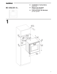
Installation – Figure 3
There must be a ventilation cut-out made in the
intermediate floor of the cabinet. See figure for
dimensions.
IMPORTANT: Do not lift the appliance by the door,
door handle or lower air vent. Lift the appliance by
the installation handles on both sides. Remove
installation handles before installing in cabinet.
Secure furniture which is not fitted to the wall using
a standard fixture.
Insert the appliance in the cabinet and align it
centrally and horizontally.
Install the appliance low enough to allow baking
trays to be easily removed.
Leave an air gap of at least 1 / 4 ˝ (5 mm) between the
appliance and the front of other cabinets.
Cut out the units before fitting the oven. Remove
shavings as they can affect the function of electrical
components.
Secure the appliance with the screws provided.
Electrical Connection
Observe rating plate data for voltage and total
rating.
Attach flexible conduit to the junction box.
Connect the oven lead wires to the junction box
supply wires in proper phase. Only connect in
accordance with the connection diagram.
1.
Connect the red oven wire to the red electrical
supply wire (hot wire).
2.
Connect the black oven wire to the black
electrical supply wire (hot wire).
3.
Connect the white neutral oven wire to the
white neutral (not bare ground) electrical
supply wire.
4.
Connect the bare ground oven wire to the bare
ground electrical supply wire.
If there is no fitted shelf above the oven in the
cabinet, secure the oven against tipping over when
the door is opened. Fit two standard angles 1 / 4 ˝
(5 mm) above the appliance at 17 3 / 4 ˝ (450 mm)
depth inside the cabinet.
Combination with Steam Oven
BS 280/281
The steam oven BS 280/281 is fitted with the
controls on the bottom. Therefore it is particularly
suitable for installation above a Gaggenau series
BO 2.. oven.
The rear of the series BO 2.. ovens has tapered
edges. Guide the water inlet hose and the drainage
hose on the rear left side of the cabinet down to the
connections.
Fit the steam oven first. Follow the installation
instructions for the steam oven.
To facilitate service, the flex conduit must not be
shortened and should be routed to permit
temporary removal of the oven.
Combination with Warming Drawer
WS 2..
NOTE: If the oven is installed and connected as
specified above, it will be completely grounded in
compliance with the National Electrical Code.
Fit the warming drawer first. Follow the installation
instructions for the warming drawer.
3