1
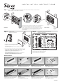
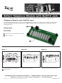
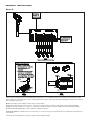
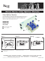
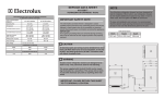
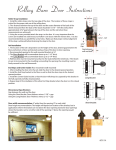
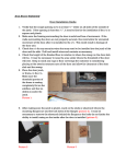
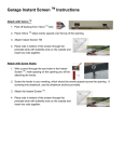
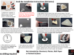
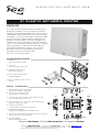
I N S T A L L A T I O N
I N S T R U C T I O N S
9 ” P L A S T I C N E T. M E D I A C E N T E R
ICRESDC9PE
ICC’s new 9” Plastic Net.Media Center is designed to be
installed in a residence; such as small homes, multi-unit
dwellings and retrofitting existing homes and serve as the
central distribution point for voice, data, audio and video
connectivity. Its compact size makes it perfect for smaller
types of structured cabling installations allowing it to fit
in tight and confined areas. The base is designed to fit
between 16” wall studs and offers a variety of mounting
options. It can be installed inside the wall for a professional
clean appearance, or wall mounted if the walls have
already been installed and painted. ICC’s 9” Plastic
Net.Media Center can be configured with any ICC
Net.Media Center connectivity module.
Holds up to 4 mounting modules.
Package Content/Contenido
1. Enclosure 1ea.
Caja (14.25" x 9.00" x 3.625")
1
2. Cover 1ea.
Cubierto (15.00" x 9.40" x 1.00")
3. Installation Instructions 1ea.
Manual de instalacion
4. #10 x 1" Wood Screws 4 pieces
Tornillo de Madera
5. #6-32 x 1" Machine Screw 2 pieces
Tornillos
3
4
2
5
Features / Caracteristicas
A. Light-weight ABS plastic construction
Construcion de plastico ligero ABS
Top
B. Holds up to 4 mounting modules
Soporta hasta cuatro modulos
G
D
Left
Right
B
C. 110 power knockout for an AC power outlet (optional)
Accepta cajas electricas de 110V
E
D. 3 top, 3 bottom, 4 rear, and 2 side cable entry knockouts
Entradas y salidas para cable
D
A
A
E. 4 surface screw mounts
Cuatro agujeros para montar en superficie
F. Extendable mounting tabs
Lenguetas extensibles para montar entre postes
B
C
F
G. Padlock option for additional security (padlock not included)
Opcion para candado de seguridad
H
Bottom
H. Dry wall markings
Marcas de guia para pared
PremiumProducts I ProvenPerformance I CompetitivePrices
Call us: 888-ASK-4-ICC
I
E-mail us: [email protected] I Go on-line: www.icc.com
© Copyright
2008,
ICC are
andregistered
ICC logo are
registered
trade
name and
All rights reserved. 0808
© Copyright 2009,
ICC. ICC
and ICC.
ICC logo
trade
name and
trademark.
All trademark.
rights reserved.
ISO 9001:2000 Registered
I N S T A L L A T I O N
Step 1:
I N S T R U C T I O N S
With the supplied mounting screws, install the enclosure between wall studs or surface mount.
Instalacion de caja entre poste o superficies.
Adjust the enclosure according to the thickness of the drywall/sheetrock.
Use the drywall marking on the side of the enclosure for guidance.
Ajuste la caja dependiendo el grosor del drywall/sheetrock. Utilice las
marcas en los lados de la caja como guia para montar la caja entre
postes y asegurar que el frente de la caja quede al nivel del
drywall/sheetrock
Stud Mount
Step 2:
2
Step 3:
Install the Cover
Instalacion de cubierto
Surface Mount
Install Net.Media Connectivity Modules
Instalacion de modulos
1
1. Secure the top portion of the cover by
sliding the covers hooking mechanism
onto the enclosure.
Ensamble la porcion de arriva del cubierto con la caja
2. Then secure the bottom portion of the cover with the catch
latch located at the bottom center of the enclosure. Install
#6-32 screws to secure the door with the enclosure.
Optional: Use a padlock to restrict access.
Después asegure la porcion de abajo con el cierre de la
caja. Instale los tornillos #6-32.
Opcional: Use un candado para prevenir acceso.
Mount modules vertically or horizontally
Monte modulos vertical o horizontal
Related Products
Premier CAT 5e Data Module
Premier Telephone Module
Premier CAT 6 Data Module
Premier Video Splitter Module
ICRESDPA1C
ICRESVPA1C
ICRESDPB1C
ICRESAV82C
• Exceeds TIA CAT 5e performance standards
• 8-Port bridged telephone with RJ-31X
• Exceeds TIA CAT 6 performance standards
• 1 input x 8 outputs, supports up to 8 locations
• 8-Port, supports up to 8 computers
• 4 incoming lines with 8 extensions per line
• 8-Port, supports up to 8 computers
• 2 GHz, 5-2300 MHz bandwidth
Compact CAT 5e Data Module
Compact Telephone Expansion Module
Compact CAT 6 Data Module
Premier Video Splitter Module
ICRESDPA3C
ICRESVPB3C
ICRESDPB3C
ICRESAV42C
• Exceeds TIA CAT 5e performance standards
• 8-Port bridged telephone
• Exceeds TIA CAT 6 performance standards
• 1 input x 4 outputs, supports up to 4 locations
• 8-Port, supports up to 8 computers
• For an additional 8 extensions per line
• 8-Port, supports up to 8 computers
• 2 GHz, 5-2300 MHz bandwidth
MSR-0463
Residential Cabling Solutions
8-Port Telephone Module with RJ31X Jack
I
N
S
T
A
L
L
A
T
I
O
N
I
N
S
T
R
U
C
T
I
O
N
S
Telephone Module with RJ31X Jack
ICC’s Telephone Module with RJ31X Jack is an 8-port bridged telephone solution. The module offers a 110 IDC input and an expansion jack for additional connectivity. It supports up to 8 telephone outlets for phone, fax, modem devices, and has access up to 4
incoming phone lines.
B
ICRESVPA3C
INCLUDES:
A
A
8-Port Telephone Module with RJ31X Jack, 1 piece
B
Fasteners, 4 pieces
A
ASSEMBLY INSTRUCTIONS
Step 1.
Step 2.
Step 3.
1. Place module horizontally and align fasteners
with the peg board. Make sure the fasteners are
NOT in locked positions.
2. Push the module so that the fasteners goes into
the peg board of the enclosure.
3. Once the module bracket is in the desired location, push the fasteners to their lock position.
CUSTOMER CARE / TECHNICAL SUPPORT •
16800 Edwards Road, Cerritos CA
© Copyright 2007, ICC. ICC and ICC logo are registered trade name and trademark. All rights reserved.
[email protected] / 888-275-4422 (ASK-4-ICC)
90703 • 562-356-3111 • Fax 562-356-3100
MSR-0432-2 rev A
ASSEMBLY INSTRUCTIONS
Step 4.
4. Connect the incoming phone line to the 110 IDC labeled “From Source.” Use a 110 punch down tool to terminate each wire between contact
blades. Identify each outlet cable and connect to 110 block labeled “To Location.” Punch down twisted pairs depending on which lines are desired
to be activated at each location.
NOTE: Line#1 = Blue, Line#2 = Orange, Line#3 = Green, Line#4 = Brown
Example: Each 110-block represents one location. If you want to activate Line#1 at Location#1, simply punch down the twisted pair (White
Blue/Blue) to the first 110-block. If you want to use a 2-line phone (Line#1 & Line#2) at Location#1, simply punch down twisted pairs (White
Blue/Blue & White Orange/Orange) to the first 110-block to support 2-line phone.
WIRE INSTALLATION: For 110 IDC connector, follow the wire color-code and only use the 110 punch-down tool to terminate the wire between the
contact blades.
RJ-45 Jacks: Phone and data lines are wired according to the TIA T-568-A standard.
Residential Cabling Solutions
Deluxe Series Video Splitter Modules
I
N
S
T
A
L
L
A
T
I
O
N
I
N
S
T
R
U
C
T
I
O
N
S
Video Splitter Modules
2 GHz Video Splitters can support up to eight locations, offering a choice of 4, 6, or
8-ports, and are designed for installation in ICC’s Net.Media Centers. The Video
Splitters receive and distribute CATV, antenna, satellite, or modulated video
signals up to eight analog or digital television sets.
B
ICRESAV42L
ICRESAV62L
ICRESAV82L
INCLUDES:
A
2 GHz Video Splitter, 1 piece
B
Fasteners, 4 pieces
A
ASSEMBLY INSTRUCTIONS
Step 1.
Fasteners (4x)
Splitter
Step 2.
Step 3.
2. Push the module so that the fasteners goes into
the peg board of the enclosure.
3. Once module bracket is in the desired location,
push the fasteners to their lock position.
Enclosure
Module Bracket
1. Place module horizontally and align fasteners
with the peg board. Make sure the fasteners are
NOT in locked positions.
CUSTOMER CARE / TECHNICAL SUPPORT •
16800 Edwards Road, Cerritos CA
© Copyright 2006, ICC. ICC and ICC logo are registered trade name and trademark. All rights reserved.
[email protected] / 888-275-4422 (ASK-4-ICC)
90703 • 562-356-3111 • Fax 562-356-3100
MSR-0411-2 REV C
ASSEMBLY INSTRUCTIONS
Step 4.
4. Prepare an incoming coaxial cable and outgoing coaxial cable by using ICC’s coax cable stripper tool (ICACSCSCTV), All-in-One Universal
Compression tool (ICACSCT01U), and F-type compression connectors (ICRDSAV01F for RG-6, and ICRDSAV04F for RG-6 Quad-Shield). Connect
the incoming cable to the “IN” port of the splitter and the outgoing coaxial cables to the “OUT” ports. The “OUT” ports route the video signal to each
location.