1
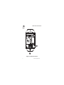
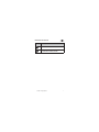
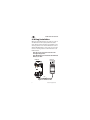
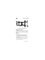
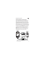
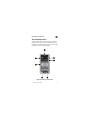
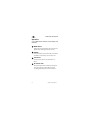
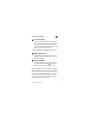
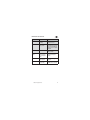
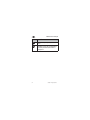
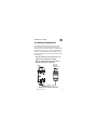
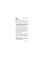
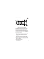
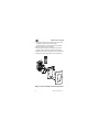
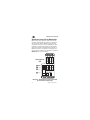
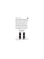
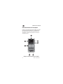
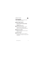
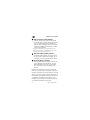
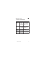
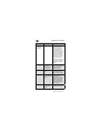
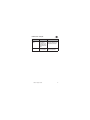
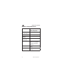
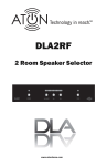
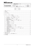
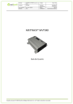
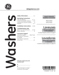
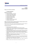
DLATP
TOUCH PAD CONTROLLER
Volume
ATON
www.atonhome.com
DLATP Touch Pad Controller
Safety Information
NOTE: This equipment has been tested and found to comply with the
limits for a Class B digital device, pursuant to part 15 of the FCC Rules.
These limits are designed to provide reasonable protection against
harmful interference in a residential installation. This equipment generates, uses and can radiate radio frequency energy and, if not in-stalled
and used in accordance with the instructions, may cause harmful
interference to radio communications. However, there is no guarantee
that interference will not occur in a particular installation.
If this equipment does cause harmful interference to radio or television
reception, which can be determined by turning the equipment off and
on, the user is encouraged to try to correct the interference by one or
more of the following measures:
• Reorient or relocate the receiving antenna.
• Increase the separation between the equipment and receiver.
• Connect the equipment into an outlet on a circuit different from
that to which the receiver is connected.
• Consult the dealer or an experienced radio/TV technician for help.
CAUTION: Changes or modifications not expressly approved by ATON
could void the user’s authority to operate the equipment
Clean only with a dry soft cloth.
It is important to properly care for your DLATP. Follow these guidelines
to ensure your device is preserved and protected.
• Do not expose the DLATP to rain, liquids or moisture for an
extended period of time.
• Do not expose the DLATP to temperature extremes.
Operating Temperatures & Environments
• Operating Temperature: 32-104°F (0-40°C) Humidity: 0-90%
© 2008 • All rights reserved.
1
DLATP Touch Pad Controller
Precautions
• Always exercise care when operating a system utilizing the DLATP.
• Do not install near any heat sources such as radiators, heat registers, stoves, or other apparatus (including amplifiers) that
produce heat.
• In the unlikely event that smoke, abnormal noise, or strange odor
is present, immediately power the DLA2/4/6 Speaker Level Audio
Router that the DLATP is connected to off. Please report the
problem to your dealer immediately.
• Never attempt to disassemble the DLATP. You will lose any product
warranty on the unit.
Package Contents
•
•
•
•
2
DLATP Touch Pad Controller
Wall Plate/Wall Plate Base
Mounting Screws
Installation Manual
©2008 • All rights reserved.
DLATP Touch Pad Controller
1. Introduction
The DLATP is ATON’s Touch Pad Controller for the
DLA 2/4/6 Speaker Level Audio Router. The DLATP
provides convenient in-wall control as well as volume,
mute and power status from any room of the DLA
system. Control functions include volume up/down,
mute, power and a built-in IR receiver allows for
control of the DLA and connected audio sources. The
DLATP is a true touch pad with no hard buttons and
features an easy-to read LED display and a removable, replaceable graphic film.
Features
• Touch Pad Controller for DLA2/4/6 Speaker Level
Audio Router
• Attractive Back-Lit Touch Surface - No Hard
Buttons
• Simple, Easy-to-Read LED Display Area Provides
Room Status
• Removable, Customizable Graphic Films Available
• Screwless Wall Plates (White, Ivory and Almond)
and Matching Touch Surface Films
• Quick Plug and Play Installation - No PC Software
Programming Required
• Built-In IR Receiver
© 2008 • All rights reserved.
3
DLATP Touch Pad Controller
Front
5
4
6
3
7
1
2
Figure 1.1: DLATP Front Callout
4
©2008 • All rights reserved.
DLATP Touch Pad Controller
Function
1
MUTE Button
2
POWER ON/OFF Button
3
Volume Indicator Bar
4
IR SEND/RECEIVE Indicator
5
Sense Status LED
6
MUTE Indicator LED
7
VOLUME UP/DOWN Buttons
© 2008 • All rights reserved.
5
DLATP Touch Pad Controller
Rear
22
1
Figure 1.2: DLATP Rear Callout
6
©2008 • All rights reserved.
DLATP Touch Pad Controller
Function
1
Flip Lock Connectors for Cat-5
2
Touch Pad Room ID DIP Switches
& IR Receiver Enable/Disable
© 2008 • All rights reserved.
7
DLATP Touch Pad Controller
2. Wiring/Installation
Wiring for the DLATP consists of a single run of Cat-5
wire between the DLA 2/4/6 speaker level audio
router IR Input and the IR Output of the DLATP at the
mounting location. If an external IR Receiver such as
ATON’s AIR5 IR Receiver is to be used, run Cat-5 wire
from the mounting location of the IR Receiver to the
DLATP location.
Note: Do not run Cat-5 wires closer than 12"
from high voltage wires.
Note: Maximum wire run between the DLATP and
DLA 2/4/6 is 350'.
DLA 2/4/6
Room IR Input
DLATP Rear
Cat-5
Figure 2.1: DLATP Pre-Wire
8
©2008 • All rights reserved.
DLATP Touch Pad Controller
Installation
The DLATP is designed to mount in a standard singlegang rough-in box (J Box). Typical mounting height is
56-60" from the floor to the bottom of the frame. This
provides optimum viewing for the largest number of
people.
Note: Do not mount the DLATP in the same
rough-in box as high voltage devices such as
electrical outlets or switches.
After running Cat-5, route the wires from the DLA
2/4/6 into the back of the rough-in box, then connect
them to the appropriate fliplock connectors on the
rear of the DLATP. If using an IR Receiver, strip the
ends of three conductors of the Cat-5 from the IR
receiver and splice them onto the Cat-5 run back to
the DLA. Specific connections are detailed in Chapter
3. Connections.
Once connections are made, mount the DLATP into
the rough-in box using the 2 provided screws. Mount
the Trim Plate Bracket as shown in Figure 2.2, then
snap the Screwless Trim Plate in place.
Make sure that the arrows on both the Trim
Plate Bracket and the Trim Plate are pointed UP.
© 2008 • All rights reserved.
9
DLATP Touch Pad Controller
Rough-In
Box
Screw
Stud
Screw
DLATP
Screw
Cat-5
Screw
Figure 2.2: Installing the DLATP
Changing Overlay Film
The DLATP features available customized Graphic
Ovelay Films that can be changed to fit the décor
of the room in which the touch pad is installed. See
Figure 2.3.
To change films:
1. Remove the wall plate from the front of the
unit. Remove the two screws and wall plate
base. Unsnap and remove plastic frame.
2. Remove the two film bracket screws on the top
frame of the unit.
3. Use the notch located in the upper right-hand
corner to open the touch screen (45° max.).
4. Remove the existing film.
10
©2008 • All rights reserved.
DLATP Touch Pad Controller
5. Place the new film into the frame of the transparent touch screen making sure of the proper
orientation.
6. Close the touch screen.
7. Replace the two film bracket screws. Replace
plastic frame.
8. Replace the wall plate base and screws.
9. Snap wall plate into place.
Figure 2.3: Changing the Overlay Film
© 2008 • All rights reserved.
11
DLATP Touch Pad Controller
3. Connections
Connections for the DLATP consist of:
1. DLA 2/4/6
2. DLATP
3. External IR Receiver (Optional)
DLA 2/4/6 Connections
Simply connect the pre-run Cat-5 wire from the correct IR Input port of the DLA 2/4/6 to the fliplock
connector port on the DLATP as shown in Figure 3.1.
DLA 2/4/6
Room IR Input
DLATP Rear
CAT-5
WIRING COLOR CODE
Figure 3.1: IR INPUT to DLATP Connection
12
©2008 • All rights reserved.
DLATP Touch Pad Controller
External IR Receiver Connections
Use a standard IR Receiver such as ATON’s AIR5 or
AIR6 in areas where a hand-held remote needs to
be pointed somewhere other than at the touch pad.
Typical IR Receiver locations are near a TV or other
equipment such as a Local Source (DVD Player, CD
Player, A/V Receiver, etc.). A Plasma friendly receiver
may be added if flooding occurs. Disable the onboard
IR receiver as shown in Figure 4.3. Use a Cat-5 wire
to extend the IR Receiver’s cable if necessary and
connect the other end to the DLATP as shown in
Figure 3.2. It may also be connected directly to the
fliplock connectors on the rear of the DLATP. Only
three conductors of the Cat-5 will be used.
DLATP Rear
DLA 2/4/6
Room IR Input
AIR5 IR Receiver
Internal Wire Colors
White IR OUT
Black GND
Red+12V
X
Yellow STATUS
(Not Connected)
White Blue
Cat-5
Brown
White Green
Orange
Figure 3.2: External IR Receiver Connection
© 2008 • All rights reserved.
13
DLATP Touch Pad Controller
4. Settings & Operation
DIP Switches
DIP
Switches
1
2
3
4
Figure 4.1: DLATP DIP Switches
Function
14
1
ID 1
2
ID 2
3
ID 3
4
IR Enable/Disable
©2008 • All rights reserved.
DLATP Touch Pad Controller
Room Designation Settings
The DLA 2/4/6 has outputs for 2-6 rooms of audio
depending on the model. The DIP Switch settings
on the DLATP allows each touch pad to be a room’s
designated controller. Simply configure the DIP settings according to room number before installing the
DLATP. The settings are shown on the label on the
back of the touch pad. See Figure 4.2 for details.
DIP
Switches
1
2
3
4
Figure 4.2: DLATP Room DIP Settings
© 2008 • All rights reserved.
15
DLATP Touch Pad Controller
IR Receiver Enable/Disable
A standard IR Receiver is built into the DLATP and
lies behind the touch surface between the MUTE and
IR Recieve indicator displays. This allows IR to be received from Source and Learning IR Remote controls.
Switching the DIP switch #4 setting allows the built-in
IR Receiver to be disabled if desired. This feature is
useful if the built-in IR Receiver is being flooded by a
plasma TV, compact flourescent light or sunlight. The
built-in IR Receiver is enabled by default. See Figure
4.3 for details.
IR Receiver
DIP Switches
OFF
ON
Figure 4.3: IR RECEIVER Enable/Disable
16
©2008 • All rights reserved.
DLATP Touch Pad Controller
Touch Pad Operation
Once the DLATP Touch pad is installed, its intuitive
design allows for easy operation. The following section details the functionality of each part of the touch
pad when in normal operating mode.
5
4
6
3
7
1
2
Figure 4.4: Touch pad Operation
© 2008 • All rights reserved.
17
DLATP Touch Pad Controller
Operation
Consult Figure 4.4 for location of each button and
indicator.
1
MUTE Button
Places the area controlled by the touch pad into
MUTE mode, reducing the volume to zero.
2
POWER
Press and release to turn Room ON or OFF. Press
and Hold for 3 seconds to turn all rooms off.
3
Volume Bar
Shows current Volume level when Room is
active.
4
IR Indicator LED
Illuminates when IR commands are being sent
from the touch pad or when IR commands
are being received by the built-in IR receiver.
18
©2008 • All rights reserved.
DLATP Touch Pad Controller
5
Sense Status LED*
Indicates if Source Equipment is powered ON
with a blue LED. This LED will also blink 3 times
when an All Off command sent by the DLATP
(Press and hold the power button for 3 seconds)
has been received by the DLA2/4/6.
* Requires an ATON PS2 power supply plugged into the sense input
of the DLA2/4/6 and the switched input of an AV Receiver.
6
MUTE Indicator LED
The MUTE Indicator LED illuminates when the
Room has been placed in MUTE from the touchpad, RF or IR Remote.
7
Volume UP/DOWN
Ramps VOLUME UP and DOWN or takes Room
out of Mute. The Volume Bar 3 ramps UP or
DOWN to correspond to the button presses.
After 30 seconds without touch activity, the DLATP’s
LEDs and backlighting will turn off. Press the touch
surface once to wake up and display the current status of the touch pad. If the Room is OFF, the Volume
Bar and MUTE Status indicators will not be illuminated. If the Room is ON, the Volume Bar or MUTE
Status indicators will be illuminated.
© 2008 • All rights reserved.
19
DLATP Touch Pad Controller
5. Troubleshooting
Symptom
Cause
Solution
DLATP does
not power up
1. Wiring installed
incorrectly; or wiring
pinout reversed
Verify wiring pinout .
Correct by re-wiring
fliplock connectors to
Cat-5 cable.
2. Break in Cat-5
between Zone and
“Head-End”
Check end to end
connections with cable
tester or voltmeter.
1. Wiring: Incorrect
wiring between
DLATP and DLA
2/4/6
Verify and correct wiring.
2. IR emitter defective at source
Replace IR emitter.
Intermittent IR
source control
IR flooding
Check to see if ambient
light is shining on built
in IR receiver or in direct
line with plasma TV
noise. If the IR Indicator
is flashing when IR is not
being sent, IR flooding
is indicated. Disable the
built-in IR Receiver. Consider use of an external
IR Receiver.
No audio
1. Loose speaker
wires or bad
connection
Check both ends of
speaker wires to ensure
proper connection.
No control of
IR sources
20
©2008 • All rights reserved.
DLATP Touch Pad Controller
Symptom
Distorted
audio
No Status
Cause
Solution
2. Defective
speaker(s)
Swap with known good
speaker and test.
3. Source(s) not
playing audio
Verify that source(s)
turned ON, playing audio,
etc. Check Tape Monitor
settings on A/V or Stereo
Receiver.
4. Zone is in MUTE
Check MUTE Indicator
LED on DLATP.
1. Source Input
Gain/Volume too
high on Amp/Receiver
Reduce Gain/Volume
settings on Amp/Receiver.
2. Defective/Incompatible speaker
Check for damaged
speaker.
Zone I.D. dip switch
set incorrectly
Check label on rear of
DLATP and set correctly.
© 2008 • All rights reserved.
21
DLATP Touch Pad Controller
Appendix A: Specifications
Display
Backlit Touchscreen with
Overlay
Operating
Temperature
32°- 104°/ 0° C - 40° C
Connections
Fliplock Connectors
Wiring Requirements
Cat-5
Power Requirements
12 VDC @ 50 mA
Dimensions
4.07“ X 1.212“ X 1.775“
103 mm X 30.8 mm X
45.1 mm
Weight
0.182 lbs.
82.6 g
Shipping Weight
0.62 lbs.
281.2 g
22
©2008 • All rights reserved.
Limited Warranty
ATON* warrants to the purchaser/end user (“you”) that the DLATP Touch Pad
Controller is to be free from defects in materials and workmanship for a period of two
(2) years from date of purchase (the “Warranty Period”). This warranty is transferable
to subsequent owners of the product as long as the original proof of purchase is
retained. If you discover a defect in material or workmanship within the Warranty Period, you can obtain warranty service by contacting ATON during the Warranty Period
at (859)-422-7137 or [email protected]. If ATON determines that the product is
in fact defective, ATON shall, at its option, repair or replace the product free of charge
to you.
This warranty shall not apply to equipment (a) not manufactured by ATON, (b) to
equipment which was improperly installed, (c) which was repaired or altered by
persons other than ATON or its authorized representatives or subject to unauthorized
tampering, alteration or modification, (d) damaged due to misuse, negligence, accident, acts of God (including, but not limited to, excess moisture, insects, lightning,
flood, electrical surge, tornado, earthquake, or other catastrophic events beyond
ATON’s control), or (e) subject to improper operation, maintenance or storage or
unreasonable use. The foregoing warranties do not cover reimbursement for labor,
transportation, removal, installation or other expenses which may be incurred in connection with repair or replacement. The foregoing remedies shall be your exclusive
remedies for any breach of warranty.
Further, the foregoing warranty does not extend to equipment sold, but not manufactured by, ATON (“Third Party Products”). With respect to any Third Party Products, the
warranty for such product shall be as provided by the manufacturer of such product,
who will also be responsible for warranty service, and ATON will pass through to you
any transferable warranty actually extended to ATON by the manufacturer.
THE FOREGOING WARRANTIES ARE EXCLUSIVE AND IN LIEU OF ALL OTHER
EXPRESSED AND IMPLIED WARRANTIES. ATON EXPRESSLY DISCLAIMS ALL SUCH
OTHER WARRANTIES, INCLUDING BUT NOT LIMITED TO IMPLIED WARRANTIES OF
MERCHANTABILITY, FITNESS FOR A PARTICULAR PURPOSE AND NON-INFRINGEMENT.
Notwithstanding the above, where applicable, if you qualify as a “consumer” under
the Magnuson-Moss Warranty Act, then you may be entitled to any implied warranties
allowed by law for the Warranty Period. Some states do not allow limitations on how
long an implied Limited Warranty lasts, so the above limitation may not apply to you.
ATTENTION: TO OUR VALUED CONSUMERS
Valid proof of purchase is required for all warranty services. Warranty service
requests made without proof of date of purchase will be denied. Please keep the
original sales receipt for your records and send a copy to request warranty service.
This warranty gives you specific legal rights, and you may also have other rights which
vary from state to state.
* ATON is a division of ELAN Home Systems, LLC.
Tecnología al alcance de todos.™
DLATP
DLATP Control «Touchpad»
Volume
ATON
www.atonhome.com
DLATP Control «Touchpad»
Información de Seguridad
Nota: Este equipo ha sido probado y se ha determinado que cumple
con los límites de un dispositivo digital «Class B», en virtud de la
parte 15 de las reglas de la FCC. Estos límites están diseñados para
proporcionar protección razonable contra interferencia dañina en
una instalación residencial. Este equipo genera, usa y puede irradiar
energía de radiofrecuencia, y si no se instala y se usa de acuerdo con
las instrucciones, puede causar interferencia dañina con las comunicaciones de radio. Sin embargo, no hay garantía que no pueda ocurrir
interferencia en una instalación en particular.
Si este equipo causa interferencia dañina a la recepción de radio o
televisión, lo cual se puede determinar al apagar y encender el equipo,
se recomienda al usuario que trate de corregir la interferencia en una
o más de las siguientes maneras:
• Reoriente o reubique la antena receptora.
• Aumente la separación entre el equipo y el receptor.
• Conecte el equipo en un tomacorriente de un circuito diferente
al cual está conectado el receptor.
• Consulte al distribuidor o a un técnico experimentado de radio o
TV para solicitar ayuda.
PRECAUCIÓN: Los cambios o las modificaciones que Elan Home
Systems que no apruebe explícitamente podrían anular la autoridad
del usuario para operar el equipo.
PRECAUCIÓN: Los cambios o las modificaciones que Elan Home
Systems que no apruebe explícitamente podrían anular la autoridad
del usuario para operar el equipo.
• Límpielo sólo con un paño seco y suave.
• No exponga el DLATP a la lluvia, ni a los líquidos ni a la humedad
por un período prolongado de tiempo.
• No exponga el DLATP a temperaturas extremas.
Operating Temperatures & Environments
• El rango de temperatura del funcionamiento: 32-104°F (0-40°C)
• El rango de humedad: Humidity: 0-90%
26
©2008 • All rights reserved.
DLATP Control «Touchpad»
Precauciones
• Siempre tenga cuidado cuando opere un sistema que utiliza el
DLATP.
• No lo instale cerca de fuentes de calor tales como radiadores,
registros térmicos, estufas ni otros aparatos (inclusive
amplificadores) que produzcan calor.
• En el evento improbable que esté presente el humo, el ruido anor
mal u olor raro, apague el DLA 2/4/6 Enrutador Audio de Nivel
de Altavoz, que está conectado al DLATP, Es importante reportar
el problema inmediatamente a su distribuidor.
• Nunca trate de desmontar el DLATP. Perderá toda garantía sobre
el producto.
Contenidos del paquete:
•
•
•
•
DLATP Control «Touchpad»
Placa empotrada/Base de placa empotrada
Tornillos de montaje
Manual de instalación
© 2008 • All rights reserved.
27
DLATP Control «Touchpad»
1. Introducción
El DLATP de ATON es un Control «Touchpad» [teclado
sensible al tacto] que está designado para el DLA
2/4/6 Enrutador de Audio de Nivel de Altavoz. El
DLATP brinda el control empotrado conveniente,
también muestra el estatus del volumen, del silencio
y de la potencia, de cualquier habitación del sistema
DLA. Las funciones del control incluyen la capacidad
de aumentar/bajar el volumen, de activar el modo
de silencio [«MUTE»] y ajustar la potencia; además
tiene un receptor IR incorporado que le permite el
control del DLA y de las fuentes de audio conectadas. El DLATP es un verdadero «touchpad» que no
tiene teclas duras y tiene una pantalla LED que es
fácil de leer y que tiene una película gráfica movible
y reemplazable.
Detalles
• Control «Touchpad» para el DLA 2/4/6 Enrutador
de Audio de Nivel de Altavoz
• Superficie atractiva sensible al tacto iluminada
por atrás [retroiluminación]
• Pantalla LED sencilla y fácil de leer que muestra
el estatus de audio de las habitaciones
• Películas gráficas movibles personalizadas están
disponibles
• Placas empotradas sin tornillos (de colores
blanco, marfil y almendra) y películas a juego con
superficie sensible al tacto
• Instalación rápido de enchufar-y-tocar – no
programar de software de PC requerido
• Receptor IR incorporado
28
©2008 • All rights reserved.
DLATP Control «Touchpad»
Frente
5
4
6
3
7
1
2
Dibujo 1.1: Esquema de frente de DLATP
© 2008 • All rights reserved.
29
DLATP Control «Touchpad»
Función
30
1
Botón de Silencio [«MUTE»]
2
Botón para Encender/Apagar la Potencia [«POWER»]
3
Barra LED de Indicadora de Volumen
4
Indicador de Enviar/Receptar IR
5
LED de Estatus de Sensibilidad
6
Indicador LED de Silencio [«MUTE»]
7
Botones para Aumentar/Bajar el Volumen
©2008 • All rights reserved.
DLATP Control «Touchpad»
Posterior
22
1
Dibujo 1.2: Esquema Posterior de DLATP
© 2008 • All rights reserved.
31
DLATP Control «Touchpad»
Función
32
1
Conectores tipo «flip-lock» para cable
Cat-5
2
Interruptores DIP de «Touchpad» para
identificar estatus de las habitaciones
y Control para Activar/Desactivar el
Receptor IR
©2008 • All rights reserved.
DLATP Control «Touchpad»
2. Cableado/Instalación
El cableado del DLATP consiste en un solo cable
Cat-5 instalado entre la Entrada del DLA 2/4/6
Enrutador Audio de Nivel de Altavoz y la Salida IR del
DLATP al sitio de montaje. Si utiliza un Receptor IR
externo como el AIR5 Receptor IR de ATON, instale
el cable Cat-5 del sitio de montaje del Receptor IR al
sitio de DLATP.
Nota: No instale los cables Cat-5 cerca de 12
pulgadas de los cables de alto voltaje.
Nota: La longitud máxima del cable entre el
DLAPT y el DLA 2/4/6 es 350 pies.
DLA 2/4/6
Entrada IR
de Habitaciones
DLATP
Vista Posterior
Cat-5
Dibujo 2.1: Pre-cableado de DLATP
© 2008 • All rights reserved.
33
DLATP Control «Touchpad»
Instalación
El DLATP está diseñado para montar en una caja
de empalmes de una banda estándar [«J-box»]. La
altura de montaje típica es 56-60 pulgadas desde el
suelo al fondo del marco. Esto le permite ver en óptimas condiciones para la mayoría de las personas.
Nota: No instale el DLATP en la misma caja de
empalmes que tiene dispositivos de alto voltaje,
como tomas eléctricas o interruptores
Después de instalar el cable Cat-5, pase los cables
del DLA 2/4/6 dentro de la parte de atrás de la caja
de empalmes y conéctelos a los conectores apropiados tipo «flip-lock» en la parte de atrás del DLATP.
Si utiliza un Receptor IR, quite el aislamiento de las
puntas de los tres conductores del cable Cat-5 del
Receptor IR y júntelos al cable Cat-5 que viene del
DLA. Las conexiones específicas están detalladas en
el Capítulo 3. Conexiones.
Después de hacer las conexiones, monte el DLATP
dentro de la caja de empalmes, utilizando los dos
tornillos proporcionados. Monte el Soporte de Placa
de Reborde, como está ilustrado en el Dibujo 2.2, y
coloque la Placa de Reborde Sin Tornillos en su sitio
con un golpe seco.
MAsegúrese que las flechas en el Soporte de
Placa de Reborde y en la Placa de Reborde están
apuntados hacia ARRIBA.
34
©2008 • All rights reserved.
DLATP Control «Touchpad»
Caja
de empalmes
Tornillo
Poste
de madera
Tornillo
DLATP
Tornillo
Cat-5
Tornillo
Dibujo 2.2: Para instalar el DLATP
Para Cambiar la Película Superpuesta
El DLATP tiene unas Películas Gráficas Superpuestas personalizadas que se puede cambiar para
complementar la decoración de la habitación donde
el «Touchpad» está instalado. Consulte al Dibujo 2.3.
Para cambiar las películas:
1. Quite la placa empotrada que está al frente de la
unidad. Destornille los dos tornillos y quite la
base de la placa empotrada. Quite el marco
de plástico.
2. Destornille los dos tornillos del soporte de película
que están en el marco más alto de la unidad.
3. Utilice la muesca que está ubicado en la esquina
derecha más alta para abrir la pantalla del «Touch
pad» (45° máximo).
4. Quite la película existente.
© 2008 • All rights reserved.
35
DLATP Control «Touchpad»
5. Coloque la película nueva dentro del marco de la
pantalla transparente del «Touchpad»,
asegurándose que la orientación está correcta.
6. Cierre la pantalla de «Touchpad».
7. Vuelva a fijar el soporte de película con los dos
tornillos. Vuelva a colocar el marco de plástico.
8. Vuelva a fijar la placa empotrada con sus tornillos.
9. Coloque la placa empotrada con un golpe seco.
Dibujo 2.3: Para Cambiar la Película Superpuesta
36
©2008 • All rights reserved.
DLATP Control «Touchpad»
3. Conexiones
Las conexiones del DLATP consisten en:
1. DLA 2/4/6
2. DLATP
3. Receptor IR Externo (Opcional)
Conexiones de DLA 2/4/6
Conecte simplemente el cable Cat-5 ya instalado del
puerto correcto de la Entrada IR del DLA 2/4/6 al
puerto de los conectores tipo «flip-lock» en el DLATP,
como está ilustrado en el Dibujo 3.1.
DLATP
Vista Posterior
DLA 2/4/6
Entrada IR
de Habitaciones
NARANJA
BLANCO/VERDE
BLANCO/AZUL
MARRÓN
CAT-5
Clave de Colores
de Cableado
Dibujo 3.1: ENTRADA IR a la Conexión del DLATP
© 2008 • All rights reserved.
37
DLATP Control «Touchpad»
Conexiones del Receptor IR Externo
Utilice un Receptor IR estándar como el AIR5 o AIR6
de ATON en las áreas donde se debe apuntar un
control remoto a un aparato aparte del «Touchpad».
Los sitios típicos del Receptor IR están cerca de una
televisión u otro equipo, como una Fuente Local
(Lector de DVDs, Lector de CDs, Receptor A/V, etc.).
Un receptor a prueba de plasma se puede agregar
si ocurre la inundación. Desactive el Receptor IR
que está en uso, como está ilustrado en el Dibujo
4.3. Utilice un cable Cat-5 para extender el cable del
Receptor IR (si es necesario) y conecte la otra punta
al DLATP, como está ilustrado en el Dibujo 3.2. Se
puede conectar directamente a los conectores tipo
«flip-lock» en la parte de atrás del DLATP. Se utilizará
solamente tres de los conductores del cable Cat-5.
DLATP Vista Posterior
DLA 2/4/6
Entrada IR
de Habitaciones
AIR5 Receptor IR
Colores de los cables interiores
Blanco SALIDA IR
Negro TIERRA
Rojo +12V
X
Amarillo ESTATUS
(no conectado)
BLANCO/AZUL
Cat-5
MARRÓN
BLANCO/VERDE
NARANJA
Clave de Colores de Cableado
Dibujo 3.2: Conexión del Receptor IR Externo
38
©2008 • All rights reserved.
DLATP Control «Touchpad»
4. Ajustes y Funcionamiento
Interruptores DIP
Interruptores
DIP
1
2
3
4
Dibujo 4.1: Interruptores DIP del DLATP
Función
1
ID 1
2
ID 2
3
ID 3
4
Activar/Desactivar IR
© 2008 • All rights reserved.
39
DLATP Control «Touchpad»
Ajustes de Selección de Habitación
El DLA 2/4/6 tiene salidas de audio para 2-6 habitaciones, dependiendo del modelo. Los ajustes de
los interruptores DIP del DLATP permite que cada
«Touchpad» pueda ser el control designado de cada
habitación. Simplemente configure los ajustes DIP
según el número de habitación antes de instalar el
DLATP. Se puede ver los ajustes en la etiqueta que
está en la parte posterior del «Touchpad». Consulte al
Dibujo 4.2 para más información.
Interruptores
DIP
1
2
3
4
Dibujo 4.2: DLATP Ajustes de Interruptores DIP
para Destinar las Habitaciones
40
©2008 • All rights reserved.
DLATP Control «Touchpad»
Activar/Desactivar el Receptor IR
Un Receptor IR estándar está incorporado dentro del
DLATP y está situado detrás de la superficie de tacto
entre «MUTE» [Silencio] y la pantalla de indicador de
Receptor IR. Esto permite que la emisión infrarroja [IR] se pueda recibir desde la Fuente y de los
controles remotos de Aprendizaje IR. Si ajusta el
Interruptor DIP #4, esto le permite desactivar el
Receptor IR incorporado, si desea. Este detalle es
útil si la inundación del Receptor IR incorporado
está ocurriendo por una televisión de plasma, por
una luz compacta fluorescente o por la luz del sol. El
Receptor IR incorporado está activado por defecto.
Consulte al Dibujo 4.3 para más información.
Interruptores DIP
de Receptor IR
Apagado
Encendido
Dibujo 4.3: Para Activar/Desactivar el Receptor IR
© 2008 • All rights reserved.
41
DLATP Control «Touchpad»
Funcionamiento del «Touchpad»
Cuando el «Touchpad» haya sido instalado, su diseño
le permitirá operarlo fácilmente. La siguiente sección detalla el funcionamiento de cada parte del
«Touchpad», cuando esté ajustado en el modo de
operación normal.
5
4
6
3
7
1
2
Dibujo 4.4: Funcionamiento del «Touchpad»
42
©2008 • All rights reserved.
DLATP Control «Touchpad»
Funcionamiento
Consulte al Dibujo 4.4 para ver donde se puede
encontrar cada botón e indicador.
1
Botón «MUTE» [Silencio]
Ajusta el área controlada por el «Touchpad»
al modo de silencio, reduciendo el nivel de
volumen a cero.
2
«POWER» [Alimentación]
Oprima y suelte para encender o apagar la
habitación. Oprima y sostenga por tres
segundos para apagar todas las habitaciones.
3
Indicador de Volumen
Muestra el nivel actual de volumen cuando la
habitación esté activa.
4
Indicador IR LED
Se ilumina cuando se envíen las órdenes IR
del «Touchpad» y el Receptor IR incorporado esté
recibiéndolos.
© 2008 • All rights reserved.
43
DLATP Control «Touchpad»
5
LED del Estatus de Sensibilidad*
Indica si el Equipo de Fuente está encendido
con un LED azul. Este LED también parpadeará
3 veces cuando el DLATP haya enviado una
orden de «Todos Apagados» (Oprime y sostenga
el botón de «POWER» por 3 segundos) y el DLA
2/4/6 lo habrá recibido.
* Se requiere una ATON PS2 fuente de alimentación que está
enchufada en la entrada de sensibilidad del DLA 2/4/6 y en la
entrada con interruptores de un Receptor A/V.
6
Indicador LED de «MUTE» [Silencio]
El Indicador LED de «MUTE» se ilumina cuando
se haya puesto la habitación en «MUTE» por el
«Touchpad», o por los controles remotos RF/IR.
7
Aumentar/Baja el Volumen
Funciona para aumentar/bajar el volumen o aju
star la Habitación fuera de «MUTE». La barra
LED del Indicador el Volumen aumenta/baja,
que corresponden con los apretones de los
botones.
Al partir de 30 segundos sin tocarlo, los LEDs del
DLATP y la retroiluminación se apagarán. Oprima la
superficie sensible al tacto nuevamente una vez para
activar y mostrar el estatus actual del «Touchpad». Si
la habitación está apagada, el Indicador de Volumen
y el Indicador de «MUTE» no se iluminarán. Si la
habitación está encendida, el Indicador de Volumen
o el Indicador de «MUTE» se iluminarán.
44
©2008 • All rights reserved.
DLATP Control «Touchpad»
5. Solución de Problemas
Síntoma
Causa
Solución
DLATP no se
enciende
1. Cableado
está instalado
incorrectamente;
o conectores de
cableado están en
reverso.
Revise los conectores de
cableado. Corríjalos por
recablear los conectores
tipo «flip-lock» al cable
Cat-5.
2. Hay rotura en
cable Cat-5 entre la
Zona y el aparato
de control central
[«Head-End»].
Revise las conexiones
punta a punta por un
probador de cables o un
voltímetro.
1. Cableado:
Cableado incorrecto
entre DLATP y DLA
2/4/6.
Verifique y corrija el
cableado.
2. Emisor IR está
defectuoso en la
fuente.
Reemplace el Emisor IR.
Falta de
control de
Fuentes IR
© 2008 • All rights reserved.
45
DLATP Control «Touchpad»
Síntoma
Causa
Solución
Inconsistencia
del control de
la fuente IR
Inundación de IR
Verifique si le da la luz
del medio ambiente
sobre el Receptor IR
incorporado o está en
una línea directa con el
ruido de la televisión de
plasma. Si el Indicador
IR está parpadeando
cuando no se envíe una
señal IR, la inundación
de IR está indicada.
Desactive el Receptor IR
incorporado. Piense en
utilizar un Receptor IR
externo.
No hay audio
1. Los cables de
altavoz están
sueltos o tiene una
conexión mala
Revise las dos puntas
de los cables de altavoz
para asegurar una
conexión correcta.
2. Altavoces defectuosos
Cambie por altavoces
ya reconocidos por su
buena calidad y pruebe.
3. Fuente(s) no
está(n) produciendo
el audio
Verifique que la(s)
fuente(s) está(n)
encendida(s), y está(n)
ajustada(s) para tocar
audio, etc. Revise los
ajustes del Monitor de
Cinta en el Receptor de
A/V o Estéreo.
4. La Zona está en
el modo «MUTE»
[Silencio]
Revise el Indicador LED
de «MUTE» en el DLATP.
46
©2008 • All rights reserved.
DLATP Control «Touchpad»
Síntoma
Causa
Solución
Distorsión del
Audio
1. La Entrada de
Fuente Ganancia/Volumen está
demasiada alta en
el Amplificador/Receptor
Reduzca los ajustes de
Ganancia/Volumen en el
Amplificador/Receptor.
2. Altavoz defectuoso/ incompatible
Revise para ver si el
altavoz está dañado.
© 2008 • All rights reserved.
47
DLATP Control «Touchpad»
Apéndice A: Especificaciones
Visualización
Pantalla retroiluminada sensible al tacto con
película sobrepuesta
Temperatura de
Funcionamiento
32°- 104°/ 0° C - 40° C
Conexiones
Conectores tipo «flip-lock»
Requisitos de
Cableado
Cat-5
Requisitos de
Alimentación
12 VDC @ 50 mA
Dimensiones
4.07 pulgadas X 1.212 pulgadas X 1.775 pulgadas
103 mm X 30.8 mm X
45.1 mm
Peso
0.182 libras
82.6 g
Peso de envío
0.62 libras
281.2 g
48
©2008 • All rights reserved.
Garantía limitada
ATON* garantiza al comprador/usuario final («usted») que el DLATP estará libre de
todo defecto de material y mano de obra por un período de dos (2) años a partir de
la fecha de compra («Período de Garantía»). Esta garantía se puede transferir a los
propietarios subsiguientes del producto con tal que el comprobante de venta original
haya sido retenido. Si usted descubre un defecto de material o mano de obra durante
el Período de Garantía, puede obtener servicio de garantía al notificar a ATON durante el Período de Garantía al teléfono (859) 422-7131 o a la dirección electrónica:
[email protected]. Si ATON determina que el producto está defectuoso, ATON, a
opción suya, reparará o reemplazará el producto sin costo alguno para usted.
Esta garantía no se aplica si el equipo (a) no fue fabricado por ATON, (b) fue instalado
incorrectamente, (c) fue reparado o cambiado por otras personas no autorizadas por
ATON o estuvo sujeto a modificaciones no autorizadas, (d) está dañado debido a mal
uso, negligencia, accidentes, fenómenos de la naturaleza (incluyendo pero sin limitarse a humedad excesiva, insectos, relámpagos, inundaciones, sobrecargas eléctricas, tornados, terremotos u otros eventos catastróficos que sobrepasan el control de
ATON) o (e) estuvo sujeto a funcionamiento incorrecto, mantenimiento o almacenaje,
o está dañado por uso impropio. Las garantías precedentes no cubren reembolsos
por mano de obra, transporte, remoción, instalación u otros cargos que puedan ser
incurridos relacionados a reparación o reemplazo. Lasá restituciones precedentes
serán sus restituciones exclusivas por incumplimiento alguno de garantía.
Además, la garantía precedente no se extiende a equipo vendido pero no fabricado
por ATON («Productos de Terceros»). Con respecto a algunos Productos de Terceros, la
garantía de tal producto proveerá por el fabricante de lo mismo, quien también será
responsable del servicio de garantía, y ATON le trasferirá a usted alguna garantía
transferible que haya sido extendida a ATON por el fabricante.
LAS GARANTÍAS PRECEDENTES SON EXCLUSIVAS Y REEMPLAZAN TODA OTRA
GARANTÍA EXPRESA O IMPLÍCITA. ATON EXPLÍCITAMENTE NO RECONOCE NINGUNA
OTRA GARANTÍA, INCLUYENDO PERO SIN LIMITARSE A GARANTÍAS IMPLÍCITAS DE
COMERCIABILIDAD, APTITUD PARA UN OBJETIVO PARTICULAR Y NO INFRACCIÓN.
No obstante, donde aplicable, si usted tiene derecho como «consumidor» bajo el
Acto Magnuson-Moss Warranty, por tanto pueda tener derecho a cualquier garantía
implícita que la ley permite durante el Período de Garantía. Algunos estados no
permiten limitaciones de duración de Garantías Limitadas implícitas, por tanto existe
la posibilidad que la limitación más arriba no concierna a usted.
AVISO: A NUESTROS CONSUMIDORES VALIOSOS:
Se requiere un comprobante de venta válido para todo servicio de garantía. Si usted
pide servicio de garantía sin comprobante de la fecha de compra, se rechazará la
petición. Favor de guardar el recibo de venta original en sus archivos y envíe una
copia del mismo para pedir servicio de garantía.
Esta garantía le proporciona derechos legales específicos y usted podría tener otros
derechos que pueden variar de estado a estado.
*ATON es una división de ELAN Home Systems, LLC.
P/N 9900910 REV:A
INSTR, INSTL, DLATP KEYPAD
LINEAR P/N 9900910 REV:A
INK: BLACK
MATERIAL: 60 LB WHITE COATED PAPER
PAGES: 52 PAGES
SCALE: 1-1
SIZE: 6.000 X 4.500, TOL: +/- .040
FOLDING: ALBUM FOLD CENTER STAPLE
FOLD TO 3.000 X 4.500
NOTE: ARTWORK CREATED BY ELAN HOME
SYSTEMS
MANUAL MUST BE RoHS COMPLIANT