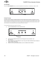
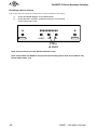
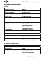
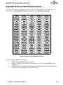
1
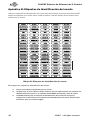
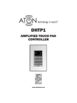
DLA2RF
2 Room Speaker Selector
www.atonhome.com
DLA2RF 2 Room Speaker Selector
Safety Information
NOTE: This equipment has been tested and found to comply with the limits for a Class B digital device, pursuant to part 15 of the
FCC Rules. These limits are designed to provide reasonable protection against harmful interference in a residential installation.
This equipment generates, uses and can radiate radio frequency energy and, if not in-stalled and used in accordance with the
instructions, may cause harmful interference to radio communications. However, there is no guarantee that interference will not
occur in a particular installation.
If this equipment does cause harmful interference to radio or television reception, which can be determined by turning the
equipment off and on, the user is encouraged to try to correct the interference by one or more of the following measures:
•
•
•
•
Reorient or relocate the receiving antenna.
Increase the separation between the equipment and receiver.
Connect the equipment into an outlet on a circuit different from that to which the receiver is connected.
Consult the dealer or an experienced radio/TV technician for help.
CAUTION: Changes or modifications not expressly approved by Elan Home Systems could void the user’s authority to operate the
equipment
DLA2RF Power Source
The source of DLA2RF power is the 12VDC wall transformer. A DC-IN jack connects the 12 VDC adapter with the DLA2RF chassis
to provide power for the unit. Protect the power supply cord from being walked on or pinched, particularly at plugs, outlets and
the point where they exit from the apparatus.
Severe personal injury and equipment damage can result by not following proper procedures. Use only the 12VDC adapter
designated for the DLA2RF.
Caring For the DLA2RF
Clean only with a dry soft cloth.
It is important to properly care for your DLA2RF Speaker Selector. Follow these guidelines to ensure your device is preserved and
protected.
•
•
•
Do not expose the DLA2RF to rain, liquids or moisture for an extended period of time.
Do not expose the DLA2RF to temperature extremes.
Do not place any objects on top of the DLA2RF to prevent chassis damage.
Operating Temperatures & Environments
•
•
Operating Temperature: 32-104°F (0-40° C)
Humidity: 0-90%
Precautions
•
•
•
•
•
•
•
Always exercise care when operating the DLA2RF Speaker Selector.
Do not apply excessive amplification.
ATON strongly recommends that you do not add more speakers than recommended.
Do not install near any heat sources such as radiators, heat registers, stoves, or other apparatus (including
amplifiers) that produce heat.
DO NOT use any 12 VDC adapter other than the one provided with the DLA2RF.
In the unlikely event that smoke, abnormal noise, or strange odor is present, immediately power the DLA2RF
off. Please report the problem to your dealer immediately.
Never attempt to disassemble the DLA2RF. You will lose any product warranty on the unit.
Amplifier Input 125 Watts per Channel Max
Package Contents
DLA2RF Speaker Selector
RF Remote Control
RF Receiver
12 VDC Power Adapter
Room Identification Labels
User/Installation Manual
© 2007 • All rights reserved.
1
DLA2RF 2 Room Speaker Selector
Contents
Safety Information ...................................................................... 1
1. Introduction .............................................................................. 3
Features ........................................................................................
ATON DLA2/4/6 Accessories ......................................................
Front Panel ...................................................................................
Rear Panel ....................................................................................
4
4
5
6
2. System Design Overview ...................................................... 7
Standard Audio/Video or Stereo Receiver ................................. 7
Zone 2 Output of an A/V or Stereo Receiver ............................. 8
External Amplifier ......................................................................... 9
3. Connections ........................................................................... 11
AMPLIFIER INPUT....................................................................... 11
SPEAKER OUTPUTS .................................................................... 12
IR EMITTER OUTPUTS ................................................................ 12
ATON PORT/RF Receiver ........................................................... 13
PWR IN Connection ................................................................... 13
4. Settings & Operation .......................................................... 14
Volume Settings ........................................................................ 14
Receiver/Amplfier Volume Settings ..................................... 14
Volume Status Bar .................................................................. 14
Room Volume Adjustment ...................................................... 15
ALL ON/OFF ................................................................................ 16
Default Volume ........................................................................... 16
Scene Presets ..............................................................................17
Setting a Scene ........................................................................17
Recalling a Scene Preset........................................................ 18
RF Remote Control ..................................................................... 19
5. Troubleshooting ..................................................................... 20
Appendix A: Specifications .................................................... 22
Appendix B: Room Identification Labels ........................... 23
Limited Warranty.......................................................... Back Page
2
©2007 • All rights reserved.
DLA2RF 2 Room Speaker Selector
1. Introduction
A Simple Concept Reaches New Heights
The concept is simple and has been around for years - a device that allows you to connect extra
speakers to your existing A/V or stereo receiver. Push a button - your speakers come on. Push it
again - they go off. Turn a knob, and the volume goes up or down. Great concept. Good exercise,
too - especially when your system is located downstairs or on the other side of the house. Introducing DLA2RF Intelligent Speaker Selectors - the most significant advancement in the history
of speaker selectors!
Sit Back and Relax
Now you don’t have to take a walk before you can sit back, relax and enjoy your music. DLA2RF
Intelligent Speaker Selectors are RF-controllable. Turn music on or off with ease. Adjust the
volume in every room, independently, without having to go back to the equipment location.
Patent-Pending Intelligence & Performance
No other speaker selector available today is as smart! With its patent-pending design, the
DLA2RF’s pre-configured settings ensures that all speakers receive maximum power at all
times, and that your receiver/amplifier isn’t operating below its nominal impedance, which can
cause some very undesirable side effects.
Sound Scenes
DLA2RF even lets you create Sound Scenes around your home. Use DLA2RF’s discrete RF commands to turn on groups of rooms - or every room. Kid’s room too loud? Turn the volume down
in their room instantly from the den. At bedtime, turn off the audio throughout the entire house.
A Simple & Affordable Solution
DLA2RF connects directly to your stereo receiver or amplifier, making it the affordable way to
add 2 more rooms of music to your system. The DLA2RF RF receiver located in the equipment
room is the only thing you’ll need to realize all these remarkable benefits and revel in the enjoyment of RF-controlled music throughout your home.
Figure 1-1 Front Panel
© 2007 • All rights reserved.
3
DLA2RF 2 Room Speaker Selector
Features
•
DLA (Dynamic Level Adjustment) Technology delivers maximum
adjustable volume levels to each room while protecting your
amplifier from damage (patent-pending).
•
ATON™ RF remote (included) controls volume levels independently for each room from inside or outside your home
(up to 200 ft. range)
•
Adds up to 2 pairs of speakers to your home theater/stereo
receiver or amplifier.
•
Programmable “Scene” command for one-touch recall of your
favorite system settings.
•
One-touch “All On” command turns audio on in all rooms.
•
One-touch “All Off” command turns audio off in all rooms.
•
Room Identification Labels with adhesive backing included for
easy Front Panel Room Identification
•
Easy Install Guide included for quick setup
•
1 Year Limited Warranty
ATON DLA2RF Accessories
DLA2RM
RF Remote
PS3
Replacement 12VDC/2.1A Power Supply
Storm Series Speakers
In-Wall, In-Ceiling, Outdoor &
Home Theater Speakers
Note: For more information and purchase options, visit our website at:
www.atonhome.com.
4
©2007 • All rights reserved.
DLA2RF 2 Room Speaker Selector
Front Panel
The front panel of the DLA2RF has five selector buttons to access rooms and control power and
volume states. Blue LEDs display Volume level and Room On status, while red LEDs show that a
room is selected for adjustment. Figure 1-2 and Table 1-1 provide descriptions and locations of
Front Panel controls and indicators.
2
1
3
ROOM 2
ROOM 1
4
5
6
7
8
9
4
Figure 1-2: DLA2RF Front Panel
Indicator/Button
Function
LED
1
Room 1 Indicator LED
Room 1 ON - Selected
Room 1 ON - NOT Selected
Room 1 OFF
Room 1 Muted
Red
Blue
No LED
Blue (Blinking)
2
Volume Indicator
Shows Volume Level for Selected Room- Level 1 to 11
Blue
3
Room 2 Indicator LED
Room 2 ON - Selected
Room 2 ON - NOT Selected
Room 2 OFF
Room 2 Muted
Red
Blue
No LED
Blue (Blinking)
4
Room Label Location
Place Label to Identify
Rooms
5
Room 1 Select
Selects Room 1 for Adjustment
Turns Room 1 OFF if Currently ON or Selected
6
All ON/All OFF Button
Turns all Rooms ON or OFF
7
Volume -
Decreases Volume of
Selected Room by One
Step-Press & Hold to Ramp
Volume Down
8
Volume +
Increases Volume of Selected Room by One Step-Press
& Hold to Ramp Volume
Down
© 2007 • All rights reserved.
5
DLA2RF 2 Room Speaker Selector
9
Indicator/Button
Function
LED
Room 2 Select
Selects Room 2 for Adjustment
Turns Room 2 OFF if Currently ON or Selected
Table 1-1: Front Panel Indicators/Buttons
Rear Panel
The Rear Panel of the DLA2RF has connections for Power, Amplifier Input, the RF Receiver
(ATON Port), IR Emitter Outputs and Speaker Outputs. Figure 1-3 and Table 1-2 provide description and location of Rear Panel connections.
PATENT
PENDING
AMPLIFIER
INPUT
PWR IN
ATON
PORT
IR EMITTER
OUTPUTS
12VDC / 2.1A
CLASS 2 WIRING
1
2
1
3
4
5
6
Figure 1-3 : DLA2RF Rear Panel
Conector
Function
1
12 VDC Power Connector
Connector for +12VDC/ 2.1A Power
Transformer (PS3)
2
Amplifier/Receiver Input
4-position Fliplock Connector for
16 Gauge, 4 Conductor (16/4 AWG)
Speaker Leads From Amplifier or A/V
Receiver Speaker Outputs
•125 Watts per Channel Max
3
ATON Port
Connects to RF Receiver
4
IR Emitter Outputs
3.5mm Mono Mini Jack Connectors
for Use With ATON IR Emitters (Future
Use)
5
Room 1 Speaker Output
4-position Fliplock Connector for
16 Gauge, 4 Conductor (16/4 AWG)
Speaker Leads to Room 1 Speakers
6
Room 2 Speaker Output
4-position Fliplock Connector for
16 Gauge, 4 Conductor (16/4 AWG)
Speaker Leads to Room 2 Speakers
Table 1-2: Rear Panel Connectors
6
©2007 • All rights reserved.
DLA2RF 2 Room Speaker Selector
2. System Design Overview
There are three typical system applications when installing the DLA2RF:
1.
2.
3.
Standard A/V or Stereo Receiver
Zone 2 Output of an A/V Receiver
External Amplifier
Standard Audio/Video or Stereo Receiver
Most A/V Receivers and Stereo Receivers have two sets of Main Speaker Outputs (typically
labelled “A” and “B”. While it is certainly possible to connect the DLA2RF to the “A” outputs, it
is much more useful to connect the “A” outputs to the main speakers (stereo or surround) in
the room in which the receiver is located and connect the “B” outputs to the DLA2RF in order
to expand the audio system to additional areas. Figure 2-1 shows the “B” speaker outputs of
an A/V receiver connected to to the AMPLIFIER INPUT of the DLA2RF. A pair of speakers are
connected to the DLA2RF’s Room 1 Speaker Outputs, while an additional pair of speakers is
connected to the Room 2 Speaker Outputs. The RF RECEIVER BASE is connected to the ATON
PORT. This application allows the A/V receiver’s speakers to play in the main listening area,
while two additional pairs of speakers play in other areas of the home-each controlled by the RF
remote included with the DLA2RF. This is a single-source application: all areas of the house will
play the same audio source, but with separately controlled volume.
Note: For best audio quality, ATON recommends that Surround Sound and/or DSP modes
(Concert, Hall, Jazz, etc.) be disabled prior to playing audio through the DLA2RF.
RF
Base
PS3
POWER
SUPPLY
AMPLIFIER
INPUT
PATENT
PENDING
ATON
PORT
PWR IN
IR EMITTER
OUTPUTS
12VDC / 2.1A
CLASS 2 WIRING
1
Speaker
Cables
Speaker
Cables
R
L
R
L
+
-
A
B
A/V Reciever
Speaker Outputs
Room 1
Speakers
Room 2
Speakers
Figure 2-1: DLA2RF w/ A/V Receiver Output B Overview
© 2007 • All rights reserved.
7
DLA2RF 2 Room Speaker Selector
Zone 2 Output of an A/V or Stereo Receiver
Certain A/V Receivers and Stereo Receivers have a Zone 2 feature that allows them to play a
seperate source to a second zone. Figure 2-2 shows the Zone 2 speaker outputs of an A/V
receiver connected to to the AMPLIFIER INPUT of the DLA2RF. Like the previous example, a pair
of speakers are connected to the DLA2RF’s Room 1 Speaker Outputs, while an additional pair
of speakers is connected to the Room 2 Speaker Outputs. The RF RECEIVER BASE is connected
to the ATON PORT. This application allows the A/V receiver’s Main speakers to play in the room
in which the receiver is located, while two additional pairs of speakers play in other areas of
the home-each controlled by the RF remote included with the DLA2RF. This is a multi-source
application: the Main speakers may play one source, while Zone 2 (the DLA2RF loactions) plays
a different source.
Note: Set the Zone 2 volume level to the point where it achieves the maximum listenable
level (prior to distortion). The DLA2RF’s volume level will adjust up to this maximum level.
RF
Base
PS3
POWER
SUPPLY
AMPLIFIER
INPUT
PATENT
PENDING
ATON
PORT
PWR IN
IR EMITTER
OUTPUTS
12VDC / 2.1A
CLASS 2 WIRING
1
Speaker
Cables
Speaker
Cables
L
R
L
R
+
-
ZONE 1
ZONE 2
A/V Reciever
Zone 2
Speaker Outputs
Room 1
Speakers
Room 2
Speakers
Figure 2-2: A/V Receiver Zone 2 Application
8
©2007 • All rights reserved.
DLA2RF 2 Room Speaker Selector
External Amplifier
Some systems utilize an external amplifier for speakers that are connected to the DLA2RF. In
A/V receiver or stereo receiver applications, a line-level output (Tape Loop, Monitor Out, etc.) is
connected to the external amplifier (See Figure 2-3). In a Pre-Amp/Processor-based system, the
Pre-Amp is connected to the external amplifier as shown in Figure 2-4.
RF
Base
PS3
POWER
SUPPLY
DLA2RF
AMPLIFIER
INPUT
PATENT
PENDING
ATON
PORT
PWR IN
IR EMITTER
OUTPUTS
12VDC / 2.1A
CLASS 2 WIRING
1
Speaker
Cables
Speaker
Cables
+
L
-
+
R
Line-Level
Inputs
L
R
Speaker Outputs
Amplifier
A/V Receiver
RCA
Interconnect
Cables
Room 1
Speakers
Speaker Outputs
L
+
OUT
R
-
-
Room 2
Speakers
+
L
R
IN
TAPE
LOOP
Speaker
Cables
Main
Speakers
Figure 2-3: External Amplifier - A/V Receiver Tape Loop Application
© 2007 • All rights reserved.
9
DLA2RF 2 Room Speaker Selector
RF
Base
PS3
POWER
SUPPLY
DLA2RF
AMPLIFIER
INPUT
PATENT
PENDING
ATON
PORT
PWR IN
IR EMITTER
OUTPUTS
12VDC / 2.1A
CLASS 2 WIRING
1
Speaker
Cables
+
Speaker
Cables
L
-
+
R
Line-Level
Inputs
L
R
Speaker Outputs
Amplifier
RCA
Interconnect
Cables
Room 1
Speakers
Room 2
Speakers
L
R
Line-Level
Outputs
Pre-Amp/Processor
Figure 2-4: Processor/Pre-Amp - Amplifier Application
10
©2007 • All rights reserved.
DLA2RF 2 Room Speaker Selector
3. Connections
AMPLIFIER INPUT
Use 16 AWG stranded copper speaker wire to connect from a speaker level output of an A/V
receiver, stereo receiver, or amplifer. Turn power for the output device OFF before making connections.
To make connections:
1.
2.
3.
4.
5.
Cut the ends of the wire to length, allowing some free play (about 6 inches
of slack) to allow for movement when physically connecting the wire.
Using wire strippers, remove 3/8 inch of insulation, then twist the wire to
ensure that no stray strands are evident.
Define positive (+) and negative (-) at the amplifier end and the DLA2RF
end of the wire run and use the same conductor on each end.
Lift up each flip-lock connector until it is locked in the up position.
Place the bare lead from each speaker wire from the receiver/amplifier
into the holes of the Amplifier Inputs terminal of the DLA2RF, maintaining
the polarity of each lead (+ to +, - to -).
Note: To avoid damage to the receiver/amplifier, DO NOT allow speaker leads to touch
each other.
DLA2RF
AMPLIFIER
INPUT
125 Watts
per Channel
Max
CLASS 2 WIRING
Speaker
Cables
R
L
R
L
+
-
A
B
Receiver/Amplifier
Output
Figure 3-1: Receiver/Amplifier Output to DLA2RF Amplifier Input
© 2007 • All rights reserved.
11
DLA2RF 2 Room Speaker Selector
Important Note:
Speaker Impedance must match receiver/amplifier impedance rating! If the
receiver/amplifier is rated at 8 Ohms minimum impedance, 8 Ohm speakers
must be used. If the receiver/amplifier is rated at 4 Ohms minimum impedance,
4 Ohm speakers may be used. DO NOT use speakers rated BELOW 8 Ohms
with an amplifier rated at 8 Ohms minimum impedance! It is permissable to
use higher rated speakers with a lower impedance-rated amplifier (Example: 8
Ohm speakers may be used with a receiver/amplifier that is rated at 4 Ohms
minimum impedance).
SPEAKER OUTPUTS
Follow the procedures outlined in the previous section to connect the Speaker Outputs to the
Room 1 and Room 2 speakers. Make sure to match the impedance of the speakers and amplifiers as noted.
DLA2RF
1
Speaker
Cables
Room 1
Speaker
Cables
Room 2
Figure 3-2: DLA2RF Speaker Outputs to Room Speakers
IR EMITTER OUTPUTS
These outputs are reserved for future use.
12
©2007 • All rights reserved.
DLA2RF 2 Room Speaker Selector
ATON PORT/RF Receiver
Simply connect the ATON RF Receiver Base to the ATON Port. Place the receiver in a convenient
location; preferably as high as possible. The RF Receiver Base utilizes mounting holes to mount
the unit to a wall, cabinet or other surface. See Figure 3-3.
RF
Receiver
X
Mounting
Bracket
Tabs
Mounting
Holes
X
Mounting
Bracket
RJ-11
Plug
DLA2RF
PATENT
PENDING
AMPLIFIER
INPUT
ATON
PORT
PWR IN
Rear View
IR EMITTER
OUTPUTS
12VDC / 2.1A
Figure 3-3: RF Base Connection
PWR IN Connection
Connect the included 12VDC/2.1A power supply (PS3) to the PWR IN port.
DLA2/4/6
PWR IN
12VDC/2.1A
PS3
12VDC
POWER
SUPPLY
Figure 3-4: PWR IN Connector
© 2007 • All rights reserved.
13
DLA2RF 2 Room Speaker Selector
4. Settings & Operation
Functions of the DLA2RF may be controlled from the Front Panel, or the included RF Remote.
Volume Settings
Receiver/Amplifier Volume Settings
Prior to setting volume levels of the DLA2RF, proper volume level must be set at the Receiver/
Amplifier. To set proper Receiver/Amplifier volume level:
1.
Turn on the Receiver/Amplifier and start an audio source (CD Player, Radio, etc.).
2.
Adjust the Receiver/Amplifier level to the lowest setting.
3.
Set the Receiver/Amplifier to Stereo and disable any surround sound or DSP
modes or “Sound Fields”.
4.
If using a Receiver/Amplifier with “A/B” speaker outputs, select the “B” speakers and turn off the “A” speakers for maximum output to the DLA2RF.
Note: When the DLA2RF is not in use, turn off the “B” speakers
and turn on the “A” speakers for normal operation.
5.
Turn on one room of the DLA2RF and adjust the volume level to maximum.
6.
While listening to the room turned on in the previous step, slowly adjust the Receiver/Amplifier volume to the loudest level possible without distortion. Make a
note of the receiver/amplifier level for future reference.
RECEIVER/AMPLIFIER LEVEL
7.
Turn on each room of the system and adjust the volume of the DLA2RF to a comfortable level.
Volume Status Bar
The front panel includes a Volume Indicator LED bar with 11 LED’s located above the All On/Off
and Volume -/+ buttons. The Volume Indicator LEDs display the Volume for whichever Room is
selected. When a Room is selected and NO LEDs are lit, that room is at minimum volume. When
a Room is selected and ALL LEDs are lit, that room is at maximum volume.
Volume Status Bar
Figure 4-1: Volume Status Bar
14
©2007 • All rights reserved.
DLA2RF 2 Room Speaker Selector
Room Volume Adjustment
1.
Press the Room 1 Selector Button - the Room 1 Indicator LED will light up RED
(indicating that Room 1 is selected for adjustment).
ROOM 1
ROOM 2
Press
2.
Press VOL - or VOL + until the desired volume is obtained.
Press
OR
ROOM 1
3.
ROOM 2
Press the Room 2 Selector Button - the Room 2 Indicator LED will light up RED
(indicating that Room 2 is selected for adjustment), while the Room 1 Indicator
LED will light up BLUE (indicating that Room 1 is ON).
ROOM 1
ROOM 2
Press
4.
Press VOL - or VOL+ until the desired volume is obtained.
Press
OR
ROOM 1
© 2007 • All rights reserved.
ROOM 2
15
DLA2RF 2 Room Speaker Selector
ALL ON/OFF
Press the ALL ON/OFF Button to turn the speakers in both Room 1 and Room 2 ON or OFF.
ROOM 1
ROOM 2
Press
Default Volume
In order to guard against unexpected high volume levels when the system is turned on, a Default Volume Level may be set for each room. If the volume level prior to turning the room Off is
lower or equal to the default volume level, the room will come back on at the last volume. If the
volume level prior to turning the room Off is higher than the default volume level, the room will
come back on at the default volume instead of the last volume.
To set the Default Volume Levels for a Room:
1.
Press the Room Button for the desired room.
ROOM 1
ROOM 2
Press
2.
3.
4.
16
Set the desired Default Volume Level using the front panel Vol + and
Vol - Buttons.
Press and hold the Room Button on the front panel (Room LED will turn off and all
Volume LED’s will go off).
Without releasing the Room button, press and hold the Vol - Button.
©2007 • All rights reserved.
DLA2RF 2 Room Speaker Selector
ROOM 1
ROOM 2
Press
& Hold
5.
6.
7.
8.
Press
& Hold
After 3 seconds the Default Volume Level is saved.
Room LED and Volume LED’s blink four times (Room LED blinks RED).
The Room will turn back on to the volume level it was set to prior to setting the
Default Volume Level.
Turn the Room Off, then back On to achieve the Default Volume Level.
Note: Setting the Default Volume level to the maximum volume level will essentially disable Default Volume (the room will always come back on at the last volume level prior to
turning the room Off).
Scene Presets
Setting a Scene
A Scene Preset allows the volume level for each room to be saved and then recalled at any time
with the press of a button.
To set a Scene Preset:
1.
Set the volume in each room to the desired level.
Note: Any room whose LED is not lit (red or blue) or any room whose volume is set to
“0” will be considered OFF when setting a Scene.
2.
Press and hold the ALL ON/OFF Button for three seconds.
ROOM 1
ROOM 2
Press
& Hold
3.
Once the Scene Preset has been saved, the Room LEDs for the rooms included in
the Scene Preset will blink on and off four times and the system will return to the
levels prior to setting the Scene Preset.
Note: If a Room LED does NOT blink, it will not be activated when a Scene is selected.
© 2007 • All rights reserved.
17
DLA2RF 2 Room Speaker Selector
Recalling a Scene Preset
The Scene Preset values for each room can be recalled in two ways:
1.
2.
Press the Scene Button on the RF Remote.
Press the Vol + and Vol - simultaneously for one second
on the front of the unit.
ROOM 1
ROOM 2
Press
& Hold
Note: Scene Presets override Default Volume Levels.
Note: Room LEDs are BLUE for any Room with Volume greater than 0 and OFF for any
Room with Volume of 0.
18
©2007 • All rights reserved.
DLA2RF 2 Room Speaker Selector
RF Remote Control
The RF Remote Control uses Radio Frequencies (RF) to control the rooms in the system from
anywhere in the home. It is not necessary to point the remote at the main unit in order for it
to function. Simply connect the RF Receiver base to the ATON Port on the rear of the unit as
described in Chapter 3. See Figure 3-3 for details.
ROOM 2
ROOM 1
ALL
ON
SCENE
ALL
OFF
MUTE
VOL
+
-
VOL
Figure 4-2: ATON RF Remote
Button
Function
Room 1
Selects Room 1 for Adjustment
Room 2
Selects Room 2 for Adjustment
ALL ON
Turns all Rooms ON
ALL OFF
Turns all Rooms OFF
SCENE
Places Rooms into Scene Preset Mode
MUTE (Toggle)
Press to Reduce Volume of Selected Room to 0
Press Again to Restore Volume to Previous Level
VOL +
Increases Volume of Selected Room by One Step
VOL -
Decreases Volume of Selected Room by One Step
Press & Hold to Ramp Volume Up
Press & Hold to Ramp Volume Down
Table 4-1: RF Remote Functions
© 2007 • All rights reserved.
19
DLA2RF 2 Room Speaker Selector
5. Troubleshooting
Table 5-1 provides troubleshooting information for the DLA2RF Speaker Selector.
Audio
Symptom
Possible Cause
Solution
No audio present in a
specific room
1. Source not playing.
Press Play, turn ON, etc.
2. Room not selected
Select Room on Front
Panel or from RF Remote
3. Room Output volume
turned all the way down
Increase volume
4. Speakers in room
miswired or defective
a. Test known good
speaker at back panel
speaker connector
b. Verify connections
No audio present in any
room
Hum or buzz through
system speakers
Poor Audio quality
20
1. See above
Perform steps above
2. Amplifier/Receiver
turned OFF or down
Turn On Amplifier/Receiver or increase
volume
3. Amplifier or Receiver
in protection mode
Find cause of amplifier’s
protection mode and correct. Miswired speakers
most likely cause. Verify
that the impedance levels of the amp and
speaker are not lower
than 8 Ohms.
1. Ground loop
Ensure proper grounding using a three prong
grounded AC outlet.
2. Receiver/Amplifier
level too high
Reduce level
1. Clipping or distortion
Reduce Receiver/Amplfier level
2. Speakers out of phase
Carefully check polarity
of each speaker
3. Incorrect assignment
of left/right source RCA
cables or speaker cables
Isolate to source or room
and correct
©2007 • All rights reserved.
DLA2RF 2 Room Speaker Selector
RF Control
Symptom
Possible Cause
Solution
No control of DLA2RF
from RF Remote
1. Wiring: Signals from
RF Receiver Base not
reaching DLA2RF
Check RF Receiver Base
connection to DLA2RF
and verify connectivity.
Check Room 1 indicator on front of DLA2RF
by sending a command
from the RF remote. If
the indicator LED flashes
red, the RF signal is being received.
2. Remote Control batteries are dead
Intermittent control of
1. Position of Receiver
DLA2RF from RF Remote base not optimal
Replace batteries
Move Receiver base to
find optimum placement
2. Radio Frequency deCheck for other devices
vices operating nearby in in the home or neighsame frequency band
boring dwellings and
relocate if possible
© 2007 • All rights reserved.
21
DLA2RF 2 Room Speaker Selector
Appendix A: Specifications
DLA2RF
Power Input
+12 VDC, 2.1 Amps
Amplifier Impedance
8 Ohms
Speaker Impedance
8 Ohms
Frequency Response
20 HZ to 20 kHZ
Power Handling
Per Channel: 125 Watts RMS
Max Attenuation
-56 dB @ Last Step
Dynamic Range
43 dB over 12 steps
THD
< 1%
Connections
Power
2.1 mm jack
Amplifier Input
4 Position Fliplock Connector
(16AWG Speaker Wire)
Speaker Output
4 Position Fliplock Connector
(16AWG Speaker Wire)
IR Emitter Output
3.5 mm Mono Mini-Jack
RF Input (ATON Port)
RJ-11 Jack
Dimensions
HxWxD
2 3/16" x 8 1/2" x 7 5/8"
(5.6cm x 21.6cm x 19.4cm)
Weight
4.95lbs (2.3kg) Unit Weight
5.7lbs (2.6kg) Shipping Weight
RF Remote/Receiver Base
RF Range
Up to 200 feet
RF Frequency
433 MHZ
RF Output Power
1 mW
Battery Type
3 Volt (CR2032)
Dimensions (H x W x D)
4 5/8" x 2 1/8" x 1/2"
(118mm x 54mm x 13mm)
22
©2007 • All rights reserved.
DLA2RF 2 Room Speaker Selector
Appendix B: Room Identification Labels
Use the included Room Identification Labels to customize the DLA2RF front panel. Place the
labels in the oval Room Label Locations located below the Room Select Buttons.
Figure B-1: Room Identification Labels
To place a Room Identification Label:
1.
2.
3.
Choose an appropriate label for the room.
Make sure that the oval Room Label Location on the face of the DLA2RF is clean
and oil free.
Carefully peel the appropriate Room Identification Label from the card and place it
in the Room Label Location for the chosen room.
© 2007 • All rights reserved.
23
DLA2RF 2 Room Speaker Selector
Notes:
24
©2007 • All rights reserved.
Limited Warranty
ATON* warrants to the purchaser/end user (“you”) that the DLA2RF Speaker Selector is to be free from defects in materials
and workmanship for a period of one (1) year from date of purchase (the “Warranty Period”). This warranty is transferable to
subsequent owners of the product as long as the original proof of purchase is retained. If you discover a defect in material or
workmanship within the Warranty Period, you can obtain warranty service by contacting ATON during the Warranty Period at
(859)-422-7137 or [email protected]. If ATON determines that the product is in fact defective, ATON shall, at its option,
repair or replace the product free of charge to you.
This warranty shall not apply to equipment (a) not manufactured by ATON, (b) to equipment which was improperly installed,
(c) which was repaired or altered by persons other than ATON or its authorized representatives or subject to unauthorized
tampering, alteration or modification, (d) damaged due to misuse, negligence, accident, acts of God (including, but not limited
to, excess moisture, insects, lightning, flood, electrical surge, tornado, earthquake, or other catastrophic events beyond ATON’s
control), or (e) subject to improper operation, maintenance or storage or unreasonable use. The foregoing warranties do not
cover reimbursement for labor, transportation, removal, installation or other expenses which may be incurred in connection with
repair or replacement. The foregoing remedies shall be your exclusive remedies for any breach of warranty.
Further, the foregoing warranty does not extend to equipment sold, but not manufactured by, ATON (“Third Party Products”).
With respect to any Third Party Products, the warranty for such product shall be as provided by the manufacturer of such
product, who will also be responsible for warranty service, and ATON will pass through to you any transferable warranty actually
extended to ATON by the manufacturer.
THE FOREGOING WARRANTIES ARE EXCLUSIVE AND IN LIEU OF ALL OTHER EXPRESSED AND IMPLIED WARRANTIES. ATON
EXPRESSLY DISCLAIMS ALL SUCH OTHER WARRANTIES, INCLUDING BUT NOT LIMITED TO IMPLIED WARRANTIES OF MERCHANTABILITY, FITNESS FOR A PARTICULAR PURPOSE AND NON-INFRINGEMENT. Notwithstanding the above, where applicable, if you
qualify as a “consumer” under the Magnuson-Moss Warranty Act, then you may be entitled to any implied warranties allowed by
law for the Warranty Period. Some states do not allow limitations on how long an implied Limited Warranty lasts, so the above
limitation may not apply to you.
ATTENTION: TO OUR VALUED CONSUMERS
Valid proof of purchase is required for all warranty services. Warranty service requests made without proof of date of purchase
will be denied. Please keep the original sales receipt for your records and send a copy to request warranty service.
This warranty gives you specific legal rights, and you may also have other rights which vary from state to state.
* ATON is a division of ELAN Home Systems, LLC.
1300 East New Circle Road
Lexington, KY 40505
www.atonhome.com
or
[email protected]
Tecnología al alcance de todos.™
DLA2RF
Selector de Altavoces
de 2 Cuartos
www.atonhome.com
DLA2RF Selector de Altavoces de 2 Cuartos
Safety Information
Este equipo ha sido probado y se ha determinado que cumple con los límites de un dispositivo digital «Class B», en virtud de la
parte 15 de las reglas de la FCC. Estos límites están diseñados para proporcionar protección razonable contra interferencia
dañina en una instalación residencial. Este equipo genera, usa y puede irradiar energía de radiofrecuencia, y si no se instala
y usa de acuerdo con las instrucciones, puede causar interferencia dañina con las comunicaciones de radio. Sin embargo, no
hay garantía que no ocurrirá interferencia en una instalación en particular.
Si este equipo causa interferencia dañina a la recepción de radio o televisión, lo cual se puede determinar al apagar y encender
el equipo, se recomienda al usuario que trate de corregir la interferencia en una o más de las siguientes maneras:
•
•
•
•
Reoriente o reubique la antena receptora.
Aumente la separación entre el equipo y el receptor.
Conecte el equipo en un tomacorriente de un circuito diferente al cual está conectado el receptor.
Consulte al distribuidor o a un técnico experimentado de radio o TV para solicitar ayuda.
PRECAUCIÓN: Los cambios o las modificaciones que Elan Home Systems no aprueba explícitamente podrían anular la autoridad
del usuario para operar el equipo.
DLA2RF Fuente de Alimentación
La fuente de alimentación del DLA2RF es un eliminador de 12 voltios CD [12VDC]. La toma «DC-IN» conecta el adaptador
12VDC con el armazón del DLA2RF para suministrar alimentación a la unidad. Proteja el cable de alimentación para que no se
camine sobre él ni se le comprima, particularmente las clavijas, las tomas de corriente y el punto en donde sale del aparato.
El no seguir estos procedimientos necesarios puede resultar en heridas personales severas y daño al equipo. Utilice solamente
el adaptador 12VDC designado para el DLA2RF.
El cuidado del DLA2RF
Límpielo sólo con un paño seco y suave.
Es importante que cuide apropiadamente de su Selector de Altavoces DLA2RF. Siga estas instrucciones para asegurar que su
aparato sea preservado y protegido.
•
•
•
No exponga el DLA2RF a la lluvia, los líquidos ni la humedad por un período prolongado de tiempo.
No exponga el DLA2RF a temperaturas extremas.
No coloque objetos sobre el DLA2RF para evitar daños al armazón.
Temperaturas y ambientes del funcionamiento
•
•
El rango de temperatura del funcionamiento: 32-104° F (0-40° C)
El rango de humedad: 0-90%
Precauciones
•
•
•
•
•
•
•
Siempre tenga cuidado cuando opere el Selector de Altavoces DLA2RF.
No use una amplificación excesiva.
ATON recomienda que no agregue más altavoces adicionales a los que están recomendados.
No lo instale cerca de fuentes de calor tales como radiadores, registros térmicos, estufas ni otros aparatos
(inclusive amplificadores) que produzcan calor.
NO UTILICE ninguna adaptador 12VDC diferente del adaptador que se le proporcionó con el DLA2RF.
En el evento improbable que esté presente humo, ruido anormal u olor raro, apague el DLA2RF inmediatamente.
Favor de reportar el problema inmediatamente a su distribuidor.
Nunca trate de desmontar el DLA2RF. Perderá toda garantía sobre el producto.
Entrada de amplificador 125 Watts maximo por canal
Contenidos del paquete:
Selector de Altavoces DLA2RF
Control Remoto RF
Receptor RF
Adaptador de Alimentación 12 VDC
Etiquetas de Identificación del Cuarto
Manual de usuario/instalación
© 2007 • All rights reserved.
1
DLA2RF Selector de Altavoces de 2 Cuartos
Índice
Información de Segurida .................................................................. 1
1. Introducción .............................................................................. 3
Características .............................................................................
Accesorios del ATON DLA2RF......................................................
Panel frontal ................................................................................
Panel posterior .............................................................................
4
4
5
6
2. Visión de conjunto del diseño del sistema ................... 7
Audio/Vídeo estándar o receptor estéreo ................................. 7
Salida de «Zone 2» de A/V o receptor estéreo ........................... 8
Amplificador externo .................................................................... 9
3. Conexiones ............................................................................. 11
TOMA DEL AMPLIFICADOR ........................................................ 11
SALIDAS DE LOS ALTAVOCES..................................................... 12
SALIDAS DEL EMISOR IR ........................................................... 12
PUERTO ATON/Receptor RF ...................................................... 13
Conexión de «PWR IN» [Toma de alimentación] ..................... 13
4. Ajustes y Funcionamiento ................................................ 14
Ajustes de volumen ................................................................... 14
Ajustes del receptor/amplificador ........................................ 14
Pantalla para monitoreo del nivel del volumen ................... 14
Ajuste de volumen de los cuartos .......................................... 15
«ALL ON/OFF» [Botón de encender/apagar todo] ................... 16
Volumen preseleccionado ......................................................... 16
Escenas preseleccionadas .........................................................17
Seleccionar una escena...........................................................17
Reestablecer una escena preseleccionada .......................... 18
Control Remoto RF ...................................................................... 19
5. Problemas y soluciones ..................................................... 20
Apéndice A: Especificaciones ........................................................ 23
Apéndice B: Etiquetas de identificación del cuarto ..................... 24
Garantía limitada .................................................... página posterior
2
©2007 • All rights reserved.
DLA2RF Selector de Altavoces de 2 Cuartos
1. Introducción
Un concepto sencillo que alcanza nuevas alturas
El concepto es sencillo y ya existía hace muchos años – un aparato que te permite conectar altavoces adicionales a tu A/V o receptor estéreo existente. Oprime un botón – y tus altavoces se
encenderán. Oprímelo otra vez – y se apagan. Al toque de una perilla en tus dedos el volumen
aumenta o disminuye. Un concepto genial. Además, es un buen ejercicio – especialmente
cuando tu sistema está ubicado en otra planta o en el otro lado de la casa. Le presentamos
a los DLA2RF Selectores Inteligentes de Altavoces – ¡Lo más significativo en los avances de la
historia con los selectores de altavoces!
Relájate y Disfrútala
Ahora no tienes que dar un paseo antes de relajarte y disfrutar tu música. Los Selectores
Inteligentes de Altavoces se pueden controlar con RF. Enciende y apaga la música con facilidad. Ajusta el volumen en cada cuarto, independientemente, sin la necesidad de regresar a la
ubicación del equipo.
Patente pendiente en el desempeño inteligente del equipo
¡Ningún selector de altavoces hasta antes ofrecidos, es tan listo! Con su diseño de patente
pendiente, los ajustes pre-configurados del DLA2RF garantizan que todos los altavoces reciban
la máxima potencia todo el tiempo, y que tu receptor/amplificador no esté funcionando por
debajo de su impedancia nominal, lo cual puede causar efectos no deseables.
Escenas de Sonido
El DLA2RF le permite crear Escenas de Sonido alrededor de tu casa. Utilice los mandos RF
discretos del DLA2RF para encender grupos de habitaciones – o todas las habitaciones. ¿La
música en el dormitorio de su hijo está demasiado alta? Utilice el control remoto RF opcional para bajar el volumen de la habitación de su hijo desde tu estudio. Al acostarte, puedes
apagar el audio en toda tu casa.
Una solución sencilla y asequible
El DLA2RF se conecta directamente a tu amplificador o receptor de estéreo, que te permite
de forma asequible aumentar 2 o más habitaciones adicionales de música en tu sistema. El
Receptor RF del DLA2RF ubicado en el cuarto del equipo es lo único tú necesitas para realizar
todos los beneficios extraordinarios y disfruta la facilidad de la música controlada de RF en
toda la casa.
Dibujo 1-1 Panel frontal
© 2007 • All rights reserved.
3
DLA2RF Selector de Altavoces de 2 Cuartos
Características
•
Tecnología de DLA (ajuste de nivel dinámico) da lo máximo de
niveles ajustables de volumen a cada cuarto al proteger su amplificador contra daño (patente pendiente).
•
El Control Remoto RF de ATON (suministrado) controla independientemente los niveles de volumen por cada habitación de
adentro o afuera de su hogar (rango de hasta 200 pies).
•
Agrega hasta 2 pares adicionales de altavoces a su sistema de
cine en el hogar, receptor estéreo o amplificador.
•
Mando programable de «Escena» para memoria de solo toque de
sus ajustes favoritos del sistema.
•
Mando de solo toque «Encender Todo» enciende el audio en todas
las habitaciones.
•
Mando de solo toque «Apagar Todo» apaga el audio en todas las
habitaciones.
•
Etiquetas adhesivas de identificación de habitación incluidas
para identificación fácil de los cuartos en el panel frontal.
•
Guía de Fácil Instalación incluida para instalación rápida.
•
Garantía limitada por 1 año.
Accesorios de ATON DLA2RF
DLA2RM
Control remoto RF
PS3 Fuente de alimentación
Repuesto de la fuente de alimentación
12VDC/2.1A
Altavoces «Storm Series»
Altavoces para empotrar en la pared o
el techo, para exteriores y los sistemas
de cine en el hogar.
Nota: Para más información y opciones de compra, visite nuestro sitio web al
www.atonhome.com
4
©2007 • All rights reserved.
DLA2RF Selector de Altavoces de 2 Cuartos
Panel Frontal
El panel frontal del DLA2RF tiene 5 botones del selector para controlar la alimentación y los
niveles del volumen en las habitaciones. Los LEDs azules muestran el nivel de volumen y el
estado «Room On» [cuartos activos], mientras que los LEDs rojos muestran cual habitación está
seleccionada para ajustes. Dibujo 1-2 y Tabla 1-1 proveen la nomenclatura y las ubicaciones
del los indicadores y controles del panel frontal.
2
1
3
ROOM 2
ROOM 1
4
5
6
7
8
9
4
Dibujo 1-2, Panel Frontal de DLA2RF
Indicador/Botón
Función
LED
1
Indicador LED de
Cuarto
Cuarto 1 Activo – Seleccionado
Cuarto 1 Activo – No Selecionado
Cuarto 1 Inactivo
Cuarto 1 Mudo
Rojo
Azul
No LED
Azul (Intermitente)
2
Indicador de volumen
Muestra el nivel de volumen
para el cuarto seleccionado
– Nivel 1 a 11.
Azul
3
Indicador LED de
Cuarto
Cuarto 2 Activo – Seleccionado
Cuarto 2 Activo – No Seleccionado
Cuarto 2 Inactivo
Cuarto 2 Mudo
Rojo
Azul
No LED
Azul (Intermitente)
4
Ubicación de etiqueta Pegue etiqueta para identificar
los cuartos
de los cuartos
5
Selección de Cuarto 1 Selecciona el Cuarto 1 para
6
Botón de encender/
apagar todo [«All
On/Off»]
Enciende y apaga todos los
cuartos
7
Volumen -
Baja el volumen del cuarto seleccionado por un nivel – Oprima
y mantenga oprimido para bajar
el volumen
ajustarlo.
Apaga el Cuarto 1 si está encendido o seleccionado
© 2007 • All rights reserved.
5
DLA2RF Selector de Altavoces de 2 Cuartos
Indicador/Botón
Función
LED
8
Volumen +
Aumenta el volumen del cuarto seleccionado por un nivel
– Oprima y mantenga oprimido
para aumentar el volumen
9
Selección de Cuarto 2
Selecciona el Cuarto 2 para
ajustarlo
Apaga el Cuarto 2 si está encendido o seleccionado
Tabla 1-1: Los indicadores/botones del panel frontal
Panel Posterior
El Panel Posterior del DLA2RF, cuenta con los Conectores de Alimentación, Entradas del Amplificador, el Receptor RF (Puerto ATON), Salidas IR del Emisor, y Salidas de Altavoces. El Dibujo
1-3 y Tabla 1-2 proveen las descripciones e ubicaciones de las conexiones del Panel Posterior.
PATENT
PENDING
AMPLIFIER
INPUT
ATON
PORT
PWR IN
IR EMITTER
OUTPUTS
12VDC / 2.1A
CLASS 2 WIRING
1
1
2
3
5
4
6
Dibujo 1-3 : DLA2RF Panel Posterior
Conector
Función
1
Conector de Alimentación
12 VDC
Conector de +12VDC/2.1A (PS3) Transformador de Energía
2
Entrada del Receptor/Amplificador
4 conectores de tipo «flip-lock» para 4 hilos,
calibre 16 (16/4 AWG) tomas de altavoces
hacia altavoces de los cuartos
•Entrada de amplificador 125 Watts
máximo por canal
3
Puerto ATON
Se conecta al Receptor RF
4
Salidas del Emisor IR
Conectores para mini-toma mono de
3.5mm. Utilizar con Emisores IR de ATON
(Referencia futura)
5
Salida de Altavoces del Cuarto 1
Conectores de tipo «flip-lock» cables de
altavoz de 4 hilos, calibre 16 (16/4 AWG)
para los altavoces de Cuarto 1
6
Salida de Altavoces del Cuarto 2
4 conectores de tipo «flip-lock» cables de
altavoz de 4 hilos, calibre 16 (16/4 AWG)
para los altavoces de Cuarto 2
Tabla 1-2: Conectores del Panel Posterior
6
©2007 • All rights reserved.
DLA2RF Selector de Altavoces de 2 Cuartos
2. Visión de conjunto del diseño del sistema
Existen tres sistemas típicos de funciones cuando se instala el DLA2RF:
1.
2.
3.
Receptor en estéreo o A/V estándar
Salida de «Zone 2» de un receptor A/V
Amplificador externo
Receptor Audio /Vídeo o Receptor Estéreo Convencionales
La mayoría de los Receptores A/V y Receptores Estéreo cuentan con dos juegos de Salidas
Principales de Altavoces (típicamente designadas como «A» y «B»). Ciertamente es posible
conectar el DLA2RF a la salida «A», sin embargo, es de mayor utilidad conectar las salidas «A» a
los altavoces principales (estéreo o envolvente «surround») del cuarto en donde se encuentra el
receptor y conectar las salidas «B» al DLA2RF, con la finalidad de expandir el sistema de audio
a áreas adicionales de la casa. El dibujo 2-1 muestra las salidas «B» de los altavoces de un
receptor A/V conectadas a la Entrada del Amplificador del DLA2RF. Un par de altavoces están
conectados a la Salida de Altavoces del Cuarto 1 del DLA2RF, mientras que otro par de altavoces adicionales se encuentra conectado a la Salida de Altavoces del Cuarto 2 del DLA2RF. La
Base del Receptor RF está conectada al Puerto ATON. Esta aplicación permite a los altavoces
que reproduzcan en el área principal de escucha, mientras que dos pares adicionales de
altavoces reproducen en otras áreas del hogar – cada par controlado por el control remoto RF,
suministrado con el DLA2RF. Esto es una aplicación de una fuente sola: todas las áreas de la
casa reproducirán la fuente misma de audio, pero con volumen controlado separadamente.
Nota: Para una mejor calidad de audio, ATON recomienda el Sonido Envolvente
«Surround» y/o modos pre-cargados DSP (Concierto, Salón, Jazz, etc.) deshabilitados
previos a la reproducción del audio a través del DLA2RF.
Base
RF
PS3
Fuente
de
Alimentación
AMPLIFIER
INPUT
PATENT
PENDING
ATON
PORT
PWR IN
IR EMITTER
OUTPUTS
12VDC / 2.1A
CLASS 2 WIRING
1
Cables
de
Altavoces
Cables
de
Altavoces
R
L
R
L
+
-
A
B
Salidas de Altavoces
del Receptor A/V
Altavoces
de Cuarto 1
Altavoces
de Cuarto 1
Dibujo 2-1: Visión de conjunto del DLA2RF de salida «B» del receptor A/V
© 2007 • All rights reserved.
7
DLA2RF Selector de Altavoces de 2 Cuartos
Salidas en «Zone 2» de un Receptor A/V o Receptor Estéreo
Algunos Receptores A/V y Receptores Estéreo cuentan con la función «Zone 2», que les permite
reproducir una fuente secundaria de audio en una zona alterna. El Dibujo 2-2 muestra las
salidas de altavoces de la «Zone 2» de un receptor A/V conectado a la Entrada del Amplificador
del DLA2RF. Como en el ejemplo previo, un par de altavoces se encuentran conectados a la
Salida del Altavoz del Cuarto l, mientras que el otro par de altavoces adicionales se encuentra
conectado a la Salida de Altavoz del Cuarto 2. LA BASE DEL RECEPTOR RF está conectada al
Puerto ATON. Esta aplicación permite que los altavoces Principales del receptor A/V suenen
en el área donde está ubicado el receptor, mientras que dos pares adicionales de altavoces se
escuchan en otras áreas de la casa—cada una controlada por el Control Remoto RF suministrado con el DLA2RF. Esta es una aplicación multi-fuente: los altavoces Principales reproducen
una fuente de audio mientras que los de la «Zone 2» (las ubicaciones del DLA2RF) reproducen
el audio de otra fuente.
Nota: Ajuste el volumen de la «Zone 2» al punto en donde se obtenga la fidelidad máxima
en el sonido, (previo a la distorsión sonora). El nivel del volumen del DLA2RF se ajustará a
este nivel máximo de sonido.
Base
RF
PS3
Fuente
de
Alimentación
AMPLIFIER
INPUT
PATENT
PENDING
ATON
PORT
PWR IN
IR EMITTER
OUTPUTS
12VDC / 2.1A
CLASS 2 WIRING
1
Cables
de
Altavoces
L
Cables
de
Altavoces
R
L
R
+
-
ZONE 1
ZONE 2
Salidas de Altavoces
del Receptor A/V
de «Zone 2»
Altavoces
de Cuarto 1
Altavoces
de Cuarto 1
Dibujo 2-2: Aplicación del Receptor A/V de la «Zone 2»
8
©2007 • All rights reserved.
DLA2RF Selector de Altavoces de 2 Cuartos
Amplificador Externo
Algunos sistemas utilizan un amplificador externo para los altavoces que están conectados
al DLA2RF. En aplicaciones de receptor estéreo o receptor A/V, la línea-nivel de salida («Tape
Loop», «Monitor Out», etc.) se encuentra conectada al amplificador externo (ver Dibujo 2-3). En
un sistema de Procesador/Pre-amp, el Pre-amp está conectado al amplificador externo como
se muestra en el Dibujo 2-4.
Base
RF
PS3
Fuente
de
Alimentación
DLA2RF
AMPLIFIER
INPUT
PATENT
PENDING
ATON
PORT
PWR IN
IR EMITTER
OUTPUTS
12VDC / 2.1A
CLASS 2 WIRING
1
Cables
de
Altavoces
Cables
de
Altavoces
+
L
-
+
R
Tomas
de línea-nivel
L
R
Salidas de altavoces
Amplificador
Cables
de interconexión
RCA
Altavoces
de Cuarto 1
Altavoces
de Cuarto 1
Receptor A/V
Tomas
de línea-nivel
L
+
-
OUT
R
-
+
L
R
IN
TAPE
LOOP
Cables
de altavoces
Altavoces
principales
Dibujo 2-3: Amplificador Externo - Aplicación de Receptor A/V «Tape Loop»
© 2007 • All rights reserved.
9
DLA2RF Selector de Altavoces de 2 Cuartos
Base
RF
PS3
Fuente
de
Alimentación
DLA2RF
AMPLIFIER
INPUT
PATENT
PENDING
ATON
PORT
PWR IN
IR EMITTER
OUTPUTS
12VDC / 2.1A
CLASS 2 WIRING
1
Cables
de
Altavoces
+
Cables
de
Altavoces
L
-
+
R
Tomas
de línea-nivel
L
R
Salidas de altavoces
Amplificador
Cables
de interconexión
RCA
Altavoces
de Cuarto 1
Altavoces
de Cuarto 1
L
R
Salidas
de línea-nivel
Pre-amp/Procesador
Dibujo 2-4: Aplicación de Amplificador - Procesador/Pre-amp
10
©2007 • All rights reserved.
DLA2RF Selector de Altavoces de 2 Cuartos
3. Conexiones
Entrada del Amplificador «AMPLIFER INPUT»
Utilice cable de altavoces de cobre puro de calibre 18-16 AWG para la conexión de una salida
del altavoz de un receptor A/V, receptor estéreo o amplificador. Apague la alimentación del
aparato de salida antes de hacer conexiones.
Para hacer las conexiones:
1.
2.
3.
4.
5.
Corte las puntas de cable al largo requerido, dejando un restante (de 6 pulgadas
aproximadamente) para que no queden muy tensos estos, cuando los conecte.
Utilice un pelador de cables, quite 3/8 de pulgada de aislamiento, a continuación
trence el cable para asegurar que ningún hilo queda separado de conjunto.
Defina la punta negativa (-) del cable que proviene del amplificador y conéctese a la
toma negativa de DLA2RF. A continuación, defina la punta positiva (+) del cable
que proviene del amplificador y conéctese a la toma positiva de DLA2RF.
Levante la tapa de cada conector (de tipo «flip-lock») hasta que quede bloqueado en
la posición superior.
Coloque las puntas peladas de cada cable del receptor/amplificador dentro de los
orificios destinados para el Amplificador en las entradas de la terminal del DLA2RF,
conservando la polaridad de cada cable (+ a +, - a -).
Nota: Para evitar daño al receptor/amplificador, NO permita que los puntas peladas
se toquen.
DLA2RF
AMPLIFIER
INPUT
125 Watts
máximo
por canal
CLASS 2 WIRING
Cables
de Altavoces
R
L
R
L
+
-
A
B
Salida de Receptor/
Amplificador
Dibujo 3-1: Salida de Receptor/Amplificador a la Entrada de Amplificador
del DLA2RF
© 2007 • All rights reserved.
11
DLA2RF Selector de Altavoces de 2 Cuartos
Nota Importante:
La impedancia del altavoz debe ser igual al rango de la impedancia del receptor/amplificador. Si el receptor/amplificador tiene rango de impedancia
mínima de 8 Ohms, se debe utilizar los altavoces de 8 Ohms. Si el receptor/amplificador tiene rango de impedancia mínima de 4 Ohms, se puede utilizar los
altavoces de 4 Ohms. NO UTILICE los altavoces de rango BAJO de 8 Ohms con
un amplificador que tiene rango de impedancia mínima de 8 Ohms. Se puede
utilizar los altavoces que tiene rango de impedancia más alta con un amplificador que tiene rango de impedancia más baja. (Ejemplo: Se puede utilizar los
altavoces de 8 Ohms con un receptor/amplificador que tiene rango de impedancia mínima de 4 Ohms.)
Salidas de Altavoces «SPEAKER OUTPUTS»
Siga los procedimientos descritos en la sección previa para conectar las salidas de altavoces a
los altavoces de Cuarto 1 y Cuarto 2. Asegúrese que la impedancia de los altavoces y amplificadores correspondientes estén colocados en la misma impedancia como descrito.
DLA2RF
1
Cables
de Altavoces
Cuarto 1
Cables
de Altavoces
Cuarto 2
Dibujo 3-2: Salidas de altavoz de DLA2RF a los altavoces de habitaciones
Las Salidas del Emisor IR «IR EMITTER OUTPUTS»
Estas salidas están reservadas para un uso futuro.
12
©2007 • All rights reserved.
DLA2RF Selector de Altavoces de 2 Cuartos
Puerto ATON/Receptor RF «ATON PORT/RF Receiver»
Simplemente conecte la Base del Receptor RF de ATON con el Puerto ATON. Coloque el receptor
en un lugar conveniente; preferentemente lo más alto que sea posible. La Base del Receptor RF
utiliza los orificios de montaje para fijar la unidad a la pared, al gabinete o a otra superficie.
Receptor
RF
X
Puntas del
soporte
de montaje
Orificios
de montaje
X
DLA2RF
PATENT
PENDING
PWR IN
AMPLIFIER
INPUT
Soporte
de montaje
Enchufe
RJ-11
Vista posterior
ATON
PORT
IR EMITTER
OUTPUTS
12VDC / 2.1A
Dibujo 3-3: La Conexión de la Base RF
La Conexión de «PWR IN»
Conecte la fuente de alimentación 12VDC/2.1A (PS3) suministrada al puerto de «PWR IN».
DLA2/4/6
PWR IN
12VDC/2.1A
PS3
de Alimentación
12VDC
Dibujo 3-4: Conector «PWR IN»
© 2007 • All rights reserved.
13
DLA2RF Selector de Altavoces de 2 Cuartos
4. Ajustes y Operación
Las funciones del DLA2RF pueden ser controladas desde el panel frontal o con el control
remoto RF suministrado.
Ajustes de Volumen
Ajustes de Volumen de Receptor/Amplificador
Antes de ajustar los niveles de volumen del DLA2RF, se debe ajustar el nivel correcto de volumen del receptor/amplificador. Para ajustar el nivel correcto de volumen del receptor/amplificador:
1.
Encienda el Receptor/Amplificador y seleccione una fuente de audio (Reproductor
CD, Radio, etc.).
2. Ajuste el nivel del Receptor/Amplificador al ajuste mínimo.
3. Ajuste el Receptor/Amplificador a Estéreo y deshabilite cualquier Sonido Ambiental
[Surround Sound] o Modos DSP o Campos de Sonido [Sound Fields].
4. Cuando utilice un Receptor/Amplificador con salidas de altavoz «A/B», seleccione
los altavoces «B» y apague los altavoces «A» para garantizar una máxima salida al
DLA2RF.
Nota: Cuando el DLA2RF no se usa, apague los altavoces «B» y encienda los altavoces «A»
para una operación normal.
5. Encienda un cuarto del DLA2RF y ajuste el nivel de volumen al máximo.
6. Mientras escucha el cuarto prendido del paso anterior, lentamente ajuste el
volumen del receptor/amplificador al nivel posible más alto sin distorsión.
Anote el nivel del receptor/amplificador para una futura referencia.
NIVEL DE RECEPTOR/AMPLIFICADOR
7.
Encienda cada cuarto del sistema y ajuste el volumen del DLA2RF a un nivel
cómodo.
Pantalla para monitoreo del nivel del volumen
El panel frontal cuenta con un Indicador LED de Volumen de 11 LEDs ubicados por encima de
los botones «ALL ON/OFF» y «VOL -/+». El Indicador de Volumen LEDs muestra el volumen de
cualquier cuarto que está seleccionado. Cuando un cuarto está seleccionado y NINGÚN LED
está prendido, ese cuarto está a un volumen mínimo. Cuando un cuarto está seleccionado y
TODOS los LEDs están prendidos, ese cuarto está a un volumen máximo.
Pantalla para monitoreo
del nivel del volumen
Dibujo 4-1: Pantalla para monitoreo del nivel del volumen
14
©2007 • All rights reserved.
DLA2RF Selector de Altavoces de 2 Cuartos
Ajuste de Volumen del Cuarto
1.
Oprima el botón que selecciona el Cuarto 1 – el Indicador LED de Cuarto 1 se
prenderá en ROJO (indicando que el Cuarto 1 fue seleccionado para su ajuste).
ROOM 1
ROOM 2
Oprima
2.
Oprima «VOL -» o «VOL +» hasta alcanzar el nivel de volumen deseado
Oprima
OR
ROOM 1
3.
ROOM 2
Oprima el botón que selecciona el Cuarto 2 – el Indicador LED de Cuarto 2 se
prenderá en ROJO (indicando que el Cuarto 1 fue seleccionado para su ajuste),
mientras que el Indicador LED de Cuarto 1 se prenderá en AZUL (indicando que el
Cuarto 1 está ACTIVO).
ROOM 1
ROOM 2
Oprima
4.
Oprima «VOL -» o «VOL +» hasta alcanzar el nivel de volumen deseado.
© 2007 • All rights reserved.
15
DLA2RF Selector de Altavoces de 2 Cuartos
Press
OR
ROOM 1
ROOM 2
«ALL ON/OFF» [Botón de encender/apagar todo]
Oprima el botón «ALL ON/OFF» para encender o apagar los altavoces de ambos Cuartos 1 y 2.
ROOM 1
ROOM 2
Oprima
Volumen Preseleccionado
Para evitar niveles inesperados de volumen alto cuando se enciende el sistema, un nivel
preseleccionado de volumen puede ser escogido para cada cuarto. Si el nivel de volumen es
menor o igual a volumen predeterminado al apagar el sistema, cuando se vuelva a encender
el sistema, el volumen del cuarto volverá a prender en el nivel previo de volumen. Si el nivel
de volumen es mayor al volumen predeterminado al apagar el sistema, cuando se vuelva a
encender el sistema, el volumen del cuarto volverá a prender en el nivel preseleccionado en
lugar del último nivel de volumen.
Para fijar los niveles de Volumen Preseleccionado para un cuarto:
1.
Oprima el Botón del Cuarto para el cuarto deseado.
ROOM 1
ROOM 2
Oprima
2.
3.
4.
16
Ajuste el Nivel de Volumen Preseleccionado deseado, usando los botones del panel
frontal «VOL +» y «VOL -».
Oprima y mantenga oprimido el Botón del Cuarto del panel frontal (el LED del
Cuarto se apagará y todos los LEDs de Volumen también se apagarán).
Sin soltar el Botón del Cuarto, oprima y mantenga oprimido el Botón «VOL -».
©2007 • All rights reserved.
DLA2RF Selector de Altavoces de 2 Cuartos
ROOM 1
ROOM 2
Oprima y Mantenga
Oprimido
5.
6.
7.
8.
Oprima y Mantenga
Oprimido
Después de 3 segundos el Nivel de Volumen Preseleccionado será fijado.
El LED del Cuarto y los LEDs del Volumen parpadearán cuatro veces (LEDs del
Cuarto parpadean ROJO).
El cuarto se encenderá al nivel de volumen previo a la operación de preselección de
nivel de volumen.
Apague el cuarto, luego prenda el cuarto para establecer el nivel de Volumen
Preseleccionado.
Nota: Ajustando el nivel de Volumen Preseleccionado a un nivel de volumen máximo
deshabilitará la función de Volumen Preseleccionado (el cuarto siempre se prenderá al
último nivel ajustado antes de apagar el cuarto).
Escenas Preseleccionadas
Para Preseleccionar una Escena
Una Escena Preseleccionada permite que el nivel de volumen de cada cuarto sea fijado y luego
reestablecido en cualquier momento al oprimir un botón.
Para fijar una Escena Preseleccionada:
1.
Ajuste el volumen en cada cuarto a su nivel deseado.
Note: Cualquier cuarto que su LED no está encendido (rojo o azul) o cualquier cuarto con
un volumen esté fijado a «0» se considerará como apagado al preseleccionar la Escena.
2.
Oprima y mantenga oprimido el Botón «ALL ON/OFF»durante
tres segudos
ROOM 1
ROOM 2
Oprima y Mantenga
Oprimido
3.
Una vez guardada la Escena Preseleccionada, los LEDs del Cuarto para los cuartos
incluidos en la Escena Preseleccionada parpadearán cuatro veces y el sistema
regresará a los niveles previos a la Escena Preseleccionada.
Nota: Si el LED del Cuarto no parpadea, el cuarto no estará activo cuando una Escena sea
seleccionada.
© 2007 • All rights reserved.
17
DLA2RF Selector de Altavoces de 2 Cuartos
Reestablecer una escena preseleccionada
Los valores de la Escena Preseleccionada para cada cuarto pueden ser reestablecidos de
dos formas.
1.
2.
Oprima el Botón «Scene» del Control Remoto IR (o Control Remoto RF opcional).
Opima los botones «VOL +» y «VOL -» simultáneamente por un segundo ubicados en
el panel frontal.
ROOM 1
ROOM 2
Oprima y Mantenga
Oprimido
Nota: Las Escenas Preseleccionadas se anteponen a los niveles de Volumen Preseleccionado.
Nota: Los LEDs del Cuarto son AZULES para cualquier cuarto con un nivel de volumen
mayor a 0 y APAGADOS para cualquier cuarto con un nivel de volumen de 0.
18
©2007 • All rights reserved.
DLA2RF Selector de Altavoces de 2 Cuartos
Control Remoto RF
El Control Remoto RF utiliza las Frecuencias de Radio (RF) para controlar los cuartos en el
sistema de cualquier lugar en el hogar. No es necesario apuntar el control remoto a la unidad
principal para hacerlo funcionar. Simplemente conecte la base del Receptor RF al Puerto ATON
en el lado posterior de la unidad, como descrito en Capítulo 3. Vea el Dibujo 3-3 para detalles.
ROOM 2
ROOM 1
ALL
ON
SCENE
ALL
OFF
MUTE
VOL
+
-
VOL
Figure 4-2: Control Remoto RF de ATON
Botón
Función
Cuarto 1
Selecciona Cuarto 1 para ajustarlo
Cuarto 2
Selecciona Cuarto 2 para ajustarlo
«ALL ON»
Enciende todos los cuartos
«ALL OFF»
Apaga todos los cuartos
«SCENE»
Coloque los cuartos en Modo de Escena Preseleccionada
«MUTE» (tecla de conmutación)
Oprima para reducir el volumen del cuarto seleccionado a 0
«VOL +»
Aumenta el volumen del cuarto seleccionado en
un nivel
Oprima nuevamente para regresar el volumen al nivel previo
Oprima y mantenga oprimido para aumentar el volumen
«VOL -»
Baja el volumen del cuarto seleccionado en un nivel
Oprima y mantenga oprimido para bajar el volumen.
Tabla 4-1: Funciones de Control Remoto RF
© 2007 • All rights reserved.
19
DLA2RF Selector de Altavoces de 2 Cuartos
5. Problemas y Soluciones
Tabla 5-1 provee información para solucionar problemas del DLA2RF Selector de Altavoces.
Audio
Síntoma
Causa Posible
Solución
No hay audio en un cuarto en específico
1. La fuente no reproduce
Oprima «Play», oprima
«On», etc.
2. El cuarto no está
seleccionado
Seleccione Cuarto del
Panel Frontal o del Control Remoto RF
3. El volumen de Salida
del Cuarto está a su
mínimo nivel
Aumente el volumen
4. Los altavoces del cuarto están mal conectados o defectuosos
a. Intente probando con
un altavoz que usted
sepa que funciona correctamente al conectarlo al panel posterior
b. Verifique las conexiones
No hay audio en ningún
cuarto
20
1. Verifique lo anterior
Practique las acciones
anteriores
2. El Amplificado/Receptor se encuentran
apagado o está a un
nivel de volumen mínimo
Encienda el Amplificador/Receptor o aumente
el volumen
3. El Amplificador o
Receptor está en modo
de protección
Encuentre la causa de la
función de protección de
amplificador y corríjala.
Conexiones de cables de
altavoces mal conectadas, lo más probable.
Verifique que el nivel de
impedancia del amplificador y del altavoz no
sean menores a 8 Ohms.
©2007 • All rights reserved.
DLA2RF Selector de Altavoces de 2 Cuartos
Síntoma
Causa Posible
Solución
Los altavoces zumban
1. Hay un falso en la
tierra
Asegure una buena conexión a tierra utilizando
una clavija de tres puntas con tierra AC.
2. El nivel de Amplificador/Receptor está
demasiado alto
Baje el nivel
1. Recorte o distorsión
Reduzca el nivel del Receptor/Amplificador
2. Los cables de los altavoces están invertidos
Cuidadosamente revise
la polaridad de cada
altavoz
3. Conexión incorrecta de los cables de la
fuente RCA derecho/izquierdo o cables de los
altavoces
Aparte a la fuente o
cuarto y corrija
Causa Posible
Solución
Calidad pobre de Audio
Control Remoto RF
Síntoma
No hay control del
1. Cableado: las señales Revise la conexión de la
DLA2RF desde el Control de la Base del Receptor Base del Receptor Rf al
Remoto RF
RF no llegan al DLA2RF
DLA2/4/6 y verifique su
conectividad.
Revise el Indicador
del Cuarto 1 que está
ubicado en el frente del
DLA2RF al mandar un
mando del Control Remoto RF. Si el Indicador
LED parpadea en rojo,
la señal RF está siendo
recibida.
2. Las pilas de Control
Remoto están bajas
© 2007 • All rights reserved.
Reemplace las pilas
21
DLA2RF Selector de Altavoces de 2 Cuartos
Síntoma
Causa Posible
Solución
Control intermitente del
DLA2RF desde el control
remoto RF
1. La posición de la
base del Receptor no es
óptima
Reubique la base del
receptor para encontrar
una posición óptima
2. Los aparatos de la
Frecuencia de Radio
que están operando en
la cercanía en la misma
frecuencia de banda
Busque otros aparatos
en la casa o inmuebles
cercanos y reubíquelos
si es posible
22
©2007 • All rights reserved.
DLA2RF Selector de Altavoces de 2 Cuartos
Apéndice A: Especificaciones
DLA2RF
Entrada de Alimentación
+12VDC, 2.1 Amps
Impedancia del Amplificador
8 Ohms
Impedancia del Altavoz
8 Ohms
Respuesta de Frecuencia
20 HZ to 20 kHZ
Admisión de Potencia
Por canal: 125 Watts RMS
Atenuación Máxima
-56 dB @ Último Paso
Rango Dinámico
43 dB a través de 12 pasos
THD
< 1%
Conexiones
Potencia
Toma de 2.1 mm
Entrada del Amplificador
Conector de tipo «Flip-Lock» de 4
Posiciones (Cable de Altavoz de
16 AWG)
Salida del Altavoz
Conector de tipo «Flip-Lock» de 4
Posiciones (Cable de Altavoz de
16 AWG)
Salida de Emisor IR
Mini-toma mono de 3.5 mm
Entrada RF (Puerto ATON)
Toma de RJ-11
Dimensiones
Altura x Ancho x Profundidad
2 3/16” x 8 ½” x 7 5/8”
(5.6cm x 21.6cm x 19.4cm)
Peso
4.95lbs (2.3kg) neto
5.7lbs (2.6kg) de envío
Control Remoto RF/Base del Receptor
Rango de RF
Hasta 200 pies
Frecuencia RF
433 MHZ
Potencia de Salida RF
1 mW
Tipo de Pila
3 Voltios (CR2032)
Dimensiones Altura x Ancho x Profundidad
4 5/8" x 2 1/8" x 1/2"
© 2007 • All rights reserved.
(118mm x 54mm x 13mm)
23
DLA2RF Selector de Altavoces de 2 Cuartos
Apéndice B: Etiquetas de identificación del cuarto
Utilice las etiquetas de identificación del cuarto para personalizar el panel frontal del DLA2RF.
Pegue las etiquetas en el óvalo «Room Label Locations» ubicado debajo de los botones para
seleccionar un cuarto.
Dibujo B:1 Etiquetas de identificación del cuarto
Para pegar una etiqueta de identificación del cuarto:
1.
2.
3.
24
Escoja una etiqueta apropiada para el cuarto.
Asegure que el óvalo «Room Label Locations» para la aplicación de las etiquetas de
identificación del cuarto en la carátula del DLA2RF está limpio y libre de aceite.
Cuidadosamente pele la etiqueta de identificación del cuarto de la tarjeta y
péguela en la ubicación para la etiqueta de identificación del cuarto «Room Label
Locations» para el cuarto escogido.
©2007 • All rights reserved.
Garantía limitada
ATON* garantiza al comprador/usuario final («usted») que el DLA2RF estará libre de todo defecto de material y mano de obra
por un período de un (1) año a partir de la fecha de compra («Período de Garantía»). Esta garantía se puede transferir a los
propietarios subsiguientes del producto con tal que el comprobante de venta original haya sido retenido. Si usted descubre
un defecto de material o mano de obra durante el Período de Garantía, puede obtener servicio de garantía al notificar a ATON
durante el Período de Garantía al teléfono (859) 422-7131 o a la dirección electrónica: [email protected]. Si ATON determina que el producto está defectuoso, ATON, a opción suya, reparará o reemplazará el producto sin costo alguno para usted.
Esta garantía no se aplica si el equipo (a) no fue fabricado por ATON, (b) fue instalado incorrectamente, (c) fue reparado o cambiado por otras personas no autorizadas por ATON o estuvo sujeto a modificaciones no autorizadas, (d) está dañado debido a
mal uso, negligencia, accidentes, fenómenos de la naturaleza (incluyendo pero sin limitarse a humedad excesiva, insectos, relámpagos, inundaciones, sobrecargas eléctricas, tornados, terremotos u otros eventos catastróficos que sobrepasan el control
de ATON) o (e) estuvo sujeto a funcionamiento incorrecto, mantenimiento o almacenaje, o está dañado por uso impropio. Las
garantías precedentes no cubren reembolsos por mano de obra, transporte, remoción, instalación u otros cargos que puedan
ser incurridos relacionados a reparación o reemplazo. Lasá restituciones precedentes serán sus restituciones exclusivas por
incumplimiento alguno de garantía.
Además, la garantía precedente no se extiende a equipo vendido pero no fabricado por ATON («Productos de Terceros»). Con
respecto a algunos Productos de Terceros, la garantía de tal producto proveerá por el fabricante de lo mismo, quien también
será responsable del servicio de garantía, y ATON le trasferirá a usted alguna garantía transferible que haya sido extendida a
ATON por el fabricante.
LAS GARANTÍAS PRECEDENTES SON EXCLUSIVAS Y REEMPLAZAN TODA OTRA GARANTÍA EXPRESA O IMPLÍCITA. ATON EXPLÍCITAMENTE NO RECONOCE NINGUNA OTRA GARANTÍA, INCLUYENDO PERO SIN LIMITARSE A GARANTÍAS IMPLÍCITAS DE COMERCIABILIDAD, APTITUD PARA UN OBJETIVO PARTICULAR Y NO INFRACCIÓN. No obstante, donde aplicable, si usted tiene derecho
como «consumidor» bajo el Acto Magnuson-Moss Warranty, por tanto pueda tener derecho a cualquier garantía implícita que
la ley permite durante el Período de Garantía. Algunos estados no permiten limitaciones de duración de Garantías Limitadas
implícitas, por tanto existe la posibilidad que la limitación más arriba no concierna a usted.
AVISO: A NUESTROS CONSUMIDORES VALIOSOS:
Se requiere un comprobante de venta válido para todo servicio de garantía. Si usted pide servicio de garantía sin comprobante
de la fecha de compra, se rechazará la petición. Favor de guardar el recibo de venta original en sus archivos y envíe una copia
del mismo para pedir servicio de garantía.
Esta garantía le proporciona derechos legales específicos y usted podría tener otros derechos que pueden variar de estado a
estado.
*ATON es una división de ELAN Home Systems, LLC.
1300 East New Circle Road
Lexington, KY 40505
www.atonhome.com
or
[email protected]
P/N 9900879 REV:A
INSTR, INSTL, DLA2RF
LINEAR P/N 9900879 REV:A
INK: BLACK
MATERIAL: 60 LB WHITE COATED PAPER
SCALE: 1-1
SIZE: 11.000 X 8.500, TOL: +/- .040
FOLDING: ALBUM FOLD CENTER STAPLE
FINISHED SIZE: 5.500 X 8.500
NOTE: ARTWORK CREATED BY ELAN HOME SYSTEMS
PAGES: 56