1
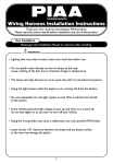
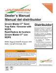
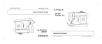
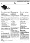
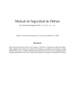
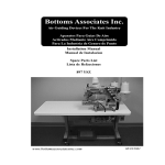
Bottoms Associates Inc. Air Guiding Devices For The Knit Industry Aparatos Para Guias De Aire Activados Mediante Aire Comprimido Para La Industria de Genero de Punto Installation Manual Manual de Instalacion Spare Parts List Lista de Refacciones 3897 PLF / 3897 PSF www.bottomsassociatesinc.com 10/12/1999 COPYRIGHT © 2000 By Bottoms Associates Inc. This manual is copyrighted. All rights reserved. This document may not, either in whole or in part be copied, reproduced, reduced or translated by means, either mechanical or electronic, without prior written consent from Bottoms Associates Inc. 282 Highway 341 North Barnesville, GA 30204 AIR HEMMER WARRANTY The air hemmer attachments and controls do not include a warranty of any type. This product is sold "as is" "where is." BOTTOMS ASSOCIATES INC. IS NOT RESPONSIBLE FOR ANY LOST PROFITS, LOST SAVINGS, OR OTHER INCIDENTAL OR CONSEQUENTIAL COSTS, EXPENSES, OR DAMAGES ARISING OUT OF THE USE OF, OR INABILITY TO USE, THIS PRODUCT. THIS INCLUDES DAMAGES TO PROPERTY AND, TO THE EXTENT PERMITTED BY LAW, DAMAGES FOR PERSONAL INJURY. THIS WARRANTY IS IN LIEU OF ALL OTHER WARRANTIES INCLUDING IMPLIED WARRANTIES OF MERCHANTABILITY AND FITNESS FOR A PARTICULAR PURPOSE. Some states do not allow limitation of implied warranties, or exclusion or limitation of incidental or consequential damages, so the above limitations may not apply to some purchasers. This warranty gives the purchaser some specific legal rights. The purchaser may have other rights which may vary from state to state. This warranty applies only to this product and is governed by the laws of the State of Georgia. Bottoms Associates Inc. reserves the right to revise and improve its products as it sees fit. This publication describes the state of this product at the time of its publication and may not reflect the product at all times in the future. It is unlawful to accomplish two needle bottom hemming using the device and method described in U.S. Patent #5,373,797 which are manufactured or supplied by companies other than Bottoms Associates Inc. It is against U.S. Federal Law to use this device or method to assemble garments intended for shipment into the United States P L F These devices are protected by one or more of the following patents: 5,373,797; 5,441,004 & 6,119,612. Other U.S. and Foreign patents pending © 2000 Bottoms Associates Inc. 2 REQUIRED COMPONENTS 1. STAND (EXISTING) At least 30" wide preferred. Adjust height for operator comfort. 2. TABLETOP (EXISTING) Flat top, 30" x 30" preferred. 3. MOTOR (EXISTING) Motor controller must have programmable features and start-stop sensors. 4. MACHINE (EXISTING) *Pegasus WT500 binding machine with a presser foot wide enough to cover desired hem width. 5. TREADLE FOOT CONTROL (EXISTING) Remote treadle control preferred. 6. FILTER REGULATOR (EXISTING) Normal operating pressure 40 psi. (0.28 Kgf/cm²) 7. 24VDC SOLENOID VALVE (EXISTING) Valve flow of at least .35 CV. 8. MOTOR BREAKER OR SWITCH (EXISTING) Position motor switch to allow operator to sit or stand. Fig.#1 * "Pegasus" is a Trademark of PegasusUSA 3 INSTALLATION 3897 PLF On *Pegasus WT500 Fig.#3 WT 500 Bed Plate Modification Fig.#2 Illustrated with #01 Hem Cover Plate Removed MODIFICATION OF MACHINE Remove left side of bed plate. Modify bed plate (see figure #3 above), Machine off 1.470 in./ 37.338mm. of the front part of the machine bed plate. Remove or modify the side door so that it does not interfere with the air guide machine adaptor #06 (see figure #4 page #5). Loosen mounting screws on the front door and adjust so that it is fully down. Cut off right side of presser foot so that distance between outside needle and right edge of foot is equal to the desired hem width. INSTALLATION OF 3897 PLF Remove machine adaptor and rod assembly from air guide by loosening Plastic Lock Handle #28 and remove rear pinch collar #30 (see figure #4 page #5). Secure machine adaptor to threaded holes located on lower left side of machine casting below machine bed cover with two screws #32. Make sure that block tightens flush with machine casting. Loosen the three flat head screws #21 and remove the hem cover plate assembly. Slide air guide onto rods until Exhaust Plate #10 strikes throat plate of machine. Adjust Exhaust Plate by loosening screws #33 and #23 and aligning right edge of exhaust plate 1/16" (1.6mm) to right of outside needle (see figure #2). Tighten screw #23. Adjust hem cap assembly so that Edge Guide #29 rests against the presser foot (make sure edge guide is square with folder). Snug screws #33. Loosen screws #20 and slide Entrance Plate #14 to the left to close any gap between the entrance plate and throat plate. Tighten screws. Reinstall the top plate assembly so that there is approximately a 1/ 16" (1.6mm) gap between it and the inside of the hem cap #12. Adjust Pinch Collars #30 so that inside collar stops air guide just before it jams into machine and outer collar so that air guide can be retracted to allow front door to be opened. Tighten Plastic Lock Handle before sewing on machine. AFTER MAKING ALL OF THE ABOVE ADJUSTMENTS, MAKE SURE THAT PARTS ARE SQUARE TO EACH OTHER BEFORE TIGHTENING DOWN. OPERATION OF 3897 PLF With needles in the down position, place sleeve on hem cover plate covering sensor. Solenoid valve should come on suppling air to hem cap. Sleeve will turn down all the way to exhaust plate. Delay for machine run should start, (.5 sec. to 1.0 sec). Operator should pull sleeve under top feed during the delay time, release sleeve, machine run after delay time. Supply air will remain on until sensor is uncovered. After sensor in uncovered stitch count should start for machine to stop at end of sleeve (01-40 stitches), machine should stop with the needles in the down position at end of sleeve. After sleeve has been placed in proper starting position the operator should reach for the next sleeve during machine run time. Machine will start automatically when sensor is covered. For emergency stop, the operator should heel back on pedal. 4 PROBLEM TROUBLE SHOOTING POSSIBLE CAUSE AIR NOT FLOWING FROM HEMMER Low or no pressure to solenoid valve. Regulator is off. Air line is pinched. AIR FLOWING ALL THE TIME Sensor not adjusted properly. HEM VARIES IN WIDTH guide Hem cover plate gap to hem cap not adjusted properly. Gap between edge HEM ROLLS UP Folder capacity too large. RAW EDGE VARIES FROM STITCH MARGIN Material not cut straight. and preser foot. RAW EDGE NOT CAUGHT AT START OF HEM SLEEVE TWISTING Operator not placing sleeve under feed at start. Loading sleeve at an angle. Fabric not cut straight. Top and bottom feeds not adjusted properly. Too much pressure on foot. DRAIN FILTER BOWL DAILY. MAINTENANCE CLEAN ALL LINES, FILTER REGULATOR, & FOLDER WITH HOT SOAPY WATER IF SYSTEM HAS FILLED WITH OIL, WATER . NO OIL SHOULD BE ALLOWED TO ENTER SYSTEM. CHANGE AIR FILTER AT LEAST EVERY 3 MONTHS. CHECK AND SECURE ALL AIR CONNECTIONS. CLEAR ALL STRINGS AND LINT FROM EXHAUST PLATE FOR BEST PERFORMANCE. WIPE LINT AND DUST FROM LENSES REGULARLY. REPLACE ANY DAMAGED PARTS AS NEEDED. CHECK GAUGE PRESSURE AT REGULAR INTERVALS TO INSURE MINIMUM AIR USAGE. AIR CONSUMPTION RATING 4.9 S.C.F.M. AT 40 P.S.I. NOTES COMPLETE INSTALLATION, ADJUSTMENT AND SEW OFF TAKES APPROXIMATELY 45 MINUTES. If a problem with this product cannot be solved, please contact Bottoms Associates Inc. Technical Support Department. Operation from 8:00 am. to 4:00 pm. Eastern Time Monday through Friday excluding holidays. Tele: (770) 358-1344, Fax:(770) 358-6038 5 Patent# 5,373,797 & 5,441,004 and other Patents Pending 6 Parts for 3897 PLF 01 3897-01 Hem Cover Plate 02 3897-02L Spacer Bar, Light 1 03 3897-03 Angle Mount Bracket 04 3897-04 Top Hem Guide 05 3897-05 Slide Bracket 06 3897P-01 Machine Adaptor 07 3897-07 Guide Rod 08 3897-08 Lock Rod 09 3897-09 Adjustment Block 10 3897-10L Exhaust Plate .060 Light 11 3897-11 Adjustment Plate 12 3897-12L Hem Cap .060 Light 13 3897-13 Clamp Bar 14 3897-14 Entrance Plate, W/Reflective Tape 15 3897-15L Edge Guide Bracket .060 Light 17 KJL07-34S Elbow, Mini 1/4 Tube X 1/8 Npt 18 91375A535 1/4-20 X 3/8" Set Screw C.P. 19 91253A106 4-40 X 1/4" Flat Head S.C.S. 20 91255A106 4-40 X 1/4" B.H.S.C.S. 21 91253A197 8-32 X 3/4" Flat Head S.C.S. 22 91251A540 1/4-20 X 3/4" Socket Cap Screw 23 91255A194 8-32 X 1/2" Button Head S.C.S. 25 91166A210 M-3 Flat Washer 26 91166A250 M-6 Flat Washer 27 91166A230 M-4 Flat Washer 28 KHA110 1/4-20 X .875 Plastic Handle 29 897-02B Edge Guide 30 6435K14 1/2"Idx1 1/8"Od Steel Pinch Collars 31 91375A437 10-32 X 3/16" Set Screw C.P. 32 91290A326 M6 X 1.0 X 20mm Socket Cap Screw 33 91253A194 8-32 X 1/2" Flat Head S.C.S. 34 90945A111 4-40 Washer (Nas 620-4) 1 1 1 1 1 1 1 1 1 1 1 1 1 1 1 2 6 6 3 2 1 4 2 2 1 1 2 6 2 2 2 Units avaliable in (L)ight (0.060), (S)tandard (0.100) Capacities. All units shipped with (L)ight capacity unless otherwise specified. Convert from .060 capacity to .100 capacity Specify Part# 3897-02S, 3897-10S, and 3897-12S Convert from .100 capacity to .060 capacity Specify Part# 3897-02L, 3897-10L, and 3897-12L Unidades disponibles en capacidades (L)delgado 1.5 mm, (S)estandar 2.54 mm. Todas las unidades son enviadas con (L)1.5 mm de capacidad a menos que sea especificado de otra forma. Para convertir de capacidad de 1.5mm a 2.54mm especifique parte #3897- 02S, 3897-10S y 3897-12S. Para convertir de capacidad de 2.54mm a 1.5mm especifique parte #3897- 02L, 3897-10L y 3897-12L. 7 Derecho de Propiedad Literaria (C) 2000 Por Bottoms Associates Inc. Este manual es de propiedad registrada. Derechos Reservados. Es prohibido copiar, reducir, o traducir mecanicamente o electronicamente este documento en parte o completo sin previo permiso escrito de Bottoms Associates Inc. 282 Highway 341 North Barnesville, GA 30204 GARANTIA DEL BASTILLADOR DE AIRE(TM) BOTTOMS ASSOCIATES INC. NO SERA RESPONSABLE POR CUALQUIER PERDIDA DE LUCRO, AHORROS, U OTROS DAÑ0S INCIDENTALES O DE CONSECUENCIA SURGIDOS POR USO O LA INABILIDAD DE USAR ESTE PRODUCTO. ESTO INCLUYE DAÑOS A PROPIEDAD Y, AL PUNTO PERMITIDO POR LA LEY, DAÑOS PERSONALES. ESTA GARANTIA PRECEDE TODA OTRA GARANTIA INCLUYENDO GARANTIAS IMPLICANDO MERCABILIDAD O ABILIDAD DE USAR PARA EJERCER UN PROPOSITO ESPECIFICO. Algunos estados no permiten limitacion de garantias implicadas o exclusiones o limitaciones de daños incidentales o de consecuencia, asi que es posible que las limitaciones sobredichas no apliquen a unos clientes. Esta garantia da al cliente algunos derechos legales especificos. El cliente puede tener otros derechos que varian de estado a estado. Esta garantia se aplica nada mas a este producto, y esta gobernado por las leyes del estado de Georgia. Bottoms Associates Inc. reserva el derecho de revisar y mejorar sus productos como lo considere conveniente. Este manual describe la condicion de este producto al tiempo de su publicacion y no puede reflejar el producto en el futuro. P L Patente# 5,373,797 Y 5,441,004 Y 6,119,612 y otros Patentes Pendientes F 8 COMPONENTES REQUERIDOS 1. PEDESTAL (YA EXISTE) Por lo menos 30" de ancho preferible. Ajuste la altura para la comodidad de la operaria. 2. TABLA DE MESA (YA EXISTE) Superfice plana, 30" x 30" preferible. 3. MOTOR (YA EXISTE) El controlador del motor debe de ser con facciones programables y un sensor de arranque y paro. 4. MAQUINA (YA EXISTE) *Pegasus WT500 maquina collaretera con un pie prensa-tela suficientemente ancho para cubrir el ancho de la costura deseada. 5. PEDAL CON VARILLA DE CONTROL DE VELOCIDAD (YA EXISTE) Control remoto (con cable) ergonomico preferible. 6. FILTRO-REGULADOR DE AIRE COMPRIMIDO (YA EXISTE) Presion normal de operacion de 0.28 Kgf/cm² (40 psi). 7. VALVULA SOLENOIDE DE 24VDC (YA EXISTE) Valvula con capacidad de flujo de aire de un minimo de .35 CV. 8. INTERRUPTOR DE VOLTIOS PRINCIPAL (YA EXISTE) Posicione el interruptor principal para permitir a la operaria que se siente o se pare. ver Figura #1 * "Pegasus" is a Trademark of PegasusUSA 9 INSTALACION DE 3897 PLF EN *Pegasus WT500 Fig.#3 WT 500 Bed Plate Modification ver Figura#2 Ilustrado con #01 Placa Cubierta removido MODIFICACION DE LA MAQUINA Remueva el lado izquierdo de la cubierta de la máquina. Modifique la cubierta de la máquina (vea figura N°3). Acorte 1.470 in/37.338mm de la frente de la cubierta de la máquina. Quite o modifique la puerta lateral de la máquina para que no interfiera con el bloque-adaptor de guía de aire N°06 (vea ilustración N°3, pagina N°5). Afloje los tornillos de montadura de la puerta delantera y ajústela completamente abajo. Corte el lado derecho del pie prensa-tela para que la distancia entre la aguja izquierda y la orilla derecha del pie sea igual al ancho de la bastilla. INSTALACION DEL 3897 PLF Remueva el bloque-adaptor y varilla de instalación de la guía de aire aflojando la Manivela Plástica N°28 (vea figura N°3 pagina N°5) y remueva el anillo sujetador de atrás N°30 (vea figura N°4, página N°5). Asegure el bloqueadaptor en los hoyos enroscados localizados en la parte baja izquierda de la fundición de la máquina de bajo de la cama de la máquina con dos tornillos N°32. Asegúrese que el bloque-adaptor esté asegurado nivelado a la fundición de la máquina. Afloje los tres tornillos de cabeza plana N°21 y remueva el montaje de la placa cubierta. Resbale la guía de aire en las varillas hasta que la Placa de Escape N°10 choque con la plancha de la máquina. Ajuste la Placa de Escape aflojando los tornillos N°33 y N°23 y alineando la orilla derecha de la Placa de Escape 1.6 mm (1/16") hacia la derecha de la aguja izquierda (vea figura N°2). Apriete el tornillo N°23. Ajuste el montaje de la tapa del bastillador para que la Guía de Orilla N°29 se apoye en el lado del pie prensa-tela (asegúrese de que la Guía de Orilla está cuadrada con el dobladillador.) Apriete los tornillos N°33. Afloje los tornillos N°20 y resbale la Placa de Entrada N°14 hacia la izquierda para cerrar cualquier abertura entre la placa de entrada y la plancha. Apriete los tornillos. Reinstale la placa cubierta para que allí haga una abertura de aproximadamente 1.6mm (1/16") entre ésta y el interior de la tapa del bastillador N°12. Ajuste los Anillos Sujetadores N°30 para que el anillo interior pare la guía de aire justamente antes de que éste se atasque dentro de la máquina y el anillo exterior para que la guía de aire sea retractable para permitir que la puerta delantera pueda abrirse. Apriete la Manivela antes de coser en la máquina. DESPUES DE HACER TODOS LOS AJUSTES ANTES MENCIONADOS, ASEGURESE DE QUE LAS PARTES ESTEN QUADRADAS UNAS A OTRAS ANTES DE SER APRETADAS. 10 OPERACIONA DE 3897 PLF Con las agujas en posición baja, coloque la Manga en la placa cubierta cubriendo el sensor. La válvula Solenoide debe de activar abasteciendo de aire a la tapa del bastillador. La orilla de la manga se doblará hacia abajo completamente hasta la placa de escape. Tarda el comienzo de coser la máquina (.5 sec. a 1.0 sec). La operadora debe de posicionar la manga bajo los dientes superiores durante el conteo de tiempo y soltar la manga cuando comienze la máquina. El abastecimiento de aire se mantendrá encendido hasta que el sensor sea destapado. Después que el sensor sea destapado el conteo de puntadas de la máquina deberá de empezar para que pare al final de la manga (01-40 puntadas), la máquina deberá de parar con las agujas en posición baja al final de la manga. Después de que la manga se haga puesto en la posición de arranque correcta la operadora deberá de alcanzar la próxima manga durante el tiempo de corrido de la máquina. La máquina empezará a coser automáticamente cuando el sensor esté cubierto. Para parado de emergencia, la operadora debe de accionar el pedal hacia atrás. 11 PROBLEMA INVESTIGACION DE FALLAS CAUSA POSIBLE NO HAY CORRIENTE DE AIRE DEL BASTILLADOR Presión bajo o cero presión hacia la válvula solenoide. Válvula reguladora estáapagada. Linea de aire está apretada. AIRE FLUENTE TODO EL TIEMPO El sensor no estáajustado apropiadamente. VARIEDAD EN EL ANCHO DE LA COSTURA Espacio entre la placa cubierta y tapa del bastillador no ha sido adecuadamente ajustado. Espacio entre la guía de orilla y pie prensa-tela. COSTURA RUEDA HACIA ARRIBA La capacidad del bastillador es muy grande. LA ORILLA DE LA TELA VAREA ABAJO DE LA PUNTADA El material no está cortado derecho. LA ORILLA DE LA TELA NO ESTA ABAJO DE LA PUNTADA AL PRINCIPIO La operadora no está montando la manga abajo de los dientes al empezar. Montando la manga en un angulo. El material no está cortado derecho. TORCEDURA DE MANGA Dientes superiores e inferiores no han sido propiamente ajustados. Demasiada presión en el pie. MANTENIMIENTO DRENE EL TAZON DEL FILTRO DIARIAMENTE. LIMPIE TODAS LAS LINEAS, REGULADOR DE FILTRO, Y DOBLADILLADOR CON AGUA Y JABON CALIENTE SI EL SISTEMA SE HA LLENADO CON ACIETE O AGUA. CERO ACIETE ES PERMITIDO QUE ENTRE AL SISTEMA. CAMBIE EL FILTRO DE AIRE POR LO MENOS CADA 3 MESES. REVISE Y APRIETE TODAS LAS CONEXIONES DE AIRE. LIMPIE TODOS LOS HILOS Y PELUSA DE LA PLACA DE ESCAPE PARA UN MEJOR FUNCIONAMIENTO. REEMPLACE CUALQUIER PARTE DAÑADA A MEDIDA QUE SE VAYA NECESITANDO. REVISE EL INDICADOR DE PRESIÓN EN INTERVALOS REGULARES PARA ASEGURAR EL USO MÍNIMO DE AIRE. PORCENTAJE DEL CONSUMO DE AIRE 4.9 S.C.F.M. A 40 P.S.I. NOTAS LA INSTALACIÓN Y AJUSTMIENTO DE COSTURA TOMA APROXIMADAMENTE 45 MINUTOS. Si algun problema con este producto no puede ser resuelto, por favor comuniquese con Bottoms Associates Inc. Departamento de Soporte Tecnico. Operan de 8:00 a.m. a 4:00 p.m. Hora del Este de lunes a viernes excluyendo dias festivos. Tel:(770) 358-1344, Fax:(770) 358-6038 12 13 14 15