1
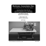
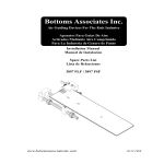
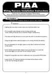
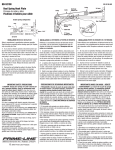
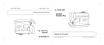
Bottoms Associates Inc. Air Guiding Devices For The Knit Industry Aparatos Para Guias De Aire Activados Mediante Aire Comprimido Para La Industria de Genero de Punto Installation Manual Manual de Instalacion Spare Parts List Lista de Refacciones 897 PSZ www.bottomsassociatesinc.com 08/28/2001 COPYRIGHT © 2000 By Bottoms Associates Inc. This manual is copyrighted. All rights reserved. This document may not, either in whole or in part be copied, reproduced, reduced or translated by means, either mechanical or electronic, without prior written consent from Bottoms Associates Inc. 282 Highway 341 North Barnesville, GA 30204 AIR HEMMER WARRANTY The air hemmer attachments and controls do not include a warranty of any type. This product is sold "as is" "where is." BOTTOMS ASSOCIATES INC. IS NOT RESPONSIBLE FOR ANY LOST PROFITS, LOST SAVINGS, OR OTHER INCIDENTAL OR CONSEQUENTIAL COSTS, EXPENSES, OR DAMAGES ARISING OUT OF THE USE OF, OR INABILITY TO USE, THIS PRODUCT. THIS INCLUDES DAMAGES TO PROPERTY AND, TO THE EXTENT PERMITTED BY LAW, DAMAGES FOR PERSONAL INJURY. THIS WARRANTY IS IN LIEU OF ALL OTHER WARRANTIES INCLUDING IMPLIED WARRANTIES OF MERCHANTABILITY AND FITNESS FOR A PARTICULAR PURPOSE. Some states do not allow limitation of implied warranties, or exclusion or limitation of incidental or consequential damages, so the above limitations may not apply to some purchasers. This warranty gives the purchaser some specific legal rights. The purchaser may have other rights which may vary from state to state. This warranty applies only to this product and is governed by the laws of the State of Georgia. Bottoms Associates Inc. reserves the right to revise and improve its products as it sees fit. This publication describes the state of this product at the time of its publication and may not reflect the product at all times in the future. It is unlawful to accomplish two needle bottom hemming using the device and method described in U.S. Patent #5,373,797 which are manufactured or supplied by companies other than Bottoms Associates Inc. It is against U.S. Federal Law to use this device or method to assemble garments intended for shipment into the United States 897 P S Z These devices are protected by one or more of the following patents: 5,373,797 & 5,441,004 & 6,119,612. Other U.S. and Foreign patents pending © 2000 Bottoms Associates Inc. Type of Unit Special Identifier Options Z=Miniture Semi Automatic Capacity L= Light .060-.100 S=Standard .100-.135 Machine Class P= Pegasus* 664 P= Pegasus* WT664 W= Pegasus* WT200 (when crossing seams, top feed required) 2 REQUIRED COMPONENTS 1. STAND (EXISTING) At least 36" wide preferred. Adjust height for operator comfort. 2. TABLETOP (EXISTING) Flat top, 24" x 48" preferred. 3. MOTOR (EXISTING) Motor controller must have programmable features. 4. MACHINE (EXISTING) *Pegasus WT664 with a presser foot wide enough to cover desired hem width. 5. 897 PSZ AIR HEMMER Includes air valves and air lines. 6. PEDAL FOOT CONTROL (EXISTING) Adjust for operator comfort. 7. FILTER REGULATOR (EXISTING NOT SHOWN) 8. FILTER REGULATOR, SENSOR AND SOLENOID VALVES 897 PSZ control includes fittings for installation to existing filter regulator, standard or metric. 5 4 2 8 3 6 1 * "Pegasus" is a Trademark of Pegasus, Inc. 3 TYPICAL INSTALLATION 897 PSZ AIR HEMMER TO *PEGASUS WT664 (1) INSTALLATION (1) Install the 897 PSZ to the holes located on front left side of machine front door. (2) Align #10 Exhaust plate 1/16" (1.6mm.) to the right of the outside needle. Fasten using two screws #12 and #25 flat washers supplied. 25 12 (2) Edge Adjustment 1/16" (1.6mm) 05 07 10 * "Pegasus" is a Trademark of Pegasus, Inc. 4 (3) To adjust width of hem, loosen screw #13 and slide #05 Hem Cap to desired width measuring from #10 Exhaust Plate edge to inside Hem Cap edge and then subtracting 1/8" (3.2mm). Right side of presser foot may need to be cut off or added to depending on hem width desired) This measurement may need to be fine tuned at sew off. (4) Using a 9/32" opened end wrench loosen nut #19 them rotate cylinder rod so #07 Cover Plate aligns 1/16" (1.6mm) to the left of outside needle. Hemmer maximum capacity is determined by the thickness of #10 Exhaust Plate. Should the distance between the #07 Cover Plate and #05 Hem Cap require adjusting, loosen the screw on clamp #35 and adjust to the right or left to obtain the same distance or opening as the #10 Exhaust Plate thickness and retighten screw. (3) Adjustment of Hem Width - 1/8" 05 10 13 07 (4) Adjusting the Capacity /Opening of the Cover Plate 35 19 5 Drill 3/4" (19 mm) diameter hole through table top using the measurement listed below. 1" (25 mm) 4 1/2" (144 mm) 7" (177 mm) Attach regulator, valve, and sensor mounting bracket as shown using #42 screws and #40 flat washers supplied. From center of hole to center of gauge 4 1/2" (144 mm). From front of table top to front of mounting bracket 7" (177mm). 6 Air Line and Fiber Cable Connections Air Guide D A B E C Receive Transmit B A E D C Air Regulator , Solenoid Valve, Air Manifold and Fiber Optic Sensor 7 Route the air lines and fiber optic cables coming from the air guide through the table top, connecting to the valve manifold and sensor as shown. When depressing the manual override orange button on the air valve, the folder should close and the air should be exhausted from hemmer. When depressing the green override button on the air valve, the folder should open and the air should go off. The light emitted from the sensor must follow the path of the arrows. If the fibers require cutting use only the cutter supplied with the unit. (See the sensor manufacturers specification for cutting fibers). Press fibers into sensor firmly and lock handle. Make sure there is enough slack to allow for opening and closing the machine door as not to pull fiber cables or air line taut. Connect the wiring harness from the control to the motor. Program the motor controller. The 897 PSZ is now ready for testing and sew off. NOTE: We recommend that the air lines and fiber optic cables be cut off as short as possible to eliminate any excess or distance from control to folder. SENSOR SETTING This is only required if the unit will not operate properly after setup is complete. The sensor has been preset in our facility when assembled. Only use a plastic screw driver like the one supplied to adjust the sensor. (1) Rotate adjustment screw on front of sensor counter clockwise for minimum sensitivity setting (the first mark on the bottom left of indicator). (2) Rotate the adjustment screw on the front of the sensor clockwise, usually the third mark on the indicator. The red LED should come on with no fabric present. The 897 PSZ is now set for automatic opening. Also see sensor manufacturers specification sheet enclosed with 897 PSZ Air Hemmer for other settings. (1) Turn counter clockwise until the screw clicks or the green LED is the only one illuminated. (2) Turn clockwise until the red LED and green LED is illuminated. 8 TESTING AND SEW OFF Perform the following steps to check for proper operation. (1) Heel back on treadle. Folder should close and air should exhaust from hemmer. PLACE LOOP OF FABRIC UNDER PRESSER FOOT THROUGH AIR HEMMER. Sensor red LED should turn off. (2) Toe down on treadle, air should exhaust from hemmer, machine should begin to sew. (3) Sew around loop to starting point, sensor red LED should turn on, air hemmer should open, machine should start a stitch count, suggested over sew distance 1" (25 mm) (also see machine manufacturer and specific motor controller manual for specifications). After stitch count, machine should stop, position, trim thread, and foot should lift. If unit does not operate as described above, take a pencil and depress manual override buttons located on the solenoid valve. If the unit works when depressing these buttons check motor controller for proper settings and wiring cable to insure proper connection to motor controller and 897 PSZ Air Hemmer. 9 TROUBLE SHOOTING PROBLEM Possible Cause MAINTENANCE DRAIN FILTER BOWL DAILY. AIR NOT FLOWING FROM HEMMER Low or no pressure to unit. Regulator valve is off. Air line is pinched. No signal to valve from motor controller. AIR FLOWING ALL THE TIME Treadle binding or valves sticking. FOLDER OPENING & CLOSING TOO SLOW OR TOO FAST Hem width adjustment screws too tight. Incorrect air pressure. FOLDER CLOSES AFTER OPENING Operator heeling back on treadle. HEM VARIES IN WIDTH Clear cover plate gap not adjusted. Foot not covering hem. HEM ROLLS UP Operator is stretching fabric. Material not cut straight. Folder capacity too large. RAW EDGE VARIES FROM STITCH MARGIN Operator guiding or holding back on fabric. Material not cut straight. RAW EDGE NOT CAUGHT AT SEAM Folder has too small capacity. Material not sewn together even at seam. RAW EDGE NOT CAUGHT AT START OF HEM Operator not pulling garment around far enough or is pulling it at an angle. Fabric not cut straight. FINISHING STITCHES NOT IN LINE WITH STARTING STITCHES Stitch over finger not adjusted properly. Exhaust plate edge too far to the right or left of the outside needle. Operator is starting off at an angle. Material is not cut straight. FOLDER VIBRATING ON MACHINE BED Readjust vertical position of folder bracket. CLEAN ALL LINES, FILTER REGULATOR, & FOLDER WITH HOT SOAPY WATER IF SYSTEM HAS FILLED WITH OIL, WATER . NO OIL SHOULD BE ALLOWED TO ENTER SYSTEM. CHANGE AIR FILTER AT LEAST EVERY 3 MONTHS. CHECK AND SECURE ALL AIR CONNECTIONS. CLEAR ALL STRINGS AND LINT FROM EXHAUST PLATE FOR BEST PERFORMANCE. WIPE LINT AND DUST FROM LENSES REGULARLY. REPLACE ANY DAMAGED PARTS. CHECK GAUGE PRESSURE AT REGULAR INTERVALS TO INSURE MINIMUM AIR USAGE. AIR CONSUMPTION RATING 3.2 S.C.F.M. AT 40 P.S.I. NOTES COMPLETE INSTALLATION, ADJUSTMENT AND SEW OFF TAKES APPROXIMATELY 30 MINUTES. If a problem with this product cannot be solved, please contact Bottoms Associates Inc. Technical Support Department. Operation from 8:00 am. to 4:00 pm. Eastern Time Monday through Friday excluding holidays. Tele: (770) 358-1344, Fax:(770) 358-6038 10 897 PSZ Air Hemmer Wiring Diagram 11 12 Parts for 897 PSZ 01 897Z-01 02 897Z-02 03 897Z-03 04 897Z-04 05 897Z-05S 06 897Z-06 07 897Z-07 08 897Z-08L 09 897Z-09 10 897Z-10L 11 897YZ-01 12 91239A148 13 91290A119 14 91239A111 15 91239A117 16 91294A128 17 91390A117 18 91294A125 19 91828A231 20 FXLE1 21 FT-P80 22 897Z-W 23 91290A111 24 91166A210 25 91166A230 26 M-5ALU-4 27 M-5AU-6 28 M-5ALU-6 29 M-5UT 30 M-5AU-4 31 FX-M1J 32 4568K113 33 NAW2000-N01G-4CR-X34 34 NAW2000-B1 35 SH12-1818.157.F-1 36 RSR5WMUU+50LM 37 SX3440-5LOZ-01 38 M-5B 39 CD-Z015 40 CJ2D10-ULA980139 41 KQ2L06-U01 42 90190A247 43 91166A250 44 897Z-13 45 AN103-01 46 CP012-1R5-ND 47 1J-127-01 48 TU0604B 49 1B-156-01 5/32 50 897PZ-02 51 91253A003 Seam Spring Plate Edge Guide Fiber Bracket Cylinder Mount Hem Cap .100 Standard Sensor Reflector Cover Plate Cylinder To Cover Adaptor Carriage Stop Exhaust Plate Machine Adaptor M4 X 12mm Button Head Cap Screw M3 X 14mm Socket Head Cap Screw M3 X 6mm Button Head Cap Screw M3 X 12mm Button Head Cap Screw M3 X 8mm Flat Head Cap Screw M5 X 5mm Socket Head Set Screw M3 X 5mm Flat Head S.C.S. M4 Hex Nut Lens High Flex Fiber Set Cable W/ Connectors 897z not shown M3 X 6 Socket Head Cap Screw M-3 Flat Washer M-4 Flat Washer Barb Elbow 4mm Tube page 11 Barb Fitting 6 Mm Tube Barb Elbow 6mm Tube page 11 M5 Tee page 11 Barb Fitting 4mm Tube page 11 Amplifier page 11 2" Brass Pipe Nipple page 11 US 55/Filter Regulator W/O Bracket page 11 Mounting Bracket For Naw2000 Regulator page 11 4mm Hub Clamp W/ M3 Screw Ball Bearing Slide Sx Valve, 3 Psn, 24 Vdc, 1/8 Pt page 11 Bushing, 1/8 Pt X M5 page 11 Pin/Ring Cylinder Elbow, Unifit 6 Mm Tube page 11 10 X 1" Self-Tapping P.H.P. page 11 M-6 Flat Washer page 11 Foam Tape 3/4 X 1.8 page 11 Silencer page 11 Heat Shrinkable Tubing 1/2 X 1-1/2 1/2" Mesh Sleeving/Foot not shown 6mm Tubing not shown Tubing 5/32" Od. Polyurethane not shown Machine Adaptor 10-32 X 1/2" Flat Head S.C.S. 13 1 1 1 1 1 1 1 1 1 1 1 2 1 4 6 3 1 2 2 1 1 1 3 2 2 3 1 1 1 1 1 1 1 1 1 1 1 2 1 1 2 2 2 1 1 1 1 6 6 1 2 Derecho de Propiedad Literaria (C) 2000 Por Bottoms Associates Inc. Este manual es de propiedad registrada. Derechos Reservados. Es prohibido copiar, reducir, o traducir mecanicamente o electronicamente este documento en parte o completo sin previo permiso escrito de Bottoms Associates Inc. 282 Highway 341 North Barnesville, GA 30204 GARANTIA DEL BASTILLADOR DE AIRE(TM) Los dispositivos dobladilladores neumaticos y sus controles no incluyen garantia de ninguna clase. Este producto se vende tal como esta sin dar lugar a reclamaciones por donde quiera. BOTTOMS ASSOCIATES INC. NO SERA RESPONSABLE POR CUALQUIER PERDIDA DE LUCRO, AHORROS, U OTROS DAÑ0S INCIDENTALES O DE CONSECUENCIA SURGIDOS POR USO O LA INABILIDAD DE USAR ESTE PRODUCTO. ESTO INCLUYE DAÑOS A PROPIEDAD Y, AL PUNTO PERMITIDO POR LA LEY, DAÑOS PERSONALES. ESTA GARANTIA PRECEDE TODA OTRA GARANTIA INCLUYENDO GARANTIAS IMPLICANDO MERCABILIDAD O ABILIDAD DE USAR PARA EJERCER UN PROPOSITO ESPECIFICO. Algunos estados no permiten limitacion de garantias implicadas o exclusiones o limitaciones de daños incidentales o de consecuencia, asi que es posible que las limitaciones sobredichas no apliquen aunos clientes. Esta garantia da al cliente algunos derechos legales especificos. El cliente puede tener otros derechos que varian de estado a estado. Esta garantia se aplica nada mas a este producto, y esta gobernado por las leyes del estado de Georgia. Bottoms Associates Inc. reserva el derecho de revisar y mejorar sus productos como lo considere conveniente. Este manual describe la condicion de este producto al tiempo de su publicacion y no puede reflejar el producto en el futuro. 897 P L Z Patente# 5,373,797 Y 5,441,004 Y 6,119,612 y otros Patentes Pendientes Tipo de Unidad Indentificador Opciones Z=Miniatura Semi Automatico Identificador de Maquina P= Pegasus* 664 P= Pegasus* WT664 W= Pegasus* WT200 (cuando cosiendo por la costura, dientes superiores son requeridos) 14 Tamano de Capacidad L= Delgado 1.5 -2.5mm (.060 - .100) S=Estandar 2.5mm-3.4mm (.100 - .135) COMPONENTES REQUERIDOS 1. PEDESTAL (YA EXISTE) Por lo menos 36" de ancho preferible. Ajuste la altura para la comodidad de la operaria. 2. TABLA DE MESA (YA EXISTE) Superfice plana, 24" x 48" preferible. 3. MOTOR (YA EXISTE) El controlador del motor debe de ser con facciones programables. 4. MAQUINA (YA EXISTE) *Pegasus WT664 con un pie prensa-tela suficientemente ancho para cubrir el ancho de la costura deseada. 5. BASTILLADOR DE AIRE(TM) 897 PSZ Incluye valvulas de aire y manguerilla de aire. 6. CONTROL DE VELOCIDAD AL PEDAL Ajuste para la comodidad de la operaria. 7. FILTRO-REGULADOR DE AIRE COMPRIMIDO (YA EXISTE) 8. FILTOR-REGULADOR, SENSOR AND SOLENOID VALVES 897 PSZ incluye conexiones para conectar con el filtro-regulador que ya existe, sea tamaño estandar o metrico. 5 4 2 8 6 3 1 * "Pegasus" es una Marca de Fabrica de Pegasus, Inc. 15 INSTALACION TIPICA DEL BASTILLADOR DE AIRE 897 PSZ A *PEGASUS WT664 (1) INSTALACION (1) Instala el 897 PSZ a los agujeros localizado en frente lado izquierdo de la puerta delantera de la máquina. (2) Alinea la Placa de Escape N°10 1.6mm.(1/16") a la derecha de la aguja izquierda. Ate usando los dos tornillos N°12 y arandelas llanas N°25 suministrados. 25 12 (2) Ajuste del Borde 1.6mm (1/16") 05 07 * "Pegasus" es una Marca de Fabrica de Pegasus, Inc. 16 10 (3) Ajusta de Anchura de la Bastilla -3.2 mm (1/8") (3) Para ajustar la anchura de la bastilla, suelte tornillo N°13 y resbale Tapa del la Bastilla N°05 a anchura deseada midiendo de la orilla del Placa del Escape N°10 a la orilla de la Tapa de Bastilla interiro y entonces substraiga 3.2mm (1/8"). Puede ser necesario cortar o aumentar la orilla derecha de la prensa-tela según la anchura de la bastilla deseada. Esta medida necesitaría ajustarse a la comprobación de coser final. (4) Usando una llave abierta de 9/32", suelta tuerca N°19, rueda vara cillindro para que Placa de la Tapa N°07 se alinee 1.6mm (1/16") a la izquierda de aguja izquierda. La capacidad máxima del Bastillador es determinado por el espesor de la Place de Escape N°10. Si la distancia entre la Placa de la Tapa N°07 y la Tapa de la Bastilla N°05 requere ajusta, suelte el tornillo de abrazadera N°35 y ajusta a la derecha o la izquierda para obtener la misma distancia o abertura tal como el espesor de la Placa del Escape N°10 y apriete el tornillo de nuevo. 05 10 13 07 (4) Para Ajustar la Capacidad/La Abertura de la Tapa Placa 35 19 17 Taladre 19mm diámetro por la mesa usando la medida listado abajo. (25 mm) (144 mm) (177 mm) Ate regulador, válvula, anaquel de la montura del sensor como mostrado usando tornillas N°42 y arandelas llanas N°40 sumistraron. Desde el centro del agujero hasta el centro de medida es 144mm. Desde el frente del superficie la mesa hasta el fronte de anaquel de la montura es 177mm. Dirija las líneas del aire por el agujero y conecta al unidad de control. 18 Línea del aire y Conexiones del Cable de la Fibra Guía del aire D A B E C Reciba Transmita B A E D C Regulador del aire, Válvula del solenoide, tubo de unión múltiple del Aire y Sensor Fibra Optico 19 Dirija las líneas del aire y los cables de la fibra venida de la guía del aire por la superficie de la mesa. Conecte al tubo de unión múltiple de la válvula y sensor como mostrado. La luz emitido del sensor debe sequir el camino de las saetas. Si las fibras requireren cortarse, use sólo el cuchillo suministrado con la unidad. (Vea las especificaciones de la fabricante del sensor con respecto a cortar fibras.) Apriete las fibras hacia adentro del sensor firmemente y cierra asa. Asegúrese que basta flojera para permitir abrir y cerrar la puerta de la máquina puesto que no tirar tenso los cables de la fibra o la línea del aire. Conecte el conector mollex de 6 alfileres al cable de motor. Programe la unidad de control de motor. El 897 PSZ ya está listo para comprobar y coser. AJUSTO del SENSOR Esto sólo es requerido si la unidad no funciona apropiadamente. Este ajusto ha sido ejecutada en nuestra fábrica cuando se ha ensamblado. Use sólo un atornillador plástico como el suministrado para ajustar el sensor. (1) Ruede el tornillo del ajuste en frente de sensor contrario al sentido de las saetas del reloj como ajusto de la sensibilildad mínima (la primera marca del butón iz quierdo del indicador). (2) Ruede el tornillo del ajuste en el frente del sensor en el sentido de las saetas del reloj, usual mente la tercera marca en el indicado. El LED rojo debe encenderse sin tela presente. El 897 PSZ ya está fijo para abrir automáticamente. También vea hoja de la especificación de los fabricantes del sensor incluída con 897 PSZ Bastillador de Aire para otro ajustes. (1) Vuelva contador en el sentido de las saetas del reloj hasta que el tornillo suene con golpecito seco o el verde LED está la única encendida. (2) Vuelve en el sentido de las saetas del reloj hasta que LED roja y LED verde estén encendidas. 20 PRUEBA Y AJUSTES FINALES DE LA MAQUINA Lleve a cabo lospasos siguientes para revisar la debida operación. (1) Pisar hacia atrás pedal de pie. El doblillador debe de cerrar y aire debe escapar del bastillador. POSICIONE PRENDA DE TELA DEBAJO DE PRENSA-TELA POR BASTILLADOR del AIRE. Sensor LED roja debe apagarse. (2) Activar el pedal de pie. Aire debe escapar del bastillador y la máquina debe de empezar a coser. (3) Cosa alrededor de la prenda hacia el punto de partida. Sensor LED roja debeapagarse; la máquina debe empezar un conteo del puntaje. Se sugiere una distancia de sobre coser de 25.4mm (1" ). (También vea manual del fabricante de la máquina ymanual del unidad de control específico de motor para especificaciones.) Después de conteo del puntaje, la máquina debe pararse, posicionarse, cortar el hilo, y prensa-tele debe levantarse. Si la unidad no funciona como se ha descrito precedente, tome un lápiz y deprima los botones manuales de anular localizado en la válvula del solenoide. Si la unidad funciona cuando deprime estos botones, revise la unidad de control de motor para los ajustes propios y revise el cable de alambre para asegurar una conexión apropiada para la unidad de control del motor y el BASTILLADOR DE AIRE 897 PSZ. 21 MANTENIMIENTO ` DRENE EL TAZON DEL FILTRO DIARIAMENTE. LIMPIE TODAS LAS LINEAS, REGULADOR DE FILTRO, Y DOBLADILLADOR CON AGUA Y JABON CALIENTE SI EL SISTEMA SE HA LLENADO CON ACIETE O AGUA. CERO ACIETE ES PERMITIDO QUE ENTRE AL SISTEMA. CAMBIE EL FILTRO DE AIRE POR LO MENOS CADA 3 MESES. REVISE Y APRIETE TODAS LAS CONEXIONES DE AIRE. LIMPIE TODOS LOS HILOS Y PELUSA DE LA PLACA DE ESCAPE PARA UN MEJOR FUNCIONAMIENTO. LIMPIE LA PELUSA Y POLVO DE LOS LENTES REGULARMENTE. REEMPLACE CUALQUIER PARTE DAÑADA A MEDIDA QUE SE VAYA NECESITANDO. REVISE EL INDICADOR DE PRESION EN INTERVALOS REGULARES PARA ASEGURAR EL USO MINIMO DE AIRE. PORCENTAJE DEL CONSUMO DE AIRE 3.2 S.C.F.M. A 40 P.S.I. NOTAS LA INSTALACION Y AJUSTMIENTO DE COSTURA TOMA APROXIMADAMENTE 30 MINUTOS. BASTILLADOR DE AIRE 897 PSZ DIAGRAMA DE ALAMBRE INVESTIGACIÓN DE FALLAS PROBLEMA Causa Posible NO HAY CORRIENTE DE AIRE DEL BASTILLADOR Presión bajo o cero presión hacia la unidad. Válvula reguladora está apagada. Linea de aire está apretada. No hay señal del motor controlador hacia la válvula. AIRE CORRIENTE TODO EL TIEMPO Pedal de pie apretado o válvulas pegadas. SE ABRE O SE CIERRE DOBLADILLADOR MUY DESPACIOSO O MUY RAPIDO Los tornillos en el ajuste de la anchura están muy apretados. Presión de aire incorrecta. DOBLADILLADOR SE CIERRA DESPUES DE ABRIRSE Operaria taconea el pedal de pie. VARIEDAD EN EL ANCHO DE LA COSTURA La posicion de la Placa Cubierta no está ajustada. El pie no cubre la costura. COSTURA RUEDA HACIA ARRIBA La operaria está estirando la tela. El material no está cortado derecho. La capacidad del bastillador es muy grande. LA ORILLA DE LA TELA VAREA ABAJO DE LA PUNTADA La operaria guía o estádeteniendo la tela. El material no está cortado derecho. LA ORILLA DE LA TELA NO ESTÁ ABAJO DE LA PUNTADA La capacidad del dobladillador es muy pequeña. Material no ha sido cosido derecho en las costuras laterales. LA ORILLA DE LA TELA NO ABAJO DE LA AGUJA IZQUIERDA AL PRINCIPIO DE LA COSTURA. La operaria no está halando suficientemente la prenda alrededor o está halando en un angulo. El material no está cortado derecho. PUNTADAS FINALES NO ESTAN EN LINEA CON LAS DEL PRINCIPIO El Guía Dedal Superior no ha sido ajustado correctamente. La orilla de la Placa De Escape está mucho a la derecha o izquierda de la aguja izquierda.La operaria empieza en un angulo. El material no está cortado derecho. EL DOBLADILLADOR VIBRA EN LA CAMA DE LA MAQUINA Reajuste la posicion vertical del soporte del dobladillador. Si algun problema con este producto no puede ser resuelto, por favor comuníquese con Bottoms Associates Inc. Departamento de Soporte Tecnico. Operan de 8:00 a.m. a 4:00 p.m. Hora del Este de lunes a viernes excluyendo días festivos. Tel:(770) 358-1344, Fax:(770) 3586038 De Dobladillador 22 23