1
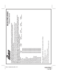
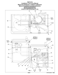
Model PA-120C
Installation Manual
Programmable Features
Select By Operating Transmitter
Siren Indications
1) Arming Method
2) Ignition Control Lock/Unlock
3) Passive Or Active Door Locks
4) Single Or Double Pulse U/L
5) Door Lock/Unlock Pulse Duration
6) Siren Chirps On/Off
7) Passive Rearm From Active State
8) Anti Hi-Jack Feature
9) Park Lights
Press Lock Button
1 Chirp
Passive Arm
Off
Active
Single Pulse
1 Second
On
On
Non Operational
Normal
Press Unlock Button
2 Chirps
Active Arm
On
Passive
Double Pulse
3 Seconds
Off
Off
Operational
15 Sec w/Lock
Factory Default
Passive Arm
Off
Active
Single
1 Second
On
On
Non Operational
Normal
To Program The Following Selectable Features:
1. Enter the vehicle, and turn the ignition key to the on position.
2. Press and release the valet/override/program push button switch 3 times.
Siren Chirps Once & Led Flash Once
3. Within 3 seconds, turn the ignition off thenn on, you will hear short chirp followed by long chirp.
4. Press and release the valet pushbutton switch one time to access feature #1. Use transmitter buttons to
change, or press the valet pushbutton switch to advance to the next feature. Turn the ignition switch off, or allow 60 seconds of
inactivity to exit the feature program mode.
NOTE: While in the program mode, if the ignition switch is turned off, or if 60 seconds of inactivity expire the program mode will
terminate, indicated by one short and one long chirp of the siren.
INSTALLATION OF THE MAIN COMPONENTS
Control Module : (P/N 1365274)
Select a mounting location inside the passenger compartment (up behind the dash), and secure using the two screws provided. The
control module can also be secured in place using cable ties. Keep in mind that the module has the on-board Shock Sensor and should
be mounted to a fairly rigid location to insure proper operation.
Do not mount the control module in the engine compartment, as it is not waterproof. You should also avoid mounting the unit directly
onto factory installed electronic components. These components may cause RF interference, which can result in poor transmitter
range or intermittent operation.
Hood or Trunk Pin Switch: (P/N 1363699)
A pin switch, not included, is intended for use in protecting the hood or trunk (or hatchback) of the vehicle. The switch must always
be mounted to a grounded, metal surface of the vehicle. It is important to select a location where water cannot flow or collect, and to
avoid all drip gutters on hood and trunk fender walls. Choose locations that are protected by rubber gaskets when the hood or trunk
lid is closed.
The pin switch can be mounted to a bracket provided, or direct mounting. Keep in mind that when properly mounted, the plunger of the
pin switch should depress at least ¼ “ when the hood or trunk lid is closed.
Dash Mounted LED: (P/N 1031118)
A small red LED is included that will serve as a visual indicator of the alarm status. It should be installed in the dash, located where it
can be easily seen from outside the vehicle, yet not be distracting to the driver.
Once a location has been selected, check behind the panel for wire routing access, and to confirm the drill will not damage any existing
components as it passes through the panel.
Drill a ¼“ diameter hole, and pass the red and blue wires from the LED through the hole, from the front of the panel. Firmly press the
body of the LED into the hole until fully seated.
Page 1
Rev a: 1/2013 Add Horn Reference
128-9112a
1 of 12
Valet/Programming/Hi-Jack Override Switch: (P/N 1541090)
Select a covert location for this switch within reach of the driver of the vehicle. This switch can be mounted below a dash panel,
under the driver's seat. This switch must be within reach of the operator of the vehicle. The locations mentioned are hidden from
view and will be known only to the vehicle operator yet they allow activation of the switch when necessary.
WIRING THE SYSTEM
5 Pin Main Connector: (P/N 1032707)
White / Red Wire: Parking Light Input.
This wire supplies the source for the On-Board Parking Light Relay. If the vehicle’s circuit switches + 12 Volts to the parking light
circuit, no change required. If the vehicle switches grount to the parking light circuit, cut this wire from the module side of the fuse,
and connect to chassis ground.
White Wire: Parking Light Output (10 Amp Max)
This wire is provided to flash the vehicle’s parking lights. Connect the white wire to the positive side of one of the vehicle’s parking
lights. For more security add a 10 Amp fuse to this wire to prevent possible shorting of the parking light and circumvention of the alarm
system.
Black Wire: Chassis Ground
Connect this wire to a solid, metal part of the vehicle’s chassis. Do not confuse this wire with the thin black antenna wire that exits
the control module independently.
Brown Wire: Positive Output to Siren or Negative Output To Horn Relay
Route this wire through a rubber grommet in the firewall, and to the siren location.
Connect the brown wire to the positive wire of the siren. Secure the black ground wire of the siren to chassis ground.
If connecting to the vehicles horn relay, change the jumper on the module to the correct position as shown in the diagram and then
connect the brown wire to the low current negative pulse side of the horn relay. This wire’s output is constant (+) when the jumper
is selected for siren, and pulsed (-) when selected for horn.
Red Wire: +12 VDC Circuit Supply 15 Amp Max
This 15 Amp fused wire supplies +12 volts to the module circuit and the parking light flash relay. Connect this wire to a constant 12
volt source capable of at least 15 Amps.
6 Pin Input/Output Harness (P/N 1032708)
Purple Wire: + DOOR TRIGGER
If the vehicle’s door courtesy light switches have a + 12 volt output when the door is opened (most Fords and some Imports), you
must connect this wire to the positive output from one of the door switches. In most cases, the purple wire will only needs to be
connected to one door switch, no matter how many doors the vehicle has.
WARNING: Do not use the purple wire if the vehicle has ground output type door switches. (See Brown Wire).
Note for vehicles with interior delay lighting see programming under title "Completing The Installation".
Blue Wire: ( - ) Instant Trigger Zone
This is an instant on ground trigger wire. It must be connected to the previously installed hood and trunk pin switches.
Green Wire: - DOOR TRIGGER
If the vehicle’s courtesy light switches have a ( - ) ground output when the door is opened (GM and most Imports), you must connect
this wire to the negative output from one of the door switches.
WARNING: Do not use the brown wire if the vehicle has + 12 volt output type door switches. (See Purple
Wire).
Note for vehicles with interior delay lighting see programming under title "Completing The Installation".
Yellow Wire: +12 VDC IGNITION SOURCE
Connect this wire to a source that is live when the key is in the on and crank positions. Be sure that this source is off when the key
is in the off position.
Orange Wire: 200 mA GROUND OUTPUT WHEN ARMED - N. C. STARTER DISABLE
This wire is provided to control the starter cut relay. Connect the orange wire to terminal 86 of the relay. Connect relay terminal 85 to
an ignition wire in the vehicle that is live when the key is in the on and crank positions, and off when the key is in the off position. (
This is where the yellow wire from the alarm should be connected ).
Cut the low current starter solenoid wire in the vehicle, and connect one side of the cut wire to relay terminal 87A. Connect the other
side of the cut wire to relay terminal 30.
NOTE: This is a normally closed starter cut arrangement, and when power is removed from the security system, the
starter disable feature will not operate, allowing the vehicle to start. Audiovox does not recommend using
the Orange wire to interrupt anything but the starting circuit of the vehicle.
Red/White Wire: DELAYED 200 mA PULSED OUTPUT / CHANNEL 2
The dark blue wire pulses to ground via an independent RF channel from the keychain transmitter. This is a transistorized, low current
output, and should only be used to drive an external relay coil.
Page 2
128-9112a
2 of 12
WARNING: Connecting the dark blue wire to the high current switched output of trunk release circuits, and some remote start trigger
inputs, will damage the control module.
In these cases connect the dark blue wire to terminal 86 of the AS-9256 relay (or equivalent 30 A automotive relay), and wire the
remaining relay contacts to perform the selected function of channel 2.
2 Pin White Connector: DASH MOUNTED LED (P/N 1031118)
Route the black and red wires in the 2 pin white connector from the LED to the control module, and plug it into the mating white
connector on the side of the module.
2 Pin Blue Connector: VALET/PROGRAMMING/HI-JACK OVERRIDE SWITCH (P/N 1541091)
Route the 2 pin blue connector from the override switch previously mounted to the mating two pin connector on the module.
Green / Blue & Blue/Green 3 Pin White Connector: (P/N 1124229) Door Lock Outputs
The Green and Blue wires will provide a pulsed ground output to the factory door lock control relay. The maximum current draw
through these outputs must not exceed 200 mA. The Blue/Green wire will provide a pulsed ground when the unlock button of the
transmitter is pressed a second time after a first unlock command was issued. This is used for second step unlock or all doors unlock
in a two step circuit. In this arrangement, Blue is used to control the drivers door unlock relay, and the Blue/Green will be used to
control unlock of all other doors.
3 Wire Ground Switched Single Step Door Locks
In this application, the Green wire provides a ground pulse during arming, or the pulsed ground lock output. Connect the Green
wire to the wire that provides a low current ground signal from the factory door lock switch to the factory door lock control relay.
The Blue wire provides a ground pulse during disarming, or the pulsed ground unlock output. Connect the blue wire to the
wire that provides a low current ground signal from the factory door unlock switch to the factory door unlock control relay.
Blue/Green Not Used.
3 Wire Ground Switched 2 Step Door Locks
In this application, the green wire provides a ground pulse during arming, or the pulsed ground lock output. Connect the green
wire to the wire that provides a low current ground signal from the factory door lock switch to the factory door lock control relay.
The blue wire provides the first ground pulse during disarming, or the drivers door pulsed ground unlock output. Connect the
blue wire to the drivers door unlock relay that requires a low current ground signal to unlock only the drivers door. If the vehicle
does not have a separate drivers door relay, one will have to be added. Locate the drivers door unlock motor wire and cut it at a
convenient location to allow wiring of an optional relay. Connect the door side of the cut wire to terminal 30 of the optional relay added.
Connect the vehicle side of the cut wire to terminal 87a of the optional relay added. Connect the blue wire of the 3 pin harness to
terminal 86 of the optional relay added. Connect terminal 85 of the optional relay added to a fused constant + 12 volt source. Most
vehicles door lock/unlock motor legs rest at ground, and switch +12 volts to the door lock/unlock motor legs for operation, if this is the
case in the vehicle you are working on, connect the remaining terminal, 87, to a fused + 12 volt source. In the rare instance that the
vehicle door lock/unlock motor legs rest at + 12 volts and switches ground to the door lock/unlock motors, connect he remaining
terminal, 87, to chassis ground.
The Blue/Green wire provides a pulse ground output when the unlock button of the transmitter is pressed a second time after
disarming. Connect the Blue/Green wire to the wire that provides a low current ground signal from the factory door unlock switch to
the factory door lock control relay.
Resistive Circuits, As Well As 4 Wire Polarity Reversal and 5 Wire Alternating 12 Volt
Door Lock Control Circuits
These applications require the use of additional components which may include relays, fixed resistors, or for convenience, the AS
9159a Door Lock Interface. Refer to the AUDIOVOX Door Lock Wiring Supplement and or the Audiovox fax back service for information
on your particular vehicle for properly connecting to these types of circuits.
COMPLETING THE INSTALLATION
NOTE: This unit has the ability to learn the dome light delay time, up to 60 seconds. If the vehicle has delay interior lights, and you
wish to avoid three chirp, defect zone, indication normally associated with this type of interior light, we suggest you learn the
interior light delay.
To learn the light delay, start with all doors closed:
(1) Use the transmitter to Lock / Unlock / Lock / Unlock / Lock / Unlock / Lock, the system.
The LED turns on solid to confirm the system entered the learn mode.
(2) Immediately open and close the door of the vehicle to initiate the dome delay.
The unit will monitor the door trigger input Positive, (Purple), and Negative, (Green) when active.
When the dome light turns off, the unit will add 2 seconds then exit the learn mode.
Page 3
128-9112a
3 of 12
(3) The LED will begin flashing the Armed indication indicating the unit has exited the learn mode and is armed.
Antenna Wire: Be sure to extend the thin black antenna wire to it’s full length, and cable tie into place where it cannot be damaged.
Avoid wrapping this wire around major, high current wire looms.
On-Board Shock Sensor Setting:
1. Enter the vehicle, and turn the ignition key to the “on” position.
2. Press and release the valet/override/program push button switch 3 times. Siren Chirps Once & Led Flash Once
3. Turn the ignition off then on, you will hear short chirp followed by long chirp.
4. Turn the ignition off then on, you will hear two long chirps indicating that you are in the shock adjust mode.
5. Press the lock button to increase, and the unlock button to decrease. The siren will chirp 1-14 times 1 being lowest and 14 being
highest. Firmly strike the bumper of the vehicle during the setting until you find the desired setting for the Full Trigger Stage.
6. Press both the lock and unlock buttons of the transmitter simultaneously until the siren emits two long siren chirps indicating that
you are in the Pre-Detect stage.
7. Press the lock button to increase, and the unlock button to decrease. The siren will chirp 1-14 times 1 being lowest and 14 being
highest. Firmly strike the bumper of the vehicle during the setting until you find the desired setting for the Pre-Detect Stage.
Once you have achieved the desired setting, either turn the ignition off or allow 60 seconds of inactivity to expire to exit the Shock
Adjust Mode. Exit of the shock adjust mode is indicated by the siren emitting 3 long chirps.
CAUTION: Never perform this test on the vehicle’s glass, as you may break the window.
WARNING: Setting the sensitivity too high can cause false alarms due to noise vibrations from passing trucks and heavy equipment.
To decrease sensitivity, turn the adjustment screw counter clockwise.
Wire Dressing: Always wrap the alarm wires in convoluted tubing, or with a spiral wrap of electrical tape. Secure these looms
along the routing using cable ties. This will ensure that the alarm wires are not damaged by falling onto hot or sharp moving surfaces
in the vehicle.
Operation: Take a few moments to check off the appropriate option boxes in the owner’s manual, and to fully explain the operation
of the system to your customer.
FCC NOTICE
This device complies with part 15 of the FCC rules. Operation of this device is subject to the following conditions:
(1) This device may not cause harmful interference, and
(2) This device must accept any interference received, including interference that may cause undesired operation.
Caution: Changes or modifications not expressly approved by the party responsible for compliance voids the users authority to
operate this device.
Page 4
128-9112a
4 of 12
For technical support go to www.prestigecarsecurity.com or call 1 800 225 6074
© 2013 Audiovox Electronics Corporation, Hauppauge, NY 11788
128-9112a
128-9112a
5 of 12
Modelo PA-120C
Manual de instalación
Funciones programables
Selección por trasmisor operativo
Indicaciones de la sirena
1) Método de armado
2) Bloque/desbloqueo del control de encendido
3) Bloqueo de puertas pasivo o activo
4) U/L de pulso simple o doble
5) Duración pulso de bloqueo/desbloqueo de puerta
6) Chirrido de sirena encendido/apagado
7) Rearmado pasivo desde estado activo
8) Función antirrobo
9) Luces de estacionamiento
Presione el botón
Lock (bloquear)
1 chirrido
Armado pasivo
Apagado
Activo
Pulso simple
1 segundo
Encendido
Encendido
No operativa
Estandar
Presione el botón
Unlock (desbloquear)
2 chirridos
Armado activo
Encendido
Pasivo
Pulso doble
3 segundos
Apagado
Apagado
Operativa
en 15 Sec w/bloquear
Configuración
predeterminada de fábrica
Armado pasivo
Apagado
Activo
Simple
1 segundo
Encendido
Encendido
No operativa
Estandar
Para programar las siguientes funciones seleccionables:
1. Ingrese en el vehículo y gire la llave hacia la posición de encendido.
2. Presione y suelte el botón de valet/anulación/programación 3 veces.
La sirena suena una vez y el led parpadea una vez.
3. Dentro de los 3 segundos, desactive y active en el encendido; escuchará un chirrido corto seguido de uno largo.
4. Presione y suelte el pulsador de valet una vez para acceder a la función N.º 1. Use los botones del transmisor
para cambiar o presione el pulsador de valet para avanzar a la siguiente función. Desactive el arranque y espere
que transcurran 60 segundos de inactividad para salir del modo de programación de función.
NOTA: En el modo programación, si el arranque está desactivado o transcurrieron 60 segundos de inactividad, el modo
programación finalizará, lo que será indicado por uno corto y uno largo chirridos de la sirena.
INSTALACIÓN DE LOS PRINCIPALES COMPONENTES
Módulo de control: (P/N 1365274) Seleccione una ubicación para realizar el montaje en el interior del
compartimiento del pasajero (debajo del tablero de control) y sujete la unidad con los dos tornillos suministrados.
El módulo de control también se puede sujetar utilizando zunchos. Tenga en cuenta que el módulo tiene un
sensor de movimiento en el panel que debe montarse sobre una superficie rígida para garantizar su correcto
funcionamiento.
No coloque el módulo de control en el compartimiento del motor, dado que no es resistente al agua. También
debe evitar montar la unidad directamente sobre los componentes electrónicos instalados de fábrica. Estos
componentes podría ocasionar interferencia de RF, que a su vez podría derivar en un rango de transmisión pobre
o en operación intermitente.
Pulsador de clavija del capó o baúl: (P/N 1363699) Un pulsador de clavija, no suministrado, se utiliza para
proteger el capó o el baúl (o compuerta) del vehículo. El pulsador siempre debe estar montado sobre una
superficie del vehículo de metal con puesta a tierra.
Es importante seleccionar una ubicación donde no fluya ni se junte agua y evitar las canaletas de gotera de las
paredes del guardabarros del capó y del baúl. Elija áreas protegidas por juntas de caucho cuando el capó y el
baúl están cerrados.
El pulsador de clavija puede montarse a una abrazadera suministrada o directamente a la superficie. Tenga en
cuenta que una vez montado correctamente, el macho del pulsador de clavija debe hundirse como mínimo ¼“
cuando la tapa del capó o baúl está cerrada.
Pagina 1
128-9112a
6 of 12
LED montado al tablero: (P/N 1031118) Se incluye un LED rojo pequeño que servirá como indicador visual del
estado de la alarma.
Debería instalarse en el tablero de control, en una posición fácilmente visible desde el exterior del vehículo pero
que no distraiga al conductor. La perforación no cause daño a los componentes existentes al traspasar el panel.
Perfore un orificio de ¼ “ de diámetro e introduzca los cables rojo y azul del LED a través de éste, desde el frente
del panel.
Presione firmemente el cuerpo del LED en el orificio hasta que quede totalmente asentado.
Pulsador de anulación de valet/programación/robo: (P/N 1541090) Elija una ubicación protegida para este
pulsador, al alcance del conductor del vehículo. El pulsador puede montarse en la parte inferior del panel de
control, debajo del asiento del conductor. Este pulsador debe quedar al alcance del operador del vehículo. Las
ubicaciones mencionadas quedan ocultas a la vista y sólo serán conocidas por el operador del vehículo; no
obstante, permiten la activación del pulsador cuando es necesario.
CABLEADO DEL SISTEMA
Conector principal 5 pines: (P/N 1032707)
Cable Blanco / rojo: entrada de luz de estacionamiento.
Este cable suministra la fuente para el relé de la luz de estacionamiento de a bordo. Si el circuito de luz de
interruptores de circuito + 12 voltios en el estacionamiento del vehículo, se requiere ningún cambio. Si el vehículo
cambia grount para el circuito de luces de estacionamiento, cortar este hilo desde el lado del módulo del fusible y
conecte a tierra del chasis.
Cable Blanco: Luz de estacionamiento de salida (10 Amp máx.)
Este cable viene a parpadear las luces de estacionamiento del vehículo. Conecte el cable blanco al lado positivo
de una de las luces de estacionamiento del vehículo. Para más seguridad añadir un fusible de 10Amp este cable
para evitar posibles cortocircuitos de la luz de estacionamiento y la elusión del sistema de alarma.
Cable negro: Conexión a tierra del chasis
Conecte este cable a una parte de metal sólida del chasis del vehículo. No confunda este cable con el cable
negro fino de la antena que sale del módulo de control de forma independiente.
Cable marron: Salida positiva a sirena
Coloque este cable a través de la arandela de caucho del cortafuego hacia el área de la sirena.
Conecte el cable marron con el cable positivo de la sirena. Sujete el cable negro de conexión a tierra de la
sirena a la tierra del chasis.
Si se conecta al relé de bocina del vehículo, cambiar el enchufe situado en el módulo en la posición de la bocina
como se muestra en el diagrama. Conecte el cable marrón al lado pulso negativo actual bajo el relé de bocina.
Salida de este cable es constante (+) cuando el puente está seleccionado para la sirena y pulsado (-) cuando se
selecciona para el cuerno.
Cable rojo: + 12 VDC circuito de alimentación 15 Amp Max
Este amplificador 15 fusionados suministros de alambre + 12 voltios en el circuito del módulo y el relé de flash luz
de estacionamiento. Conecte este cable a una fuente constante de 12 voltios capaz de al menos 15 amperes.
Arnés de entrada/salida de 6 pines (P/N 1032708)
Cable púrpura: + DISPARADOR DE LA PUERTA
Si los interruptores de las luces de cortesía de la puerta del vehículo tienen una salida de + 12 volts cuando la
puerta está abierta (la mayoría de los Ford y algunos importados), conecte este cable a la salida positiva de uno
de los interruptores de la puerta. En la mayoría de los casos, el cable púrpura sólo deberá conectarse al
conmutador de una de las puertas, independientemente de cuántas puertas tenga el vehículo.
ADVERTENCIA: No use el cable púrpura si el vehículo tiene itnerruptores de puerta del tipo salida con conexión a
tierra. (ver Cable marrón).
Pagina 2
128-9112a
7 of 12
Nota: en el caso de vehículos con iluminación interior con retardo, consulte la información sobre programación
de la sección “Cómo completar la instalación”.
Cable azul: ( - ) Zona de disparo automático
Este es un cable de disparo de tierra inmediato. Debe conectarse a los pulsadores de clavija del capó y del baúl
previamente instalados.
Cable verde: - DISPARADOR DE LA PUERTA
Si los conmutadores de las luces de cortesía de la puerta del vehículo tienen una salida de tierra (-) cuando la
puerta está abierta (la mayoría de los GM y algunos importados), conecte este cable a la salida negativa de uno
de los interruptores de la puerta.
ADVERTENCIA: No use el cable marrón si el vehículo tiene interruptores de puerta del tipo salida de + 12 volts.
(ver Cable púrpura).
Nota: en el caso de vehículos con iluminación interior con retardo, consulte la información sobre programación
de la sección “Cómo completar la instalación”.
Cable amarillo: Fuente de encendido de + 12 VCC
Conecte este cable a una fuente viva cuando la llave está en las posiciones de encendido y de arranque.
Asegúrese de que esta fuente esté apagada cuando la llave esté en posición de apagado.
Cable naranja: Salida con conexión a tierra de 200 mA CUANDO ESTÁ ARMADA - ARRANQUE DE N. C. DESACTIVADO
Este cable se suministra para controlar el relé de corte de arranque. Conecte el cable naranja al terminal 86 del
relé.
Conecte el terminal 85 del relé al cable de encendido del vehículo que está vivo cuando la llave está en las
posiciones de encendido y arranque y apagado cuando la llave está en la posición de apagado. (Aquí es donde
debe conectarse el cable amarillo de la alarma).
Corte el cable del selenoide del arranque de baja corriente del vehículo y conecte un hilo del cable al terminal 87A
del relé. Conecte el otro hilo del cable al terminal 30 del relé.
NOTA: De este modo generalmente se logra un circuito de corte de arranque cerrado y, al interrumpir la
alimentación del sistema de seguridad, la función de desactivación del arranque no funcionará, permitiendo
que el vehículo arranque. Audiovox recomienda utilizar el cable naranja para interrumpir únicamente el inicio
del circuito del vehículo.
Cable roja/blanco: CANAL 2/SALIDA PULSADA de 200 mA CON RETARDO
El cable azul oscuro pulsa hacia tierra por medio de una conexión del canal RF independiente del transmisor de
pulso. Se tratra de una salida de baja corriente con transistores y sólo debe usarse para activar una bobina de
relé externa.
ADVERTENCIA: Si se conecta el cable azul oscuro a la salida conmutada de alta corriente de los circuitos de
liberación del baúl y algunas entradas remotas del disparador de arranque se dañará el módulo de control.
En estos casos, conecte el cable azul oscuro al terminal 86 del relé AS-9256 (o relé para automóvil de 30 A
equivalente) y conecte el resto de los contactos del relé para lograr la función seleccionada del canal 2.
Conector blanco de 2 pines: (P/N 1031118) LED MONTADO AL TABLERO
Coloque los cables negro y rojo en el conector blanco de 2 pines del módulo desde el LED al módulo de control y
enchúfelo en el otro conector blanco del módulo.
Conector azul de 2 pines: (P/N 1541091) PULSADOR DE ANULACIÓN DE VALET/PROGRAMACIÓN/ROBO
Coloque el conector azul de 2 pines del pulsador de anulación antes montado al conector de dos pines del
módulo.
Conector blanco de 3 pines verde / azul & azul/verde: (P/N 1124229) Salidas de bloqueo de la puerta
Los cables verde y azul proporcionarán una salida con conexión a tierra pulsada al relé de control de bloqueo de
la puerta provisto de fábrica. La caída de corriente máxima en estas salidas no debe superar los 200 mA. El
cable verde / azul proporcionará una conexión a tierra pulsada cuando se presione el botón de desbloqueo del
transmisor por segunda vez después de haberse emitido el primer comando de desbloqueo. Se utiliza para el
desbloqueo de segundo paso o desbloqueo de todas las puertas en un circuito de dos pasos. En esta
disposición, verde o azul se utilizan para controlar el relé de desbloqueo de la puerta del conductor y el verde/azul
se usará para controlar el desbloqueo del resto de las puertas.
Pagina 3
128-9112a
8 of 12
Bloqueos de puertas de dos pasos conmutadas con conexión a tierra de tres cables
En esta aplicación, el cable verde proporciona un pulso de tierra durante el armado o la salida de bloqueo a
tierra pulsada. Conecte el cable verde al cable que proporciona una señal de tierra de baja corriente desde el
pulsador de bloqueo de puerta de fábrica al relé de control de bloqueo de puerta de fábrica.
El cable azul proporciona el primer pulso de tierra durante el desarme o la salida de desbloqueo a tierra pulsada
de la puerta del conductor. Conecte este cable al relé de desbloqueo de la puerta del conductor que requiere una
señal de tierra de baja corriente para desbloquear únicamente la puerta del conductor. Si el vehículo no tiene un
relé de puerta de conductor separado deberá agregarse. Coloque los cables del motor de desbloqueo de la
puerta del conductor y córtelo según sea conveniente para permitir el cableado de un relé opcional. Conecte el
cable cortado del lado de la puerta al terminal 30 del relé operacional agregado. Conecte el cable cortado del lado
del vehículo al terminal 87 del relé operacional agregado. Conecte el cable azul del arnés de 3 pines al terminal
86 del relé opcional agregado. Conecte el terminal 85 del relé opcional agregado a una fuente constante de + 12
con fusible. La mayoría las patas del motor de bloqueo/desbloqueo de la puerta de los vehículos descansan en
tierra y suministran +12 volts a las patas de bloqueo/desbloqueo de la puerta para operar. Si éste fuera el caso
del vehículo sobre el que está trabajando, conecte el terminal sobrante -87- a una fuente de + 12 volt con fusible.
En el extraño caso de que las patas del motor de bloqueo/desbloqueo de la puerta del vehículo descansen a + 12
volts y suministren tierra a los motores de bloqueo/desbloqueo de la puerta,
conecte el terminal restante -87- a la tierra del chasis.
El cable verde/azul proporciona una salida de tierra con pulso cuando se presiona el botón de desbloqueo del
transmisor por segunda vez luego del desarme. Conecte el cable verde/azul al cable que proporciona una señal
de tierra de baja corriente desde el conmutador de desbloqueo de puerta de fábrica al relé de control de bloqueo
de puerta de fábrica.
Circuitos resistentes, además de la invesión de polaridad de 4 cables y los 12 volt alternos de 5 cables
Circuitos de control de bloqueo de puerta
Estas aplicaciones requieren el uso de componentes adicionales tales como relés, resistores fijos o las interfaces de bloqueo de puerta AS 9159a. Consulte el suplemento de cableado de bloqueo de puerta de AUDIOVOX y/
o con el servicio de información por fax de Audiovox para obtener información sobre su vehículo, en particular, a fin
de conectar correctamente este tipo de circuitos.
CÓMO COMPLETAR LA INSTALACIÓN
NOTA: Esta unidad tiene la capacidad de obtener el tiempo de retardo de la luz del techo, hasta 60 segundos. Si el
vehículo tiene luces interiores con retardo y desea evitar los tres chirridos, la zona de defecto o la indicación
normalmente asociada con este tipo de luces interiores, sugerimos que obtenga el tiempo de retardo de la luz.
Para conocer el tiempo de retardo de la luz, comience por cerrar todas las puertas:
(1) Use el transmisor para bloquear/desbloquear/bloquear/desbloquear/bloquear/desbloquear el sistema.
El LED se enciende para confirmar que el sistema ingresó en el modo de aprendizaje.
(2) Abra y cierre la puerta del vehículo inmediatamente para iniciar el retardo de la luz del techo. La unidad
controlará el positivo de la entrada del disparador de la puerta (púrpura) y el negativo (verde) cuando esté activa.
Cuando la luz del techo se apague, la unidad esperará 2 segundos y abandonará el modo de aprendizaje.
(3) El LED comenzará a parpadear con la indicación Armado, lo que significa que la unidad ha salido del modo de
aprendizaje y está armanda.
Cable de la antena: Asegúrese de estirar totalmente el cable negro y fino de la antena y sujete el cable donde no
pueda dañarse. Evite colocar este cable alrededor de los principales circuitos de cable de alta corriente.
Configuración del sensor de movimiento del tablero:
1. Ingrese en el vehículo y gire la llave hacia la posición de encendido.
2. Presione y suelte el pulsador de valet/anulación/programación 3 veces. La sirena suena una vez y el led
parpadea una vez.
3. Active y desactive el arranque; escuchará un chirrido corto seguido de uno largo.
4. Encienda y apague el arranque; escuchará dos chirridos largos que indicarán que está en el modo de ajuste de
movimiento.
5. Presione el botón de bloqueo para incrementar y el de desbloqueo para disminuir. La sirena sonará entre 1 y
Pagina 4
128-9112a
9 of 12
14 veces; el 1 será más suave y el 14 el más elevado. Golpee el paragolpres del vehículo con firmeza durante la
configuración hasta lograr la configuración deseada para la Etapa de disparo completo.
6. Presione simulatáneamente los botones de bloqueo y desbloqueo del transmisor hasta que la sirena emita
dos chirridos de sirena largos indicando que está en la etapa de ajuste Etapa de predetección.
7. Presione el botón de bloqueo para incrementar y el de desbloqueo para disminuir. La sirena sonará entre 1 y
14 veces; el 1 será más suave y el 14 el más elevado. Golpee el paragolpes del vehículo con firmeza durante la
configuración hasta lograr la configuración deseada para la Etapa de predetección.
Una vez alcanzada la configuración deseada, desactive el encendido o espere a que transcurran 60 segundos de
inactividad para abandonar el Modo de ajuste de movimiento. La salida del modo de ajuste de movimiento se
indica mediante 3 chirridos largos emitidos por la sirena.
ADVERTENCIA: Nunca realice esta prueba sobre el vidrio del vehículo ya que podría romperlo.
ADVERTENCIA: El ajuste demasiado elevado de la sensibilidad puede causar falsas alarmas dadas las
vibraciones de ruido producidas por el paso de camiones y equipo pesado. Para disminuir la sensibilidad, gire el
tornillo de ajuste en dirección contraria a las agujas del reloj.
Protección del cable: Coloque siempre los cables en tubos bobinados o cúbralos con cinta aisladora. Asegure
las protecciones con zuncos. De este modo se asegurará de que los cables de la alarma no se dañen ya que
evitará el contacto con superficies móviles calientes o filosas del vehículo.
Funcionamiento: Dedique algunos minutos a tildar las casillas de opciones correspondientes del manual del
propietario y a explicarle completamente el funcionamiento del sistema al cliente.
AVISO DE LA FCC
Este dispositivo cumple con la parte 15 de las reglas de FCC. Funcionamiento de este dispositivo está sujeto a las siguientes
condiciones:
(1) Este dispositivo no puede causar interferencias perjudiciales, y
(2) Este dispositivo debe aceptar cualquier interferencia recibida, incluyendo interferencia que pueda causar un funcionamiento
no deseado.
PRECAUCIÓN: Los cambios o modificaciones no aprobados expresamente por la parte responsable del cumplimiento anula la
autoridad del usuario para operar este aparato.
Pagina 6
128-9112a
10 of 12
ESTA PAGINA ES VACIA INTENTIONALMENTE
Pagina 7
128-9112a
11 of 12
Para el soporte técnico vaya a www.prestigecarsecurity.com o llame 1 800 225 6074
© 2013 Audiovox Electronics Corporation, Hauppauge, NY 11788
128-9112a
Pagina 8
128-9112a
12 of 12