1
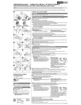
QuickPro® PUMP HEAD AND PUMP TUBE REPLACEMENT
Classic Series Double Head and Dual Head Dual Control Pumps
NOTICE: Before installing or servicing the pump, read the pump manual for all safety information and complete instructions. The pump is designed for installation and service by properly trained personnel.
In general, the steps outline how to remove the old tubes from both heads and then how each new tube is installed.
A
PUMP TUBE REPLACEMENT
I PREPARATION
➊ Follow all safety precautions prior to tube replacement.
➋ Prior to service, pump water or a compatible buffer solution through the pump and suction and discharge lines to remove chemical and avoid contact.
II REMOVE THE PUMP TUBE
Double Head
Adjustable Pump
Dual Head
Dual Control Pump
Innermost Pump Head
(roller assembly has
WHITE center hub)
Outermost Pump Head
(roller assembly has
BLACK center hub)
B
C
D
E
F
G
➊ Turn the pump off and unplug the power cord. On the adjustable model, ensure that the feed rate control is set to 10. Figure A
➋ Depressurize and disconnect the suction and discharge lines.
Outermost Head: Remove The Pump Tube
➌ Open the back and front of the latches on both sides of the head. Figure B
For CE pump only: Remove the safety screw on cover.
➍ Remove the tube housing cover and flip to use as a tool in the next step. Figure C
➎ Align the center of the inverted cover with the center of the roller assembly so that the three holes on the face of the cover align with the three knurled lugs on
the roller assembly. Position the cover feet near the tube fittings. Figure D
NOTE: The roller assembly needs to be collapsed to remove the tube.
➏ On the adjustable pump, hold the feed rate control securely. On the fixed output pump hold the pump motor securely. Use the tube housing cover as a wrench
and quickly (snap) rotate the cover counter-clockwise to collapse the roller assembly. The tube will no longer be pressed against the tube housing. Figure E
NOTE: Counter-clockwise is viewed from facing the head of the pump.
➐ Remove and discard the pump tube. Figure F
➑ Remove the roller assembly, and the tube housing. On the adjustable pump also remove the shaft. Set them aside to re-install later.
Innermost Head: Remove The Pump Tube
Dual Head Dual Control
➒ Double Head Adjustable
• Remove the feed rate control to access the Innermost pump head.
• Open the back & front of the latches on both sides of the head. Figure B
• Open the back & front of the latches on both sides of the head. Figure B
For CE pump only: Remove the safety screw on cover.
➓ Remove the innermost tube housing cover and flip to use as a tool in the next step. Figure C
⓫ Slide the innermost tube housing cover on the shaft and align the rivets with the three knurled lugs on the roller assembly. Figure D
⓬ On the adjustable model, hold the feed rate control securely. On the fixed output model hold the pump motor securely. Use the tube housing cover as a wrench
and quickly (snap) rotate the cover counter-clockwise to collapse the roller assembly. The tube will no longer be pressed against the tube housing wall. Figure E
NOTE: Counter-clockwise is viewed from facing of the pump.
⓭ Remove and discard the old pump tube. Figure F
⓮ Remove the roller assembly, and the tube housing. On the adjustable pump also remove the shaft. Set them aside to re-install later.
⓯ Use a non-citrus all-purpose cleaner to clean chemical residue from the tube housings, roller assemblies and covers.
⓰ Check the housings for cracks and replace, if cracked.
⓱ Ensure the rollers turn freely. Replace the roller assembly if the rollers are seized or worn or if there is a reduction or lack of output from the pump.
⓲ Reinstall the clean tube housing for the innermost pump head. On an adjustable model, also install the shaft.
⓳ Apply AquaShield® to the shaft tip.
⓴ Install the roller assembly.
NOTE: The innermost roller assembly has a white center hub.
III INSTALL THE PUMP TUBE, EXPAND THE ROLLER ASSEMBLY & CENTER THE PUMP TUBE
Innermost Head: Install The Pump Tube
➊ Ensure the power to the pump is off. On the adjustable model, ensure that the feed rate controls are set to 10. Figure A
➋ Place the new tube in the innermost pump head; use your fingers to center it over the rollers. Figure G
➌ Place the innermost tube housing cover on the innermost tube housing, affix the front latches to the over lip and then press the latches back to secure.
➍ With the cover latched, plug the pump in and turn the power on. Allow the pump to run the roller assembly in its collapsed position for approximately one
minute, to relax the tube.
➎ Turn the pump off and unplug the power cord.
➏ Remove the innermost head tube housing cover and flip to use as a tool in the next step. Figure C
➐ Slide the inverted cover on the shaft and align the rivets with the three knurled lugs on the roller assembly. Position the cover feet near the bottom. Figure H
NOTE: The roller assembly needs to be expanded so the tube is pressed against the tube housing wall.
➑ Expand roller assembly.
I
H
Double Head Adjustable & Dual Head Dual Control
J
K
L
M
• Hold the feed rate control securely, use the cover as a wrench and quickly
(snap) rotate the roller assembly clockwise to expand the roller assembly.
The tube will be pressed against the tube housing wall. Figure I & J
Proceed to step 9.
NOTE: Clockwise is viewed from facing the head of the pump.
Double Head Fixed
a. Slide one latch out to remove it from
R
S
the tube housing. Insert the latch end
into the keyed slot into the vent in the
rear of the motor housing. While
pressing the latch into the rear of the
motor, gently rotate the cover
clockwise until it stops. Figure R & S
b. Holding the pump securely, use the adapter cover as a wrench and quickly
(snap) rotate the roller assembly clockwise to expand the roller assembly.
The tube will be pressed against the tube housing wall. Figure I & J
NOTE: Clockwise is viewed from facing the head of the pump.
c. Remove the latch from the vent and re-attach it to the tube housing.
Proceed to step 9.
➒ Place the tube housing cover feet first on the tube housing, affix the front of the latches to the cover lip and then press the latches back to secure.
❿ With the cover latched, plug the pump in and turn it on. Allow the pump to run the roller assembly in its expanded position for approximately one minute to
PUMP HEAD REPLACEMENT
Innermost Pump Head
(roller assembly has WHITE center hub)
relax the tube.
⓫ Remove the relaxed tube from the innermost head (follow Outermost Head: Remove the Pump Tube steps 3-7) and set it aside to be installed in the
outermost head later.
⓬ Install a new pump tube in the innermost head (follow Innermost Head: Install the Pump Tube steps 1-10).
Innermost Head: Center The Pump Tube
⓭ Ensure the pump is off. Lift the latch located between the tube fittings, leaving the end of the latch engaged with the lip on the tube housing cover. Leave the
latch on the opposite side engaged. Figure L
⓮ Plug the pump in and turn it on. Turn the tube fitting on the suction side not more than 1/8 of a turn in the direction the tube must move. Figure M
⓯ Do not let go of the fitting until the tube rides approximately in center of the rollers.
⓰ Turn pump off, let go of the fitting, and secure the latch between the fittings.
For CE pump only: Reinstall the safety screw on the cover.
Outermost Head: Install The Pump Tube
Dual Head Dual Control
⓱ Double Head Adjustable
• Reinstall the feed rate control & insert the outermost shaft, confirm the feed
• Reinstall clean tube housing and roller assembly (with black center hub)
rate control setting is on #10.
for the outermost head.
• Reinstall clean tube housing and roller assembly (with black center hub)
for the outermost head.
⓲ Place the previously relaxed new tube in the outermost pump head; use your fingers to center it over the rollers.
⓳ Align the center of the inverted cover with the center of the roller assembly so that the three holes on the face of the cover align with the three knurled lugs on
I PREPARATION
➊ Follow all safety precautions prior to head replacement.
➋ Prior to service, pump water or a compatible buffer solution through
the pump and suction and discharge lines to remove chemical and
avoid contact.
II REPLACE THE PUMP HEAD
➊
➋
➌
➍
➎
Remove new pump head from package.
Unlatch both latches.
Remove the cover, pump tube & roller assembly and set aside.
Follow Pump Tube Replacement steps 1-12 and then continue with
steps 18-20.
Using new pump head parts, follow III INSTALL THE PUMP TUBE,
EXPAND THE ROLLER ASSEMBLY AND CENTER THE TUBE steps 1-26
from PUMP TUBE REPLACEMENT.
Stenner Pump Company
3174 DeSalvo Road
Jacksonville, Florida 32246 USA
Phone
US Toll Free
Fax
904.641.1666
800.683.2378
904.642.1012
www.stenner.com
[email protected]
© Stenner Pump Company
All Rights Reserved
⓴
the roller assembly. Position the cover feet near the bottom. Figure H
NOTE: The roller assembly needs to be expanded so the tube is pressed against the tube housing wall.
Expand the roller assembly.
Double Head Adjustable & Dual Head Dual Control
Double Head Fixed
a. Slide one latch out to remove it from
• Hold the feed rate control securely, use the cover as a wrench and quickly
R
S
the tube housing. Insert the latch end
(snap) rotate the roller assembly clockwise to expand the roller assembly.
into the keyed slot in the back of the
The tube will be pressed against the tube housing wall. Figure I & J
motor vent. While pressing the latch
Proceed to step 21.
into the rear of the motor, gently rotate
NOTE: Clockwise is viewed from facing the head of the pump.
the cover clockwise until it stops.
Figure R & S
b. Holding the pump securely, use the cover as a wrench and quickly (snap)
rotate the roller assembly clockwise to expand the roller assembly. The
tube will be pressed against the tube housing wall. Figure I & J
NOTE: Clockwise is viewed from facing the head of the pump.
c. Remove the latch from the vent and re-attach it to the tube housing.
Proceed to step 21.
Apply a small amount of AquaShield® to the cover bushing ONLY. DO NOT lubricate the pump tube.
Outermost Head: Center The Pump Tube
Place the tube housing cover (feet first) on the tube housing, affix the front of the latches to the cover lip and then press the latches back to secure. Figure K
Follow Innermost Head: Center The Pump Tube steps 13-16.
Inspect the suction and discharge lines, point of injection, and check valve duckbill for blockages. Clean and/or replace as required.
Reconnect the suction and discharge lines.
Turn the pump on and run for one minute to verify operation.
This information is not intended for specific application purposes. Stenner Pump Company reserves the right to make changes to prices, products, and specifications at any time without prior notice.
INSQPDH 0715
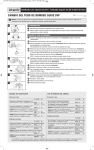
DODIFICADOR QuickPro® – CAMBIO DE CABEZAL Y DE TUBO DE BOMBEO
Serie Clásica Doble Cabezal y Serie Clásica Doble Controlador y Doble Cabezal
NOTICE: Lea todas las advertencias de seguridad detalladas en el manual de instalación antes de instalar o reparar su dosificador. El dosificador ha sido diseñado para ser instalado por personal entrenado debidamente.
En general, los pasos indican cómo remover los tubos de bombeo viejos de ambos cabezales y luego cómo cada tubo es instalado.
A
CAMBIO DEL TUBO DE BOMBEO
I PREPARACION
➊ Siga todas las precauciones de seguridad antes de cambiar el tubo.
➋ Antes de realizar el cambio, bombee una cantidad generosa de agua o solución neutral para limpiar todo residuo químico y evitar el contacto.
II QUITE EL TUBO DE BOMBEO VIEJO
➊ Apague el dosificador y desenchúfelo. En modelos de caudal ajustable; asegúrese que el anillo del controlador esté en el número 10. Ilustración A
➋ Purgue la presión y desconecte los tubos de succión y descarga.
Dosificador de
Doble Cabezal y
Caudal Ajustable
Dosificador de Doble
Cabezal y Doble
Controlador de Caudal
Cabezal Interior
(conjunto de rodillos tiene
centro de color BLANCO)
Cabezal Exterior
(conjunto de rodillos tiene
centro de color NEGRO)
C
B
Cabezal exterior: Quite el tubo
➌ Abra los ajustadores de ambos lados del cabezal. Ilustración B
Para dosificadores CE solamente: Quite el tornillo de seguridad de la cubierta del cabezal.
➍ Remueva la tapa del cabezal y voltéela para usar como herramienta en el próximo paso. Ilustración C
➎ Alinee el centro de la tapa volteada con el centro del conjunto de rodillos de manera que los tres agujeros en la tapa queden alineados con los tres remaches
en relieve del conjunto de rodillos. Posicione los pies de la tapa cerca de las conexiones de tubos. Ilustración D
Nota: El conjunto de rodillos debe estar contraído para poder remover el tubo.
➏ En dosificadores de caudal ajustable, sostenga el controlador de caudal firmemente. En los dosificadores de caudal fijo; sostenga el motor. Usando la tapa
como herramienta, gire la misma rápidamente (con un movimiento corto y veloz) contra reloj, para contraer el conjunto de rodillos. El tubo ya no estará
presionado contra el cabezal. Ilustración E
Nota: Contra reloj es visto del frente del cabezal.
➐ Remueva y descarte el tubo. Ilustración F
➑ Remueva el conjunto de rodillos y la carcasa del cabezal. En modelos ajustables, también remueva el eje y coloque todo a su costado para reinstalar más adelante.
Cabezal interior: Quite el tubo
Modelos de Doble Cabezal y Doble Controlador
➒ Modelos Ajustables de Doble Cabezal
• Remueva el controlador de caudal para poder acceder al cabezal interior.
• Abra los ajustadores de ambos lados del cabezal. Ilustración B
• Abra los ajustadores de ambos lados del cabezal. Ilustración B
Para dosificadores CE solamente: Quite el tornillo de seguridad de la cubierta del cabezal.
➓ Remueva la tapa del cabezal interior y voltéela para usar como herramienta en el próximo paso. Ilustración C
⓫ Deslice la tapa del cabezal en el eje y alinee el centro de la tapa volteada con el centro del conjunto de rodillos de manera que los tres agujeros en la tapa
E
D
⓬
⓭
⓮
⓯
⓰
⓱
⓲
⓳
⓴
G
F
queden alineados con los tres remaches en relieve del conjunto de rodillos. Ilustración D
En dosificadores de caudal ajustable, sostenga el controlador de caudal firmemente. En los dosificadores de caudal fijo; sostenga el motor. Usando la tapa
como herramienta, gire la misma rápidamente (con un movimiento corto y veloz) contra reloj, para contraer el conjunto de rodillos. El tubo ya no estará
presionado contra el cabezal. Ilustración E
Nota: Contra reloj es visto del frente del cabezal.
Remueva y descarte el tubo. Ilustración F
Remueva el conjunto de rodillos y la carcasa del cabezal. En modelos ajustables, también remueva el eje y coloque todo a su costado para reinstalar más adelante.
Use un limpiador multiuso no-cítrico para limpiar los residuos químicos del cabezal, rodillos y tapa.
Revise si hay quebraduras en la carcasa y cámbiela si es necesario.
Asegúrese que los rodillos giran libremente. Cambie el conjunto de rodillos si los mismos están trancados o desgastados o si nota una reducción de caudal.
Reinstale la carcasa limpia del cabezal interior. En modelos ajustables, instale el eje también.
Aplique grasa a la punta del eje.
Instale el conjunto de rodillos.
Nota: El conjunto de rodillos del cabezal interior, tiene un centro blanco.
III INSTALE EL TUBO, EXPANDA EL CONJUNTO DE RODILLOS Y CENTRE EL TUBO
H
I
J
K
L
M
REEMPLAZO DEL CABEZAL
DEL DOSIFICADOR
Cabezal Interior
(conjunto de rodillos tiene centro de color BLANCO)
Cabezal Interior: Instale el tubo
➊ Asegúrese que el dosificador esté desenchufado. En modelos ajustables, asegúrese que el anillo esté en el número 10. Ilustración A
➋ Coloque el tubo nuevo en el cabezal interior. Utilice sus dedos para centrarlo en los rodillos. Ilustración G
➌ Coloque la tapa del cabezal interior y cierre los sujetadores de ambos lados.
➍ Con la tapa instalada, prenda el dosificador y déjelo prendido con el conjunto de rodillos contraídos, por un minuto para relajar el tubo de bombeo.
➎ Apague el dosificador y desenchúfelo.
➏ Remueva la tapa del cabezal y voltéela para usar como herramienta en el próximo paso. Ilustración C
➐ Deslice la tapa del cabezal en el eje y alinee el centro de la tapa volteada con el centro del conjunto de rodillos de manera que los tres agujeros en la tapa queden
alineados con los tres remaches en relieve del conjunto de rodillos. Ilustración H
Nota: El conjunto de rodillos debe estar expandido para presionar el tubo contra las paredes del cabezal.
➑ Expanda el conjunto de rodillos
Modelos Ajustables de Doble Cabezal y De Doble Cabezal y
Doble Controlador
Modelos Fijos de Doble Cabezal
a. Deslice y remueva un sujetador de la
• Sostenga el controlador de caudal firmemente, utilice la tapa como
S
R
carcasa del cabezal. Inserte el extremo
herramienta y gire la misma rápidamente (movimiento corto y veloz) en
deslizado en la ranura de la parte
dirección del reloj, para expandir los rodillos. El tubo estará presionado
trasera del motor. Mientras mantiene el
contra las paredes del cabezal. Ilustración I & J Proceda al paso 9.
sujetador en la ranura, gire la tapa
Nota: Dirección del reloj es visto desde el frente del cabezal.
suavemente en dirección del reloj hasta
que se detenga. Ilustración R & S
b. Sostenga el dosificador con firmeza y gire la tapa de forma rápida
(movimiento corto y veloz) en dirección del reloj, para expandir los
rodillos. El tubo quedará presionado contra las paredes del cabezal.
Ilustración I & J
Nota: Dirección del reloj es visto desde el frente del cabezal.
C. Remueva el sujetador de la ranura del motor y reinstale en su lugar, en la
carcasa del cabezal. Proceda al paso 9.
➒ Coloque la tapa del cabezal interior y cierre los sujetadores de ambos lados.
❿ Con la tapa instalada, penda el dosificador y déjelo prendido con el conjunto de rodillos contraídos, por un minuto para relajar el tubo de bombeo.
⓫ Remueva el tubo relajado del cabezal interior (siga las instrucciones Cabezal exterior: Quite el tubo, pasos 3 al 7) y colóquelo a su costado para ser
instalado en el cabezal exterior más adelante.
⓬ Instale un nuevo tubo de bombeo en el cabezal interior (siga las instrucciones Cabezal Interior: Instale el tubo, pasos 1 al 10).
Cabezal Interior: Centre el tubo de bombeo
⓭ Asegúrese que el dosificador esté apagado. Levante la parte trasera del sujetador que se encuentra entre las conexiones de tubos, dejando la parte delantera
del mismo enganchada en el labio de la carcasa. Deje el otro sujetador completamente cerrado. Ilustración L
⓮ Enchufe el dosificador y enciéndalo. Gire la conexión de tubo del lado de succión hacia donde desea deslizar el mismo (no más de 1/8 de giro). Ilustración M
⓯ NO suelte la conexión hasta que el tubo se encuentre centrado sobre los rodillos.
⓰ Apague el dosificador, suelte la conexión y cierre el sujetador colocado entre las conexiones.
Para dosificadores CE solamente: Reinstale el tornillo de seguridad en la tapa.
Cabezal Exterior: Instale el tubo de bombeo
Modelos de Doble Cabezal y Doble Controlador
⓱ Modelos Ajustables de Doble Cabezal
• Reinstale el controlador de caudal e inserte el eje exterior; confirme que el
• Reinstale la carcasa limpia y el conjunto de rodillos (con centro de color
anillo del controlador se encuentre en 10.
negro) del cabezal exterior.
• Reinstale la carcasa limpia y el conjunto de rodillos (con centro de color
negro) del cabezal exterior.
⓲ Coloque el tubo relajado previamente en el cabezal exterior; utilice sus dedos para centrarlo en los rodillos.
⓳ Alinee el centro de la tapa volteada con el centro del conjunto de rodillos de manera que los tres agujeros en la tapa queden alineados con los tres remaches
I PREPARACION
➊ Siga todas las precauciones de seguridad antes de cambiar el cabezal.
➋ Antes de realizar el cambio, bombee una cantidad generosa de agua o
solución neutral para limpiar todo residuo químico y evitar el contacto.
II REEMPLAZO DEL CABEZAL
➊ Remueva el nuevo cabezal del paquete.
➋ Abra ambos sujetadores.
➌ Remueva la tapa, el tubo y el conjunto de rodillos y colóquelos a
un costado.
➍ Siga los pasos indicados en esta página del 1 al 12 y luego continúe
➎
del 18 al 20.
Utilizando los componentes de cabezal nuevos, siga las instrucciones
III INSTALE EL TUBO, EXPANDA EL CONJUNTO DE RODILLOS Y
CENTRE EL TUBO, pasos 1 al 26.
Stenner Pump Company
3174 DeSalvo Road
Jacksonville, Florida 32246 USA
Tel
Línea gratuita
(USA y Canadá)
Fax
904.641.1666
800.683.2378
904.642.1012
www.stenner.com
[email protected]
© Stenner Pump Company
Derechos Reservados
⓴
en relieve del conjunto de rodillos. Posicione los pies de la tapa cerca de las conexiones de los tubos. Ilustración H
Nota: El conjunto de rodillos debe estar expandido para presionar el tubo contra las paredes del cabezal.
Expanda el conjunto de rodillos.
Modelos Ajustables de Doble Cabezal
Modelos Fijos de Doble Cabezal
a. Deslice y remueva un sujetador de la
• Sostenga el controlador de caudal firmemente, utilice la tapa como
R
S
carcasa del cabezal. Inserte el extremo
herramienta y gire la misma rápidamente (movimiento corto y veloz) en
deslizado en la ranura de la parte
dirección del reloj, para expandir los rodillos. El tubo estará presionado
trasera del motor. Mientras mantiene el
contra las paredes del cabezal. Ilustración I & J Proceda al paso 21.
sujetador en la ranura, gire la tapa
Nota: Dirección del reloj es visto desde el frente del cabezal.
suavemente en dirección del reloj hasta
que se detenga. Ilustración R & S
b. Sostenga el dosificador con firmeza y gire la tapa de forma rápida
(movimiento corto y veloz) en dirección del reloj, para expandir los rodillos. El
tubo quedará presionado contra las paredes del cabezal. Ilustración I & J
Nota: Dirección del reloj es visto desde el frente del cabezal.
c. Remueva el sujetador de la ranura del motor y reinstale en su lugar, en la
carcasa del cabezal. Proceda al paso 21.
Aplique una pequeña cantidad de grasa AquaShield® al cojinete de la tapa SOLAMENTE. NO lubrique el tubo de bombeo.
Cabezal Exterior: Centre el tubo de bombeo
Coloque la tapa del cabezal exterior y cierre los sujetadores de ambos lados. Ilustración K
Siga las instrucciones del Cabezal Interior: Centre el tubo de bombeo del paso 13 al 16.
Inspeccione los tubos de succión y descarga, el punto de inyección y la válvula de inyección, por si hay algún bloqueo. Limpie o reemplace si es necesario.
Reconecte los tubos de succión y descarga.
Prenda el dosificador por un minuto para verificar su funcionamiento.
La información en este folleto no está destinada a aplicaciones específicas. Stenner Pump Company se reserva el derecho a realizar cambios en precios, productos y especificaciones en cualquier momento y sin previo aviso.
INSQPDH 0715