1
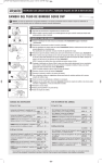
QuickPro® PUMP HEAD REPLACEMENT
for Single Head Adjustable & Fixed Output Pumps
NOTICE: Before installing or servicing the pump, read the pump manual for all safety information and complete instructions. The pump is designed for
installation and service by properly trained personnel.
A
B
REMOVE AND INSTALL THE QuickPro® PUMP HEAD
➊ Turn off the pump and unplug the power cord.
C
D
E
F
Adjustable Model
a. To remove the pump head, hold the feed rate securely, grasp the
head and turn it clockwise until it stops. Figure A
b. Remove the head by pulling it straight out from the pump. The
main shaft will come out with the pump head.
c. Using a pair of pliers, grasp the main shaft and rock it back and
forth (clockwise and counter-clockwise) while pulling it straight
out of the pump head. Set aside the shaft to be reinstalled later.
Discard the old tube, housing and cover. If the shaft will not come
out, remove the cover from the pump head and use a hammer to
tap the shaft from the front of the roller assembly to dislodge it.
Figure B & C
d. Insert the shaft back into the feed rate control. Figure D
e. Put the new pump head onto the feed rate control and turn it
counterclockwise until the shaft falls into place. Proceed to step 2.
Fixed Output Model
a. To remove the pump head, hold the pump securely, grasp the head
and turn it clockwise until it stops. Figure A
b. Remove the tube housing and roller assembly together by pulling
it straight out from the pump. The shaft will remain in the pump.
Discard the tube, housing and cover. If the housing and roller
assembly are difficult to remove, insert a large, flat blade
screwdriver between the pump body and the head. Gently pry
the head forward, ensuring the rivets on the pump body remain
disengaged from the tube housing.
c. Put the new pump head onto the motor and turn it counterclockwise
until the shaft falls into place. Figure E Proceed to step 2.
➋ Push the pump head in while turning it counterclockwise. Line up the rivet holes on the pump head with the rivets on the feed rate control (adjustable
pump) OR motor (fixed output pump). Figure E
➌ Continue to push until the rivets are inside the holes.
➍ Turn the pump head counterclockwise to secure the rivets in the rivet slots, firmly attaching the pump head.
EXPAND THE ROLLER ASSEMBLY
➊ On the adjustable model, ensure the feed rate control is set to 10. With the cover latched, plug the pump in and turn the power on. Allow the pump to run
the roller assembly in its collapsed position for approximately one minute to relax the tube. Figure F
➋ Turn the pump off and unplug the power cord.
➌ Remove the tube housing cover and flip to use as a tool in the next step. Figure G
➍ Align the center of the inverted cover with the center of the roller assembly so that the three holes on the face of the cover align with the three knurled lugs
G
➎
H
I
J
K
on the roller assembly. Position the cover feet near the bottom. Figure H
NOTE: The roller assembly needs to be expanded so the tube is pressed against the tube housing wall.
Expand the roller assembly.
Fixed Output Model (motor vent with key
Fixed Output Model (manufactured before
Adjustable Model
04/29/11)
slot, manufactured after 04/29/11)
• Hold the feed rate control securely, use the
a. Slide one latch out to remove it from the
Only the Stenner fan
cover as a wrench and quickly (snap)
tube housing. Insert the latch end into the
brake tool should be used for this step.
rotate the roller assembly clockwise to
key
slot in the vent in the rear of the
a. Insert the fan brake tool into the vent in
expand the roller assembly. The tube will
motor
housing. While pressing the latch
the rear of the motor housing. Refer to
be pressed against the tube housing wall.
into
the
rear of the motor, gently rotate
the figures below.
Figure I Proceed to step 6.
the
cover
clockwise until it stops. Refer to
NOTE: The fixed output pump doesn’t
NOTE: Clockwise is viewed from facing the
the
figures
below.
have a clutch so the fan brake keeps the
head of the pump.
b.
Holding
the
pump securely, use the cover
shaft from rotating when expanding the
as
a
wrench
and quickly (snap) rotate the
roller assembly.
roller
assembly
clockwise to expand the
b. Holding the pump securely, use the cover
roller
assembly.
The tube will be pressed
as a wrench and quickly (snap) rotate the
against
the
tube
housing wall. Figure I
roller assembly clockwise to expand the
&
J
roller assembly. The tube will be pressed
NOTE: Clockwise is viewed from facing the
against the tube housing wall. Figure I & J
head
of the pump.
NOTE: Clockwise is viewed from facing the
c.
Remove
the latch from the vent and rehead of the pump.
attach
it
to the tube housing. Proceed to
c. Remove the fan brake tool. Proceed to
step
6.
step 6.
L
➏ Place the tube housing cover on the tube housing, affix the front of the latches to the cover lip and then press the latches back to secure. Figure K
CENTER THE TUBE
➊ Ensure the pump is off. Lift the latch located between the tube fittings, leaving the end of the latch engaged with the lip on the tube housing cover.
M
N
➋
➌
➍
➎
Leave the latch on the opposite side engaged. Figure L
Plug the pump in and turn it on. Turn the tube fitting on the suction side not more than 1/8 of a turn in the direction the tube must move. Figure M
DO NOT let go of the fitting until the tube rides approximately in center of the rollers.
Turn pump off, let go of the fitting, and secure the latch between the fittings. Figure N
Turn the pump on and run for one minute to verify operation.
INSQPPH 0815
Stenner Pump Company
3174 DeSalvo Road
Jacksonville, Florida 32246 USA
Phone
US Toll Free
Fax
904.641.1666
800.683.2378
904.642.1012
www.stenner.com
[email protected]
© Stenner Pump Company All Rights Reserved
CAMBIO DEL CABEZAL QuickPro®
para Dosificadores de un Cabezal de Caudal Ajustable y Fijo
NOTICE: Lea todas las advertencias de seguridad detalladas en el manual de instalación antes de instalar o reparar su dosificador. El dosificador ha
sido diseñado para ser instalado por personal entrenado debidamente.
A
B
INSTALACION DEL CABEZAL QuickPro®
➊ Apague el dosificador y desenchufe.
C
D
Modelos de Caudal Ajustable
a. Para quitar el cabezal, sostenga el controlador de caudal y gire el cabezal
en el sentido de las agujas del reloj hasta que se detenga. Ilustración A
b. Tire del cabezal para separarlo del controlador de caudal. El eje
saldrá junto con el cabezal.
c. Utilizando un alicate o pinza, tire del eje, girándolo en ambos
sentidos (en contra y con el reloj) para separarlo del cabezal.
Colóquelo a un costado para instalarlo nuevamente más adelante.
Descarte el tubo, carcasa y tapas viejas. Si el eje no se separa, quite
la tapa del cabezal y utilice un martillo para golpear suavemente al
eje (del lado de los rodillos) y aflojarlo. Ilustración B & C
d. Inserte el eje en el controlador de caudal. Ilustración D
e. Coloque el cabezal deslizándolo en el eje y gírelo en sentido
contrario al reloj hasta que el eje caiga en su lugar. Proceda al paso 2.
Modelos de Caudal Fijo
a. Para quitar el cabezal, sostenga el motor y gire el cabezal en el sentido
de las agujas del reloj hasta que se detenga. Ilustración A
b. Quite el cabezal tirando derecho y separándolo del dosificador. El eje
permanecerá en su lugar. Descarte el tubo, la carcasa y la tapa. Si le
resulta difícil remover el cabezal, inserte un destornillador de punta
plana entre el cabezal y el motor y utilícelo con cautela como palanca
para separar los componentes. Asegúrese los remaches del motor
permanecen desacoplados del cabezal.
c. Coloque el nuevo cabezal en el motor y gírelo en sentido contrario al
reloj hasta que el eje caiga en su lugar. Ilustración E Proceda al
paso 2.
➋ Presione el cabezal mientras lo gira en sentido contrario al reloj. Alinee los agujeros en el cabezal con los remaches en el controlador de caudal
(dosificadores de caudal ajustable) o el motor (dosificadores de caudal fijo). Ilustración E
E
F
➌ Presione hasta que los remaches queden insertados en los agujeros.
➍ Gire el cabezal en sentido contrario al reloj hasta trancar los remaches y asegurando que quede firmemente instalado.
EXPANDA EL CONJUNTO DE RODILLOS
➊ En modelos de caudal ajustable, asegúrese que el controlador de caudal esté colocado en 10. Con la tapa instalada, prenda el dosificador y déjelo
prendido, con el conjunto de rodillos contraídos, por un minuto, para relajar el tubo de bombeo. Ilustración F
➋ Asegúrese que el dosificador esté apagado y desenchufado.
➌ Remueva la tapa y voltéela para usar como herramienta en el próximo paso. Ilustración G
➍ Alinee el centro de la tapa volteada con el centro del conjunto de rodillos, de modo que los tres orificios en la cara de la tapa estén alineados con los tres
G
H
I
J
remaches en relieve del conjunto de rodillos. Coloque las patas de la tapa cerca de los extremos del tubo. Ilustración H
NOTA: El conjunto de rodillos debe estar expandido para presionar el tubo contra las paredes del cabezal.
➎ Expanda el conjunto de rodillos.
Modelos de Caudal Fijo
Modelos de Caudal Fijo
Modelos de Caudal Ajustable
(fabricados antes del 29 de Abril del 2011)
(fabricados después del 29 de Abril del 2011)
• Sujete el controlador de caudal, use la tapa
a. Deslice un sujetador de la carcasa del
Solamente el freno de
como herramienta y gire la misma de forma
cabezal. Inserte el extremo deslizado en la
ventilador hecho por Stenner debe usarse para
rápida (con un movimiento corto y veloz), en
ranura
de la parte trasera del motor. Mientras
este procedimiento
dirección del reloj, para expandir los rodillos.
mantiene
el sujetador en la ranura, gire la
a. Inserte el freno de ventilador en la parte
El tubo estará presionado contra las paredes
tapa
suavemente
en dirección del reloj hasta
trasera del motor. Vea las ilustraciones abajo.
del cabezal. Ilustración I Proceda al paso 6.
que
se
detenga.
Vea
las ilustraciones abajo
NOTA: El dosificador de caudal fijo no tiene
NOTA: Dirección del reloj es visto del frente
b.
Sostenga
el
dosificador
con firmeza y gire la
embrague y el freno de ventilador previene la
del cabezal.
tapa
de
forma
rápida
(con
un movimiento
rotación del eje cuando se expanden
corto
y
veloz),
en
dirección
del reloj, para
los rodillos.
expandir
los
rodillos.
El
tubo
estará
b. Sostenga el dosificador con firmeza y gire la
presionado
contra
las
paredes
del cabezal.
tapa de forma rápida (con un movimiento
Ilustración
I
&
J
corto y veloz), en dirección del reloj, para
NOTA: Dirección del reloj es visto del frente
expandir los rodillos. El tubo estará
del
cabezal.
presionado contra las paredes del cabezal.
c. Remueva el sujetador de la ranura del motor
Ilustración I & J
y reinstale en su lugar, en la carcasa del
NOTA: Dirección del reloj es visto del frente
cabezal.Proceda al paso 6.
del cabezal.
c. Remueva el freno de ventilador. Proceda al
paso 6.
K
L
➏ Reinstale la tapa del cabezal, conecte el frente de los sujetadores al reborde de la tapa y luego presiónelos para fijarlos. Ilustración K
CENTRE EL TUBO
➊ Asegúrese que el dosificador esté apagado. Levante la parte trasera del sujetador que se encuentra entre las conexiones del tubo, dejando el extremo
M
N
➋
➌
➍
➎
delantero enganchado en la tapa de la carcasa. Deje el otro sujetador completamente cerrado. Ilustración L
Enchufe el dosificador y enciéndalo. Gire la conexión de tubo del lado de succión hacia donde deba moverse (no más de 1/8 de giro). Ilustración M
No suelte la conexión hasta que el tubo llegue aproximadamente al centro de los rodillos.
Apague el dosificador, suelte la conexión y fije el sujetador que se encuentra entre las conexiones. Ilustración N
Prenda el dosificador por un minuto para verificar su funcionamiento.
INSQPPH 0815
Stenner Pump Company
3174 DeSalvo Road
Jacksonville, Florida 32246 USA
Tel
Fax
904.641.1666
904.642.1012
www.stenner.com
[email protected]
© Stenner Pump Company Derechos Reservados