1
5
Installation of Ceiling Grille Housing With
or Without Light
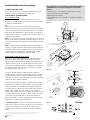
Figure 1
1. Plan Location of Inlet Grilles
Based on the bathroom layout and fixtures, plan the location of the ceiling
grilles for the most effective ventilation.
2. Securing the Housing to the Ceiling Joists
NEW CONSTRUCTION
ount housing directly to the ceiling joist using screws and keyhole slots.
M
Locator tabs on housing should be flush with the bottom edge of the ceiling
joist for correct positioning of the unit once drywall is installed (Figure 1).
OR
Use the hanger bars to suspend the housing between ceiling joists. For
correct positioning, hanger bars should be positioned 3/16" up from the
bottom edge of the ceiling joist on models with 4" duct connection and
15/ " up from bottom edge of joist on models with 6" duct connection. On
32
models with 4" duct, tighten anti-slide screws to keep hanger bars in place.
(Figure 2).
Postion Locator Tabs
flush with bottom
edge of joist
Figure 2
Note: Hanger bars on units with 4" duct connection can be used on ceiling
joists up to 24" on center. Hanger bars on units with 6" duct connection
span ceiling joists up to 16" on center.
Note: If drywall or ceiling material is thicker than 5/8" the locator tabs may
be removed to allow the grille collar to be flush with the finished ceiling
material. When ceiling drywall is being installed, cut hole for ceiling grille.
EXISTING CONSTRUCTION OR WHEN DRYWALL IS IN PLACE.
Cut a 6" round hole for the ceiling grille only and install the housing from the
attic (Figure 3). Place the housing against the ceiling joist using the locator
tabs to determine the correct position (Figure 1) or align it using the hanger
bars (Figure 2). Punch out the keyhole knockouts (if using) and the electrical
knockout if needed. To complete installation for Bath Fan models with lights,
continue with steps 3 through 5. For models without lights, skip to steps 4
and 5.
Housings with 4"
duct: 3/16" from
bottom edge of
joist.
Housings with 6"
duct: 15/32"
Anti-slide
locking screw
on models with
4" duct.
Figure 3
Figure 4
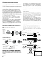
3. Make Electrical Connections to the Ceiling Grille Housing.
Remove the electrical cover inside the steel housing using a screwdriver.
Connect power by following wiring diagram (Figure 5) and following local or
National Electrical Codes. Replace the electrical cover.
4. Connect the Fan to the Ceiling Grille Housing(s).
Install appropriate diameter duct from the fan to the ceiling grille housing.
(Insulated flexible duct is recommended for all Fantech bathroom exhaust
applications for quieter operation.) For dual grille models, install duct between
fan and wye adapter* (included). Then, attach duct to each leg of the wye and
to each ceiling grille housing. Secure duct in place and seal. If using insulated
flexible duct, seal the inner liner to the duct connector then seal the outer shell
over the top of the inner liner. Do not leave the insulation material exposed.
5. Installing the Bulb.
Install the bulb by gently inserting it into the socket in the grille housing.
Install the grille by pushing it firmly into the steel collar until it is shouldered
by the ceiling drywall (Figure 3).
Repeat steps 1 through 5 for each additional ceiling grille housing being
installed.
Additional steps required when installing a fluorescent modelS PB110F,
PB270F-2 or PB270FV-2 over a tub or shower (Figure 4)
1. Place ring 1 on on socket legs first.
2. Screw metal shield in place over socket.
3. Add rubber gasket
4. Secure ring 2 to socket. Click indicates a secure installation.
Shield
Ring 2
Gasket
Screw
Ring 1
Grille
Fluorescent
lamp
SCALE 3/10
Socket
Figure 5
Electrical
*For most efficient operation wye adapter should be positioned
the equivalent of three duct diameters away from the fan inlet.
fantech