1
INSTALLATION INSTRUCTIONS
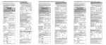
Brass
Compression
Nut
Brass
Insert
Poly
Tubing
Plastic
Ferrule
IL0707
23. For 2 tank softener installations only, make sure
you have the plastic ferrule in the right direction for
an air tight seal.
20. P
ress 1/2” I.D. semi-rigid or non-collapsible plastic
tubing (not included) onto drain line hose barb
until snug and secure with a hose clamp (not
included).
NOTE: Do not run 1/2” drain line over 20’. If over 20’,
increase tube size to 3/4”.
24. Visually check brine tubing for cracks or kinks.
Check fittings for proper assembly and tightness as
diagrammed.
21. Typical drain line to stand pipe with proper 4” air
gap.
NOTE: An air gap is required by most local plumbing
codes to prevent waste water back flow. Check and
follow your local codes.
25. Turn compression nut clockwise with wrench to
tighten.
CAUTION: Do not over tighten.
NOTE: This step is not required on single tank units.
If you are installing a single tank unit, proceed to step
28.
22. L
oosen compression nut located on right side of
control valve by turning counter clockwise. Insert
one end of 3/8” O.D. tube (included).
NOTE: This step has already been done on single tank
design units.
7