1
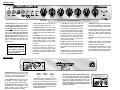
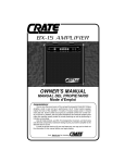
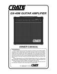
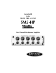
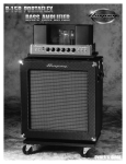
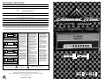
R-50H TECHNICAL SPECIFICATIONS
OUTPUT POWER RATING
SIGNAL TO NOISE RATIO
POWER REQUIREMENTS
GAIN
TREBLE
MID
BASS
TUBE COMPLEMENT
SIZE AND WEIGHT
50 Watts RMS @ 10 % THD 8 ohm load 120 VAC
65dB Typical
Domestic 100/120 VAC, 60 Hz, 115VA
Export:
100/115 VAC, 50/60 Hz, 115VA
230VAC, 50/60Hz, 115VA
60 dB Clean channel, 95 dB Overdrive channel
24 dB Range @ 5 kHz Clean channel
24 dB Range @2kHz Overdrive Channel
8 dB Range @ 700 Hz
24 dB Range @ 40 Hz
Power Amp: EL34 (2); Preamp: 12AX7A (3)
29.75”W x 11.25” H x 9.5”D, 34.2 lbs.
The R-50H is covered with a durable Tolex material: wipe it clean with a lint-free cloth. Never
spray cleaning agents onto the cabinet. Avoid abrasive cleansers which would damage the finish.
CAUTION
RISK OF ELECTRIC SHOCK
DO NOT OPEN
CAUTION: TO REDUCE THE RISK OF ELECTRIC SHOCK,
DO NOT REMOVE COVER.
NO USER-SERVICEABLE PARTS INSIDE.
REFER SERVICING TO QUALIFIED SERVICE PERSONNEL.
PRECAUCION
RIESGO DE CORRIENTAZO
NO ABRA
PRECAUCION PARA DISMINUOIR EL RIESGO DE CORRIENTAZO
NO ABRA LA CUBIERTA
NO HAY PIEZAS ADENTRO QUE EL USARIO PUEDO REPARAR
DEJE TODO MANTENIMIENTO A LOS TECHNICOS CALIFICADOS
THIS EQUIPMENT HAS BEEN
DESIGNED AND ENGINEERED
TO PROVIDE SAFE AND RELIABLE OPERATION. IN ORDER
TO PROLONG THE LIFE OF THE
UNIT AND PREVENT ACCIDENTAL DAMAGES OR INJURY,
PLEASE FOLLOW THESE PRECAUTIONARY GUIDELINES:
ESTE APARATO HA SIDO DISENADO Y CONSTRUIDO PARA
PROVEER ANOS DE OPERACION SEGURA Y CONFIABLE.
PARA PROLONGAR LA VIDA DE
ESTA UNIDAD E IMPEDIR
DANOS ACCIDENTALES POR
FAVOR SIGA ESTAS INSTRUCCIONES PREVENTIVAS:
CET ÉQUIPEMENT AVAIT ÉTÉ
INVENTÉ ET ARRANGÉ POUR
POURVOIR DES ANNÉES
D'USAGE SAUF ET SÛR. POUR
PROLONGER LA VIE DE CET
APPAREIL ET POUR EMPÊCHER
LES DOMMAGES ET LES TORTS
ACCIDENTELS, SUIVEZ LES
INSTRUCTIONS DE PRÉCAUTION.
CAUTION: TO REDUCE THE
RISK OF ELECTRIC SHOCK, DO
NOT OPEN CHASSIS; DO NOT
DEFEAT OR REMOVE THE
GROUND PIN OF THE POWER
CORD; CONNECT ONLY TO A
PROPERLY GROUNDED AC
POWER OUTLET.
PRECAUCION: PARA DISMINUIR
EL RIESGO DE DESCARGAS
ELECTRICAS: (1) NO ABRA LA
CUBIERTA, (2) NO ES
RECOMENDABLE REMOVER O
DESACTIVAR LA PATA DEL
POLO A TIERRA DEL CABLE DE
CORRIENTE, CONECTE CORRECTAMENTE A UNA TOMA DE
CORRIENTE A TIERRA.
AVERTISSEMENT: POUR
RÉDUIRE LES RISQUES D'ÉLECTROCUTION: (1) N’OUVREZ
PAS LE CHÂSSIS, (2) NE PAS
ESSAYER DE SUPPRIMER LA
BROCHE CORRESPONDANT À
LA TERRE.
WARNING: TO REDUCE THE
RISK OF FIRE OR ELECTRIC
SHOCK, DO NOT EXPOSE THIS
EQUIPMENT TO RAIN OR MOISTURE.
CAUTION: NO USER-SERVICEABLE PARTS INSIDE. REFER
SERVICING TO QUALIFIED SERVICE PERSONNEL.
ATTENTION
RISQUE D'ELECTROCUTION
NE PAS OUVRIR
ATTENTION: POUR REDUIRE D'ELECTROCUTION NE PAS
ENLEVER LE COUVERCLE. AUCUNE PIECE INTERNE N'EST REPRABLE
PAR L'UTILISATEUR. POUR TOUTE REPARATION, S'ADRESSER A UN
TECHNICIEN QUALIFIE.
VORSICHT
ELEKTRISCHE SCHLAGGEFAHR
NICHT OFFENEN
CAUTION: OUR AMPLIFIERS
ARE CAPABLE OF PRODUCING
HIGH SOUND PRESSURE LEVELS. CONTINUED EXPOSURE
TO HIGH SOUND PRESSURE
LEVELS CAN CAUSE PERMANENT HEARING IMPAIRMENT
OR LOSS. USER CAUTION IS
ADVISED AND EAR PROTECTION IS RECOMMENDED IF
UNIT IS OPERATED AT HIGH
VOLUME.
VORSICHT: ZUR MINIMIERUNG ELEKTRISCHER SCHLAGGEFAHR NICHT
DEN DECKEL ABENHMEN. INTERNE TEILE KONNEN NICHT VOM
BENUTZER GEWARTET WERDEN. DIE WARTUNG IS QUALIFIZIERTEM
WARTUNGSPERSONAL ZU UBERLASSEN.
EXPLANATION OF GRAPHICAL SYMBOLS:
=
EXPLICACION DE SIMBOLOS GRAFICOS:
EXPLICATION DES SYMBÔLES GRAPHIQUES:
"DANGEROUS VOLTAGE"
“VOLTAJE PELIGROSO”
"DANGER HAUTE TENSION"
"GEFAHLICHE SPANNUNG"
ADVERTENCIA: PARA EVITAR
DESCARGAS EL ECTRICAS O
PELIGRO DE INCENDIO, NO
DEJE ESTE APARATO
EXPUESTO A LA LLUVIA O
HUMEDAD.
PRECAUCION: NO HAY PIEZAS
ADENTRO QUE EL USUARIO
PUEDE REPARAR. DEJE TODO
MANTENIMIENTO A LOS TÉCNICOS CALIFICADOS.
PRECAUCION: NUESTROS
AMPLIFICADORES PUEDEN
PRODUCIR NIVELES DE PRESION DE SONIDO ALTO.
EXPOSICION CONTINUADA A
LOS NIVELES DE PRESION DE
SONIDO ALTO PUEDE CAUSA
DANO PERMANENTE A SU
OIDO. ES ACONSEJADO QUE
USE PRECAUCION AL USUARIO
Y ES RECOMENDADO PROTECCION PARA LOS OIDOS SI LA
UNIDAD ES OPERADA A VOLUMEN ALTO.
=
ATTENTION: POUR RÉDUIRE
LES RISQUES D'UN FEU OU
D'ÉLECTROCUTION, N’EXPOSEZ PAS L'APPAREIL À LA
PLUIE OU À LA MOITEUR.
ATTENTION: IL N'Y A PAS
D’ÉLÉMENTS RÉPARABLES
DANS L'APPAREIL. CONSULTER
UN TECHNICIEN QUALIFIÉ
POUR LES RÉPARATIONS.
ATTENTION: NOS AMPLIFICATEURS SONT CAPABLES DE LA
PRODUCTION DES NIVEAUX DE
SON D'UNE HAUTE PRESSION.
L'EXPOSITION CONTINUE AUX
CES NIVEAUX PEUT CAUSER
LA SURDITÉ PERMANENTE. LA
PRUDENCE EST ADVISÉ À UTILISATEUR ET LA PROTECTION
DES OREILLES EST RECOMMANDÉ SI L'APPAREIL EST
UTILISÉ À UN HAUT NIVEAU DE
VOLUME.
"IT IS NECESSARY FOR THE USER TO REFER TO THE INSTRUCTION MANUAL"
“ES NECESARIO QUE EL USUARIO SE REFIERA AL MANUAL DE INSTRUCCIONES.”
"REFERREZ-VOUS AU MANUAL D'UTILISATION"
"UNBEDINGT IN DER BEDIENUNGSANLEITUNG NACHSCHLAGEN"
Specs and other information subject to change without notice.
Ampeg is proudly Made in America. ©1997 SLM Electronics, 1400 Ferguson Avenue,
St. Louis, MO 63133 U.S.A.
P/N 47-277-15 • 02/97
;;;;;;;;;;;
yyyyyyyyyyy
;;;;;;;;;;;
yyyyyyyyyyy
;;;;;;;;;;;
yyyyyyyyyyy
;;;;;;;;;;;
yyyyyyyyyyy
;;;;;;;;;;;
yyyyyyyyyyy
;;;;;;;;;;;
yyyyyyyyyyy
;;;;;;;;;;;
yyyyyyyyyyy
;;;;;;;;;;;
yyyyyyyyyyy
;;;;;;;;;;;
yyyyyyyyyyy
;;;;;;;;;;;
yyyyyyyyyyy
;;;;;;;;;;;
yyyyyyyyyyy
;;;;;;;;;;;
yyyyyyyyyyy
;;;;;;;;;;;
yyyyyyyyyyy
;;;;;;;;;;;
yyyyyyyyyyy
;;;;;;;;;;;
yyyyyyyyyyy
;;;;;;;;;;;
yyyyyyyyyyy
THE FRONT PANEL:
15
1
2
3
4
5
6
7
8
9
10
BOTH CHANNELS
11
12
13
BOTH CHANNELS
14
CLEAN CHANNEL
OVERDRIVE CHANNEL
3. Power light indicates the amplifier is turned
on by glowing an iridescent blue color.
1. Power switch turns the main power on and
off. Always turn this switch on first, off last.
Turn the Standby switch (#2) on at least 30
seconds after turning on the Power switch.
4. Channel Select activates the clean channel
in the down position and the overdrive channel
in the up position. When a footswitch is connected (see #5), this switch is bypassed and has
no affect.
2. Standby switch activates the amplifier when
ready for play. Always turn this switch off
first, on last. Turn the Power switch (#1) on at
least 30 seconds before turning on the
Standby switch. During short breaks of use,
turn the Standby switch off, leaving the Power
switch on. This will help prolong the life of the
amplifier’s tubes.
5. Footswitch allows “remote control” of the
channel selection and reverb on/off. Insert the
stereo 1/4” plug of a two-button footswitch (such
as Ampeg’s AFP-2) here. The “tip” connection
controls channel switching, the “ring” controls
the reverb.
IMPORTANT! PLEASE NOTE:
Always connect the amplifier to
a suitable speaker cabinet and
set the Impedance switch (#18)
to the proper setting BEFORE
turning the amplifier on!
6. Line In serves as the “return” jack of an effect
loop, when connected to the output jack of a
floor pedal or rack-mounted processor. This jack
can double as a direct-into-the amplifier signal
feed when using the amp as a “slave” or extension amplifier.
7. Line Out serves as the “send” jack of an
effect loop, when connected to the input jack of
a floor pedal or rack-mounted processor. This
jack can double as a signal output for connecting directly to a house sound console, recording
console, powered monitor or external amplifier.
8. Reverb controls the amount of reverberation
applied to both channels. With the control at the
“0” position there is no reverb applied; as the
control is turned towards “10” the amount of
reverb increases accordingly.
9. Master controls the output volume level of the
overdrive channel. This control works with the
Gain control (#14) to produce sounds from
slightly distorted to screaming and everything in
between.
10. Bass adjusts the output level of the low frequencies for both channels. This control offers a
cut or boost of 24dB at 40Hz for both channels.
11. Mid adjusts the output level of the middle frequencies for both channels. This control offers a
cut or boost of 8dB at 700Hz for both channels.
12. Treble adjusts the output level of the high
frequency range for both channels. This control
offers a cut or boost of 24dB at 5kHz for the
clean channel, 24dB at 2kHz for the overdrive
channel.
13. Volume controls the output level of the clean
channel.
14. Gain sets the amount of overdrive distortion
for the overdrive channel. This control works
along with the Master control (#9).
15. Each Input accepts a standard 1/4” instrument plug from your electric guitar. The right
input is at 0dB level while the left input is padded
6dB to compensate for higher output sources.
THE REAR PANEL:
16
17
18
19
MODEL: R-50H
SERIAL: Q2ZZ650022
LINE: 120 V ~ 60
WATTS:
MAX
16. Main Speaker jack: Use this jack to connect
the amplifier to your speaker cabinet. Always use
this jack “first” – if using a second cabinet, connect it to the Extension Speaker jack (#17).
17. Ext. Speaker jack: Use this jack to connect
the amplifier to a second speaker cabinet –
always use the Main Speaker jack (#16) “first.”
18. Impedance switch: Use this switch to match
the amplifier to the TOTAL impedance of your
speaker cabinet(s). Use the following chart to
determine the total impedance (in parallel):
CABINET
IMPEDANCE
NUMBER OF
CABINETS
TOTAL
IMPEDANCE
16 ohms
2
8 ohms
19. AC Line In: Use the supplied power cord to
connect the amplifier to a suitable source of A.C.
voltage. This is a grounded, three-wire cord and
must be connected to a properly grounded outlet.
DO NOT attempt to defeat the ground connection of the power cord! See the serial number label for power ratings.
Hz
IMPORTANT NOTE ABOUT CERTAIN EXPORT UNITS:
In some areas 1/4” speaker jacks are not acceptable
for use on amplifiers capable of high output power
levels. For this reason the Speaker jacks on your
amplifier may resemble the illustration to the right.
Connect the amplifier to your speaker(s) using cables
rated for very high output power, terminated with the
appropriate connectors.