1
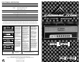
THE FRONT PANEL:
15
1
2
3
4
5
6
7
8
9
10
BOTH CHANNELS
11
12
13
BOTH CHANNELS
14
CLEAN CHANNEL
OVERDRIVE CHANNEL
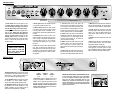
3. Power light indicates the amplifier is turned
on by glowing an iridescent blue color.
1. Power switch turns the main power on and
off. Always turn this switch on first, off last.
Turn the Standby switch (#2) on at least 30
seconds after turning on the Power switch.
4. Channel Select activates the clean channel
in the down position and the overdrive channel
in the up position. When a footswitch is connected (see #5), this switch is bypassed and has
no affect.
2. Standby switch activates the amplifier when
ready for play. Always turn this switch off
first, on last. Turn the Power switch (#1) on at
least 30 seconds before turning on the
Standby switch. During short breaks of use,
turn the Standby switch off, leaving the Power
switch on. This will help prolong the life of the
amplifier’s tubes.
5. Footswitch allows “remote control” of the
channel selection and reverb on/off. Insert the
stereo 1/4” plug of a two-button footswitch (such
as Ampeg’s AFP-2) here. The “tip” connection
controls channel switching, the “ring” controls
the reverb.
IMPORTANT! PLEASE NOTE:
Always connect the amplifier to
a suitable speaker cabinet and
set the Impedance switch (#18)
to the proper setting BEFORE
turning the amplifier on!
6. Line In serves as the “return” jack of an effect
loop, when connected to the output jack of a
floor pedal or rack-mounted processor. This jack
can double as a direct-into-the amplifier signal
feed when using the amp as a “slave” or extension amplifier.
7. Line Out serves as the “send” jack of an
effect loop, when connected to the input jack of
a floor pedal or rack-mounted processor. This
jack can double as a signal output for connecting directly to a house sound console, recording
console, powered monitor or external amplifier.
8. Reverb controls the amount of reverberation
applied to both channels. With the control at the
“0” position there is no reverb applied; as the
control is turned towards “10” the amount of
reverb increases accordingly.
9. Master controls the output volume level of the
overdrive channel. This control works with the
Gain control (#14) to produce sounds from
slightly distorted to screaming and everything in
between.
10. Bass adjusts the output level of the low frequencies for both channels. This control offers a
cut or boost of 24dB at 40Hz for both channels.
11. Mid adjusts the output level of the middle frequencies for both channels. This control offers a
cut or boost of 8dB at 700Hz for both channels.
12. Treble adjusts the output level of the high
frequency range for both channels. This control
offers a cut or boost of 24dB at 5kHz for the
clean channel, 24dB at 2kHz for the overdrive
channel.
13. Volume controls the output level of the clean
channel.
14. Gain sets the amount of overdrive distortion
for the overdrive channel. This control works
along with the Master control (#9).
15. Each Input accepts a standard 1/4” instrument plug from your electric guitar. The right
input is at 0dB level while the left input is padded
6dB to compensate for higher output sources.
THE REAR PANEL:
16
17
18
19
MODEL: R-50H
SERIAL: Q2ZZ650022
LINE: 120 V ~ 60
WATTS:
MAX
16. Main Speaker jack: Use this jack to connect
the amplifier to your speaker cabinet. Always use
this jack “first” – if using a second cabinet, connect it to the Extension Speaker jack (#17).
17. Ext. Speaker jack: Use this jack to connect
the amplifier to a second speaker cabinet –
always use the Main Speaker jack (#16) “first.”
18. Impedance switch: Use this switch to match
the amplifier to the TOTAL impedance of your
speaker cabinet(s). Use the following chart to
determine the total impedance (in parallel):
CABINET
IMPEDANCE
NUMBER OF
CABINETS
TOTAL
IMPEDANCE
16 ohms
2
8 ohms
19. AC Line In: Use the supplied power cord to
connect the amplifier to a suitable source of A.C.
voltage. This is a grounded, three-wire cord and
must be connected to a properly grounded outlet.
DO NOT attempt to defeat the ground connection of the power cord! See the serial number label for power ratings.
Hz
IMPORTANT NOTE ABOUT CERTAIN EXPORT UNITS:
In some areas 1/4” speaker jacks are not acceptable
for use on amplifiers capable of high output power
levels. For this reason the Speaker jacks on your
amplifier may resemble the illustration to the right.
Connect the amplifier to your speaker(s) using cables
rated for very high output power, terminated with the
appropriate connectors.