1
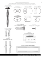
9316GT
v2_0913A
INSTALLATION GUIDE
BE SURE TO READ THE ENTIRE MANUAL. IF AT ANY TIME YOU ARE UNCLEAR ABOUT
THE DIRECTIONS AND BELIEVE YOU NEED FURTHER ASSISTANCE, CONTACT
GENERATIONS™ INSTALLATION EXPERTS AT 888-779-1543 FROM 9AM – 5PM EST.
PRECAUTIONS
• THIS PRODUCT SHOULD NEVER BE MOUNTED TO METAL FRAMING STUDS.
• WOOD STUDS SHOULD BE 2" X 4", AT MINIMUM: 1.5" X 3.5" (38 MM X 89 MM). DESIGNED
TO BE MOUNTED TO 2" X 4" WOOD STUDS THAT ARE SPACED 16" ON CENTER.
• THIS MOUNTING BRACKET WAS DESIGNED TO BE INSTALLED AND UTILIZED ONLY AS
SPECIFIED IN THIS MANUAL. GENERATIONS™ WILL NOT BE RESPONSIBLE FOR FAILURE
TO ASSEMBLE AS DIRECTED OR FOR THE IMPROPER ASSEMBLY, USE, OR HANDLING OF
THIS PRODUCT.
• IMPROPER INSTALLATION OF THIS PRODUCT MAY CAUSE DAMAGE OR SERIOUS INJURY.
GENERATIONS™ CANNOT BE LIABLE FOR DIRECT OR INDIRECT DAMAGE OR INJURY
CAUSED BY INCORRECT MOUNTING, INCORRECT USE, OR INCORRECT ASSEMBLY.
• IF THE MOUNTING BRACKET WILL BE ATTACHED TO ANY STRUCTURE OTHER THAN
THOSE SPECIFIED IN THIS MANUAL, ONLY A LICENSED PROFESSIONAL CONTRACTOR/
INSTALLER SHOULD PERFORM THIS INSTALLATION. THE SUPPORTING STRUCTURE
MUST SUPPORT, AT MINIMUM, FOUR TIMES THE COMBINED WEIGHT OF THE
MOUNTING BRACKET AND TV. IT IS THE RESPONSIBILITY AND LIABILITY OF THE
INSTALLER TO ENSURE THE SUITABILITY OF THE SUPPORTING STRUCTURE.
• CHECK CAREFULLY TO ENSURE THAT THERE ARE NO MISSING OR DAMAGED PARTS.
NEVER USE DEFECTIVE PARTS. IF ANY PARTS ARE DAMAGED OR MISSING, CALL
CUSTOMER SERVICE AT 888-779-1543 AND PARTS WILL BE SHIPPED DIRECTLY TO THE
ORIGINAL PURCHASER. PLEASE CONTACT CUSTOMER SERVICE BEFORE ATTEMPTING
TO RETURN PRODUCTS TO THE POINT OF PURCHASE.
• SPECIFICATIONS ARE SUBJECT TO CHANGE WITHOUT NOTICE.
• THE MAXIMUM WEIGHT OF YOUR TELEVISION CANNOT EXCEED THE MAXIMUM
WEIGHT RATING OF YOUR MOUNT OR ANY ATTACHED UL LISTED ADAPTERS SOLD
SEPARATELY, WHICHEVER IS LOWER.
NEVER EXCEED THE MAXIMUM LOAD CAPACITY OF 200 LBS (91 KG)
PARTS INCLUDED IN THIS KIT
(WP) 9316GT Wall Plate, Quantity: 1
(MA) Monitor Arms,
Quantity: 2
(IT) Installation Template,
Quantity: 1
(EC) End Covers,
Quantity: 2
(AB) M4 x 10mm
Security Screw, Quantity: 2
(D) M4/M5 Short
Spacer, Quantity: 4
(Q) M6/M8 Short
Spacer, Quantity: 4
(U) TOGGLER® brand
AF8 ALLIGATOR® Anchor, Quantity: 4
(E) M4/M5 Long
Spacer, Quantity: 4
(P) M6/M8 Long
Spacer, Quantity: 4
(R) M4/M5 Washer,
Quantity: 4
(S) M6/M8 Washer,
Quantity: 4
(T) #14 x 65mm Lag Bolt,
Quantity: 4
TOGGLER® brand ALLIGATOR® SOLID-WALL ANCHORS are patented under one or more of US Patent numbers 5,161,296 and 5,938,385; and foreign counterparts thereof and of 4,752,170.
Other patents pending. TOGGLER and ALLIGATOR are worldwide registered trademarks of Mechanical Plastics Corporation.
2
PARTS INCLUDED IN THIS KIT (CONTINUED)
(A) M4 x 12mm
TV Mounting Screw, Quantity: 4
(J) M6 x 14mm
TV Mounting Screw, Quantity: 4
(B) M4 x 22mm
TV Mounting Screw, Quantity: 4
(K) M6 x 25mm
TV Mounting Screw, Quantity: 4
(C) M4 x 30mm
TV Mounting Screw, Quantity: 4
(L) M6 x 35mm
TV Mounting Screw, Quantity: 4
(G) M5 x 12mm
TV Mounting Screw, Quantity: 4
(M) M8 x 20mm
TV Mounting Screw, Quantity: 4
(H) M5 x 22mm
TV Mounting Screw, Quantity: 4
(N) M8 x 30mm
TV Mounting Screw, Quantity: 4
(I) M5 x 30mm
TV Mounting Screw, Quantity: 4
(O) M8 x 40mm
TV Mounting Screw, Quantity: 4
TOOLS YOU WILL NEED
Screwdriver
Stud Finder
Drill
Drill Bit
Pencil
For wood 5/32" (4mm)
For masonry 5/16" (8mm)
Metric Ratchet
Set (Optional)
Masking Tape
Tape Measure
Level
3
1. ATTACHING THE ADJUSTABLE ARMS
Attaching the Monitor Arms
Attach each Monitor Arm (MA) to the back of the TV as shown in Figures 1 and 2. Make sure the the arms are
oriented properly, with the adjustment levers facing toward the outer edge of the TV so you can reach them later.
Also make sure that each Washer (R for M4 or M5 screws, or S for M6 or M8 screws) is placed between the
screw and the monitor arm. Don’t place the washers between the arms and the TV.
Don’t use screws that are too long because they will not fully seat in the holes and can permanently damage
the TV or mounting holes and cause the monitor to come loose.
Figure 1
DETAILED VIEW
MA
Back of TV
R or S
Selected Screw
Adjustment Lever
4
Use spacers in situations when the arms do not fit firmly against the back of the television, such as when the
back of the television is curved, contains larger recessed mounting holes, or some other obstruction is in the
way. This kit includes longer mounting screws and Spacers for such instances. The spacer you select must stick
out past the back of the TV to ensure secure mounting. You don’t want the spacer to be loose. The Monitor Arms
(MA) need to rest securely on the spacers. Test several of the spacers included in this kit to find the correct
match for the recessed holes in the back of your TV.
Figure 2
DETAILED VIEW
Selected Spacer
MA
Back of TV
R or S
Selected Screw
5
2. SECURING THE WALL PLATE
Finding the wood studs*
Wood
Stud
Using a stud finder,
determine the exact
location of the studs to
which you want to attach
the Wall Plate (WP).
Figure 3
After you determine the
stud locations, mark the
right and left sides of each
stud as shown in Figure 3.
* Wood studs must be a minumum of 1.5" X 3.5" (38 mm X 89 mm)
Determining the location of the TV
Measure the distance from the center of the monitor arms to the top and bottom of the TV to help determine the desired
height of the TV on your wall. The reason that you need to take these measurements is because many TVs do not have the
mounting location centered on the back of the monitor. To determine the exact height you want to mount the brackets,
use the convenient Installation Template (IT) rather than holding the TV in place while you do all this measuring. Always
make sure to use a level when placing the template. Measure from the floor up as shown in Figure 4, and using a pencil,
make small marks on the wall to help you determine the desired TV height.
Desired Location of TV
Level
IT
Distance from
Bottom of TV
to Center of
Monitor Arms
16
Inches
(406mm)
6
Height to bottom of TV
Figure 4
Wood
Studs
Using the Installation Template
The Installation Template (IT) included in this kit helps you select the correct positions for drilling the holes for
the TV mounting.
Figure 5
Lines for Locating Stud Markings
Line up the installation template with your stud markings to ensure the proper location for your drill holes. After you
have the position selected, tape the template in place securely on the wall with masking tape so that you don’t damage
the wall surface. Use a level to double check that the screw holes will line up vertically. Drill four evenly spaced holes 2.5"
(64mm) deep using a 5/32" (or 4mm) size drill bit. Follow the directions on the installation template carefully.
You must be careful to accurately drill the holes or else the screws may not line up with the holes in your
Wall Plate (WP).
Installing the Security Screws
Before you attach the Wall Plate (WP) to the wall, you need to insert the M4 x 10mm Security Screws (AB) into
the locking mechanism on each end of the bracket. Insert them only half-way, so that the locking arm can still be
easily rotated.
WP
DETAILED VIEW
Figure 6
AB
7
When mounting to a wood stud
When you have prepared the holes for mounting the Wall Plate (WP), place the plate over the holes and screw in the
Lag Bolts (T), as shown in Figure 7. After making sure the wall mount is level, tighten all of the lag bolts completely.
Figure 7
Supporting
Stud
WP
Supporting
Stud
Wall
T
Tighten the Lag Bolts (T) so that the Wall Plate (WP) is firmly attached to the wall, but don’t over-tighten!
The lag bolts and/or the supporting surface can become damaged, which greatly reduces their holding ability.
Final tightening of the bolts should always be done by hand, with a Phillips-head screwdriver or ratchet wrench.
When mounting to solid concrete, bricks, or cinder block
After you have determined your desired TV location, tape the Installation Template (IT) in place securely on the wall
with masking tape. Use a level to double check that the screw holes line up vertically, as shown in Figure 8.
Level
Figure 8
Line up the installation
template to ensure you’re
not going to drill into any
mortar joints. Drill four
evenly spaced holes 3"
(76mm) deep using a 5/16"
(or 8mm) size drill bit.
Follow the directions on
the installation template
carefully. Do not drill into
mortar joints!
8
IT
Concrete Block Wall
After the holes are drilled,
remove the template and
place four ALLIGATOR®
Anchors into the concrete
wall as shown in Figure 9.
U
Figure 9
After you have prepared the holes for mounting the Wall Plate (WP), install the wall plate by inserting the four Lag
Bolts (T) through the mount and into the ALLIGATOR® Anchors (U) as shown in Figures 7 and 10. After checking
that the wall plate is level, tighten all lag bolts fully, but be careful not to over-tighten.
T
Figure 10
U
3" (76mm)
minimum hole depth
Concrete
WP
Installing the Decorative End Covers
This kit includes decorative End Covers (EC) to make your bracket installation look clean and finished. Line up
the cover with the end of the bracket, and press into place. Look for two holes in the frame of the bracket, which
the end cover inserts into, as shown in Figure 11.
Figure 11
WP
EC
9
3. MOUNTING THE TV
Understanding the locking mechanism
Your wall mount has a unique feature which enables you to easily lock the Monitor Arms (MA) onto the Wall Plate
(WP) so that your TV cannot be removed. Before attempting to attach the TV with the monitor arms to the wall
bracket, make sure that the right
and left side locking mechanisms
are in the unlocked position.
Using a screwdriver, turn the large
screw head on the side of the
bracket 90° toward the front of the
bracket, as shown in Figure 12.
Figure 12
To Unlock
Large Screw
Head
Locking Bar
Shown Up in
Unlocked Position
Mounting the TV
Before you attempt to attach the TV to the Wall Plate (WP),
make sure the adjustable arms are parallel to the TV
(in the 0-degree position). This position is indicated by the
markings on the arms as shown in Figure 13B. Detailed
instructions on how to adjust the arms can be found in Figures
15 & 16.
MA
With an assistant, lift the TV and guide the monitor arms
onto the wall plate as shown in Figure 13A.
DETAILED VIEW
WP
Figure 13B
Markings on the
adjustable arm will line
up when in the 0-degree
position.
10
Figure 13A
Make sure the arms are engaged on both
the top and bottom rails of the wall plate!
Locking the arms into place
After the TV with the Monitor Arms (MA) is positioned on the Wall Plate (WP), you need to lock the arms into
place so that the TV cannot come off the wall plate or be removed. To lock the arms, turn the large screw head on
the side of both of the bracket’s locking mechanisms 90° toward the wall using a screwdriver as your assistant holds
the TV in place. (See Figure 14.) After the locking mechanism has been engaged, tighten the M4 x 10mm Security
Screw (AB) behind the large lock screw to prevent the locking bar from rotating out of the locked position. Repeat
this procedure on both sides of the bracket. For extra security, you can also place a padlock through the large holes in
the protruding tabs of the locking mechanism.
AB
Figure 14
To Lock
Large Screw
Head
Locking Bar
Shown Down in
Locked Position
Using the tilting arm feature
After you’ve securely locked the TV with the monitor arms securely onto the wall plate, you can safely adjust the tilting
feature on the arms. The arms can tilt up to 15° downward or up to 5° upward, depending on your optimum viewing
position. Have your assistant hold the TV steady before you start to adjust the tilt. To adjust the tilt of your TV, reach
behind the TV and turn the lever in the center of the arm to loosen. It works like a ratchet so that you can loosen the lever
easily in a very confined area. To disengage the lever, rotate it away from the monitor arm and reposition as shown in
Figure 16. Push it in again to turn and adjust the arm’s tension as shown in Figure 15. Repeat this procedure for the lever on
the other arm also before attempting to position the TV. Turn the levers clockwise to tighten, pulling out to disengage the
rachet mechanism.
Pull Out to
Disengage Lever
Push In to
Turn Lever
Figure 16
Figure 15
Turn
CounterClockwise
to Loosen
Turn
Clockwise
to Tighten
11
Limited Lifetime Warranty
[Please note: You are responsible to inspect your mount thoroughly for missing or defective parts immediately after opening the
box. To receive replacement or missing part(s) under this Warranty, call our Customer Service Department at 1-888-779-1543.
Please have the model number, date code, part number(s) and your sales receipt or other proof of purchase available for reference.
We will ship you any necessary replacement parts in the United States without charge at our expense.]
This Generations (“Generations” or “we”) mounting product, manufactured exclusively for PC Richard & Son, SKU
9316GT (“Product”) is warranted for the life of the Product only to the original purchaser and limited to the original
installation (“Warranty”). Re-installation of the Product in a different location or with a different monitor or peripheral
voids this Warranty. This Warranty is only valid in the United States of America.
We warrant to the original purchaser that the Product and all parts and components thereof are free of defects in material
and workmanship. “Defects”, as used in this Warranty, is defined as any imperfections that impair the use of the Product.
Our Warranty is expressly limited to replacement of mount parts and components. We will replace any part listed on the
enclosed mount parts sheet that is defective in material or workmanship only to the original owner within the limitations
stated herein.
This Warranty applies only under conditions of normal use. The Product is not intended for outdoor use. This Warranty
does not cover: 1) defects caused by improper installation or disassembly; 2) defects caused by shipping (claims for damage
during transit to you should be made immediately by you directly to the transportation company); 3) defects occurring
after purchase due to modification, intentional damage, accident, misuse, abuse, negligence, natural disaster, abnormal
mechanical or environmental conditions, unauthorized disassembly, repair, modification or exposure to the elements; 4)
cosmetic damage and 5) labor or assembly costs.
This Warranty does not apply if the Product has been repackaged or resold as second-hand.
There are no warranties, express or implied, including without limitation merchantability or fitness for particular use,
except as (i) contained herein or (ii) required by applicable law in the state whose law governs. The substantive and
procedural law of the State of New Jersey shall govern this Warranty, absent controlling law imposing the law of another
state in lieu thereof as governing law. New Jersey Superior Court or the United States District Court for the District of
New Jersey, as appropriate, shall retain exclusive jurisdiction over enforcement of this Warranty and all subject matter
hereof. All warranties of whatsoever derivation shall be limited to the terms set forth herein, unless otherwise required
by applicable law.
You shall not rely on manufacturers’, employees’ or representatives’ statements, whether oral or written, which neither
modify this Warranty nor are they part of either your purchase contract or this Warranty.
Except as provided herein, there is has no liability or responsibility to you or any other person or entity with respect to
any liability, loss or damage caused directly or indirectly by use of the Product, including, but not limited to, any
incidental or consequential damages. Some states do not allow limitation on how long an implied warranty can last or
the exclusion or limitation of incidental or consequential damages. Therefore, the above limitations and exclusion may
not apply to you.
This Warranty covers only repair or replacement for this mount as stated above.
This Warranty gives you specific legal rights. You may also have other rights, which vary from state to state.
12
Garantía limitada de por vida
[Nota: usted tiene la responsabilidad de inspeccionar el soporte cuidadosamente para detectar piezas faltantes o defectuosas
inmediatamente después de abrir la caja. Para recibir las piezas faltantes o de repuesto cubiertas por esta Garantía, llame a
nuestro Departamento de atención al cliente al 1-888-779-1543. Tenga a mano a modo de referencia el número de modelo,
el código de fecha, el(los) número(s) de pieza(s) y la factura u otro comprobante de compra. Le enviaremos cualquier pieza
de repuesto necesaria, en los Estados Unidos, sin costo alguno, a cargo de la empresa.]
Este producto de soporte de Generations (“Generations” o “nosotros”), fabricado exclusivamente para P. C. Richard & Son,
con SKU (código de stock) 9316GT (“Producto”) tiene garantía durante la vida del Producto sólo para el comprador original y se limita a la instalación original (“Garantía”). La reinstalación de este Producto en otro lugar o con una pantalla o
accesorios diferentes anula esta Garantía. Esta Garantía sólo es válida en los Estados Unidos.
Garantizamos al comprador original que el Producto y todas sus piezas y componentes no presentan defectos materiales ni
de fabricación. Según esta Garantía, el término “defectos” se define como toda imperfección que impida el uso del Producto.
Nuestra Garantía se limita expresamente al reemplazo de los componentes y piezas de soporte. Vamos a reemplazar toda
pieza que figure en la hoja adjunta de piezas de soporte y que presente defectos materiales o de fabricación, sólo a favor del
comprador original dentro de las limitaciones aquí declaradas.
Esta Garantía sólo tiene validez en condiciones normales de uso. El Producto no debe utilizarse al aire libre. Esta Garantía
no cubre: 1) defectos ocasionados por la instalación o el desmontaje incorrectos; 2) defectos ocasionados por el envío
(usted deberá reclamar inmediata y directamente ante la empresa de transporte por los daños ocurridos cuando se le envíe
el Producto a usted); 3) defectos que surgen después de la compra debido a cambios, daños intencionales, accidentes, uso
incorrecto, abuso, negligencia, catástrofe, condiciones mecánicas o ambientales anormales, desmontaje no autorizado,
reparaciones, modificaciones o exposición a los elementos; 4) daños estéticos y 5) costos de montaje o mano de obra.
Esta Garantía no tiene validez si el Producto ha sido empaquetado o vendido nuevamente como usado.
No existen garantías, explícitas o implícitas, que incluyan ilimitadamente la comercialización o idoneidad para un fin
determinado, excepto según (i) se establece en la presente garantía o (ii) lo exige la ley vigente del estado cuyas leyes rigen.
El derecho sustantivo y procesal del Estado de Nueva Jersey regirá esta Garantía y, en ausencia de la ley que regule, se
impondrá la ley de otro estado en su lugar como ley vigente. El Tribunal Superior de Nueva Jersey o el Tribunal de Distrito
de los Estados Unidos en el Distrito de Nueva Jersey, según corresponda, conservarán la jurisdicción exclusiva sobre la
ejecución de esta Garantía y todo tema relacionado. Todas las garantías de cualquier origen se limitarán a los términos aquí
establecidos, salvo disposición contraria de la ley vigente.
Usted no debe confiar en las declaraciones de los fabricantes, empleados o representantes, tanto orales como escritas, las
cuales no modifican esta Garantía ni forman parte de su contrato de compra o de esta Garantía.
Salvo lo dispuesto en esta garantía, No hay tiene ninguna obligación ni responsabilidad hacia usted u otra persona con
respecto a cualquier obligación, pérdida o daño causado directa o indirectamente por el uso del Producto, lo que incluye,
entre otros, los daños fortuitos o emergentes. Algunos estados no permiten limitar la duración de una garantía implícita o
la exclusión o limitación de los daños fortuitos o emergentes. Por consiguiente, es posible que la exclusión y las limitaciones
antes mencionadas no sean válidas en su caso.
Esta Garantía sólo cubre la reparación o el reemplazo de este soporte, según lo dispuesto anteriormente.
Esta Garantía le otorga derechos legales específicos. Usted también puede tener otros derechos, los cuales varían de un
estado a otro.
12
Cierre de los brazos en la posición correspondiente
Después de que se coloca el TV con los brazos de la pantalla (MA) sobre la placa de pared (WP), necesita trabar los
brazos en la posición correspondiente para que el TV no pueda extraerse o desprenderse de la placa de la pared. Para
trabar los brazos, gire la cabeza del tornillo grande en ambos lados de los mecanismos de cierre del soporte 90 grados
hacia la pared utilizando un destornillador mientras su asistente mantiene el TV en el lugar correspondiente.
(Ver Gráfico 14) Luego de ajustar el mecanismo de cierre, ajuste el tornillo de fijación M4 x 10mm (AB) detrás del
tornillo de cierre grande para prevenir la rotación de la barra de cierre fuera de la posición de cierre. Repita este
procedimiento en ambos lados del soporte. Para más seguridad, también podrá aplicar un candado a través de los
orificios más grandes en las lengüetas sobresalientes del mecanismo de cierre.
AB
Gráfico 14
Para
trabar
Cabeza del
tornillo grande
Demostración
de la barra de cierre
en posición de cierre
Cómo utilizar la función del brazo inclinable
Después de haber trabado firmemente el TV con los brazos de la pantalla sobre la placa de pared, podrá ajustar la función de
inclinación en los brazos de manera segura. Los bazos pueden inclinarse 15 grados hacia abajo o 5 grados hacia arriba
dependiendo de su posición de visión óptima. Pida a su asistente que mantenga el TV firme antes de comenzar a ajustar la
inclinación. Para ajustar la inclinación de su TV, alcance la palanca detrás del TV y gírela del centro del brazo para desajustar.
Trabaja como un trinquete para que usted pueda desajustar la palanca fácilmente en un lugar cerrado. Para desconectar la
palanca, rótela hacia fuera del brazo de la pantalla y posicione nuevamente como muestra el Gráfico 16. Presiónela nuevamente
para girar y ajustar la tensión del brazo como muestra el Gráfico 15. Repita también este procedimiento para la palanca del otro
brazo antes de posicionar el TV. Gire las palancas de izquierda a derecha para ajustar, tirando hacia fuera para
desconectar el mecanismo de trinquete.
Tire hacia fuera para
desconectar la palanca
Presione para
cambiar la palanca
Gráfico 15
Gráfico 16
Gire de izquierda
a derecha para
ajustar
Gire el contador de
izquierda a derecha
para desajustar
11
3. CÓMO INSTALAR EL TV
Cómo interpretar el mecanismo de cierre
Su suporte cuenta con una función inigualable que le permite trabar fácilmente los brazos de la pantalla (MA) en la
placa de la pared (WP) a fin de que su TV no pueda extraerse. Antes de intentar conectar el TV con los brazos de
la pantalla a la placa de pared,
asegúrese de que los mecanismos
de cierre del lado derecho y del
izquierdo estén en la posición
destrabada. Con un destornillador,
haga girar la punta del tornillo
grande para el lado del soporte 90
grados hacia el frente del soporte
como muestra el Gráfico 12.
Gráfico 12
Para
destrabar
Cabeza del
tornillo grande
Barra de cierre
en posición
destrabada
Cómo instalar el TV
MA
Antes de intentar conectar el TV a la placa de pared,
asegúrese de que los brazos ajustables estén paralelos a la
pared (en la posición grado 0). Las marcas en los brazos
exhiben esta posición como muestra los Gráficos 15 y 16.
Con un asistente a levantar el TV y a guiar los brazos de la
pantalla sobre la placa de pared, como muestra el Gráfico 13A.
VISTA AMPLIADA
WP
Gráfico 13A
Gráfico 13B
Las marcas en los
brazos ajustables se
alinearán cuando esté
en la posición grado 0.
¡Asegúrese de que los brazos se
encuentren ajustados a los rieles
superiores e inferiores de la placa
de pared!
10
Una vez que los orificios estén
taladrados, retire la plantilla y
coloque el anclaje ALLIGATOR®
(U) dentro de la pared de
concreto, como muestra el
Gráfico 9.
Diámetro de
5/16" (8mm)
U
Gráfico 9
Luego de preparar los orificios para la instalación del soporte de pared, instale la placa de pared (WP) insertando los cuatro
tirafondos (T) a través del soporte y dentro de los anclajes ALLIGATOR® (U), como muestran los Gráficos 7 y 10. Luego de
verificar que la placa de pared esté nivelado, ajuste todos los tirafondos por completo. ¡Cuidado, no los ajuste demasiado!
Gráfico 10
T
Profundidad mínima del
orificio: 3" (76mm)
U
Concreto
WP
Cómo instalar las cubiertas de extremos decorativas
Este equipo incluye cubiertas de extremos decorativas (EC) para que la instalación de su soporte luzca prolija y
terminada. Alinee la cubierta con el extremo del soporte y presione en el lugar. Busque dos orificios del cuadro del
soporte sobre el cual se inserta la cubierta de extremos, como muestra el Gráfico 11.
Gráfico 11
WP
EC
9
Instalación en las montantes de madera
Una vez que haya preparado los orificios para instalar la placa de pared (WP), atornille cuatro de los tirafondos (T)
dando tres cuartos de giro hacia el interior de los orificios. Deje espacio suficiente para que pueda deslizar el soporte de
pared por los tornillos. Instale el sostén para la placa de pared según se indica, sin ajustar los tornillos por completo.
Gráfico 7
Columna
de apoyo
WP
Columna
de apoyo
Pared
T
Ajuste los tornillos (T) de instalación para que la placa de pared (W) quede fijada de manera firme a la misma.
¡No los ajuste demasiado! Los tornillos de instalación y/o la superficie de apoyo pueden dañarse, lo cual reduce
considerablemente su capacidad de sujeción. El ajuste final de los tornillos de instalación siempre debe realizarse
de forma manual, con un destornillador de punta Phillips o una llave de trinquete.
Instalación en estructuras de concreto sólido, ladrillo o ladrillo de escorias
Una vez que haya determinado el lugar donde desea ubicar el TV, utilice cinta adhesiva para sujetar la plantilla de
instalación (IT) de forma segura contra la pared. Utilice un nivel para corroborar que los orificios de los tornillos queden
alineados de forma vertical, como muestra el Gráfico 8.
Nivel
Gráfico 8
Alinee la plantilla deinstalación
para asegurarse de no perforar
las juntas de argamasa. Taladre
cuatro orificios uniformemente
espaciados de 3" (76mm) de
profundidad utilizando una broca
tamaño 5/16" (o 8mm). Siga las
instrucciones de la plantilla de
instalación detenidamente.
¡No perfore las juntas
de argamasa!
IT
Pared de bloques de concreto
8
Cómo utilizar la plantilla de instalación
La plantilla de instalación (IT) incluida en este equipo lo ayuda a seleccionar las posiciones correctas para taladrar
los orificios para la instalación del TV.
Gráfico 5
Líneas para las marcas de colocación de los pernos
Alinee la plantilla de instalación (IT) con las marcas del montante para asegurarse de que la ubicación de los orificios a
taladrar sea correcta. Una vez seleccionada la posición, sujete la plantilla de forma segura contra la pared utilizando cinta
adhesiva para evitar dañar la superficie de la pared. Utilice un nivel para corroborar que los orificios de los tornillos
queden alineados de forma vertical. Taladre cuatro orificios uniformemente espaciados de 2.5" (64mm) de profundidad
utilizando una broca tamaño 5/32" (o 4mm). Siga las instrucciones de la plantilla de instalación detenidamente.
Debe ser cuidadoso y taladrar correctamente los orificios; de lo contrario, es posible que los tornillos no queden
alineados con los orificios de la placa de pared (WP).
Cómo instalar el tornillo de fijación
Antes de conectar la placa de pared (WP) a la pared, necesitará insertar los tornillos de fijación M4 x 10mm (AB)
dentro del mecanismo de cierre en cada extremo del soporte. Insértelos solamente hasta la mitad para que el brazo
de cierre pueda aún rotarse fácilmente.
WP
VISTA AMPLIADA
Gráfico 6
AB
7
2. CÓMO FIJAR LA PLACA DE PARED
Cómo localizar un montante de madera*
Montante
de madera
Utilizando un localizador de
montantes, determine la
ubicación exacta del montante
sobre el que desea fijar la placa de
pared (WP).
Gráfico 3
Luego de determinar la ubicación
del montante, marque los lados
derecho e izquierdo del montante,
como muestra el Gráfico 3.
* Los montantes de madera deben ser un mínimo de 1,5" X 3,5" (38 mm X 89 mm)
Cómo determinar la posición del TV
Puede medir la distancia existente entre los orificios del soporte y la parte superior e inferior del TV para que le resulte
más fácil decidir a qué altura de la pared desea colocar el TV. Debe tomar estas medidas porque muchas pantallas no
cuentan con una posición de instalación centrada en la parte trasera de la pantalla. Para determinar la altura exacta
donde desea instalar los soportes, utilice la práctica plantilla de instalación (IT) en vez de sostener el TV en el lugar
mientras toma todas las medidas. Al colocar la plantilla, siempre asegúrese de utilizar un nivel. Mida desde el piso hacia
arriba, como muestra el Gráfico 4, y realice con un lápiz pequeñas marcas en la pared que le ayuden a determinar la
altura deseada para colocar el TV.
Ubicación deseada del TV
Nivel
IT
Distancia existente
entre la parte
inferior del TV y el
centro de los brazos
de la pantalla
Gráfico 4
Altura hacia la parte inferior del TV
16
pulgadas
(406mm)
Montantes
de madera
6
Use los espaciadores cuando los brazos no encajen con firmeza contra la parte trasera del televisor, como en el caso en que
esta parte es curva, contiene orificios de montaje embutidos más grandes o presenta alguna otra obstrucción. El equipo
incluye espaciadores y tornillos de instalación más largos para tales configuraciones. El espaciador que seleccione debe
sobresalir por la parte trasera del TV para asegurar una instalación segura. El espaciador no debe estar suelto. Los brazos de
la pantalla (MA) deben apoyarse de modo seguro sobre los espaciadores. Pruebe varios de los espaciadores que se incluyen
en este equipo para encontrar la combinación correcta para los orificios empotrados en la parte trasera de su TV.
Gráfico 2
VISTA AMPLIADA
Espaciador seleccionado
MA
Parte trasera
del TV
RoS
Tornillo seleccionado
5
1. CÓMO CONECTAR LOS BRAZOS AJUSTABLES
Cómo fijar los brazos de la pantalla
Conecte cada brazo de la pantalla (MA) a la parte trasera del TV, como muestran los Gráficos 1 y 2. Asegúrese de
que los brazos estén correctamente orientados, con las palancas de ajuste en dirección al borde externo del televisor
para lograr un fácil acceso.
Además, asegúrese de que cada arandela (R para tornillos M4 o M5 o S para tornillos M6 o M8) esté colocada
entre el tornillo y el brazo de la pantalla. No coloque las arandelas entre los brazos y el TV.
No utilice tornillos demasiado largos porque no encajarán completamente en los orificios y pueden dañar de
forma permanente el TV o los orificios de instalación y provocar que la pantalla se desprenda.
Gráfico 1
VISTA AMPLIADA
MA
RoS
Parte trasera
del TV
Tornillo
seleccionado
Palanca de ajuste
4
PIEZAS INCLUIDAS EN ESTE EQUIPO (CONTINUACIÓN)
(M) Tornillo de montaje para
TV de M8 x 20mm, Cantidad: 4
(G) Tornillo de montaje para
TV de M5 x 12mm, Cantidad: 4
(L) Tornillo de montaje para
TV de M6 x 35mm, Cantidad: 4
(C) Tornillo de montaje para
TV de M4 x 30mm, Cantidad: 4
(K) Tornillo de montaje para
TV de M6 x 25mm, Cantidad: 4
(B) Tornillo de montaje para
TV de M4 x 22mm, Cantidad: 4
(J) Tornillo de montaje para
TV de M6 x 14mm, Cantidad: 4
(A) Tornillo de montaje para
TV de M4 x 12mm, Cantidad: 4
(H) Tornillo de montaje para
TV de M5 x 22mm, Cantidad: 4
(I) Tornillo de montaje para
TV de M5 x 30mm, Cantidad: 4
(N) Tornillo de montaje para
TV de M8 x 30mm, Cantidad: 4
(O) Tornillo de montaje para
TV de M8 x 40mm, Cantidad: 4
HERRAMIENTAS QUE SE NECESITAN
Destornillador de
punta Phillips
Localizador de
montantes
Equipo de trinquete
métrico (opcional)
Taladro
Broca
Lápiz
de 5/32" (4mm) para madera o
de 5/16" (8mm) para albañilería
Cinta adhesiva
Cinta métrica
Nivel
3
2
PIEZAS INCLUIDAS EN ESTE EQUIPO
(WP) 9316G Placa de pared, Cantidad: 1
(MA) Brazos de la pantalla,
Cantidad: 2
(IT) Plantilla de instalación,
Cantidad: 1
(EC) Cubiertas de
extremos, Cantidad: 2
(AB) Tornillo de fijación de 10mm,
Cantidad: 2
(D) Espaciador corto
M4/M5, Cantidad: 4
(Q) Espaciador corto
M6/M8, Cantidad: 4
(U) Anclajes ALLIGATOR® de la marca
TOGGLER®, Cantidad: 4
(E) Espaciador largo
M4/M5, Cantidad: 4
(P) Espaciador largo
M6/M8, Cantidad: 4
(R) M4/M5 Arandela,
Cantidad: 4
(S) M6/M8 Arandela,
Cantidad: 4
(T) Tirafondo # 14 x
65mm, Cantidad: 4
La marca TOGGLER® y los ANCLAJES SÓLIDOS PARA PARED ALLIGATOR® están patentados bajo uno o más números de patentes americanas
5,161,296 y 5,938,385; y sus equivalentes extranjeras y de 4,752,170. Otras patentes pendientes. TOGGLER y ALLIGATOR son marcas
comerciales registradas de Mechanical Plastics Corp. a nivel mundial.
9316GT
MANUAL DE INSTRUCCIÓN
ASEGÚRESE DE LEER TODO EL MANUAL DE INSTRUCCIONES. SI EN ALGÚN MOMENTO TIENE DUDAS
SOBRE LAS INSTRUCCIONES Y CREE NECESITAR ASISTENCIA ADICIONAL, CONTÁCTESE CON LOS EXPERTOS
EN INSTALACIÓN DE GENERATIONS LLAMANDO AL 888-779-1543 DE 9 A.M. A 5 P.M., HORA DEL ESTE.
ADVERTENCIAS
• NUNCA SE DEBE INSTALAR ESTE PRODUCTO SOBRE COLUMNAS DE METAL.
• LOS MONTANTES DE MADERA DEBEN SER 2" X 4", UN MÍNIMO DE 1,5" X 3,5" (38 MM X 89 MM).
DISEÑADO PARA USAR MONTADO SOBRE MONTANTES DE MADERA DE 2" X 4" (2,5 X 5 CM)
SEPARADOS POR 16" (2,5 CM) DESDE EL CENTRO DE CADA UNO.
• ESTE SOPORTE FUE DISEÑADO PARA SER INSTALADO Y UTILIZADO ÚNICAMENTE COMO
LO ESPECIFICA ESTE MANUAL. GENERATIONS NO SE HARÁ RESPONSABLE EN CASO DE QUE
NO SE INSTALEN LAS PIEZAS SEGÚN LAS INSTRUCCIONES, NI DE LA INSTALACIÓN, USO O
MANEJO INCORRECTOS DE ESTE PRODUCTO.
• LA INSTALACIÓN INCORRECTA DEL PRODUCTO PUEDE OCASIONAR DAÑOS O LESIONES
GRAVES. GENERATIONS NO PUEDE RESPONSABILIZARSE POR EL DAÑO DIRECTO O
INDIRECTO NI POR LESIONES CAUSADAS POR LA INSTALACIÓN, EL USO O EL MONTAJE
INCORRECTOS.
• SI EL SOPORTE SE FIJA A CUALQUIER OTRA ESTRUCTURA NO ESPECIFICADA EN ESTE
MANUAL, ÚNICAMENTE UN CONTRATISTA/INSTALADOR PROFESIONAL DEBE REALIZAR
LA INSTALACIÓN. LA ESTRUCTURA DE SOPORTE DEBE SOSTENER, COMO MÍNIMO, CUATRO
VECES EL PESO COMBINADO ENTRE EL SOPORTE Y EL TV. ES RESPONSABILIDAD DEL
INSTALADOR GARANTIZAR LA CAPACIDAD DE LA ESTRUCTURA DE SOPORTE.
• REVISE EL EQUIPO DETENIDAMENTE PARA ASEGURARSE DE QUE NO FALTEN PIEZAS O
QUE LAS MISMAS NO ESTÉN DAÑADAS. NUNCA UTILICE PIEZAS DEFECTUOSAS. SI
ALGUNA PIEZA FALTA O ESTÁ DAÑADA, LLAME A DEPARTAMENTO DE ATENCIÓN AL
CLIENTE AL 888-779-1543 Y SE ENVIARÁN LAS PIEZAS DIRECTAMENTE AL COMPRADOR
ORIGINAL. CONTÁCTESE CON DEPARTAMENTO DE ATENCIÓN AL CLIENTE ANTES DE
INTENTAR DEVOLVER LOS PRODUCTOS EN EL PUNTO DE COMPRA.
• LAS ESPECIFICACIONES ESTÁN SUJETAS A MODIFICACIÓN SIN PREVIO AVISO.
• EL PESO MÁXIMO DE SU TELEVISOR NO PUEDE SUPERAR LA MEDIDA MÁXIMA DE PESO QUE
RESISTA SU SOPORTE O CUALQUIER ADAPTADOR DE PANTALLA FIJO, EL QUE SEA INFERIOR.
NUNCA EXCEDA LA CAPACIDAD DE CARGA MÁXIMA DE 200 LBS (91 KG)