1
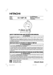
Cut-Off Machine
Tronzadora
CC 16SB
Read through carefully and understand these instructions before use.
Leer cuidadosamente y comprender estas instrucciones antes del uso.
Handling instructions
Instrucciones de manejo
001Cover_CC16SB_Eng_Spa
3
1/30/09, 9:56
1
2
1
4
5
3
2
4
3
6
8
5
6
6
9
7
0
7
9
0
7
B
C
A
8
9
E
F
D
G
1
00Table_CC16SB_Eng_Spa
1
1/30/09, 9:57
English
1
2
3
Power cord
Switch
Grounding terminal
4
Power supply cord
5
6
7
Grounding wire
Direction of A
Direction of B
When setting at an
angle of 90°
When setting at an
angle of 60°
When setting at an
angle of 45°
Stationary vise-jaw
M16 bolt
M8 bolt
M10 nut
Nylon clip
Shaft
Leg
8
9
0
A
B
C
D
E
F
G
Español
Cable de alimentación
Interruptor
Terminal a tierra
Cable de suministro
eléctrico
Cable de puesta a tierra
Dirección de A
Dirección de B
Al ajustar a un ángulo
de 90°
Al ajustar a un ángulo
de 60°
Al ajustar a un ángulo
de 45°
Mordaza de tornillo fija
Perno M16
Perno M8
Tuerca M10
Clip de nylon
Eje
Pata
2
00Table_CC16SB_Eng_Spa
2
1/30/09, 9:57
English
GENERAL OPERATIONAL PRECAUTIONS
WARNING! When using electric tools, basic safety
precautions should always be followed to reduce the
risk of fire, electric shock and personal injury, including
the following.
Read all these instructions before operating this product
and save these instructions.
For safe operations:
1. Keep work area clean. Cluttered areas and benches
invite injuries.
2. Consider work area environment. Do not expose
power tools to rain. Do not use power tools in
damp or wet locations. Keep work area well lit.
Do not use power tools where there is risk to
cause fire or explosion.
3. Guard against electric shock. Avoid body contact
with earthed or grounded surfaces. (e.g. pipes,
radiators, ranges, refrigerators).
4. Keep children away. Do not let visitors touch the
tool or extension cord. All visitors should be kept
away from work area.
5. Store idle tools. When not in use, tools should
be stored in a dry, high or locked up place, out
of reach of children.
6. Do not force the tool. It will do the job better and
safer at the rate for which it was intended.
7. Use the right tool. Do not force small tools or
attachments to do the job of a heavy duty tool.
Do not use tools for purposes not intended; for
example, do not use circular saw to cut tree limbs
or logs.
8. Dress properly. Do not wear loose clothing or
jewellery, they can be caught in moving parts.
Rubber gloves and non-skid footwear are
recommended when working outdoors. Wear
protecting hair covering to contain long hair.
9. Always use eye and ear protection. Other personal
protective equipment such as dust mask, gloves,
helmet and apron should be worn when necessary.
When assessing the need for a face or dust mask
consideration should be given to the harmful
properties of both the material being grounded
or coated. If in doubt, wear the protective
equipment.
10. Connect dust extraction equipment.
If devices are provided for the connection of dust
extraction and collection facilities ensure these are
connected and properly used.
11. Do not abuse the cord. Never carry the tool by
the cord or yank it to disconnect it from the
receptacle. Keep the cord away from heat, oil and
sharp edges.
12. Secure work. Use clamps or a vise to hold the
work. It is safer than using your hand and it frees
both hands to operate tool.
13. Do not overreach. Keep proper footing and balance
at all times.
14. Maintain tools with care. Keep cutting tools sharp
and clean for better and safer performance. Follow
instructions for lubrication and changing
accessories. Inspect tool cords periodically and if
damaged, have it repaired by authorized service
center. Inspect extension cords periodically and
replace, if damaged. Keep handles dry, clean, and
free from oil and grease.
15.
16.
17.
18.
19.
20.
21.
22.
Disconnect tools. When not in use, before servicing,
and when changing accessories such as blades,
bits and cutters.
Remove adjusting keys and wrenches. Form the
habit of checking to see that keys and adjusting
wrenches are removed from the tool before turning
it on.
Avoid unintentional starting. Do not carry a
plugged-in tool with a finger on the switch. Ensure
switch is off when plugging in.
Use outdoor extension leads. When tool is used
outdoors, use only extension cords intended for
outdoor use.
Stay alert. Watch what you are doing. Use common
sense. Do not operate tool when you are tired.
Check damaged parts. Before further use of the
tool, a guard or other part that is damaged should
be carefully checked to determine that it will
operate properly and perform its intended function.
Check for alignment of moving parts, free running
of moving parts, breakage of parts, mounting and
any other conditions that may affect its operation.
A guard or other part that is damaged should be
properly repaired or replaced by an authorized
service center unless otherwise indicated in this
handling instructions. Have defective switches
replaced by an authorized service center. Do not
use the tool if the switch does not turn it on and
off.
Warning
The use of any accessory or attachment, other
than those recommended in this handling
instructions, may present a risk of personal injury.
Have your tool repaired by a qualified person.
This electric tool is in accordance with the relevant
safety requirements. Repairs should only be carried
out by qualified persons using original spare parts.
Otherwise this may result in considerable danger
to the user.
PRECAUTIONS ON USING CUT-OFF
MACHINE
1.
2.
3.
4.
5.
6.
7.
8.
9.
10.
11.
12.
13.
14.
Always apply a trial run.
Handle the cut-off wheel with care.
Start cutting only after motor revolutions reach
full speed.
Promptly cut OFF the switch when abnormality
observed.
Use the normal cut-off wheel on its normal working
surface.
Guard against cut-off sparks.
Properly replace the cut-off wheel.
A revolving cut-off wheel should never be touched.
Pay attention to cut-off wheel preservation.
Handle cut-off wheel clamping parts with care.
Keep hands out of the line of cut-off wheel.
Do not perform any operation freehand.
Never reach around or behind cut-off wheel.
Shut off power and wait for cut-off wheel to stop
before servicing and adjusting tool.
3
01Eng_CC16SB_Eng_Spa
3
1/30/09, 9:57
English
SPECIFICATIONS
Item
Motor
Motor Output
2.2 KW
3.7 KW
Type
Three phase induction motor
Power source
Three phase alternating current 50/60Hz
Voltage (V)
200
220
230
240
/
/
/
/
Full-load current 2.2KW 9.9/8.9 8.5/8.0
(50/60Hz)
3.7KW 15.8/14.5 13/12.5
Cut-off
Type
wheel
Dimensions
380
8.0/—
7.9/7.2
415
440
4.8/—
—/4.3
8.0/—
—/6.8
Reinforced resinoid cut-off wheel
Outer diameter 405 × thickness 2.8 × arbor hole diameter 25.4 mm
Maximum working
peripheral speed
3800 m/min
No-load speed
2290/2730/min (50/60Hz)
No-load peripheral
speed
2430/2900/min (50/60Hz)
2910/3470 m/min (50/60Hz)
Distance from wheel lower
side to base top
170 mm
Dimensions of base top
583 x 370 mm
Maximum opening of vise
230 mm
Height of machine
965 mm
Weight
86 kg
V-belt size
96 kg
Type 3V-375·············2
ACCESSORIES
Standard accessories
400
4.9/4.6 4.8/4.4
Cut-off wheel ················· 1
Spanner ·························· 1
Special accessories
Modification set for 3.7KW 51-P motor
(available on separate order)
APPLICATION
Cutting off the following materials:
䡬 Round bars
䡬 Pipes
䡬 Various types of shaped steel
䡬 Aluminum alloy (use a chip saw)
PRIOR TO OPERATION
4. Grounding the Equipment. (Fig. 2)
Prior to shipping, the equipment is subjected to a
rigid factory inspection to prevent electric shocks
during operation. Further, the equipment is provided
with a means of grounding as a safety precaution.
Wind the grounding wire round the power supply
cord not to contact with rotating portion.
5. Pull out the handle
The handle is pressed against the motor for shipping
purpose. Therefore, pull out the handle to the
position that offers the best operating comfort and
secure it in position with two cross-head screws.
6. Removing anticorrosive coating
Ascertain that anticorrosive coating on the base
surfaces is thoroughly removed with a cloth wellmoistened with gasoline.
CONFIRM BEFORE USE
Exercise care in the following procedures before
connecting the cord to power source.
1. Installation
This is a portable tool with wheels. Install it on a
level site and prevent it from sliding by securing
each wheel with a wedge or a similar peg.
2. Connecting the power cord to the machine body
Open the push-button switch and connect the power
cord to the connection terminal. (see Fig. 1)
Use a cabtyre cord with 2 mm2 or more core wire
for the power cord.
3. Clamping the power cord
Use the nylon clip provided for the machine body
to clamp the power cord. (see Fig. 8)
CAUTION
Before plugging the power cord in a receptacle,
ascertain the following points:
1. Ascertain cut-off wheel condition
Ascertain that all cut-off wheels are in perfect
condition, and do not display scars or cracks.
2. Ascertain clamping of the cut-off wheel
Although they have been fully clamped at the factory
prior to delivery, re-clamp the clamping nuts securely
for safety. (See the item on Replacing the cut–off
Wheel).
4
01Eng_CC16SB_Eng_Spa
4
1/30/09, 9:57
English
CAUTION
When the clamping nuts are loosened, the cut-off
wheel may be damaged when the wheel axle starts
revolving, creating a hazardous condition.
3. Ascertain clamping of the protective cover
Possible accidents such as a cracked cut-off wheel
are prevented by this protective cover (guard cover).
Although it has been fully clamped at the factory
prior to delivery, securely re-clamp the mounting
screws for safety.
CAUTION
Confirm that the protective cover (wheel cover) is
securely mounted.
4. Confirming belt tension
Ascertain that belt tension is appropriate.
CAUTION
Excessive tension will damage the motor and
insufficient tension will cause the belt to slip; in
both instances, the machine will be unable to fully
demonstrate its performance.
5. Ascertain the working power supply
Always use the machine under the power supply
specified on the instruction plate.
6. Ascertain that the switch is OFF
Should the cord be carelessly or inadvertently
plugged in a receptacle when the switch is ON,
unexpected and serious trouble may occur.
Then plug the cord into a receptacle and ascertain the
following:
1. Check the Rotative Direction
The rotating direction can be determined by referring
to the arrow direction on the safety-cover.
2. Inspect facial deflection of the Cut-off wheel
Rotate the Cut-off wheel to inspect any facial
deflection.
A heavy deflection will cause the Cut-off wheel to
shift.
3. Applying a trial run
Continued grinding without noticing a cracked or
split cut-off wheel may prove to be very hazardous.
Before starting operation, temporarily step away
from the front position and make a trial run to
confirm that no abnormalities are involved.
Trial run periods:
When replacing a cut-off wheel ...... Over 3 minutes.
When starting routine work ............ Over 1 minute.
MOUNTING AND DISMOUNTING
CAUTION
Always turn OFF the switch before starting the
dismounting procedure.
1. Dismounting the Cut-off Wheel (Fig. 3)
(1) As shown in Fig. 3, the spindle has a rotation stop
hole. Stop the spindle by inserting a screwdriver
(or a 10 mm rod) through the hole.
(2) Remove the sub-cover and use the provided
19×24 mm spanner to loosen the M16 bolt.
(3) Remove the M16 bolt, 16 mm spring washer, washer,
and wheel washer; then dismount the wheel.
2. Mounting the Cut-off Wheel
(1) Thoroughly remove dust from the wheel washer,
washer, 16 mm spring washer, and M16 bolt, then
mount the wheel by following the dismounting
procedure in reverse order. Always install the washers.
(2) After clamping the 16 mm clamping bolt is
completed, always mount the sub-cover.
CUTTING PROCEDURES
CAUTION
It is dangerous to remove or install the workpiece
while the cut-off wheel turning.
(1) Grip the cutting material steady with a vise. Should
gripping be insufficient, it will lead to the cutting
material jumping off, and even to a hazard of
cracking the cut-off wheel.
(2) Rotate the cut-off wheel, gently press down the
handle, and bring the cut-off wheel close to the
cutting material.
(3) When the cut-off wheel contacts the cutting material,
gently press down the handle further and start cutting.
(4) When cutting (or designated slotting) is completed,
raise the handle and restore it to its original position.
(5) At the termination of each cutting process, turn OFF
the switch to stop rotation and proceed with the
subsequent cutting job.
HOW TO OPERATE
1. Cutting at angles (Fig. 4 and 5)
(1) The machine permits cutting at angles of 45° or 60°.
(2) Loosen the two bolts on the stationary vise-jaw,
then set the working surface on the vice-jaw at any
angles of 90°, 60°, or 45° as shown in Fig. 5. Upon
completion of setting, securely tighten the two bolts.
2. Moving the stationary vise-jaw (Fig. 6)
The vise opening is set at the maximum of 180 mm
when shipped from the factory. In case an opening
of more than 180 mm is required, after unscrewing
the two bolts, move the vise-jaw to the position
shown by the dotted line.
In this case, the maximum vise opening will become
230 mm.
MAINTENANCE AND INSPECTION
CAUTION
Be sure to switch off and pull off the plug from
the power outlet before inspection and maintenance.
1. Replacing a cut-off wheel
When the cut-off wheel has already become dull
while continually using, the unnecessary load is got
from the motor. Consequently, redress or replace
a dull cut-off wheel to ensure grinding efficiency.
2. Inspecting the mounting screws
Regularly inspect all mounting screws and ensure
that they are properly tightened. Should any of the
screws be loose, retighten them immediately. Failure
to do so could result in serious hazard.
3. The Cut-off Machine promptly starts rotating and
cutting when the switch is turned ON. Although this
design is convenient, it will create hazards if handled
erroneously.
Always disconnect the power cord from the line
receptacle after use. After completing each cutting
job, store the machine in a dry location beyond the
reach of children.
5
01Eng_CC16SB_Eng_Spa
5
1/30/09, 9:57
English
4. Periodically inspect every part of this Cut-off Machine
as to whether or not loosening has occurred.
Retighten any loosened parts.
When using the Cut-off Machine without retightening
loose parts, a hazard may result.
5. Changing Belts
(1) Remove two M8 bolt screws used to secure the belt
cover shown in Fig. 7.
(2) By loosening four M10 nuts shown in Fig. 7 on the
belt side shown in Fig. 8, push the motor to the
front, removing the belt. When attaching the belt,
follow reverse procedures to the above.
6. Stretching the belt (Fig. 8)
Stretch the belt to form a straight tension.
When stretching is completed, clamp the belt with
10 mm nuts (4 pcs.).
7. Oiling
Apply oil to the slideway of the leg and shaft
approximately once a month to ensure smooth
shaft rotation. (Fig. 9)
(Machine oil is suitable.)
8. Cleaning
Occasionally use a cloth to wipe off chips and dust
from the machine body.
9. Service parts list
CAUTION
Repair, modification and inspection of Hitachi Power
Tools must be carried out by an Hitachi Authorized
Service Center.
This Parts List will be helpful if presented with the
tool to the Hitachi Authorized Service Center when
requesting repair or other maintenance.
In the operation and maintenance of power tools,
the safety regulations and standards prescribed in
each country must be observed.
MODIFICATIONS
Hitachi Power Tools are constantly being improved
and modified to incorporate the latest technological
advancements.
Accordingly, some parts may be changed without
prior notice.
NOTE:
Due to HITACHI’s continuing program of research and
development, the specifications herein are subject to
change without prior notice.
6
01Eng_CC16SB_Eng_Spa
6
1/30/09, 9:57
Español
PRECAUCIONES GENERALES PARA LA
OPERACIÓN
¡ADVERTENCIA! Cuando utilice herramientas eléctricas,
tome las medidas de seguridad básicas para reducir el
riesgo de incendios, descargas eléctricas, y lesiones,
incluyendo lo siguiente. Lea todas estas instrucciones
antes de utilizar este producto y guárdelas.
Para realizar operaciones seguras:
1. Mantener el área de trabajo limpia, áreas y bancos
de trabajo desordenados son causa de daños
personales.
2. Considerar el medio ambiente del área de trabajo.
No exponer las herramientas eléctricas a la lluvia.
No usar herramientas eléctricas en lugares mojados o húmedos. Mantener el área de trabajo bien
iluminada.
No utilice herramientas eléctricas cuando exista
el riesgo de incendios o de explosión.
3. Protegerse contra descargas eléctricas. Evitar el
contacto del cuerpo con las superficies puestas
a tierra. (p. ej., tubos, radiadores, hornos de
microondas, o refrigeradores.)
4. Mantener a los niños alejados. No dejar que los
visitantes toquen las herramientas ni los cables
de extensión. Todos los visitantes deberán
mantenerse alejados del área de trabajo.
5. Guardar las herramientas que no se usen y
ponerlos en lugares secos, altos o cerrados, fuera
del alcance de los niños.
6. No forzar las herramientas, éstas trabajarán más
y con mayor seguridad cuando cumplan con las
especificaciones para las cuales fueron diseñadas.
7. Usar las herramientas apropiadas. No forzar
pequeñas herramientas o accesorios a realizar el
trabajo de herramientas de mayor potencia. No
utilizar herramientas para otros propósitos para
los cuales no fueron diseñadas, por ejemplo, no
utilizar sierras circulares para cortar ramas de
árboles o troncos.
8. Vestir apropiadamente. No ponerse ropas que
queden flojas ni tampoco joyas. Estas podrian
quedar atrapadas en las partes móviles de las
herramientas. Cuando se trabaje en exteriores, se
recomienda el uso de guantes de goma y calzado
que no resbale.
9. Utilizar siempre equipos de protección para los
ojos y los oídos. Siempre que sea necesario,
utilizar asimismo otros equipos de protección
personal tales como mascarilla contra el polvo,
guantes, casco duro y delantal. Cuando considere
la necesidad de utilizar una máscara facial o una
mascarilla contra el polvo, se deberá tener en
cuenta las propiedades nocivas tanto del material
rectificado como revestido. En caso de dudas,
utilizar el equipo de protección.
10. Conecte un equipo colector de polvo.
Si existen dispositivos para la conexión de equipos
de extracción y recolección de polvo, cerciórese
de que éstos estén conectados adecuadamente,
y de utilizarlos en la forma correcta.
11. Cuidar del cable. Nunca lleve las herramientas
colgando del cable, tampoco tire del cable para
efectuar la desconexión de las herramientas.
Mantener el cable alejado del calor, aceite y bordes
agudos.
7
02Spa_CC16SB_Eng_Spa
7
12.
13.
14.
15.
16.
17.
18.
19.
20.
21.
22.
Asegurar la pieza de trabajo usando para ello
abrazaderas o un tornillo. Esto es más seguro que
usar las manos, además, ambas manos quedan
libres para operar la herramienta.
No extenderse excesivamente para efectuar un
trabajo. Mantener en todo momento un buen
balance y base de apoyo.
Mantener cuidadosamente las herramientas.
Tenerlas siempre limpias y afiladas para obtener
un mejor rendimiento y un funcionamiento más
seguro. Seguir siempre las instrucciones para la
lubricación y el cambio de accesorios. Inspeccionar
periódicamente los cables de las herramientas y
si estuviesen danãdos, hacer que los reparen
técnicos o expertos. Inspeccionar periódicamente
los cables de extensión y cambiarlos si estuviesen
dañados. Mantener los mangos secos, limpios, y
libres de aceite y grasa.
Desconectar las herramientas cuando no se usen,
antes de repararlas, y cuando se cambien
accesorios como por ejemplo, cuchillas, brocas,
cortadores, etc.
Quitar las cuñas y las llaves de tuercas.
Acostumbrarse a comprobar si se han quitado las
cuñas y las llaves de tuercas antes de poner las
herramientas en funcionamiento.
Evitar puestas en funcionamiento sin fin alguno.
No llevar las herramientas con los dedos en los
inerruptores mientras que éstas están conectadas.
Cuando se conecten las herramientas, cerciorarse
de que los interruptores estén en la posición de
desconectados.
Para usos en exteriores usar cables de extensión.
Cuando las herramientas vayan a ser usadas en
exteriores, usar solamente cables de extensión
diseñados para tal propósito.
Estar siempre alerta y poner atención a lo que
se está haciendo, usar el sentido común y no
operar con la herramienta cuando se esté cansado.
Comprobar las piezas dañadas. Antes de seguir
con el funcionamiento de las herramientas, las
piezas que estén dañadas deberán comprobarse
cuidadosamente para determinar si pueden
funcionar apropiadamente y cumplir con la función
para las que fueron diseñadas. Comprobar el
alineamiento y agarrotamiento de piezas móviles,
rotura de piezas, montura, y cualquier otra
anomalía que pudiese afectar al rendimiento de
la herramienta. Cualquier pieza que estuviese
dañada deberá repararse apropiadamente o
cambiarse en un centro de reparaciones autorizado,
al menos que se indique, lo contrario en este
manual de instrucciones. Procurar que los
interruptores defectuosos los cambie un centro de
reparaciones autorizado.
No usar las herramientas si sus interruptores no
funcionasen apropiadamente.
Advertencia
La utilización de cualquier accesorio o aditivo no
recomendado en este manual de instrucciones
puede conducir al riesgo de lesiones.
En caso de avería, haga que su herramienta sea
reparada por un técnico cualificado.
Esta herramienta eléctrica está de acuerdo con los
requisitos de seguridad pertinentes. Las
reparaciones solamente deberán realizarlas
1/30/09, 9:57
Español
7.
técnicos cualificados utilizando piezas de repuesto
originales. De lo contrario, el usuario podría
lesionarse.
8.
9.
PRECAUCIONES SOBRE EL USO DE LA
TRONZADORA
1.
2.
3.
4.
5.
6.
10.
Realice siempre una prueba.
Maneje la rueda cortadora con cuidado.
Comience cortando sólo cuando las revoluciones
del motor alcancen plena velocidad.
Cuando observe una anomalía, desconecte el
interruptor.
Utilizar la rueda cortadora normal con su superficie
de trabajo normal.
Portegerse de las chispas.
11.
12.
13.
14.
Reemplazar la rueda cortadora cuando sea
necesario.
No debe tocar una rueda cortadora que esté
girando.
Preste atención a la conservación de la rueda
cortadora.
Maneje las piezas de agarre de la rueda cortadora
con cuidado.
Mantenga las manos alejadas de la línea de la
rueda cortadora.
No realice ninguna operación sin manos.
No se aproxime nunca alrededor o por detrás de
la rueda de corte.
Apague la alimentación y espere a que la rueda
de corte se detenga antes de hacer un
mantenimiento o ajustar la herramienta.
ESPECIFICACIONES
Salida del motor
Item
Motor
2,2 KW
Tipo
Fuente eléctrica
Tensión (V)
Corriente alterna trifásica 50/60Hz
200
220
Corriente a plena 2,2KW 9,9/8,9 8,5/8,0
carga (50/60Hz)
3,7KW 15,8/14,5 13/12,5
Rueda Tipo
cortadora
Dimensiones
3,7 KW
Motor de inducción trifásico
230
240
/
/
/
/
400
8,0/—
7,9/7,2
415
440
4,8/—
—/4,3
8.0/—
—/6,8
Rueda cortadora resinoide reforzada
Diámetro externo 405 × grosor 2,8 × diámetro de orificio de pérgola 25,4 mm
Velocidad periférica
de trabajo máxima
Velocidad sin carga
380
4,9/4,6 4,8/4,4
3800 m/min
2290/2730/min (50/60Hz)
Velocidad periférica
sin carga
2430/2900/min (50/60Hz)
2910/3470 m/min (50/60Hz)
Distancia desde el lateral
inferior de la rueda hasta la
parte superior de la base
170 mm
Dimensiones de la parte
superior de la base
583 x 370 mm
Apertura máxima del tornillo
230 mm
Altura de la máquina
965 mm
Peso
86 kg
Tamaño de correa en V
96 kg
Tipo 3V-375·············2
*Verificar indefectiblemente los datos de la placa de características de la máquina, pues varían de acuerdo
al país de destino.
APLICACION
ACCESORIOS
Accesorios estándares
Rueda cortadora ............ 1
Llave inglesa .................. 1
Accesorios especiales
(disponible por solicitud)
Conjunto de modificación para motor
3,7KW 51-P
Corte de los siguientes materiales:
䡬 Barras redondas
䡬 Tubos
䡬 Varios tipos de acero con forma
䡬 Aleación de aluminio (utilización de sierra)
8
02Spa_CC16SB_Eng_Spa
8
1/30/09, 9:57
Español
ANTES DE LA PUESTA EN MARCHA
Preste atención en los siguientes procedimientos antes
de conectar el cable a la fuente eléctrica.
1. Instalación
Se trata de una herramienta portátil con ruedas.
Instálela en un lugar nivelado y evite que se deslice
fijando cada rueda con una cuña o una clavija
similar.
2. Conecte el cable de alimentación al cuerpo de la
máquina
Abra el interruptor de botón y conecte el cable de
alimentación al terminal de conexión. (consulte la
Fig. 1)
Utilice un cable multifilar con hilo de 2 mm2 o más
para el cable de alimentación.
3. Sujeción del cable de alimentación
Utilice el clip de nylon proporcionado para el cuerpo
de la máquina para sujetar el cable de alimentación.
(véase Fig. 8)
4. Conexión a tierra del equipo. (Fig. 2)
Antes del envío, el equipo se somete a una rigurosa
inspección de fábrica para evitar descargas eléctricas
durante el funcionamiento. Asimismo, el equipo se
proporciona con un medio de conexión a tierra
como precaución de seguridad.
Enrolle el cable de tierra alrededor del cable de
suministro eléctrico para que no contacte la parte
giratoria.
5. Tirar del manillar
El manillar se presiona contra el motor para fines
de envío. Por lo tanto, tire del manillar a la posición
que ofrezca la mayor comodidad operativa y fíjela
en la posición con dos tornillos de estrella.
6. Retirar el revestimiento anticorrosivo
Observe que el revestimiento anticorrosivo en las
superficies de la base se retira completamente con
un trapo bien impregnado con gasolina.
CONFIRMAR ANTES DE UTILIZAR
PRECAUCION
Antes de enchufar el cable de alimentación en un
receptáculo, observe los siguientes puntos:
1. Determine el estado de la rueda cortadora
Observe que todas las ruedas cortadoras están en
perfecto estado y no muestran cicatrices o grietas.
2. Determine la sujeción de la rueda cortadora
Aunque se han apretado completamente en la fábrica
antes de la entrega, vuelva a apretar la tuerca de
sujeción por motivos de seguridad. (Consulte el
item en Sustituir la rueda cortadora).
PRECAUCION
Cuando las tuercas de sujeción están aflojadas, la
rueda cortadora puede dañarse cuando el eje de
la rueda comienza a girar, creando una situación
de peligro.
3. Determinar la sujeción de la cubierta protectora
Con esta cubierta protectora (cubierta de protección)
se evitan accidentes como el agrietamiento de la
rueda cortadora.
Aunque se ha apretado completamente en fábrica
antes de su entrega, vuelva a apretar los tornillos
de instalación bien para su seguridad.
PRECAUCION
Confirme que la cubierta protectora (cubierta de la
rueda) está bien instalada.
4. Confirmar la tensión de la correa
Determinar que la tensión de la correa es adecuada.
PRECAUCION
Una tensión excesiva dañará el motor y una tensión
insuficiente hará que la correa se deslice; en ambos
casos, la máquina no podrá demostrar
completamente su rendimiento.
5. Determinar el suministro eléctrico de trabajo
Utilice siempre la máquina con el suministro eléctrico
especificado en la placa de instrucciones.
6. Determinar que el interruptor está apagado (OFF)
Si el cable se enchufa sin cuidado y sin querer en
un receptáculo cuando el interruptor está encendido
(ON), pueden producirse problemas inesperados y
graves.
A continuación, enchufe el cable en un receptáculo y
observe lo siguiente:
1. Compruebe la dirección de giro
La dirección de giro puede determinarse consultando
la dirección de la flecha en la cubierta de seguridad.
2. Inspeccione la desviación facial de la rueda cortadora
Gire la rueda cortadora para inspeccionar la
desviación facial.
Una desviación fuerte hará que la rueda cortadora
se displace.
3. Realice una prueba
Seguir moliendo sin observar una rueda agrietada
o rota podría ser muy peligroso.
Antes de comenzar la operación, aléjese
temporalmente de la posición frontal y realice una
prueba para confirmar que no existe ninguna
anomalía.
Periodos de prueba:
Al sustituir una rueda cortadora
..................................................... Más de 3 minutos.
Al comenzar trabajo rutinario
..................................................... Más de 1 minuto.
MONTAJE Y DESMONTAJE
PRECAUCION
Apague siempre el interruptor antes de comenzar
el procedimiento de desmontaje
1. Desmontaje de la rueda cortadora (Fig. 3)
(1) Tal y como se muestra en la Fig. 3, el eje tiene
un orificio de parada de giro. Detenga el eje
introduciendo un destornillador (o una varilla de 10
mm) a través del orificio.
(2) Retire la subcubierta y utilice la llave inglesa de
19 x 24 mm proporcionada para aflojar el perno M16.
(3) Retire el perno M16, la arandela de resorte de 16
mm, la arandela y la arandela de la rueda; a
continuación desmonte la rueda.
2. Montaje de la rueda cortadora
(1) Retire con cuidado el polvo de la arandela de la
rueda, la arandela, la arandela de resorte de 16 mm
y el perno de M16; a continuación, monte la rueda
siguiendo el procedimiento de desmontaje en orden
contrario. Instale siempre las arandelas.
(2) Tras sujetar el perno de sujeción de 16 mm, monte
la subcubierta.
9
02Spa_CC16SB_Eng_Spa
9
1/30/09, 9:57
Español
PROCEDIMIENTOS DE CORTE
PRECAUCION
Es muy peligroso extraer o instalar la pieza de
trabajo con la máquina cortadora en funcionamiento.
(1) Agarre con firmeza el material de cortado con un
tornillo. Si el agarre es insuficiente el material de
cortado saltará, pudiendo causar grietas en la rueda
cortadora.
(2) Gire la rueda cortadora presionando ligeramente el
asa, y acérquela al material que desee cortar.
(3) Cuando la rueda cortadora entre en contacto con
el material, presione ligeramente hacia abajo el asa
para iniciar el corte.
(4) Cuando finalice el corte (o el ranurado diseñado),
levante el asa y devuélvala a la posición original.
(5) Al terminar cada proceso de corte, ponga el
interruptor en OFF a fin de parar la rotación y
efectúe el trabajo de corte siguiente.
UTILIZACION
1. Corte en ángulo (Figs. 4 y 5)
(1) La máquina permite cortar en ángulos de 45° o 60°.
(2) Afloje los dos pernos en la mordaza de tornillo fija
y ajuste la superficie de trabajo en la mordaza de
tornillo a un ángulo de 90°, 60° o 45° tal y como
se muestra en la Fig. 5. Una vez realizado el ajusto,
apriete bien los dos pernos.
2. Movimiento de la mordaza estacionaria del tornillo
de banco (Fig. 6)
La apertura de tornillo está ajustada a un máximo
de 180 mm cuando se envía de la fábrica. Si se
requiere una apertura superior a 180 mm, tras
destornillar los dos pernos, mueva la mordaza de
tornillo a la posición mostrada por la línea de
puntos.
En este caso, la apertura máxima del tornillo es de
230 mm.
MANTENIMIENTO E INSPECCION
PRECAUCION
Antes de inspeccionar la máquina cortadora y
efectuar su mantenimiento, asegúrese de poner el
interruptor en OFF y desconectar el enchufe del
cable de alimentación de la toma de la red.
1. Reemplazo de la rueda cortadora
Cuando se utilice continuamente una rueda cortadora
sin filo, el motor recibirá una carga innecesaria.
Consecuentemente, rectifique o reemplace dicha
rueda para asegurar la máxima eficacia de corte.
2. Inspeccionar los tornillos de montaje
Regularmente inspeccionar todos los tornillos de
montaje y asegurarse de que estén apretados
firmemente. Si cualquier tornillo estuviera suelto,
volver a apretarlo inmediatamente. El no hacer esto
provocaría un riesgo serio.
3. La máquina de corte comienza a girar y a cortar
inmediatamente cuando el interruptor se gira a ON
(encendido). Aunque este diseño es práctico, se
producirán riesgos si se manipula erróneamente.
Desconecte siempre el cable eléctrico del receptáculo
de línea tras su utilización. Tras finalizar cada trabajo
de cortado, guarde la máquina en un lugar seco
fuera del alcance de los niños.
4. De forma periódica inspeccione cada parte de esta
máquina de corte para observar si se han aflojado.
Vuelva a apretar las partes aflojadas.
Cuando utilice la máquina de corte sin volver a
apretar las partes flojas, puede producirse un peligro.
5. Cambiar las correas
(1) Retire los dos tornillos M8 utilizados para fijar la
cubierta de la correa mostrados en la Fig. 7.
(2) Al aflojar cuatro tuercas M10 mostradas en la Fig.
7 en el lateral de la correa mostrado en la Fig. 8,
empuje el motor hacia delante, retirando la correa.
Cuando coloque la correa, siga los procedimientos
contrarios a los de arriba.
6. Estirar la correa (Fig. 8)
Estire la correa para formar una tensión recta.
Una vez realizado el estiramiento, fije la correa con
tuercas de 10 mm (4 piezas).
7. Engrasado
Aplique aceite en el lateral de la pata y del eje
aproximadamente una vez al mes para garantizar
un giro suave del eje. (Fig. 9)
(El aceite de la máquina es adecuado.)
8. Limpieza
Utilice de forma ocasional un trapo para limpiar las
astillas y el polvo del cuerpo de la máquina.
9. Lista de repuestos
PRECAUCION
La reparación, modificación e inspección de las
herramientas eléctricas Hitachi deben ser realizadas
por un Centro de Servicio Autorizado de Hitachi.
Esta lista de repuestos será de utilidad si es
presentada junto con la herramienta al Centro de
Servicio Autorizado de Hitachi, para solicitar la
reparación o cualquier otro tipo de mantenimiento.
En el manejo y el mantenimiento de las herramientas
eléctricas, se deberán observar las normas y
reglamentos vigentes en cada país.
MODIFICACIONES
Hitachi Power Tools introduce constantemente
mejoras y modificaciones para incorporar los últimos
avances tecnológicos.
Por consiguiente, algunas partes pueden ser
modificadas sin previo aviso.
OBSERVACION
Debido al programa continuo de investigación y
desarrollo de HITACHI estas especificaciones están
sujetas a cambio sin previo aviso.
10
02Spa_CC16SB_Eng_Spa
10
1/30/09, 9:57
11
03Back_CC16SB_Eng_Spa
11
1/30/09, 9:57
ITEM
NO.
1
2
3
4
5
6
7A
8
9
10
11
12
13
14
15
16
17
18
19
20
21
22
23
24
25
26
27
28
29
30A
31
32
33
34
35
36
37
38
39
40
41
42
43
44
45
46
47
48
49
50
51
52
53
54
55
56
57A
58
59
60
61
62
63A
64
65
66
67
68
69
70
PART NAME
Q’TY
HANDLE
GRIP
CORD ASS'Y
SPRING WASHER M6
MACHINE SCREW M6×12
TERMINAL 50051
K-TYPE SWITCH SET (SK2-TB)
MACHINE SCREW M4×8
SPRING WASHER M4
SWITCH PLATE
NUT M4
SPRING WASHER M8
BOLT M8×16
BELT COVER ARM
BELT COVER
V-BELT (3V-375)
MACHINE SCREW M6×12
SPRING WASHER M6
HEX. SOCKET SET SCREW M8×8
PULLEY (B)
BEARING COVER
BALL BEARING 6206VVCMPS2S
FEATHER KEY 7×7×35
SPINDLE
PIN D3×5.5
MACHINE SCREW M6×16
NAME PLATE
RIVET D2.5×4.8
SAFETY COVER
MARK PLATE
MACHINE SCREW M6×16
NUT M6
WHEEL WASHER (C)
CUT-OFF WHEELS 405MM
WHEEL WASHER (E) ASS'Y
WHEEL WASHER (D)
TERMINAL PLATE (A)
MACHINE SCREW M4×20
SPRING WASHER M4
NYLON CLIP
WASHER M4
MACHINE SCREW M4×16
TERMINAL COVER (A)
SPRING WASHER M5
MACHINE SCREW M5×45
CONNECTION PLATE
RIVET D2.5×4.8
BELT COVER (B)
SPRING WASHER M8
BOLT M8×16
SPRING WASHER M10
NUT M10
MOTOR COVER
NUT M4
BOLT M10×35
BOLT WASHER M10
ARM
BOLT WASHER M4
HEX. SOCKET SET SCREW M8×20
SPRING
WHEEL COVER
FELT PACKING
HITACHI LABEL
SPRING WASHER M6
MACHINE SCREW M6×16
SUB COVER
WING BOLT M6×10
BOLT WASHER M16
SPRING WASHER M16
SCREW (E)
1
1
1
2
2
3
1
2
2
1
2
4
4
1
1
2
3
3
2
1
1
2
1
1
1
2
1
4
1
1
2
4
1
1
1
1
1
1
1
2
2
2
1
2
2
1
4
1
2
2
4
4
1
2
4
6
1
1
1
1
1
1
1
3
3
1
2
1
1
1
ITEM
NO.
71
72
73
74
75
76
77
78
79
80
81
82
83
84
85
86
87
88
89
90
91
92
93
94
95
96
97
98
99
100
101
102
103
104
105
106
107
108
110
701
PART NAME
ROLL PIN D4×16
SCREW COVER
SCREW BASE
SCREW CONNECTOR
WASHER M10
BOLT M12×100
BOLT WASHER M12
VISE (A)
L-BOLT 16MM
WASHER M16
L-BOLT 16MM
BOLT WASHER M16
VISE (B)
CABLE TIE
GROMMET
CONNECTOR 50097
MOTOR (FOR THREE-PHASE)
PULLEY (A)
HEX. SOCKET SET SCREW M8×8
SCREW
BOLT M10×30
SPRING WASHER M10
BASE
RETAINING RING FOR D25 SHAFT
SHAFT (A)
LEG
LEG
BOLT M10×30
SPRING WASHER M10
SPARK SHOOT
SPLIT PIN D3×15
WASHER M10
WHEEL
SHAFT (B)
SLIDE BASE
NUT M12
MACHINE SCREW M6×12
SPRING WASHER M6
SCREW VISE ASS'Y
WRENCH 19/24MM
Q’TY
1
1
1
1
1
1
1
1
1
1
1
1
1
1
1
3
1
1
2
1
2
2
1
2
1
1
1
4
4
1
4
4
4
2
1
1
2
2
1
1
12
03Back_CC16SB_Eng_Spa
12
1/30/09, 9:57
13
03Back_CC16SB_Eng_Spa
13
1/30/09, 9:57
14
03Back_CC16SB_Eng_Spa
14
1/30/09, 9:57
Hitachi Koki Co., Ltd.
901
Code No. H99299041 N
Printed in Japan
03Back_CC16SB_Eng_Spa
15
1/30/09, 9:57