1
1
2
3
4
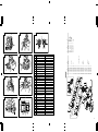
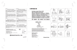
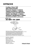
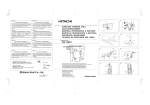
Cordless Impact Driver/Wrench
Atornillador/Llave de impacto a batería
1
1
3
2
2
4
1
WH 12DAF2 • WR 12DAF2
7
5
1
6
6
8
8
7
〈UC14YFA〉
5
B
WH12DAF2
6
9
E
0
WR12DAF2
8
C
Read through carefully and understand these instructions before use.
Leer cuidadosamente y comprender estas instrucciones antes del uso.
C
Handling instructions
Instrucciones de manejo
711
Code No. C99141441
Printed in China
D
A
7
Hitachi Koki Co., Ltd.
C
〈UC18YG〉
1
F
G
E
H I
E
1
2
3
4
Cordless Impact Driver/Wrench
Atornillador/Llave de impacto a batería
1
1
3
2
2
4
1
WH 12DAF2 • WR 12DAF2
7
5
1
6
6
8
8
7
〈UC14YFA〉
5
B
WH12DAF2
6
9
E
0
WR12DAF2
8
C
Read through carefully and understand these instructions before use.
Leer cuidadosamente y comprender estas instrucciones antes del uso.
C
Handling instructions
Instrucciones de manejo
711
Code No. C99141441
Printed in China
D
A
7
Hitachi Koki Co., Ltd.
C
〈UC18YG〉
1
F
G
E
H I
E
U
J
3
L
C
1
1
1
1
1
1
1
1
1
(B)
(A)
V
V
B
319-926
319-927
–––––––––––
–––––––––––
–––––––––––
–––––––––––
–––––––––––
324-359
322-611
2
R
"GBR"
4
17
M5
EB1214S
EB1220BL
EB1226HL
UC18YG
UC14YFA
10
5
D
9
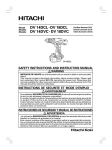
Insertar
5
Pull out
Sacar
6
Insert
Insertar
7
Pilot lamp
Lámpara piloto
8
Hole for connecting the
rechargeable battery
Agujero para conectar la batería
recargable
9
Movement
Movimiento
0
Guide sleeve
Manguito guía
A
Hexagonal hole in the anvil
14
13
Orificio hexagonal en el yunque
B
Driver bit
Punta de destornillador
C
Hexagonal socket
3
Recaptáculo hexanogal
D
Groove
M
Ranura
E
Anvil
Yunque
F
Pin
Pasador
G
Ring
Anillo
H
Hole
O
Orificio
I
Plunger
J
Embolo
J
Hook
J
16
15
N
Gancho
K
Spring
Resorte
L
Larger diameter faces away
El diámetro más grande queda en
dirección opuesta
J
M
Switch
Interruptor
N
Phillips-head screwdriver
, .
P
Destornillador con cabeza Phillips
O
Screw
Tornillo
P
Arrow
R
S
Flecha
Q
Hook cover
Cubierta del gancho
R
Indentation
Indentación
S
Protuberance
T
S
Saliente
T
N batteries
Pilas N
U
Push button
. ,
Q
R
Q
Pulsador
V
Push
Presionar
3
" 33, 34"
D2 × 6
M5
Insert
115L
60L
D4 × 20
Mango
4
6901VVCMPS2L
Enganche
Handle
D3
Latch
3
D5.556
2
C
1
4
1
1
1
1
2
1
28
1
1
1
1
1
2
2
1
1
1
1
1
1
1
1
1
7
1
1
1
1
1
1
2
1
1
1
1
1
Español
Batería recargable, 12 V
L
K
2
English
12 V Rechargeable battery
B
324-856
992-630
324-857
323-194
323-193
323-192
959-154
323-949
321-934
315-978
323-944
316-172
316-171
323-945
323-941
323-942
323-946
319-911
690-1VV
323-947
321-894
321-893
323-948
321-876
321-877
302-086
–––––––––––
324-855
321-917
321-871
–––––––––––
321-918
321-672
320-288
306-952
323-710
320-777
320-776
J
1
A
1
2
3
4
5
6
7
8
9
10
11
12
13
14
15
16
17
18
19
20
21
22
23
24
25
26
27
28
30
31
29
32
33
34
35
36
37
38
12
WR12DAF2
11
D
"3-22"
D4 × 40
A
39
40
41-1
41-2
41-3
501-1
501-2
502-1
502-2
1
24
U
J
3
L
C
1
1
1
1
1
1
1
1
1
(B)
(A)
V
V
B
319-926
319-927
–––––––––––
–––––––––––
–––––––––––
–––––––––––
–––––––––––
324-359
322-611
2
R
"GBR"
4
17
M5
EB1214S
EB1220BL
EB1226HL
UC18YG
UC14YFA
10
5
D
9
Insertar
5
Pull out
Sacar
6
Insert
Insertar
7
Pilot lamp
Lámpara piloto
8
Hole for connecting the
rechargeable battery
Agujero para conectar la batería
recargable
9
Movement
Movimiento
0
Guide sleeve
Manguito guía
A
Hexagonal hole in the anvil
14
13
Orificio hexagonal en el yunque
B
Driver bit
Punta de destornillador
C
Hexagonal socket
3
Recaptáculo hexanogal
D
Groove
M
Ranura
E
Anvil
Yunque
F
Pin
Pasador
G
Ring
Anillo
H
Hole
O
Orificio
I
Plunger
J
Embolo
J
Hook
J
16
15
N
Gancho
K
Spring
Resorte
L
Larger diameter faces away
El diámetro más grande queda en
dirección opuesta
J
M
Switch
Interruptor
N
Phillips-head screwdriver
, .
P
Destornillador con cabeza Phillips
O
Screw
Tornillo
P
Arrow
R
S
Flecha
Q
Hook cover
Cubierta del gancho
R
Indentation
Indentación
S
Protuberance
T
S
Saliente
T
N batteries
Pilas N
U
Push button
. ,
Q
R
Q
Pulsador
V
Push
Presionar
3
" 33, 34"
D2 × 6
M5
Insert
115L
60L
D4 × 20
Mango
4
6901VVCMPS2L
Enganche
Handle
D3
Latch
3
D5.556
2
C
1
4
1
1
1
1
2
1
28
1
1
1
1
1
2
2
1
1
1
1
1
1
1
1
1
7
1
1
1
1
1
1
2
1
1
1
1
1
Español
Batería recargable, 12 V
L
K
2
English
12 V Rechargeable battery
B
324-856
992-630
324-857
323-194
323-193
323-192
959-154
323-949
321-934
315-978
323-944
316-172
316-171
323-945
323-941
323-942
323-946
319-911
690-1VV
323-947
321-894
321-893
323-948
321-876
321-877
302-086
–––––––––––
324-855
321-917
321-871
–––––––––––
321-918
321-672
320-288
306-952
323-710
320-777
320-776
J
1
A
1
2
3
4
5
6
7
8
9
10
11
12
13
14
15
16
17
18
19
20
21
22
23
24
25
26
27
28
30
31
29
32
33
34
35
36
37
38
12
WR12DAF2
11
D
"3-22"
D4 × 40
A
39
40
41-1
41-2
41-3
501-1
501-2
502-1
502-2
1
24
English
GENERAL OPERATIONAL PRECAUTIONS
WARNING! When using battery operated tools, basic
safety precautions should always be followed to reduce
the risk of fire, leaking batteries and personal injury,
including the following.
Read all these instructions before operating this product
and save these instructions.
For safe operations:
1.
Keep work area clean. Cluttered areas and benches
invite injuries.
2.
Consider work area environment. Do not expose
tools to rain. Do not use tools in damp or wet
locations. Keep work area well lit.
Do not use tools where there is risk to cause fire
or explosion.
3.
Keep children away. Do not let visitors touch the
tool. All visitors should be kept away from work
area.
4.
Store batteries or idle tools. When not in use,
tools and batteries should be stored separately in
a dry, high or locked up place, out of reach of
children.
Ensure that battery terminals cannot be shorted
by other metal parts such as screws nails etc.
5.
Do not force the tool. It will do the job better and
safer at the rate for which it was intended.
6.
Use the right tool. Do not force small tools or
attachments to do the job of a heavy duty tool.
Do not use tools for purposes not intended.
7.
Dress properly. Do not wear loose clothing or
jewellery, they can be caught in moving parts.
Rubber gloves and non-skid footwear are
recommended when working outdoors. Wear
protecting hair covering to contain long hair.
8.
Use safety glasses. Also use face or dust mask
if the cutting operation is dusty.
9.
Connect dust extraction equipment.
If devices are provided for the connection of dust
extraction and collection facilities, ensure these
are connected and properly used.
10. Do not abuse the cord (if fitted). Never carry the
tool by the cord or yank it to disconnect it from
the socket. Keep the cord away from heat, oil and
sharp edges.
11. Secure work. Use clamps or a vice to hold the
work. It is safer than using your hand and it frees
both hands to operate the tool.
12. Do not overreach. Keep proper footing and balance
at all times.
13. Maintain tools with care. Keep cutting tools sharp
and clean for better and safer performance. Follow
instructions for lubrication and changing
accessories. Inspect tool cords periodically and if
damaged, have it repaired by authorized service
facility. Keep handles dry, clean, and free from oil
and grease.
14. Disconnect tools. Where the designs permits,
disconnect the tool from its battery pack, when
not in use, before servicing, and when changing
accessories such as blades, bits and cutters.
15. Remove adjusting keys and wrenches. Form the
habit of checking to see that keys and adjusting
wrenches are removed from the tool before turning
it on.
16. Avoid unintentional starting. Do not carry the tool
with a finger on the switch.
17. Stay alert. Watch what you are doing. Use common
sense. Do not operate the tool when you are tired.
18. Check damaged parts. Before further use of the
tool, a guard or other part that is damaged should
be carefully checked to determine that it will
operate properly and perform its intended function.
19.
䡬
䡬
䡬
䡬
20.
21.
22.
Check for alignment of moving parts, free running
of moving parts, breakage of parts, mounting and
any other conditions that may affect its operation.
A guard or other part that is damaged should be
properly repaired or replaced by an authorized
service center unless otherwise indicated in this
handling instructions. Have defective switches
replaced by an authorized service facility. Do not
use the tool if the switch does not turn it on and
off.
Warning
The use of any accessory or attachment, other
than those recommended in this handling instructions, may present a risk of personal injury.
Ensure that the battery pack is correct for the tool.
Ensure that the outside surface of battery pack or
tool is clean and dry before plugging into charger.
Ensure that batteries are charged using the correct
charger recommended by the manufacturer. Incorrect use may result in a risk of electric shock,
overheating or leakage of corrosive liquid from
the battery.
Have your tool repaired by a qualified person.
This tool is in accordance with the relevant safety
requirements. Repairs should only be carried out
by qualified persons using original spare parts,
otherwise this may result in considerable danger
to the user.
Disposal of battery
Ensure battery is disposed of safely as instructed
by the manufacturer.
If under abusive conditions, liquid is ejected from
the battery, avoid contact
If this accidentally occurs, flush with water. If
liquid contacts eyes additionally, seek medical
help.
PRECAUTIONS FOR CORDLESS IMPACT
DRIVER
1.
2.
3.
4.
5.
6.
7.
8.
9.
10.
11.
This is portable tool for tightening and loosening
screws. Use it only for these operation.
Use the earplugs if using for a long time.
One-hand operation is extremely dangerous; hold
the unit firmly with both hands when operating.
After installing the driver bit, pull lightly out the
bit to make sure that it does not come loose. If
the bit is not installed properly, it can come loose
during use, which can be dangerous.
Use the bit that matches the screw.
Tightening a screw with the impact driver at an
angle to that screw can damage the head of the
screw and the proper force will not be transmitted
to the screw. Tighten with this impact driver lined
up straight with the screw.
Always charge the battery at a temperature of 0
– 40°C.
A temperature of less than 0°C will result in over
charging which is dangerous. The battery cannot
be charged at a temperature greater than 40°C.
The most suitable temperature for charging is that
of 20 – 25°C.
Do not use the charger continuously.
When one charging is completed, leave the charger
for about 15 minutes before the next charging of
battery.
Do not allow foreign matter to enter the hole for
connecting the rechargeable battery.
Never disassemble the rechargeable battery and
charger.
Never short-circuit the rechargeable battery.
Short-circuiting the battery will cause a great
electric current and overheat. It results in burn or
damage to the battery.
4
01Eng_WH12DAF2_Eng_Spa
4
9/26/07, 19:12
English
12.
13.
14.
15.
Do not dispose of the battery in fire.
If the battery burnt, it may explode.
Do not insert object into the air ventilation slots
of the charger.
Inserting metal objects or inflammables into the
charger air ventilation slots will result in electrical
shock hazard or damaged charger.
Bring the battery to the shop from which it was
purchased as soon as the post-charging battery
life becomes too short for practical use. Do not
dispose of the exhausted battery.
Using an exhausted battery will damage the
charger.
be cut or caught in the socket. Also, be careful not
to touch the socket after using continuously it for
a long time. It gets quite hot and could burn you.
Never let the impact wrench turn without a load
when using the universal joint.
If the socket turns without being connected to a load,
the universal joint causes the socket to turn wildly.
You could get hurt or the movement of the socket
could shake the impact wrench so much as to
make you drop it.
Always charge the battery at a temperature of 0
– 40°C.
A temperature of less than 0°C will result in over
charging which is dangerous. The battery cannot
be charged at a temperature greater than 40°C.
The most suitable temperature for charging is
that of 20 – 25°C.
Do not use the charger continuously.
When one charging is completed, leave the charger
for about 15 minutes before the next charging of
battery.
Do not allow foreign matter to enter the hole for
connecting the rechargeable battery.
Never disassemble the rechargeable battery and
charger.
Never short-circuit the rechargeable battery.
Short-circuiting the battery will cause a great
electric current and overheat. It results in burn
or damage to the battery.
Do not dispose of the battery in fire.
If the battery burnt, it may explode.
Do not insert object into the air ventilation slots
of the charger.
Inserting metal objects or inflammables into the
charger air ventilation slots will result in electrical
shock hazard or damaged charger.
Bring the battery to the shop from which it was
purchased as soon as the post-charging battery
life becomes too short for practical use. Do not
dispose of the exhausted battery.
Using an exhausted battery will damage the
charger.
9.
10.
PRECAUTIONS FOR CORDLESS IMPACT
WRENCH
11.
1.
2.
3.
4.
5.
6.
7.
8.
This is a portable tool for tightening and loosening
bolts and nuts. Use it only for these operation.
Use the earplugs if using for a long time.
One-hand operation is extremely dangerous; hold
the unit firmly with both hands when operating.
Check that the socket is not cracked or broken.
Broken or cracked sockets are dangerous. Check
the socket before using it.
Secure the socket with the socket pin and the ring.
If the socket pin or ring securing the socket is damaged,
the socket may come off from the impact wrench,
which is quite dangerous. Do not use socket pins
or rings that are deformed, worn out, cracked, or in
any other way damaged. Always make sure to install
the socket pin and ring in the correct position.
Check the tightening torque.
The appropriate torque for tightening a bolt
depends on the material the bolt is made of, its
dimensions, grade, etc.
Also, the tightening torque generated by this impact
wrench depends on the materials and dimensions
of the bolt, how long the impact wrench is applied
for the way in which the socket is installed, etc.
Also the torque when the battery has just been
charged and when it is about to run out are slightly
different. Use a torque wrench to check that the
bolt has been tightened with the appropriate torque.
Stop the impact wrench before switching the
direction of rotation. Always release the switch
and wait for impact wrench to stop before
switching the direction of rotation.
Never touch the turning part.
Do not allow the turning socket section to get near
your hands or any other part of your body. You could
12.
13.
14.
15.
16.
17.
18.
MODEL
WH12DAF2:with charger and case
WR12DAF2:with charger and case
SPECIFICATIONS
POWER TOOL
Model
No-load speed
Capacity
WH12DAF2
WR12DAF2
0 – 2500/min
M4 – M8 (Small screw)
M5 – M12 (Ordinary bolt)
M5 – M10 (High tension bolt)
M6 – M14 (Ordinary bolt)
M6 – M10 (High tension bolt)
Tightening torque
Maximum 130 N·m {1330 kgf·cm}
Maximum 110 N·m {1120 kgf·cm}
Tightening is M12 high tension bolt
Tightening is M12 high tension bolt
(strength grade 12.9), when fully
(strength grade 12.9), when fully
charged at 20°C temp.
charged at 20°C temp.
Tightening time: 3 sec.
Tightening time: 3 sec.
Rechargeable battery
EB1214S: Ni-Cd battery, 12 V (1.4 Ah 10 cells)
EB1220BL: Ni-Cd battery, 12 V (2.0 Ah 10 cells)
EB1226HL: Ni-MH battery, 12 V (2.6 Ah 10 cells)
Weight
1.6 kg (EB1214S Installation)
5
01Eng_WH12DAF2_Eng_Spa
5
9/26/07, 19:12
English
CHARGER
Model
Charging time
Charging voltage
Weight
UC14YFA
EB1214S: Approx. 30 min. (at 20°C)
EB1220BL: Approx. 50 min. (at 20°C)
EB1226HL: Approx. 60 min. (at 20°C)
7.2 – 14.4 V
0.6 kg
UC18YG
EB1214S: Approx. 30 min. (at 20°C)
EB1220BL: Approx. 50 min. (at 20°C)
×
7.2 – 18 V
0.3 kg
“x” Indicates that the battery pack is not compatible with that specific charger.
NOTE: The charging time may vary according to the ambient temperature and power source voltage.
STANDARD ACCESSORIES
APPLICATION
1. Charger (UC14YFA or UC18YG) ............................... 1
2. Plastic case ................................................................ 1
Standard accessories are subject to change without
notice.
〈WH12DAF2〉
䡬 Driving and removing of small screws, small bolts,
etc.
〈WR12DAF2〉
䡬 Tightening and loosening of all types of bolts and
nuts, used for securing structural items
OPTIONAL ACCESSORIES
(Sold separately)
BATTERY REMOVAL/INSTALLATION
1. Battery (EB1214S, EB1220BL, EB1226HL)
1. Battery removal
Hold the handle tightly and push the battery latch to
remove the battery. (See Fig. 1 and 2)
CAUTION:
Never short-circuit the battery.
2. Battery installation
Insert the battery while observing its polarities. (See
Fig. 2)
2. For WH12DAF2
There are two types of attachment sizes for the driver
bit and the socket. Please refer to the table below and
select the attachment size for the driver bit or socket
that is appropriate for your WH12DAF2.
Attachment size
17mm
13mm
12mm
9mm
Type-L
Type-S
Purchase location
Republic of Korea,
Taiwan, Hong Kong,
People’s Republic of
China, Republic of
Singapore
Other than above
regions.
3. For WR12DAF2
The WR12DAF2 type is a 12.7 square driver
specification. Please select the socket with the
appropriate attachment size.
Optional accessories are subject to change without notice.
CHARGING
〈UC14YFA〉
Before using the power tool, charge the battery as follows.
1. Connect the charger’s power cord to a receptacle
When the power cord is connected, the charger’s
pilot lamp will blink in red. (At 1-second intervals.)
2. Insert the battery into the charger
Insert the battery firmly, in the direction shown in
Fig. 3, until it contacts the bottom of the charger
compartment.
CAUTION:
䡬 If the battery is inserted in the reverse direction, not
only recharging will become impossible, but it may
also cause problems in the charger such as deformed
recharging terminal.
3. Charging
When inserting a battery in the charger, charging will
commence and the pilot lamp will light up
continuously in red.
When the battery becomes fully recharged, the pilot
lamp will blink in red. (At 1-second intervals.) (See
Table 1)
(1) Pilot lamp indication
The indications of the pilot lamp will be as shown in
Table 1, according to the condition of the charger or
the rechargeable battery.
6
01Eng_WH12DAF2_Eng_Spa
6
9/26/07, 19:12
English
Table 1
Indications of the lamps
Before
charging
Blinks
(RED)
While
charging
Lights
(RED)
Charging
complete
Blinks
(RED)
Charging
impossible
Flickers
(RED)
Charging
impossible
Lights
(GREEN)
Lights for 0.5 seconds. Does not light for
0.5 seconds. (off for 0.5 seconds)
Lights continuously
Lights for 0.5 seconds. Does not light for
0.5 seconds. (off for 0.5 seconds)
Lights for 0.1 seconds. Does not light for
0.1 seconds. (off for 0.1 seconds)
Table 2 Recharging ranges of batteries
Rechargeable batteries
Temperatures at
which the battery
can be recharged
EB1214S, EB1220BL
–5°C – 60°C
EB1226HL
0°C – 45°C
4. Disconnect the charger’s power cord from the receptacle
5. Hold the charger firmly and pull out the battery
NOTE:
Be sure to pull out the battery from the charger after
use, and then keep it.
Regarding electric discharge in case of new
batteries, etc.
As the internal chemical substance of new batteries
and batteries that have not been used for an extended
period is not activated, the electric discharge might
be low when using them the first and second time.This is a temporary phenomenon, and normal time
required for recharging will be restored by recharging
the batteries 2 – 3 times.
How to make the batteries perform longer
(1) Recharge the batteries before they become completely
exhausted.
When you feel that the power of the tool becomes
weaker, stop using the tool and recharge its battery.
If you continue to use the tool and exhaust the electric
current, the battery may be damaged and its life will
become shorter.
(2) Avoid recharging at high temperatures.
A rechargeable battery will be hot immediately after
use. If such a battery is recharged immediately after
use, its internal chemical substance will deteriorate,
and the battery life will be shortened. Leave the battery
and recharge it after it has cooled for a while.
7
01Eng_WH12DAF2_Eng_Spa
The battery temperature
is
high,
making
recharging impossible.
Lights continuously
(2) Regarding the temperatures of the rechargeable battery
The temperatures for rechargeable batteries are as
shown in the table below, and batteries that have
become hot should be cooled for a while before
being recharged.
7
Malfunction in the battery
or the charger.
CAUTION:
䡬 If the battery is charged while it is heated because it
has been left for a long time in a location subject to
direct sunlight or because the battery has just been
used, the pilot lamp of the charger lights up green. In
such a case, first let the battery cool, then start
charging.
䡬 When the pilot lamp flickers in red quickly (at 0.2second intervals), check for and take out any foreign
objects in the charger’s battery installation hole. If
there are no foreign objects, it is probable that the
battery or charger is malfunctioning. Take it to your
Authorized Service Center.
䡬 Since the built-in micro computer takes about 3
seconds to confirm that the battery being charged
with UC14YFA is taken out, wait for a minimum of 3
seconds before reinserting it to continue charging. If
the battery is reinserted within 3 seconds, the battery
may not be properly charged.
〈UC18YG〉
Before using the power tool, charge the battery as follows.
1. Connect the charger power cord to the receptacle
Connecting the power cord will turn on the charger.
2. Insert the battery into the charger
Insert the battery firmly while observing its direction,
until it contacts the bottom of the charger (the pilot
lamp lights up) (See Fig. 4).
CAUTION
If the pilot lamp does not light up, pull out the
power cord from the receptacle and check the
battery mounting condition.
䡬 Regarding the temperatures of the rechargeable
battery
The temperatures for rechargeable batteries are as
shown in Table 3.
Table 3 Recharging ranges of batteries
Rechargeable batteries
EB1214S, EB1220BL
Temperatures at
which the battery
can be recharged
0°C – 45°C
䡬 The pilot lamp goes off to indicate that the battery is
fully charged.
9/26/07, 19:12
English
The battery charging time becomes longer when a
temperature is low or the voltage of the power source
is too low.
When the pilot lamp does not go off even if more
than 120 minutes have elapsed after starting of the
charging, stop the charging and contact your HITACHI
AUTHORIZED SERVICE CENTER.
CAUTION
If the battery is heated due to direct sunlight, etc.,
just after operation, the charger pilot lamp may
not light up. At that time, cool the battery first,
then start charging.
3. Disconnect the charger’s power cord from the
receptacle
4. Hold the charger firmly and pull out the battery
NOTE
After charging, pull out batteries from the charger
first, and then keep the batteries properly.
Regarding electric discharge in case of new batteries,
etc.
As the internal chemical substance of new batteries
and batteries that have not been used for an extended
period is not activated, the electric discharge might
be low when using them the first and second time.
This is a temporary phenomenon, and normal time
required for recharging will be restored by recharging
the batteries 2 – 3 times.
How to make the batteries perform longer.
(1) Recharge the batteries before they become
completely exhausted.
When you feel that the power of the tool becomes
weaker, stop using the tool and recharge its battery.
If you continue to use the tool and exhaust the electric
current, the battery may be damaged and its life will
become shorter.
(2) Avoid recharging at high temperatures.
A rechargeable battery will be hot immediately after
use. If such a battery is recharged immediately after
use, its internal chemical substance will deteriorate,
and the battery life will be shortened. Leave the
battery and recharge it after it has cooled for a while.
PRIOR TO OPERATION
1. Preparing and checking the work environment
Make sure that the work site meets all the conditions
laid forth in the precautions.
2. Checking the battery
Make sure that the battery is installed firmly. If it is at
all loose it could come off and cause an accident.
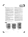
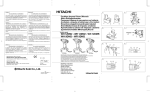
3. Installing the bit (WH12DAF2)
Always follow the following procedure to install driver
bit. (Fig. 5)
(1) Pull the guide sleeve away from front of the tool.
(2) Insert the bit into the hexagonal hole in the anvil.
(3) Release the guide sleeve and it returns to its original
position.
CAUTION:
If the guide sleeve does not return to its original
position, then the bit is not installed properly.
4. Selecting the socket matched to the bolt
(WR12DAF2)
Be sure to use a socket which is matched to the bolt
5.
䢇
(1)
(2)
(3)
䢇
to be tightened. Using an improper socket will not
only result in insufficient tightening but also in
damage to the socket or nut.
A worn or deformed hex. or square-holed socket will
not give an adequate tightness for fitting to the nut or
anvil, consequently resulting in loss of tightening
torque.
Pay attention to wear of socket hole, and replace
before further wear has developed.
Finally, install the socket prescribed in Item 5. The
section on “Optional Accessories” details the
relationship between bolt sizes and sockets. Sockets
are named according to the dihedral width of the
hexagonal hole.
Installing a socket (WR12DAF2)
Select the socket to be used.
Pin, O-ring type (Fig. 6 and 7)
Align the hole in the socket with the hole in the anvil
and insert the anvil into the socket.
Insert the pin into the socket.
Attach the ring to the groove on the socket.
Plunger type (Fig. 8)
Align the plunger located in the square part of the
anvil with the hole in the hex. socket. Then push the
plunger, and mount the hex. socket on the anvil.
Check that the plunger is fully engaged in the hole.
When removing the socket, reverse the sequence.
HOW TO USE
CAUTION:
䡬 When using the light equipped hook, pay sufficient
attention so that the main equipment does not fall. If
the tool falls, there is a risk of accident.
䡬 Do not attach the tip tool except phillips bit to the tool
main unit when carrying the tool main unit with the
light equipped hook suspended from a waist belt.
Injury may result if you carry the equipment
suspended from the waist belt with sharp tipped
components such as drill bit attached.
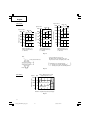
1. Using the light equipped hook
The light equipped hook can be installed on the right
or left side and the angle can be adjusted in 5 steps
between 0° and 80°.
(1) Operating the hook
(a) Pull out the hook toward you in the direction of
arrow (A) and turn in the direction of arrow (B).
(Fig. 9)
(b) The angle can be adjusted in 5 steps (0°, 20°, 40°,
60°, 80°).
Adjust the angle of the hook to the desired position
for use.
(2) Switching the hook position
CAUTION:
Incomplete installation of the hook may result in
bodily injury when used.
(a) Securely hold the main unit and remove the screw
using a slotted head screwdriver or a coin. (Fig.
10)
(b) Remove the hook and spring. (Fig. 11)
(c) Install the hook and spring on the other side and
securely fasten with screw. (Fig. 12)
NOTE:
Pay attention to the spring orientation. Install the
spring with larger diameter away from you. (Fig. 12)
8
01Eng_WH12DAF2_Eng_Spa
8
9/26/07, 19:12
English
(3) Using as an auxiliary light
(a) Press the switch to turn off the light.
If forgotten, the light will turn off automatically
after 15 minutes.
(b) The direction of the light can be adjusted within
the range of hook positions 1 - 5. (Fig. 13)
䡬 Lighting time
N manganese batteries: approx. 15 hrs.
N alkali batteries: approx. 30 hrs.
CAUTION:
Do not look directly into the light.
Such actions could result in eye injury.
(4) Replacing the batteries
(a) Loosen the hook screw with a phillips-head
screwdriver (No. 1). (Fig. 14)
Remove the hook cover by pushing in the direction
of the arrow. (Fig. 15)
(b) Remove the old batteries and insert the new
batteries. Align with the hook indications and
position the plus (+) and minus (–) terminals
correctly. (Fig. 16)
(c) Align the indentation in the hook main body with
the protuberance of the hook cover, press the
hook cover in the direction opposite to that of the
arrow shown in Fig. 15 and then tighten the screw.
Use commercially available N batteries
(1.5 V).
NOTE:
Do not tighten the screw excessively. Such action
could strip the screw threads.
CAUTION:
䡬 Failure to observe the following can result in battery
leakage, rust or malfunction.
Position the plus (+) and minus (–) terminals correctly.
Replace both batteries at the same time. Do not mix
old and new batteries.
Remove exhausted batteries from the hook
immediately.
䡬 Do not discard batteries together with normal trash
and do not throw batteries into fire.
䡬 Store batteries out of the reach of children.
䡬 Use batteries correctly in accordance with the battery
specifications and indications.
2. Check the rotational direction
The bit rotates clockwise (viewed from the rear side)
by pushing the R-side of the push button.
The L-side of the push button is pushed to turn the bit
counterclockwise. (See Fig. 17) (The L and R marks
are provided on the body.)
CAUTION:
The push button cannot be switched while the impact
driver is turning. To switch the push button, stop the
impact driver, then set the push button.
3. Switch operation
䡬 When the trigger switch is depressed, the tool rotates.
When the trigger is released, the tool stops.
䡬 The rotational speed can be controlled by varying the
amount that the trigger switch is pulled. Speed is low
when the trigger switch is pulled slightly and increases
as the trigger switch is pulled more.
4. Tightening and loosening screws (WH12DAF2)
Install the bit that matches the screw, line up the bit
in the grooves of the head of the screw, then tighten
it.
Push the impact driver just enough to keep the bit
fitting the head of the screw.
CAUTION:
Applying the impact driver for too long tightens the
screw too much and can break it.
Tightening a screw with the impact driver at an angle
to that screw can damage the head of the screw and
the proper force will not be transmitted to the screw.
Tighten with this impact driver lined up straight with
the screw.
5. Number of screws tightenings possible (WH12DAF2)
Please refer to the table below for the number of
screw tightened possible with one charge.
EB1214S
Screw used
No. of tightenings
Wood screw ø4 × 50
(Soft wood)
Approx. 190
Machine screw M8 × 16
Approx. 500
These values may vary slightly, according to
surrounding temperature and battery characteristics.
6. Number of bolt tightened possible (WR12DAF2)
Please refer to the table below for the number of bolt
tightened possible with one charge.
EB1214S
Bolt used
No. of tightenings
M12 × 45 High tension bolt
OPERATIONAL CAUTIONS
1. Resting the unit after continuous work
After use for continuous bolt-tightening work, rest
the unit for 15 minutes or so when replacing the
battery. The temperature of the motor, switch, etc.,
will rise if the work is started again immediately after
battery replacement, eventually resulting in burnout.
NOTE:
Do not touch the hammer case, as it gets very hot
during continuous work.
2. Cautions on use of the speed control switch
This switch has a built-in, electronic circuit which
steplessly varies the rotation speed. Consequently,
when the switch trigger is pulled only slightly (low
speed rotation) and the motor is stopped while
continuously driving in screws, the components of
the electronic circuit parts may overheat and be
damaged.
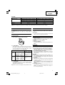
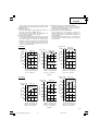
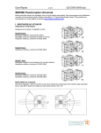
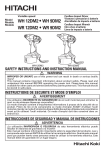
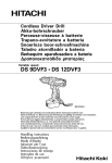
3. Tightening torque
Refer to Fig. 18 and Fig. 19 for the tightening torque
of bolts (according to size), under the conditions
shown in Fig. 20. Please use this example as a general
reference, as tightening torque will vary according to
tightening conditions.
9
01Eng_WH12DAF2_Eng_Spa
9
Approx. 87
These values may vary slightly, according to
surrounding temperature and battery characteristics.
NOTE:
The use of the battery EB1226HL in a cold condition
(below 0 degree Centigrade) can sometimes result in
the weakened tightening torque and reduced amount
of work. This, however, is a temporary phenomenon,
and returns to normal when the battery warms up.
9/26/07, 19:12
English
NOTE:
䡬 If a long striking time is used, screws will be strongly
tightened. This may cause the screw to break, or may
damage the tip of the bit.
䡬 If the unit is held at an angle to the screw being
tightened, the head of the screw may be damaged, or
the specified torque may not be transmitted to the
screw. Always keep the unit and the screw being
tightened in a straight line.
4. Use a tightening time suitable for the screw
The appropriate torque for a screw differs according
to the material and size of the screw, and the material
being screwed etc., so please use a tightening time
suitable for the screw. In particular, if a long tightening
time is used in the case of screws smaller than M8,
there is a danger of the screw breaking, so please
confirm the tightening time and the tightening torque
beforehand.
5. Work at a tightening torque suitable for the bolt
under impact
The optimum tightening torque for nuts or bolts differs
with material and size of the nuts or bolts. An
excessively large tightening torque for a small bolt
may stretch or break the bolt. The tightening torque
increases in proportion to the operation time. Use
the correct operating time for the bolt.
6. Holding the tool
Hold the impact wrench firmly with both hands. In
this case hold the wrench in line with the bolt.
It is not necessary to push the wrench very hard.
Hold the wrench with a force just sufficient to
counteract the impact force.
7. Confirm the tightening torque
The following factors contribute to a reduction of the
tightening torque. So confirm the actual tightening
torque needed by screwing up some bolts before the
job with a hand torque wrench. Factors affecting the
tightening torque are as follows.
(1) Voltage
When the discharge margin is reached, voltage
decreases and tightening torque is lowered.
(2) Operating time
The tightening torque increases when the operating
time increases. But the tightening torque does not
increase above a certain value even if the tool is
driven for a long time. (See Fig. 18 and 19)
(3) Diameter of bolt
The tightening torque differs with the diameter of the
bolt as shown in Fig. 18 and 19. Generally a larger
diameter bolt requires larger tightening torque.
(4) Tightening conditions
The tightening torque differs according to the torque
ratio; class, and length of bolts even when bolts with
the same size threads are used. The tightening torque
also differs according to the condition of the surface
of workpiece through which the bolts are to be
tightened. When the bolt and nut turn together, torque
is greatly reduced.
(5) Using optional parts (WR12DAF2)
The tightening torque is reduced a little when an
extension bar, universal joint or a long socket is
used.
(6) Clearance of the socket (WR12DAF2)
A worn or deformed hex. or a square-holed socket
will not give an adequate tightness to the fitting
between the nut or anvil, consequently resulting in
loss of tightening torque.
Using an improper socket which does not match to
the bolt will result in an insufficient tightening torque.
(7) Tightening torque varies, depending on the battery’s
charge level. (WR12DAF2)
Fig. 21 show examples of the relationship between
tightening torque and the number of tightenings, for
WR12DAF2. As shown, tightening torque gradually
weakens with the increase in the number of
tightenings. In particular, as the torque decreases
very close to the complete discharge (“a” margin in
graph), the unit’s impact weakens, the number of
time impacts declines and tightening torque drops
off abruptly. If this occurs, check torque level, then
recharge the battery if necessary.
〈WH12DAF2〉
kgf • cm N • m
1200 120
kgf • cm N • m
1000 100
kgf • cm N • m
1000 100
M8 × 30
High tension bolt
M10 × 30
1000 100
80
High tension bolt
600
60
400
40
200
20
80
600
60
400
40
200
20
0
0
Tightening torque
800
Tightening torque
Tightening torque
High tension bolt
800
M12 × 45
Ordinary bolt
800
80
600
60
400
40
200
20
0
0
Ordinary bolt
Ordinary bolt
0
0
0
1
2
3
Tightening time: sec.
(Steel plate thickness
t = 10 mm)
0
1
2
Tightening time: sec.
(Steel plate thickness
t = 10 mm)
3
0
1
2
3
Tightening time: sec.
(Steel plate thickness
t = 25 mm)
Fig. 18
10
01Eng_WH12DAF2_Eng_Spa
10
9/26/07, 19:12
English
kgf • cm N • m
1400 140
〈WR12DAF2〉
kgf • cm N • m
1200 120
M8 × 30
80
600
60
400
40
200
20
Tightening torque
Tightening torque
800
High tension
bolt
1000 100
High tension
bolt
800
80
600
60
400
40
200
20
0
0
High tension
1200 120 bolt
M10 × 30
Tightening torque
kgf • cm N•m
1000 100
Ordinary bolt
Ordinary bolt
0
0
0
1
2
3
Tightening time: sec.
(Steel plate thickness
t = 10 mm)
0
1
M12 × 45
2
1000 100
800
80
600
60
400
40
200
20
0
0
Ordinary bolt
3
0
Tightening time: sec.
(Steel plate thickness
t = 10 mm)
1
2
3
Tightening time: sec.
(Steel plate thickness
t = 25 mm)
Fig. 19
Bolt
*The following bolt is used.
Ordinary bolt: Strength grade 4.8
High tension bolt: Strength grade 12.9
Steel plate thickness t
(
Explanation of strength grade:
4 — Yield point of bolt: 32 kgf/mm2
8 — Pulling strength of bolt: 40 kgf/mm2
Nut
Fig. 20
〈WR12DAF2〉
Tightening torque
kgf•cm
1600
M12 × 45 High tension bolt
(tighening time 3 sec)
N •m
160
1200
a
120
800
80 When full recharged
400
40
0
0
When completely
discharged
0
20
40
60
80
100
Number of tightenings (PCS)/charging
Fig. 21
11
01Eng_WH12DAF2_Eng_Spa
11
9/26/07, 19:12
)
English
MAINTENANCE AND INSPECTION
1. Inspecting the driver bit (WH12DAF2)
Using a broken bit or one with a worn out tip is
dangerous because the bit can slip. Replace it.
2. Inspecting the socket (WR12DAF2)
A worn or deformed hex. or a square-holed socket
will not give an adequate tightness to the fitting
between the nut or anvil, consequently resulting in
loss of tightening torque. Pay attention to wear of a
socket holes periodically, and replace with a new one
if needed.
3. Inspecting the mounting screws
Regularly inspect all mounting screws and ensure
that they are properly tightened. Should any of the
screws be loose, retighten them immediately. Failure
to do so may result in serious hazard.
4. Cleaning of the outside
When the impact driver is stained, wipe with a soft
dry cloth or a cloth moistened with soapy water. Do
not use chloric solvents, gasoline or paint thinner, as
they melt plastics.
5. Storage
Store the impact driver in a place in which the
temperature is less than 40°C, and out of reach of
children.
6. Service parts list
A : Item No.
B : Code No.
C : No. Used
D : Remarks
CAUTION:
Repair, modification and inspection of Hitachi Power
Tools must be carried out by an Hitachi Authorized
Service Center.
This Parts List will be helpful if presented with the
tool to the Hitachi Authorized Service Center when
requesting repair or other maintenance.
In the operation and maintenance of power tools, the
safety regulations and standards prescribed in each
country must be observed.
MODIFICATIONS:
Hitachi Power Tools are constantly being improved
and modified to incorporate the latest technological
advancements.
Accordingly, some parts (i.e. code numbers and/or
design) may be changed without prior notice.
NOTE:
Due to HITACHI’s continuing program of research and
development, the specifications herein are subject to
change without prior notice.
12
01Eng_WH12DAF2_Eng_Spa
12
9/26/07, 19:12
Español
PRECAUCIONES GENERALES PARA
OPERACIÓN
¡ADVERTENCIA! Cuando utilice herramientas con pilas,
siga siempre las precauciones básicas relativas a la
seguridad para reducir el riesgo de incendio, la fuga de
las pilas y los daños personales, incluidos los siguientes.
Lea todas todas estas instrucciones antes de utilizar este
producto y guárdelas.
Para realiza roperaciones seguras:
1.
Mantener el área de trabajo limpia, áreas y bancos
de trabajo desordenados son causa de daños
personales.
2.
Tenga en cuenta el entorno de trabajo. No exponga
las herramientas a la lluvia. No utilice herramientas
en lugares húmedos o mojados. Mantenga el área
de trabajo bien iluminado.
No utilice las herramientas cuando haya riesgo de
incendio o explosión.
3.
Mantenga a los niños alejados del área de trabajo.
No deje que otras personas toquen la herramienta.
Toda persona ajena al trabajo debe mantenerse
alejada del área de trabajo.
4.
Guardar las pilas o herramientas que no se utilicen.
Cuando no se utilicen las herramientas y las pilas,
deben guardarse por separado en un lugar seco,
alto o con llave, fuera del alcance de los niños.
Asegúrese de que los terminales de las pilas no
pueden fundirse por otras piezas metálicas como
tornillos, clavos, etc.
5.
No forzar las herramientas, éstas trabajarán más
y con mayor seguridad cuando cumplan con las
especificaciones para las cuales fueron diseñadas.
6.
Utilice la herramienta adecuada. No fuerce
herramientas pequeñas o accesorios para hacer
el trabajo de herramientas de alta resistencia. No
utilice herramientas para fines para los que no
están diseñadas.
7.
Vestir apropiadamente. No ponerse ropas que
queden flojas ni tampoco joyas. Estas podrian
quedar atrapadas en las partes móviles de las
herramientas. Cuando se trabaje en exteriores, se
recomienda el uso de guantes de goma y calzado
que no resbale. Utilice elementos de protección
para sujetar el cabello largo.
8.
Utilice gafas de seguridad. Asimismo, utilice
mascarilla para el polvo o la cara si la operación
de cortado levanta mucho polvo.
9.
Conecte un equipo colector de polvo.
Si existen dispositivos para la conexión de equipos
de extracción y recolección de polvo, cerciórese
de queéstos estén conectados adecuadamente, y
de utilizarlos en la forma correcta.
10. No abuse del cable (si viene incorporado). No
transporte la herramienta con el cable o tire de
él para desconectarla del enchufe. Mantenga el
cable alejado de las fuentes de calor, el aceite y
bordes afilados.
11. Asegurar la pieza de trabajo usando para ello
abrazaderas o un tornillo. Esto es más seguro que
usar las manos, ademas, ambas manos quedan
libres para operar la herramienta.
12. No extenderse excesivamente para efectuar un
trabajo. Mantener en todo momento un buen
balance y base de apoyo.
13. Mantenga las herramientas con cuidado. Mantenga
las herramientas de cortado afiladas y limpias
para un funcionamiento mejor y más seguro. Siga
las instrucciones de lubricación y cambio de
accesorios. Inspeccione los cables de la
herramienta periódicamente y si están dañados,
llévelos a un servicio autorizado para que los
repare. Mantenga los mangos secos, limpios y
libres de aceite y grasa.
13
02Spa_WH12DAF2_Eng_Spa
13
14.
15.
16.
17.
18.
19.
䡬
䡬
䡬
䡬
20.
21.
22.
Desconecte las herramientas
Cuando el diseño lo permita, extraiga el paquete
de pilas de la herramienta cuando no la esté
utilizando, antes de realizar su mantenimiento o
cuando cambie accesorios como cuchillas, brocas
y cortadoras.
Quitar las cuñas y las llaves de tuercas.
Acostumbrarse a comprobar si se han quitado las
cuñas y las llaves de tuercas antes de poner las
harramientas en funcionamiento.
Evite que la herramienta se ponga en marcha
inesperadamente. No transporte la herramienta
con un dedo en el interruptor.
Estar siempre alerta y poner atención a lo que
se está haciendo, usar el sentido común y no
operar con la herramienta cuando se esté cansado.
Comprobar las piezas dañadas. Antes de seguir
con el funcionamiento de las herramientas, las
piezas que estén dañadas deberán comprobarse
cuidadosamente para determinar si pueden
funcionar apropiadamente y cumplir con la función
para las que fueron diseñadas. Comprobar el
alineamiento y agarrotamiento de piezas móviles,
rotura de piezas, montura, y cualiquier otra
anomalia que pudiese afectar al rendimiento de
la herramienta. Cualquier pieza que estuviese
dañada deberá repararse apropiadamente o
cambiarse en un centro de reparaciones autorizado,
al menos que se indique, lo contrario en este
manual de instrucciones. Deje que un servicio
autorizado sustituya los interruptores defectuosos.
No utilice la herramienta si el interruptor no la
enciende o apaga.
Advertencia
La utilización de cualquier accesorio o aditivo no
recomendado en este manual de instrucciones
puede conducir al riesgo de lesiones.
Asegúrese de que el paquete de pilas es correcto
para la herramienta.
Asegúrese de que la superficie externa del paquete
de pilas y la herramienta están limpias y secas
antes de enchufar el cargador.
Asegúrese de que las pilas están cargadas
utilizando el cargador correcto recomendado por
el fabricante. Una utilización incorrecta puede
causar una descarga eléctrica, un recalentamiento
o una fuga de líquido corrosivo de las pilas.
La herramienta debe ser reparada por una persona
cualificada.
Esta herramienta cumple los requisitos relevantes
sobre seguridad. Las reparaciones sólo deben
realizarse por personas cualificadas que utilicen
piezas de repuesto originales. De lo contrario, el
usuario podría estar expuesto a importantes
riesgos.
Desecho de las pilas
Asegúrese de que las pilas se desechan de forma
segura tal y como indica el fabricante.
Si se utilizan bajo condiciones abusivas, saldrá
líquido de las pilas. Evite el contacto.
Si ocurre esto, aclare con agua. Si entra líquido
en contacto con los ojos, acuda a su médico.
PRECAUCIONES PARA EL ATORNILLADOR DE
IMPACTO A BATERÍA
1.
2.
3.
Esta es una herramienta portátil para apretar y
aflojar tornillos. Empléela solamente para este fin.
Utilizar tapones en los oidos cuando se utilice la
herramienta durante un largo período de tiempo.
El empleo con una sola mano es extremadamente
peligroso; cuando utilice La unidad, sosténgala
firmemente con ambas manos.
9/26/07, 19:11
Español
4.
5.
6.
7.
8.
9.
10.
11.
12.
13.
14.
15.
Después de instalar la punta de destornillador, tire
ligeramente de la misma para asegurarse de que
no esté floja. Si no instala adecuadamente la
punta, es posible que ésta se afloje durante la
operación, lo que podría resultar peligroso.
Emplee la punta de destornillador adecuada al
tornillo.
El apretado angular de un tornillo con el
atornillador de impacto puede dañar la cabeza del
mismo, y es posible que a éste no se le transmita
la fuerza apropiada. Apriete con este atornillador
de impacto alineado con el tornillo.
Siempre cargar la batería a una temperatura de
0°C – 40°C.
Una temperatura inferior a 0°C causa una
sobrecarga, lo que es peligroso. No puede cargarse
la batería a una temperatura mayor de 40°C.
La temperatura más apropiada para cargar es la
de 20°C – 25°C.
No usar el cargador continuamente.
Cuando se completa la carga, dejar descansar el
cargador por 15 minutos antes de proseguir con
la carga siguiente.
No dejar que entre suciedad por el orificio de
conexión de la batería recargable.
Nunca desarmar la batería recargable ni el
cargador.
Nunca poner en cortocircuito la batería recargable.
Poner en cortocircuito a la batería produce una
corriente eléctrica enorme y el consecuente
recalentamiento, pudiendo quemar o deteriorar la
batería.
No tirar la batería al fuego.
Si se quema la batería puede explotar.
No insertar ningún objeto en las ranuras de
ventilación del cargador.
La penetración de objetos metálicos o inflamables
en dichas ranuras puede provocar electrochoques
o dañar el cargador.
Llevar la batería al sitio de compra original en el
caso de que la duración de la batería recargable
sea reducida al usarse. No tirar la batería
descargada.
El uso de una batería descargada dañará el
cargador.
PRECAUCIONES PARA LA LLAVE DE IMPACTO
A BATERÍA
1.
2.
3.
4.
5.
6.
Esta es una harramienta prtátil para apretar y
aflojar tornillos. Empléela solament para este fin.
Utilizar tapones en los oidos cuando se utilice la
herramienta durante un largo período de tiempo.
El empleo con una sola mano es extremadamente
peligroso; cuando utilice La unidad, sosténgala
firmemente con ambas manos.
Comprueba que el receptáculo no esté rajado ni
roto.
Los receptáculos rajados o rotos son peligrosos.
Compruébelos antes de emplearlos.
Sujete el receptáculo con el pasador y el anillo.
Si el pasador o el anillo de sujeción del receptáculo
está dañado, éste oye de salirse de la llave de
percusión, lo que puede resultar bastante peligroso.
No emplee pasadores ni anillos deformados,
gastados, rajados, ni con qualiquier otro daño.
Asegúrese siempre de instalar el apsador y el
anillo en la posición correcta.
Verifique el par de apriete. El par correcto para
apretar un perno dependerá del material dicho
perno, sus dimensiones, clase, etc.
Además, el par de apriete generado por esta llave
de percusión dependerá de los materiales y
dimensiones del perno, el tiempo que se aplique
la llava, la forma en la que se haya instalado el
receptáculo, etc.
7.
8.
9.
10.
11.
12.
13.
14.
15.
16.
17.
18.
Además, el par con la batería recién cargada y
con ella a punto de agatarse será ligeramente
diferente. Emplee una llave torsimétrica para
comprobar si el pernose ha apretado con el par
apropiado.
Antes de cambiar el sentodo de rotación para la
llave de percuión. Antes de cabiar el sentido de
rotación, suelte el interruptor y espere hasta que
la llave de percusión se pare.
No toque nunca las partes giratorias.
No permita que la sección del receptáculo entre
en contacto con sus manos ni con ninguna otra
parte del cuerpo. El receptáculo podría dañarle.
Además, tenga cuidado de no tocarlo después de
haberlo empleado continumente durante mucho
tiempo ya que estará caliente y podria porducirle
quemaduras.
No deje nunca que la llave de percusión gire sin
carge cuando emplee la junta cardáncica.
Si el receptáculo gira sin carge conectada, la junta
cardáncia hará que el receptáculo gire libremente,
en cuyo caso podría surfrir daños personales, o
las sacudidas del receptáculo podrían hacer que
la llave de percusión se cayese.
Siempre cargar la batería a una temperatura de
0°C – 40°C.
Una temperatura inferior a 0°C causa una
sobrecarga, lo que es peligroso. No puede cargarse
la batería a una temperatura mayor de 40°C.
La temperatura más apropiada para cargar es la
de 20°C – 25°C.
No usar el cargador continuamente.
Cuando se completa la carga, dejar descansar el
cargador por 15 minutos antes de proseguir con
la carga siguiente.
No dejar que entre suciedad por el orificio de
conexión de la batería recargable.
Nunca desarmar la batería recargable ni el
cargador.
Nunca poner en cortocircuito la batería recargable.
Poner en cortocircuito a la batería produce una
corriente eléctrica enorme y el consecuente
recalentamiento, pudiendo quemar o deteriorar la
batería.
No tirar la batería al fuego.
Si se quema la batería puede explotar.
No insertar ningún objeto en las ranuras de
ventilación del cargador.
La penetración de objetos metálicos o inflamables
en dichas ranuras puede provocar electrochoques
o dañar el cargador.
Llevar la batería al sitio de compra original en el
caso de que la duración de la batería recargable
sea reducida al usarse. No tirar la batería
descargada.
El uso de una batería descargada dañará el
cargador.
MODELO
WH12DAF2: con cargador y caja
WR12DAF2:con cargador y caja
14
02Spa_WH12DAF2_Eng_Spa
14
9/26/07, 19:11
Español
ESPECIFICACIONES
HERRAMIENTA MOTORIZADA
Modelo
Velocidad sin carga
Capacidad
Torsión de apriete
WH12DAF2
WR12DAF2
0/min – 2 500/min
M4 – M8 (Tornillo pequeño)
M6 – M14 (Perno ordinario)
M6 – M10 (Pernos de gran resistencia a la tracción)
M5 – M12 (Perno ordinario)
M5 – M10 (Pernos de gran resistencia a la tracción)
Máxima 110 N·m {1 120 kgf·cm}
Máxima 130 N·m {1 330 kgf·cm}
La torsión es de pernos M12 de gran
La torsión es de M12 Pernos de gran
resistencia a la tracción (división de
resistencia a la tracción (división de
dureza 12,9) con la batería
dureza 12,9), con la batería
completamente cargada a 20°C de
completamente cargada, a 20°C de
temperatura.
temperatura.
Tiempo de torsión: 3 seg.
Tiempo de torsión: 3 seg.
Batería recargable
EB1214S: Batería Ni-Cd, 12 V (1,4 Ah 10 elementos)
EB1220BL: Batería Ni-Cd, 12 V (2,0 Ah 10 elementos)
EB1226HL: Batería Ni-MH, 12 V (2,6 Ah 10 elementos)
1,6 kg (Instalación de EB1214S)
Peso
CARGADOR
Modelo
Tiempo de carga
Tensión de carga
Peso
UC14YFA
EB1214S: Aprox. 30 min. (a 20°C)
EB1220BL: Aprox. 50 min. (a 20°C)
EB1226HL: Aprox. 60 min. (a 20°C)
7,2 V – 14,4 V
0,6 kg
UC18YG
EB1214S: Aprox. 30 min. (a 20°C)
EB1220BL: Aprox. 50 min. (a 20°C)
×
7,2 V – 18 V
0,3 kg
“×” indica que el paquete de batería no es compatible con dicho cargador.
NOTA: El tiempo de carga puede variar de acuerdo con la temperatura ambiente y la tensión de la fuente de
alimentación.
Tamaño del accesorio
ACCESORIOS ESTÁNDAR
1. Cargador (UC14YFA o UC18YG) ............................... 1
2. Caja de plástico .......................................................... 1
Los accesorios están sujetos a cambio sin previo aviso.
17 mm
13 mm
12 mm
9 mm
Tipo-L
ACCESORIOS OPCIONALES
(de venta por separado)
1. Batterie (EB1214S, EB1220BL, EB1226HL)
Tipo-S
Lugar de compra
República de Corea,
Taiwán, Hong Kong,
República Popular de
China, República de
Singapur
Otras
regiones
diferentes a las
indicadas
más
arriba.
3. Para WR12DAF2
El WR12DAF2 es un atornillador cuadrado de 12,7.
Seleccione el receptáculo con el tamaño de accesorio
adecuado.
2. Para WH12DAF2
Hay dos tipos de tamaños de accesorios para la
broca del atornillador y el receptáculo. Consulte la
tabla de abajo y seleccione el tamaño del accesorio
para la broca del atornillador o el receptáculo
adecuado para su WH12DAF2.
Los accesorios estándar están sujetos a cambio sin previo
aviso.
APLICACIÓN
〈WH12DAF2〉
䡬 Apretado y aflojado de tornillos pequeños, pernos
pequeños, etc.
15
02Spa_WH12DAF2_Eng_Spa
15
9/26/07, 19:11
Español
〈WR12DAF2〉
䡬 Apretado y aflojado de cualquier tipo de pernos y
tuercas pasa aseguerar estructuras.
DESMONTAJE E INSTALACIÓN DE BATERÍA
1. Desmontaje de la batería
Sujetar firmemente el asidero y presionar el cierre de
la batería para desmontarla (Ver las Figs. 1 y 2).
PRECAUCIÓN:
No cortocircuitar nunca la batería.
2. Instalación de la batería
Insertar la batería observando sus polaridades (Ver
la Fig. 2).
CARGA
〈UC14YFA〉
Antes de utilizar la herramienta eléctrica, cargue la batería
de la siguiente manera.
1. Enchufe el cable de alimentación del cargador a un
tomacorriente de CA
Cuando haya conectado el enchufe del cargador a
una toma de la red, la lámpara piloto se encendrá en
rojo. (A intervalos de 1 segundo.)
2. Inserte la batería en el cargador
Inserte firmemente la batería en la dirección mostrada
en la Fig.3, hasta que entre en contacto con el fondo
del compartimiento del cargador.
PRECAUCIÓN:
䡬 Si inserta la batería al revés, no sólo será imposible
cargarlas, sino que también se podrán producir
problemas en el cargador, como la deformación del
terminal de recarga.
3. Carga
Cuando inserte una batería en el cargador, la carga
comenzará la lámpara piloto permanecerá
continuamente encendida en rojo.
Cuando la bateria se haya cargado completamente,
la lámpara piloto parpadeará en rojo. (A intervalos de
1 segundo.) (Vea las Tabla 1)
(1) Indicaciones de la lámpara piloto
Las indicaciones de la lámpara piloto mostradas en la
Tabla 1, se producirán de acuerdo con la condición
del cargador o de la batería.
Tabla 1
Indicaciones de la lámpara piloto
Se encenderá durante 0,5 segundos.
No se encenderá durante 0,5 segundos.
(Apagada durante 0,5 segundos)
Antes de la
carga
Parpadeo
(ROJA)
Durante la
carga
Iluminación
(ROJA)
Carga
completa
Parpadeo
(ROJA)
Se encenderá durante 0,5 segundos.
No se encenderá durante 0,5 segundos.
(Apagada durante 0,5 segundos)
Carga
imposible
Parpadeo
(ROJA)
Se encenderá durante 0,1 segundos.
No se encenderá durante 0,1 segundos.
(Apagada durante 0,1 segundos)
Carga
imposible
Iluminación
(VERDE)
Illuminación permanente
Iluminación permanente
(2) Temperatura de las baterías
La temperatura de las baterías se muestra en la tabla
siguiente, y las baterías que se hayan calentado
deberán dejarse enfriar durante cierto tiempo antes
de cargarlas.
Tabla 2 Márgenes de carga de las baterías
Batería
EB1214S, EB1220BL
EB1226HL
Temperatura con la
que podrá cargarse
la batería
–5°C – 60°C
0°C – 45°C
4. Desenchufe el cable de alimentación del cargador
del tomacorriente de c.a.
5. Sostenga el cargador firmemente y saque la batería
02Spa_WH12DAF2_Eng_Spa
16
Mal funcionamento de
la batería o del
cargador
La température de la
batería es alta, lo que
imposibilita la carga.
NOTA:
Asegúrese de extraer la batería del cargador después
del uso, y guárdela después.
Descarga eléctrica en caso de baterías nuevas, etc.
Como la substancia química interna de las baterías
nuevas o las que no se hayan utilizado durante mucho
tiempo no está activada, la descarga eléctrica puede
ser inferior cuando se utilicen por primera y segunda
vez. Este fenómeno es temporal, y el tiempo normal
requerido para la recarga se restablecerá recargando
las baterías 2 – 3 veces.
Forma de hacer que las baterías duren más
(1) Recargue las baterías antes de que se hayan agotado
completamente.
Si siente que la potencia de la herramienta eléctrica
se debilita, deje de utilizarla y recargue la batería. Si
continuase utilizando la herramienta hasta agotar la
16
9/26/07, 19:11
Español
capacidad de la batería, ésta podría dañarse y su
duración útil podría acortarse.
(2) Evite realizar la recarga a altas temperaturas.
Una batería se calentará inmediatamente después de
haberla utilizado. Si recargase tal batería
inmediatamente después de haberla utilizado, su
substancia química interna se deterioraría, y la
duración útil de la batería se acortaría. Deje la batería
y recárguela después de que se haya enfriado durante
cierto tiempo.
PRECAUCIÓN:
䡬 Si carga la batería mientras esté caliente por haber
estado mucho tiempo en un lugar sometido a la luz
solar directo, o por haber acabado de utilizarla, es
posible que la lampara piloto del cargador se encienda
en verde. En tales casos, deje primero que se enfríe
la batería e inicie luego la carga.
䡬 Cuando la lámpara piloto parpadee rápidamente en
rojo (a intervalos de 0,2 segundos), realice una
comprobación y extraiga los objetos extraños del
orificio de instalación de batería del cargador. Si no
hay ningún objeto extraño, es posible que la batería
o el cargador funcione mal: Llévelos a un agente de
servicio técnico autorizado.
䡬 Como el microcomputador incorporado tarda unos 3
segundos en confirmar que se extraído la batería
cargada con el UC14YFA, espere por lo menos 3
segundos antes de volverla a insertar para continuar
cargando. Si reinserta la batería antes de 3 segundos,
es posible que no se cargue adecuadamente.
〈UC18YG〉
Antes de utilizar la herramienta eléctrica, cargue la batería
de la siguiente manera.
1. Conectar el cable de alimentación del cargador a la
toma de CA
Al conectar el cable de alimentación se encenderá el
cargador.
2. Insertar la batería en el cargador
Inserte firmemente la batería prestando atención a la
orientación, hasta que entre en contacto con la parte
inferior del cargador (la lámpara piloto se ilumina)
(Véase Figs. 4).
PRECAUCIÓN
Si no se enciende la lámpara piloto, desenchufar
el cable de alimentación de la toma de la red
y verificar la condición de montaje de la batería.
䡬 Temperatura de las baterías
Las temperaturas de las pilas recargables se indican
en la Tabla 3.
Tabla 3 Márgenes de carga de las baterías
Baterías
EB1214S, EB1220BL
Temperatura con
la que podrá
cargarse la batería
0°C – 45°C
䡬 La lámpara piloto se apaga para indicar que la batería
está completamente cargada.
El tiempo de carga será más largo a temperatura
baja o si la tensión de la fuente de alimentación es
demasiado baja.
Cuando la lámpara piloto no se apague incluso
cuando hayan transcurrido más de 120 minutos
después de haberse iniciado la carga, pare ésta y
póngase en contacto con un CENTRO DE SERVICIO
AUTORIZADO POR HITACHI.
PRECAUCIÓN
Si se calienta la batería debido a la luz directa
del sol etc, justo antes la operación, la lámpara
piloto del cargador puede que no se ilumine.
En este caso, enfriar primero la batería y a
continuación empezar a cargar.
3. Desenchufe el cable de alimentación del cargador
del tomacorriente de c.a.
4. Sostenga el cargador firmemente y saque la batería
NOTA
Después de la operación de carga, extraiga primero
las baterías del cargador y guárdelas adecuadamente.
Descarga eléctrica en caso de baterías nuevas, etc.
Como la substancia química interna de las baterías
nuevas o las que no se hayan utilizado durante mucho
tiempo no está activada, la descarga eléctrica puede
ser inferior cuando se utilicen por primera y segunda
vez. Este fenómeno es temporal, y el tiempo normal
requerido para la recarga se restablecerá recargando
las baterías 2 – 3 veces.
Forma de hacer que las baterías duren más.
(1) Recarque las baterías antes de que se hayan agotado
completamente.
Si siente que la potencia de la herramienta eléctrica
se debilita, deje de utilizarla y recargue su batería. Si
continuase utilizando la herramienta hasta agotar la
capacidad de la batería, ésta podría dañarse y su
duración útil podría acortarse.
(2) Evite realizar la recarga a altas temperaturas
Una batería se calentará inmediatamente después de
haberla utilizado. Si recargase tal batería
inmediatamente después de haberla utilizado, su
substancia química interna se deterioraría, y la
duración útil de la batería se acortaría. Deje la batería
y recárguela después de que se haya enfriado durante
cierto tiempo.
ANTES DE USAR LA HERRAMIENTA
1. Preparación y comprobación de las condiciones
ambientales de trabajo
Asegúrese de que el sitio de trabajo cumpla todas las
condiciones indicadas en las precauciones.
2. Comprobación de la batería
Asegúrese de que la batería esté firmemente
instalada. Si está floja, puede caerse y provocar
accidentes.
3. Instalación de la punta de destornillador (WH12DAF2)
Para instalar la punta de destornillador, realice
siempre el procedimiento siguiente. (Fig. 5)
(1) Tire del manguito guía alejándolo de la parte delantera
de la herramienta.
(2) Inserte la punta de destornillador en el orificio
hexagonal en el yunque.
(3) Suelte el manguito guía y devuélvalo a su posición
original.
PRECAUCIÓN:
Si el manguito guía no vuelve a su posición original,
significará que la punta de destornillador no está
correctamente instalada.
4. Selección del recepráculo que concuerde con el perno
(WR12DAF2)
Cerciorarse de utilizar un receptáculo que concuerde
con el perno a ser apretado. Si se utilizase un
17
02Spa_WH12DAF2_Eng_Spa
17
9/26/07, 19:12
Español
5.
䢇
(1)
(2)
(3)
䢇
receptáculo inadecuado, el apriete no será
satisfactorio y la cabeza el perno o la tuerca se
dañarán.
Un receptáculo, hexagonal o cuadrado, deformado
no quedará bien apretado en la tuerca o en el yunque
por lo que la tensión de apriete no será la adecuade.
Poner atención al desgaste de los agujeros del
receptáculo y cambiarlo antes de que el destaste sea
excesivo.
Finalmente, instale el receptáculo prescrito en el item
5. En la seción de “Accesorios opcionales” se ofrecen
los detalles sobre la relación entre el tamaño de los
pernos y los receptáculos. Los receptávculos se
denominan de acuerdo con la distancia entre las
superficies opuestas del orificio hexagona.
Instalacón de un receptáculo (WR12DAF2)
Seleccione el receptáculo que desee emplear.
Pasador, junta tórica (Figs. 6 y 7)
Alinee el orificio del receptaáculo con el del yunque
en enserte éste en el primero.
Inserte el pasador en el orificio del receptáculo.
Fije el anillo a la ranura del receptáculo.
Tipo émbolo (Fig. 8)
Alinee el émbolo sitado en la parte cuadrada de la
boca con el orificio del cuo hexagonal. Después
empuje el émbolo y monte el cubo hexagonal en la
boca. Compruebe que el émbolo esté completamente
enganchada en el orificio. Para extraer el cubo invierta
la secuencia.
COMO SE USA
PRECAUCIÓN:
䡬 Cuando utilice el gancho equipado con luz, preste
atención para que la unidad no se caiga. La caída de
la herramienta implica el riesgo de accidentes.
䡬 Cuando lleve la unidad principal de la herramienta
provista de gancho equipado con luz colgada del
cinturón, evite fijar puntas de herramienta, a
excepción de una broca Phillips.
Sì llevara el equipo colgado del cinturón con una
broca de barrena u otros componentes de extremo
afilado fijado al mismo, se podrían producir lesiones.
1. Uso del gancho equipado con luz
El gancho equipado con luz puede instalarse en el
lateral derecho o izquierdo, y el ángulo puede
ajustarse en 5 pasos, entre 0° y 80°.
(1) Operación del gancho
(a) Extraiga el gancho hacia sí en la dirección de la
flecha (A) y gírelo en la dirección de la flecha (B).
(Fig. 9)
(b) El ángulo se puede ajustar en 5 pasos (0°, 20°,
40°, 60°, 80°).
Ajuste el ángulo del gancho en la posición
conveniente para el uso.
(2) Cambio de la posición del gancho
PRECAUCIÓN:
La instalación incompleta del gancho puede provocar
lesiones corporales durante el uso.
(a) Sujete firmemente la unidad principal y saque el
tornillo usando un destornillador de cabeza
ranurada o una moneda. (Fig. 10)
(b) Saque el gancho y el resorte. (Fig. 11)
(c) Instale el gancho y el resorte en el otro lateral y
asegure firmemente con el tornillo. (Fig. 12)
NOTA:
Preste atención a la orientación del resorte. El
diámetro más grande debe quedar opuesto a usted.
(Fig. 12)
(3) Empleo como luz auxiliar
(a) Presione el interruptor para apagar la luz.
Si se olvida de apagar la luz, la misma se apagará
automáticamente al cabo de 15 minutos.
(b) La dirección de la luz se puede ajustar dentro del
alcance de las posiciones 1 - 5 del gancho. (Fig.
13)
䡬 Tiempo de iluminación
Pilas de manganeso N: aprox. 15 h
Pilas alcalinas N: aprox. 30 h
PRECAUCIÓN:
No mire directamente hacia la luz.
Tal acción podría dañar la vista.
(4) Sustitución de las pilas
(a) Afloje el tornillo de gancho con un destornillador
tipo Phillips (Núm.1) (Fig. 14)
Quite la tapa del gancho empujando en la dirección
de la flecha. (Fig. 15)
(b) Retire las pilas usadas e introduzca las pilas
nuevas. Alineélas con las indicaciones del gancho
y posicione correctamente los terminales positivo
(+) y negativo (–). (Fig. 16)
(c) Haga coincidir la muesca del cuerpo principal del
gancho con el saliente de la tapa del gancho,
presione la tapa en la dirección opuesta a la flecha
mostrada en la Fig. 15 y apriete el tornillo.
Utilice pilas N (1,5 V c.d.) disponibles en los
establecimientos del ramo.
NOTA:
No apriete los tornillos excesivamente, pues se
podrían dañar las roscas de los tornillos.
PRECAUCIÓN:
䡬 La negligencia en la observación de las siguientes
precauciones puede provocar fugas de electrólito,
oxidación o fallos de funcionamiento.
Posicione correctamente los terminales positivo (+) y
negativo (–).
Siempre cambie ambas pilas a la vez. No mezcle
pilas nuevas con pilas usadas.
Las pilas agotadas deben ser retiradas
inmediatamente del gancho.
䡬 No descarte las pilas junto con la basura normal y no
las arroje al fuego.
䡬 Guarde las pilas fuera del alcance de los niños.
䡬 Utilice las pilas correctamente, de acuerdo con las
especificaciones e indicaciones provistas con las
mismas.
2. Comprobación de la dirección de rotación
La broca gira hacia la derecha (vista desde atrás) al
oprimir el lado R (dcha.) del botón pulsador. El lado
L (izda.) del botón pulsador se utiliza para hacer que
la broca gire hacia la izquierda. (Vea la Fig. 17) (Las
marcas L y R están en el cuerpo.)
PRECAUCIÓN:
El botón pulsador no podrá accionarse mientras la
herramienta esté en funcionamiento. Para accionar
el botón pulsador, pare en primer lugar la
herramienta, y después presione el botón pulsador.
3. Operación de conmutación
䡬 Cuando apriete el disparador, la herramienta girará.
Al soltar el disparador, la herramienta se parará.
18
02Spa_WH12DAF2_Eng_Spa
18
9/26/07, 19:12
Español
䡬 La velocidad de rotación podrá controlarse variando
la presión de apriete del disparador. La velocidad
será lenta cuando se apriete ligeramente el
disparador, y aumentará a medida que lo apriete
más.
4. Apretado y aflojado de pernos (WH12DAF2)
Instale la punta de atornillador adecuada al tornillo,
alinéela con las ranuras de la cabeza del mismo, y
después apriételo.
Empuje el atornillador de percusión lo
suficientemente como para que la punta de
destornillador encaje en la cabeza del tornillo.
PRECAUCIÓN:
Si aplica demasiado tiempo el atornillador de impacto
sobre el tornillo, éste se apretará demasiado y se
romperá.
Apriete los tornillos con el ángulo que no dañe sus
cabezas y de forma que se pueda aplicar la fuerza
apropiada.
Apriete con el atornillador de impacto alineado con
el tornillo.
5. Número posible de aprietes (WH12DAF2)
Con respecto al número de aprietes de tornillos con
una carga, consultar la tabla siguiente.
EB1214S
Tornillos utilizados
N° de aprietes
Tornillo para madera ø4 × 50
(Madera blanda)
Aprox. 190
Tornillo para metales M8 × 16
Aprox. 500
Estos valores pueden variar ligeramente de acuerdo
con la temperatura ambiental y las características de
la batería.
6. Número posible de aprietes (WR12DAF2)
Con respecto al número de aprietes de tornillos con
una carga, consultar la tabla siguiente.
EB1214S
Perno utilizados
N° de aprietes
Perno de alta tensión M12 × 45
Circa. 87
Estos valores pueden variar ligeramente de acuerdo
con la temperatura ambiental y las características de
la batería.
NOTA:
La utilización de la batería EB1226HL en lugares fríos.
(menos de 0 grados centigrados) puede resultar a
veces en la reducción del par de apriete y el
rendimiento del trabajo. Sin embargo, éste es un
fenómeno temporal y, cuando la batería se caliente,
volverá a la normalidad.
PRECAUCIONES OPERACIONALES
1. Reposo de la herramienta después de un
funcionamiento prolongado
Tras una tarea de apriete de pernos de larga duración,
deje la unidad en reposo durante unos 15 minutos al
reemplazar la batería. Si reinicia la tarea
inmediatamente después de reemplazar la batería,
aumentaría la temperatura del motor, del interruptor,
etc., con los consiguientes riesgos de quemadura.
NOTA:
No toque la caja del martillo, ya que se recalienta
mucho durante el trabajo continuo.
2. Precauciones sobre el empleo del interruptor de
control de velocidad
Este interruptor posee un circuito electrónico
incorporado que varía la velocidad de rotación. Por
consiguiente, cuando apriete el gatillo sólo
ligeramente (baja velocidad de rotación) y el motor
se pare mientras esté insertando continuamente
tornillos, los componentes de dicho circuito
electrónico pueden recalentar y dañarse.
3. Par de apriete
Con respecto al par de apriete de los pernos (según
el tamaño), refiérase a las Figs. 18 y 19, bajo las
condiciones mostradas en la Fig. 20. Emplee este
ejemplo como referencía general, ya que el par de
apriete variará de acuerdo con las condiciones de
apriete.
NOTA:
䡬 Si emplea un tiempo de golpeteo largo, los tornillos
se apretarán fuertemente. Esto puede causar la rotura
de los tornillos, o el daño del extremo de la punta del
destornillador.
䡬 Si mantiene la unidad inclinada con respecto al tornillo
que esté apretando, la cabeza del mismo puede
dañarse, o es posible que el par de apriete no se
transmita al mismo. Mantenga siempre en línea recta
la unidad y el tornillo que esté apretando.
4. Emplee el tiempo de apriete adecuado al tornillo
El par adecuado a un tornillo difiere de acuerdo con
el material y el tamaño del mismo, el material en el
que se esté atornillando, etc. Por lo tanto, emplee el
tiempo de apriete adecuado al tornillo. En especial,
en caso de tornillos menores a M8 si utiliza un tiempo
de apriete largo, existe el peligro de rotura de los
tornillos, motivo por el que se le aconseja confirmar
con antelación el tiempo y el par de apriete.
5. Tensiónde apriete apropiada para los pernos y tuercas
La tensión de apriete óptima para pernos y tuercas
difiere según su material y tamaño. Una tensión de
apriete excesiva para un perno pequeño podría
deformarlo o romperlo. La tensión de apriete aumenta
proporcionalmente al teimpo de operación. Utilice la
indicación de la escala y el tiempo de operación
adecuados a cada perno.
6. Sufeción de la herramienta
Subjetar firmemente el aprietatuercas neumático de
percusión con ambas manos, sujetando el asa del
cuerpo y el asa lateral, y ponerlo en línea con el perno.
No es necesario presionar el aprietatuercas
excesivamente. Sufetar el aprietatuercas con una
tuerza equivalente a la fuerza de apriete.
7. Confirmación de la tensión de apriete
Los factores que se mencionen a continuación
contribuyen a reducir la tensión de apriete.
Comprobar por ello la tensión de apriete necesaria
atornillando previamente algunos tornillos con una
llave de tuercas manual. Factores que afectan a la
tensión de apriete.
(1) Tensión
Cuando se alcance el margen de descarga, la tensión
se reducirá y la torsión de apriete disminuirá.
(2) Tiempo de operación
La tensión de apriete aumenta al aumentar el tiempo
de operación. La tensión de apriete sin embargo no
19
02Spa_WH12DAF2_Eng_Spa
19
9/26/07, 19:12
Español
supera cierto valor a pesar de que la herramienta
funcione durante un largo periodo de tiempo. (Véase
Figs. 18 y 19)
(3) Diámetro del perno
El par de apriete difiere según el diámetro del perno,
tal como se muestra en la Figs. 18 y 19.
Generalmente, cuanto mayor sea el diámetro del
perno, mayor será la tensión de apriete.
(4) Condiciones de apriete
La tensión de apriete difiere según la clase y longitud
de los tornillos; a pesar de que éstos tengan la rosca
del mismo tamaño. La tensión de apriete difiere
también según las condiciones de las superficies del
metal en el cual van a apretarse los pernos. Cuando
el perno y la tuerca giran conjuntamente, el par se
reduce considerablemente.
(5) Utilización de piezas opcionales (WR12DAF2)
La tensión de apriete se reduce un poco cuando se
utiliza una barra de extensión, una junta universal o
un receptáculo de gran tamaño.
(6) Holgura del receptáculo (WR12DAF2)
Un receptáculo con sus agujeros hexagonal o
cuadrado deformados no quedará bien sujeto a la
tuerca o al yunque por lo que la tensión de apriete no
será apropiada.
Un receptáculo inapropiado, que no concuerde con
el perno, tembién evitará que la tensión de apriere
sea adecuada.
〈WH12DAF2〉
kgf • cm N • m
1 200 120
80
600
60
400
40
200
20
Perno de gran resistencia a la tracción
800
80
600
60
400
40
200
0
M10 × 30
Perno de gran resistencia a la tracción
1 000 100
Torsión de apriete
800
kgf • cm N • m
1 000 100
M8 × 30
Torsión de apriete
Torsión de apriete
kgf • cm N • m
1 000 100
M12 × 45
Perno de gran resistencia a la tracción
800
80
600
60
400
40
20
200
20
0
0
0
Perno ordinario
Perno ordinario
Perno ordinario
0
0
0
1
2
3
Tiempo de apriete: seg
(Grosor de la plancha de
acero t = 10 mm)
0
1
2
3
Tiempo de apriete: seg
(Grosor de la plancha
de acero t = 10 mm)
0
1
2
3
Tiempo de apriete: seg
(Grosor de la plancha
de acero t = 25 mm)
Fig. 18
kgf • cm N • m
1 400 140
〈WR12DAF2〉
kgf cm N m
1 200 120
•
80
600
60
400
40
200
20
0
0
1
2
1 200 120
1 000 100
Perno ordinario
0
M10 × 30
3
Tiempo de apriete: seg
(Grosor de la plancha
de acero t = 10 mm)
800
80
600
60
400
40
200
20
0
0
M12 × 45
Perno de gran resistencia a la tracción
Perno de gran resistencia a la tracción
Torsión de apriete
800
M8 × 30
Perno de gran
resis-tencia a la
tracción
Torsión de apriete
Torsión de apriete
kgf • cm N•m
1 000 100
•
Perno ordinario
0
1
2
3
Tiempo de apriete: seg
(Grosor de la plancha
de acero t = 10 mm)
1 000 100
800
80
600
60
400
40
200
20
0
0
Perno ordinario
0
1
2
3
Tiempo de apriete: seg
(Grosor de la plancha
de acero t = 25 mm)
Fig. 19
20
02Spa_WH12DAF2_Eng_Spa
20
9/26/07, 19:12
Español
(7) La torsión de apriete variará de acuerdo con el nivel
de cauga de la batería. (WR12DAF2)
En las Figs 21 se muestran ejemplos de la relación
entre el par de apriete y el número de aprietes para
WR12DAF2. Como indica la figura, la torsión de apriete
disminuirá grandualmente a medida que aumente el
número de aprientes. En particular, cuando el nivel
de la baatería se acerque a la descarga completa
Perno
(margen “a” del gráfico), la fuerza de percusión de la
herramienta se debilitará, el número de percusiónes
disminuirá, y la torsión de apriete caerá rápidamente.
Cuando ocurra esto, compruebe la torsión de apriete
y, si necesario, recargue la batería.
* Se emplean los pernos siguientes
Perno ordinario: Divisón de dureza 4,8
Perno de gran resistencia a la tracción: División
de dureza 12,9
Grosor de la plancha
de acero t
(
Explicación de la clasificación de la resistencia:
4 — Punto de relajamiento del perno: 32 kgf/mm2
8 — Resistencia a la tracción del perno: 40 kgf/mm2
)
Tuerca
Fig. 20
〈WR12DAF2〉
Torsión de apriete
kgf•cm
1 600
1 200
N•m
160
M12 × 45 Pernos de gran
resistencia a la tracción
(Tiempo de apriete 3 seg.)
a
120
800
Con la batería
80 completamente cargada
400
40
0
0
0
Con la batería
completamente
descargada
20
40
60
80
100
Número de aprietes (piezas)/carga
Fig. 21
MANTENIMIENTO E INSPECCIÓN
1. Inspección de las puntas de atornillador (WH12DAF2)
El empleo de una punta rota o desgastada es peligroso
porque ésta podría deslizarse. Reemplácela.
2. Inspección del receptáculo (WR12DAF2)
Un receptáculo con sus agujeros hexagonal o
cuadrado deformados no quedará bien sujeto a tuerca
o al yunque por lo que la tensión de apriete no será
apropida. Periódicamente, poner atención al desgaste
de los agujeros del receptáculo y cambiarlo por otro
nuevo cuando sea necesario.
3. Inspeccionar los tornillos de montaje
Regularmente inspeccionar todos los tornillos de
montaje y asegurarse que estén apretados
firmemente. Si cualquier tornillo estuviera suelto,
volver a apretarlo inmediatamente. El no hacer esto
provocaría un riesgo serio.
4. Limpieza en el exterior
Cuando el atornillador de impacto a batería esté sucio,
limpiarlo con un paño suave y seco o con un paño
mojado en agua jabonosa. No utilizar disolventes
clóricos, gasolina o disolventes parapinturas ya que
éstos funden los materiales plásticos.
5. Almacenamiento
Guarde el atornillador de impacto a batería en un
lugar en el cual la temperatura sea inferior a 40°C y
esté alejado del alcance de los niños.
6. Lista de repuestos
A : N°. ítem
B : N°. código
C : N°. usado
D : Observaciones
21
02Spa_WH12DAF2_Eng_Spa
21
9/26/07, 19:12
Español
PRECAUCIÓN:
La reparación, modificación e inspección de las
herramientas eléctricas Hitachi deben ser realizadas
por un Centro de Servicio Autorizado de Hitachi.
Esta lista de repuestos será de utilidad si es presentada
junto con la herramienta al Centro de Servicio
Autorizado de Hitachi, para solicitar la reparación o
cualquier otro tipo de mantenimiento.
En el manejo y el mantenimiento de las herramientas
eléctricas, se deberán observar las normas y
reglamentos vigentes en cada país.
MODIFICACIONES:
Hitachi Power Tools introduce constantemente
mejoras y modificaciones para incorporar los últimos
avances tecnológicos.
Por consiguiente, algunas partes (por ejemplo,
números de códigos y/o diseño) pueden ser
modificadas sin previo aviso.
NOTA:
Debido al programa continuo de investigación y desarollo
de HITACHI estas especificaciones están sjuetas a cambio
sin previo aviso.
22
02Spa_WH12DAF2_Eng_Spa
22
9/26/07, 19:12
23
03Back_WH12DAF2_Eng_Spa
Page 23
07.9.26, 19:20
Adobe PageMaker 6.5J/PPC
B
C
1-1 323-939 1
1-2 324-854 1
2
315-984 1
3
315-983 1
4
320-409 1
5
323-954 1
6
992-630 4
7
323-940 1
8
319-535 1
9-1 321-884 1
9-2 321-915 1
10 959-154 2
11 323-949 1
12 321-934 28
13 315-978 1
14 323-944 1
15 316-172 1
15 316-172 1
16 316-171 1
17 323-945 1
18 323-941 2
19 323-942 2
20 323-946 1
21 319-911 1
22 690-1VV 1
23 323-947 1
24 321-894 1
25 321-893 1
26 323-948 1
27 321-876 1
28 321-877 1
29 302-086 7
30 ––––––––––– 1
31 324-855 1
32 321-917 1
33 321-871 1
34 ––––––––––– 1
35 ––––––––––– 1
36 321-918 1
37 321-672 2
38 320-288 1
A
WH12DAF2
D
" 37, 38"
D2 × 6
M5
115L
60L
D4 × 20
6901VVCMPS2L
D3
S TYPE
D5.556
D3.5
D4 × 40
"2-5, 7-25"
S TYPE "2-5, 7-25"
B
306-952
323-710
320-777
320-776
319-926
319-927
–––––––––––
–––––––––––
–––––––––––
–––––––––––
–––––––––––
324-359
322-611
A
39
40
41
42
43
44
45-1
45-2
45-3
501-1
501-2
502-1
502-2
1
1
1
1
1
1
1
1
1
1
1
1
1
C
"GBR"
M5
EB1214S
EB1220BL
EB1226HL
UC18YG
UC14YFA
D
U
J
3
L
C
1
1
1
1
1
1
1
1
1
(B)
(A)
V
V
B
319-926
319-927
–––––––––––
–––––––––––
–––––––––––
–––––––––––
–––––––––––
324-359
322-611
2
R
"GBR"
4
17
M5
EB1214S
EB1220BL
EB1226HL
UC18YG
UC14YFA
10
5
D
9
Insertar
5
Pull out
Sacar
6
Insert
Insertar
7
Pilot lamp
Lámpara piloto
8
Hole for connecting the
rechargeable battery
Agujero para conectar la batería
recargable
9
Movement
Movimiento
0
Guide sleeve
Manguito guía
A
Hexagonal hole in the anvil
14
13
Orificio hexagonal en el yunque
B
Driver bit
Punta de destornillador
C
Hexagonal socket
3
Recaptáculo hexanogal
D
Groove
M
Ranura
E
Anvil
Yunque
F
Pin
Pasador
G
Ring
Anillo
H
Hole
O
Orificio
I
Plunger
J
Embolo
J
Hook
J
16
15
N
Gancho
K
Spring
Resorte
L
Larger diameter faces away
El diámetro más grande queda en
dirección opuesta
J
M
Switch
Interruptor
N
Phillips-head screwdriver
, .
P
Destornillador con cabeza Phillips
O
Screw
Tornillo
P
Arrow
R
S
Flecha
Q
Hook cover
Cubierta del gancho
R
Indentation
Indentación
S
Protuberance
T
S
Saliente
T
N batteries
Pilas N
U
Push button
. ,
Q
R
Q
Pulsador
V
Push
Presionar
3
" 33, 34"
D2 × 6
M5
Insert
115L
60L
D4 × 20
Mango
4
6901VVCMPS2L
Enganche
Handle
D3
Latch
3
D5.556
2
C
1
4
1
1
1
1
2
1
28
1
1
1
1
1
2
2
1
1
1
1
1
1
1
1
1
7
1
1
1
1
1
1
2
1
1
1
1
1
Español
Batería recargable, 12 V
L
K
2
English
12 V Rechargeable battery
B
324-856
992-630
324-857
323-194
323-193
323-192
959-154
323-949
321-934
315-978
323-944
316-172
316-171
323-945
323-941
323-942
323-946
319-911
690-1VV
323-947
321-894
321-893
323-948
321-876
321-877
302-086
–––––––––––
324-855
321-917
321-871
–––––––––––
321-918
321-672
320-288
306-952
323-710
320-777
320-776
J
1
A
1
2
3
4
5
6
7
8
9
10
11
12
13
14
15
16
17
18
19
20
21
22
23
24
25
26
27
28
30
31
29
32
33
34
35
36
37
38
12
WR12DAF2
11
D
"3-22"
D4 × 40
A
39
40
41-1
41-2
41-3
501-1
501-2
502-1
502-2
1
24
1
2
3
4
Cordless Impact Driver/Wrench
Atornillador/Llave de impacto a batería
1
1
3
2
2
4
1
WH 12DAF2 • WR 12DAF2
7
5
1
6
6
8
8
7
〈UC14YFA〉
5
B
WH12DAF2
6
9
E
0
WR12DAF2
8
C
Read through carefully and understand these instructions before use.
Leer cuidadosamente y comprender estas instrucciones antes del uso.
C
Handling instructions
Instrucciones de manejo
711
Code No. C99141441
Printed in China
D
A
7
Hitachi Koki Co., Ltd.
C
〈UC18YG〉
1
F
G
E
H I
E