1
MANUAL DE INSTRUCCIONES
INSTRUCTION MANUAL
Tamaños 07…12
Size 07…12
00.F0.200-KS19
KEB COMBIVERT F0 V1.2
02/93
©
KEB
00.F0.0EB-K120
02/93
COMBIVERT F0
Índice de contenido
Table of Contents
1.
1.1
1.2
1.3
1.4
1.5
1.6
1.7
1.7.1
1.7.2
1.7.3
1.8
Generalidades
Conexionado
Corriente de fuga-disyuntor diferencial (FI)
Protección del motor
Instrucciones de utilización
Protección del convertidor contra parásitos
Antiparasitaje de equipos eléctricos
Implantación del COMBIVERT de KEB
Condiciones ambientales
Instrucciones de instalación
Implantación en armario
Comportamiento del motor (performance)
6
6
7
7
8
8
9
9
9
10
11
12
1.
1.1
1.2
1.3
1.4
1.5
1.6
1.7
1.7.1
1.7.2
1.7.3
1.8
General
Connection Instructions
Fault Current- Protective Switch (FI)
Motor Protection
Operating Instructions
Noise Suppression of Frequency Inverter
Noise Suppression of Electric Plants
Installation of KEB COMBIVERT
Ambient Conditions
Installation Instructions
Control Cabinet Installation
Motor Performance
6
6
7
7
8
8
9
9
9
10
11
12
2.
2.1
2.2
2.3
Características técnicas
Características técnicas a 200/400 V
Dimensiones versión Chassis
Dimensiones versión Rack
13
13
14
15
2.
2.1
2.2
2.3
Technical Data
Technical Data 200/400 V Class
Dimensions Chassis Version
Dimensions Rack Version
13
13
14
15
3.
3.1
3.2
Conexionado
Esquema a 200/400 V.Tamaños 07…12
Circuito de mando / Driver / Potencia
a 200/400 V.Tamaños 07…12
16
16
17
17
3.
3.1
3.2
Connection
Wiring Diagram 200/400 V Class Size 07…12
Control / Driver / Power Circuit
200/400 V Class Size 07…12
16
16
17
17
4.
4.1
4.2
Circuito de mando
Conexionado regleta de bornes
Descripción regleta de mando X2
18
18
19
4.
4.1
4.2
Control Circuit
Connection of Control Terminals
Occupancy of Control Terminal Strip X2
18
18
19
5.
5.1
5.2
5.3
5.4
Introducción al funcionamiento
Teclado operativo
Indicador
Organización del menú
Activación y selección del sentido de giro
20
20
20
21
22
5.
5.1
5.2
5.3
5.4
20
20
20
21
22
5.5
5.5.1
5.5.2
5.6
5.6.1
5.6.2
5.7
5.7.1
5.7.2
5.8
Selección de la consigna
Selección de la consigna analógica
Selección de la consigna digital
Entradas programables I1…I3
Funciones adicionales
Rango multivelocidades
Señales salida
Salidas programables Out1 / Out2
Señal salida analógica
Informe estados
23
23
25
26
29
29
30
30
33
34
5.5
5.5.1
5.5.2
5.6
5.6.1
5.6.2
5.7
5.7.1
5.7.2
5.8
Operation Introduction
Operating Keys
Display
Menu Organization
Control Release and Setting of
Rotational Direction
Set Value Setting
Analog Set Value Setting
Digital Set Value Setting
Programmable Inputs I1…I3
Additional Funcitons
Multi-Step-Speed
Signal Outputs
Programmable Outputs Out1 / Out2
Analog Output Signal
Status Reports
6.
6.1
6.2
6.3
6.4
6.5
6.6
6.7
6.8
6.9
6.10
6.11
Parámetros
Password (contraseña)
Parámetros " RUN"
Parámetros "Operation"
Parámetros "Protection"
Parámetros "Handler" entradas / salidas
Parámetros "Level"
Parámetros "Drive"
Parámetros "Customer"
Parámetros "Free Programmable"
Parámetros "Information"
Parámetros "Profile"
36
36
37
41
45
51
54
57
62
71
75
77
6.
6.1
6.2
6.3
6.4
6.5
6.6
6.7
6.8
6.9
6.10
6.11
Parameterizing
Password
RUN - Parameter
Operation Parameter
Protection Parameter
Input/Output Handler
Level Parameter
Drive Parameter
Customer Parameter
Free Programmable Parameter
Information Parameter
Profile Parameter
36
36
37
41
45
51
54
57
62
71
75
77
7.
7.1
Mensajes de error y sus causas
Funciones de error
80
83
7.
7.1
Error Message and its Cause
Error Functions
80
83
23
23
25
26
29
29
30
30
33
34
3
8.
8.1
8.2
Opciones
Interface serie
Otras opciones
84
84
90
8.
8.1
8.2
Options
Interfaces
Further Options
84
84
90
9.
9.1
9.2
9.2.1
9.3
9.4
Accesorios
Módulo de frenado
Conexionado del módulo de frenado
Conexionado de la resistencia de frenado
Filtro de red
Filtro anti-interferencia de radio
91
91
92
92
93
94
9.
9.1
9.2
9.2.1
9.3
9.4
Accessories
Braking Module
Connection of Braking Module
Connection of Braking Resistor
Mains Filter
Radio Interference Voltage Filter
91
91
92
92
93
94
10.
10.1
10.2
10.3
Verificación del circuito de potencia
Verificación del puente rectificador
Verificación del puente de potencia
Verificación de los fusibles
95
95
96
96
10.
10.1
10.2
10.3
Checking the Power Circuit
Checking the Rectifier
Checking the Power Modules
Checking the Fuses
95
95
96
96
Anexo A
A.1
A.2
A.3
A.4
A.5
A.6
A.7
A.8
A.9
Función "Stall" (límite de corriente)
Función "LAD-Stop"
Modos activación frenado DC
Compensación de deslizamiento
Función búsqueda de velocidad
Mando de puerta
Esquema de bloques
Reglajes de fábrica
Parámetros de comunicación
97
98
99
100
101
102
110
111
114
Annex A
A.1
Stall Function
A.2
LAD-Stop Function
A.3
DC-Braking
A.4
Slip Compensation
A.5
Speed Search/Automatic Retry UP
A.6
Door Control
A.7
Block Diagram
A.8
Standard Settings
A.9
Communication Parameter
97
97
98
99
100
101
102
110
111
114
Password
119
Password
119
Instrucciones abreviadas
121
Abridged Instructions
121
Anexo B
Resumen de parámetros
125
125
Annex B
Parameter Summary F0
125
125
Indice general
129
Index
129
4
COMBIVERT F0
¡ATENCION!
ATTENTION !
Tiempo de descarga
de los condensadores
Notice capacitor
discharge time
El COMBIVERT de KEB funciona con tensión interna elevada.Al
desconectar el convertidor de frecuencia, los condensadores del
circuito intermedio permanecen durante un breve período de tiempo
cargados.Por esta razón, es absolutamente necesario esperar un
tiempo prudencial de 5 min.antes de manipular el equipo .
The KEB COMBIVERT is operated with high voltage. After disconnecting the frequency inverter high voltage remains in the
intermediate circuit capacitors for a short period. For that reason
it is absolutely necessary to wait 5 minutes before starting to work
on the unit.
Para aquellos equipos provistos de resistencia de frenado cabe
señalar que funcionan bajo elevada tensión, por lo que su superficie
alcanza elevada temperatura . La resistencia de frenado debe ser
incombustible y protegerse de cualquier contacto.
With respect to units that are equipped with a braking resistor it
must be observed that the braking resistor is operated with high
voltage and that it can result in high surface temperature. The braking
resistor must be installed fire-resistant and safe from touch!
ATENCION
ATTENTION
¡ Léase atenta y completamente este manual de instrucciones antes de instalar y poner en marcha el convertidor de
frecuencia !
Please read the entire Instruction Manual carefully before
installing and starting the Frequency Inverter!
5
1.
Generalidades
1.
General
El convertidor de frecuencia estático COMBIVERT de KEB es un
equipo provisto de un elevado nivel de tecnología electrónica.
The static frequency inverter KEB COMBIVERT uses high technology electronics.
Asegúrese que en su transporte el equipo esté completo y no haya
sufrido desperfecto alguno. En el caso que Ud. detecte alguna
anomalía,póngase inmediatamente en contacto con su transportista y su proveedor.
It should be checked on arrival for any signs of damage in transit.
If anything is amiss, even though the packaging may not show
external damage,please report the matter immediately to both, the
forwarders and ourselves.
Antes de poner el equipo en funcionamiento debe Ud. verificar su
completa instalación y comprobar que el conexionado siga las
instrucciones de este manual.
El equipo cuenta con una garantía de 6 meses a partir de la
fecha de entrega, siempre y cuando se respeten las condiciones
de funcionamiento y las instrucciones descritas en este manual
(exceptuando dispositivos de protección o fusibles).
Before putting the equipment into operation please check that it is
properly installed and connected in accordance with this instruction
manual.
Failure to observe the installation and operation instruction will void
the guarantee which is six months from date of delivery (blow-out
fuse are excempted from this warranty).
El COMBIVERT F0 de KEB está protegido contra
cortocircuitos (norma VDE 0160). El funcionamiento
normal queda garantizado al poner de nuevo en
marcha el equipo.
Excepciones:
The KEB COMBIVERT F0 is conditionally shortcircuit proof (VDE 0160). After reclosing the protective devices the functions, as directed, are
warranted.
Exceptions:
1. Repetidos fallos de tierra y cortocircuitos a la salida del COMBIVERT F0 pueden provocar el deteriodo del equipo.
2. En la fase en la que el motor actúa como generador (2º ó 4º
cuadrante, alimentación de retorno en el circuito intermedio
de corrinte continua), un cortocircuito puede deteriorar el equipo.
1. Repeated ground faults or short circuits at the output of the
KEB COMBIVERT can cause permanent damage to the unit.
2. If a short-circuit occurs during generatoric operation (2. or 4.
quadrant, feeding energy into intermediate circuit) it can lead
to a defect of the unit.
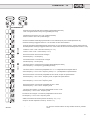
1.1
1.1
Conexionado
Connection Instructions
Un funcionamiento sin problemas y suguro del convertidor solo es
posible si se tienen en cuenta las siguentes puntualizaciones:
El incumplimiento de estas indicaciones puede provocar, en
determinados casos, defectuoso funcionamiento y fallos.
A safe and trouble-free operation of the inverter is warranted only
when the connection instructions listed below are observed:
If deviations from these specifications occur it can cause in
particular cases malfunctions and damages.
–
–
–
–
–
–
–
–
–
–
–
6
Instalación y conexionado del aparato únicamente por personal
cualificado.
Verificar cuidadosamente la instalación y utilización de material
eléctrico (VDE 0100).
Tomar las medidas de protección necesarias para personal y
maquinaria, según la normativa y las leyes vigentes.
El COMBIVERT ha sido concebido para un conexionado fijo.
No conectar o desconectar los cables de potencia y de mando
mientras el convertidor de frecuencia esté conectado a la red.
No efectuar medidas mientras el equipo esté en funcionamiento.
No confundir los cables de alimentación y los de motor.
Verificar la tensión de la red y la nominal del motor.
Separar los cables de mando y los de potencia (distancia
10cm).
Sólo conectar a los cables de mando elementos de conmutación
o de regulación (tales como relés, interruptores, potenciómetros)
previstos para baja tensión.
–
–
–
–
–
–
–
–
–
Installation and connection through authorized personnel
only.
Please observe the general installation regulations for the set
up and operation of electric plants (VDE 0100).
Protective measures for man and machine are to be carried
out in accordance to the local conditions and regulations.
KEB COMBIVERT is designed for a fixed connection.
Do not connect or disconnect the electric power cable and the
control cable as long as the frequency inverter is connected to
the mains.
Do not carry out any measurements at the inverter during
operation.
Do not confuse power line and motor line.
Please observe mains voltage and rated motor voltage.
Install control lines and power lines separately (10 cm
distance).
Connect control lines only to switching elements and adjustment
controls (relay, switch, potentiometer) that are suitable for low
voltage.
COMBIVERT F0
- Utilice cables de mando blindados y trenzados.Conectar únicamente los cables blindados al borne PE del convertidor.
– Utilice sólo cables de motor blindados y trenzados.Conecte
los cables blindados al borne PE, sobre la carcasa del motor.
– Asegúrese que el convertidor esté bien conectado a la toma de
tierra (conexionado estrella, evitar bucles de tierra, conexión
de toma de tierra lo mas corta posible a la red).
– Utilice cable blindado y trenzado para la conexión del módulo
de frenado.
–
–
–
–
Please use shielded / twisted control cables. Connect shield to
PE at inverter only.
Please use shielded / twisted motor lines. Connect shield to
PE and connect extensive shielding to motor housing.
Ensure good earthing of the frequency inverter. (star-shaped;
avoid earth circuits; shortest connection to main earth)
Use shielded / twisted cables for the connection of the braking
module.
All control lines are to be protected by additional
protective measurements (e.g. double insulation or
shielded; earthed and insulated), because according to VDE 0160 it involves voltages that are not
safely separated from the supply circuit as basic
insulation is used.
Todos los cables de mando deben ser blindados y de
doble aislamiento, según la norma VDE 0160.
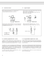
1.2
Corriente de fuga-Disyuntor diferencial (FI)
1.2
Fault Current - Protective Switch (FI)
Fault Current (FI) - Protective Switches may be
used only with certain restrictions in combination
with frequency inverters.
Los disyuntores diferenciales (FI) sólo pueden ser
utilizados con convertidores de frecuencia si se
tienen en cuenta ciertas restricciones.
–
Un convertidor de frecuencia trifásico puede impedir, en caso
de toma a tierra, el desenclavamiento del disyuntor diferenciala
causa de la componente de corriente continua de la corriente
diferencial.
Por esta razón y según la norma VDE 0160 el disyuntor diferencial no puede ser utilizado como único elemonto de
protección.Otras medidas, como la protección del espacio
o la neutralización (que no debe estar nunca a la salida del
convertidor) tambien deben ser tomadas.
–
In case of ground fault the equal portion in the fault current
may prevent the triggering of the FI-Protective Switch at
frequency inverters with 3 phase input voltage.
For that reason the FI-protective wiring as sole safety precaution is non-permissible according to VDE 0160. Further safety
precautions like i.e., protective spacing or neutralization are
required. The neutralization is not permitted at the output of
the frequency inverter.
–
El disyuntor diferencial debe corresponder al nuevo modelo
que dicta la norma DIN VDE 0664.
–
The FI-Protective Switch must correspond to the new design
in conformity with DIN VDE 0664.
–
La corriente de desenclavamiento debe ser de 200 mA o mas
para impedir así un desenclavamiento prematuro en la corriente
de fuga del convertidor.
–
The tripping current should be 200 mA or more in order to prevent
premature triggering by discharge currents of the inverter.
–
Excepción:
–
Exception:
En convertidores monofásicos (L,N) se permite la utilización
de un disyuntor diferencial como protección única, si éste
corresponde al último modelo adaptado a la norma DIN
VDE 0664 .
1.3
Protección del motor
When using frequency inverters with a single-phase input
voltage (L, N) the FI-Protective Switch must correspond to the
new design in conformity with DIN VDE 0664.
1.3
Motor Protection
Otras medidas de protección en caso de sobrecarga del motor
puede ser la utilización de una sonda PTC.
An extensive protection against overloading the motor by inverter
operation offers the PTC evaluation at the motor.
Los relés térmicos solo ofrecen una protección limitada y pueden, por lo tanto, provocar desenclavamientos erróneos en el
funcionamiento del convertidor.
Motor protective switch or motor protective relay offer only restricted protection and in individual cases they may cause fault
throwing by inverter operation.
7
1.4
Instrucciones de utilización
1.4
Para evitar un envejecimiento prematuro o posibles desperfectos lea atentamente las instrucciones siguentes.
–
–
–
–
–
La utilización de un dispositivo de desconexión entre la red
de alimentación y el convertidor de frecuencia permite aislar
al CONBIVERT del resto de la instalación.
Para garantizar un buen funcionamiento es necesrio evitar la
conmutación entre el motor y el convertidor, lo que podría
provocar la activación de las funciones de protección del
COMBIVERT.Si estas conmutaciones fuesen inprescindibles,
le rogamos que contacte Ud. con KEB para adaptar adecuadamente las medidas de protección.
En el caso de varios motores si se permite la conmutación,
siempre y cuando el convertidor no esté activado, aunque haya
un solo motor en funcionamiento.
El convertidor se debe dimensionar en función de las corrientes
de arranque de los motores . Pero si durante la conmutación
no funciona ningun motor, el mando de activación debe estar
abierto y la función Speed Search activada.Esta función se
inicia únicamente despues del cierre de los contactores del
motor.
Si el motor está en funcionamiento (debido a grandes masas
de inercia) cuando se le da una nueva orden de puesta en
marcha las funciones Speed Search y frenado DC deben estar
activadas. .
No se permiten frecuentes conmutaciones entre la red de
alimentación y el convertidor.
Utilice el COMBIVERT de KEB en las condiciones adecuadas
( para mas información ver capítulo 1.7.1).
1.5
Protección del convertidor contra parásitos
Las entradas de mando y de potencia del convertidor de frecuencia
están protegidas contra parásitos.
Una gran seguridad en el funcionamiento y protecciones complementarias se obtienen si se tienen
en cuenta las siguentes precauciones:
Operating Instructions
To avoid the premature ageing or destruction
of the KEB COMBIVERT observe the following
instructions.
–
–
–
–
–
Install a disconnecting switch between voltage supply and
frequency inverter to permit the independent switch off of the
KEB COMBIVERT.
With regard to single drives the switching between motor and
KEB COMBVERT should be avoided during operation as this
may activate the protective functions of the frequency inverter.
However, if switching must be done contact KEB to coordinate
the protective functions.
For multimotor drives the switching-on and switching-off is
permitted with control release is closed when at least 1 motor
is running during the switching process. The frequency inverter
must be layed out for the occurring starting currents.
But if no motor is running during the switching process between
motor and frequency inverter then the control release must
be open and the function Speed Search must be activated.
This function may be initiated only after the motor relays are
closed.
If the motor is still running at a restart (power on) of KEB COMBIVERT (e.g. large flywheel mass), the function Speed Search
or DC-Braking must be activated.
Frequent switching between mains and frequency inverter is
not permitted.
Operate KEB COMBIVERT under suitable conditions (refer to
1.7.1).
1.5
Noise Suppression of Frequency Inverter
The control and power inputs of the frequency inverter are generally
protected against parasitic noise.
An improved operational reliability of the unit and
additional protection against malfunctions is achieved by following measurements.
– Utilice un filtro de red cuando equipos de gran consumo
(Instalación de compensación,equipos de soldeo, hornos-HF,
etc) afectan a la red de alimentación.
– Instale circuitos RC u otros sobre los aparatos inductivos
(solenoides, contactores, electroimanes, etc) para absorber la
energia que se libera en la desconexión de estos equipos .
– Cablee como se describe en el capítulo 1.1 a fin de evitar
descargas inductivas.
– Use mains filter when the connection of large consumers
(compensation plants, welding equipment, HF-oven, electromagnetic holding fixture, etc.) affects the mains voltage.
– Protective wiring of inductive consumers (solenoid valves, relays, electromagnets) with RC elements or something alike to
absorb the energy set free at switch off.
– To avoid inductive and capacitive bunching of interference
pulses the wiring should be made as described under point
1.1.
Una pareja de cables trenzados protege de las descargas
inductivas (tensiones de interferencia), mientras que un cable
blindado protege contra las descargas capacitivas. Se obtiene
una correcta protección utilizando simultáneamente cables
blindados y trenzados y separando los cables de protección
de los de mando.
Paired-twisted cables protect against inductive-bunched interference voltage, shielding protects against capacitive-bunched
interference voltages. Optimum protection is provided by twisted and shielded cables and the separate laying of signal and
power lines.
8
COMBIVERT F0
1.6
Antiparasitaje de equipos eléctricos
1.6
Noise Suppression of Electric Plants
El convertidor de frecuencia COMBIVERT de KEB emite hondas electromagnéticas de alta frecuencia.Las perturbaciones
ocasionadas pueden ser reducidas de la forma que se indica a
continuación:
The frequency inverter KEB COMBIVERT transmits electromagnetic waves of high frequency. Following measurements reduce
the interference pulses that trouble electric plants in the vicinity
of the inverter:
–
–
–
–
–
–
Instale el convertidor en un armario metálico
Utilice cables de motor trenzados y blindados
El blindaje debe estar conectado al borne PE del convertidor
de frecuencia y sobre la carcasa del motor.En ningún caso
el blindaje debe ser utilizado como cable de masa del motor.
Para que la función de protección del blindaje sea eficaz debe
carecer de interrupciones y ser lo mas corta posible entre motor
y convertidor.
Realice una buena toma de tierra (cables de como mínimo 10
mm de sección).
Utilice filtros para suprimir las interferencias radio.
1.7
Implantación del COMBIVERT de KEB
–
installation of the frequency inverter inside a metal casing
shielded / twisted motor cables
The shield must be connected to PE of the frequency inverter
and to the housing of the motor (lay on the entire surface). The
shielding may not be used as protective earthing. The safe
function of the shielding is given only when it is uninterrupted
and when it begins as close as possible to the frequency inverter
ot the motor.
good earthing (metal-powder tape or 10 mm2 earth lead)
–
use of radio interference voltage filters
1.7
Installation of KEB COMBIVERT
1.7.1 Condiciones ambientales
1.7.1 Ambient Conditions
*
*
–
–
–
–
Valores máximos autorizados:
Temperatura de entrada del refrigerante
Temperatura ambiente de funcionamiento:
Temperatura de almacenamiento:
Temperatura de transporte:
-10 °C…+45 °C
-25 °C…+70 °C
-25 °C…+70 °C
Humedad relativa: máx. 95 %, sin condensación, (segun
apartado F de la norma DIN 40040)
Prohibida toda penetración de vapor de agua o líquido en el
interior del convertidor.
Evite la penetración de polvo en el convertidor.Si éste se
encuentra en el interior de un cofre estanque asegúrese que
tenga la ventilación adecuada.
Proteja al COMBIVERT contra gases y líquidos corrosivos.
–
Cuando es necesaria su implantación en un lugar deflagrante
es imprescindible utilizar un armario antideflagrante y respetar
la normativa en vigor.
–
–
–
Max. permissible limit values:
Coolant agent inlet temperature /
ambient temperature during operation:
Storage temperature:
Transport temperature:
-10 °C…+45 °C
-25 °C…+70 °C
-25 °C…+70 °C
Relative humidity: max. 95 %, without moisture condensation
(Identification character "F" DIN 40040)
No dampness or water is allowed to penetrate into KEB COMBIVERT.
Penetration of dust into the inverter must be avoided. When
installing KEB COMBIVERT in dust-proof enclosures care must
be taken to provide sufficient heat dissipation.
KEB COMBIVERT must be protected against gases and liquids.
For installation in explosion protected rooms, an explosionproof housing must be used. The regulations in force are to
be observed!
9
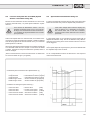
1.7.2 Instrucciones de instalación
1.7.2 Installation Instructions
El convertidor de frecuencia COMBIVERT de KEB cuenta con una
protección del tipo IP 20 y debe ser instalado en el interior de un
armario o un cofre. Debe además estar solidamente fijado y bien
conectado a tierra.
The frequency inverter KEB COMBIVERT has the protective system
IP 20 and is to be installed in a casing (control cabinet). This version
of KEB COMBIVERT must be firmly installed and earthed.
–
Respete las distancias mínimas (espacio libre suficiente)
arriba y abajo mín. 100 mm
en los lados mín. 50 mm
–
–
–
Instalación vertical
Prevea de antemano un enfriamiento suficiente
–
–
observe the minimum distance (free space)
above and below minimum 100 mm
at the sides minimum 50 mm (Chassis)
Rack units can be arranged side by side.
vertical installation,
provide sufficient cooling
Si en las proximidades del COMBIVERT de KEB se encuentran
otros equipos que producen campos eléctricos o magnéticos, o
perturbaciones sobre la red de alimentación, es recomendable
situarlos lo mas alejados posible y tomar todas las medidas a fin
de eliminar sus influencias.
If other consumers which produce electric or magnetic fields or
which effect the power supply are located in the vicinity of the
KEB COMBIVERT, they must be positioned as far away as possible
from the frequency inverter and steps must be taken to suppress
any interference.
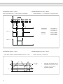
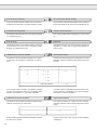
Cálculo de la superficie del armario
Calculation of control cabinet surface
A =
PV
ÐT • K
A =
[m ]
2
V =
ÐT
V =
[m /h]
3
A = Superficie del armario
[m2]
ÐT = Diferencia de temperatura
[K]
(Valor estandar = 20 K)
W
K = Coeficiente transferencia de calor [ m2 • K ]
W
(Valor estandar = 5 m²• K )
PV = Disipación calorífica
(ver tabla en pág. siguente)
V = Corriente de aire del ventilador
Para mas información, consulte
armarios de protección.
10
ÐT • K
[m2]
Rate of air flow at fan cooling
Corriente de aire del ventilador
3,1 • PV
PV
catálogos de fabricantes de
3.1 • PV
ÐT
[m3/h]
A = Control cabinet surface
ÐT = Temperature difference
(standard value = 20 K)
K = Heat transfer coefficient
(standard value = 5
W
m2 • K
[m2]
[K]
[
)
W
m2 • K
]
PV = Heat dissipation
(refer to table on next page)
V = Air flow rate of fan
For detailed information please refer to the catalogs of the control
cabinet manufacturers.
COMBIVERT F0
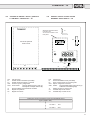
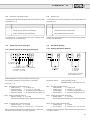
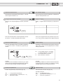
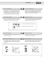
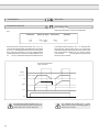
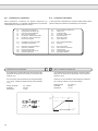
1.7.3 Implantación en armario
1.7.3 Control Cabinet Installation
100
100
50
KEB
COMBIVERT
F0
50
50
(Chassis)
100
Dirección de las aletas de
refrigeración
Direction of cooling fins
F0
F0
Rack Rack Rack
50
100
50 mm entre la parte delantera del convertidor (especialmente
delante de las ranuras de ventilación) y los elementos situados
frente al mismo.
50 mm minimum space between inverter front (in particular
ventilation slots) and elements positioned in front of it.
Salida de aire caliente
Warm air outlet
KEB
COMBIVERT
Entrada de aire frio
Cool air inlet
Disipación calorífica (PV) en carga nominal
Heat Dissipation (PV) at Nominal Load
Tamaño del convertidor
Inverter Size
07.F0 / 200 V
09.F0 / 200 V
09.F0 / 400 V
10.F0 / 400 V
12. F0 / 400 V
PV a 4 kHz
PV at 4 kHz
PV a 16 kHz
PV at 16 kHz
65 W
70 W
65 W
75 W
115 W
11
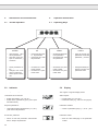
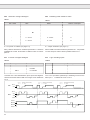
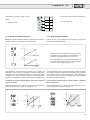
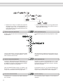
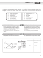
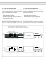
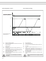
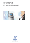
1.8
P
PN
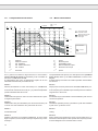
Comportamiento del motor
1.8
Condición
Condition
M
MN
10
20
30
40
50
60
Motor Performance
MK
> 1,3
M
70
80
90
100
f Hz]
1,6
Reserva de carga
Overload reserve
1,4
1,2
c
1,0
0,8
Según el tipo de motor
Dependent on the
motor type
d
MKN
>3
MN
b
0,6
0,4
a
1
Recomendación
Recommendation
MKN
>3
MN
MK > 1,6
M
MKN
>2
MN
0,2
300
P
PN
M
MK
MN
MKN
n
MKN
>2
MN
600
900
1200
1500
1800
Potencia
Potencia nominal
Par admisible
Par máximo del motor
Par nominal
Par nominal máximo
Velocidad
2100
2400
P
PN
M
MK
MN
MKN
n
2700
3000
n(1/min)
Power
Nominal power
Permissible torque
Motor breakdown torque
Nominal motor torque
nominal motor breakdown torque
Speed
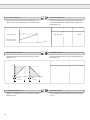
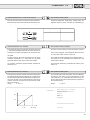
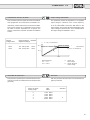
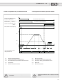
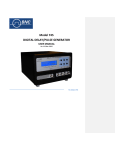
En la gráfica se muestra la carga límite de un motor trifásico
(motor estandar de 50 Hz) accionadoado por el convertidor de
frecuencia COMBIVERT de KEB.
El calentamiento del motor es ligeramente superior al de otro
alimentado directamente por tensión de red.
The permissible load capacity of a three-phase motor (standard
motor 50 Hz) driven by the KEB COMBIVERT is shown in the
diagram.
A higher heating of the motor as at mains operation must be taken
into account.
Curva 1:
Potencia de salida de un motor accionado por un COMBIVERT
de KEB(correspondiente a la curva característica del par c). Arriba
la frecuencia nominal del motor,el par y la potencia disponibles
quedan indicadas sobre las curvas.
Curve 1:
Output power of a three-phase motor with KEB COMBIVERT (corresponding to torque characteristic curve c). Above the nominal
motor frequency the available torque and the power are within the
range shown in the curves.
Curva a:
Característica del par de un motor con auto-ventilación de 4 polos
en régimen permanente.
Curve a:
Permissible torque characteristic of self-ventilated 4-pole motor at
continuous operation.
Curva b:
Característica del par intermitente (ciclo de servicio ED 25%) de
un motor con auto-ventilación de 4 polos.Ciclo de 10 min.
Curve b:
Intermittent operation (S3 duty cycle ED 25 %) with self-ventilated
4-pole motor. Cycle time 10 min.
Curva c:
Característica del par de salida para motor provisto de ventilación
forzada adacuada.
Curve c:
Permissible start-up torque for a motor with adequate forced
cooling.
Curva d:
Durante el arranque, en el régimen establecido, el motor puede
llegar a soportar 1,5 veces su par nominal por espacios muy cortos
de tiempo.
Curve d:
During starting and operation the motor may be loaded up to 1.5
times of its nominal torque for short periods. The frequency inverter
must be designed for the increased motor current.
12
COMBIVERT F0
2.
Características técnicas
2.
Technical Data
2.1
Características técnicas a 200/400 V
2.1
Technical Data 200/400 V Class
200 V
Tamaño / Size
400 V
07
09
09
10
11
12
Potencia de salida nominal
Rated output power
(kVA)
1,8
2,8
2,8
4,0
5,2
6,6
Corriente de salida nominal
Rated output current
(A)
4,5
7,0
4,1
5,8
7,5
9,5
0,75
1,5
1,5
2,2
Potencia nominal máxima,
motor 2-/4- polos*
Max. permissible nominal motor power,
2-/4-pole motor*
(kW)
Tensión de alimentación
Mains voltage
(V)
Tensión de salida
Output voltage
(V)
200 / 208 / 220 / 230 (3) / 240
180…264 ± 0 %
3 x 0 ... URed / UMains
1 ( Option 3 )
Fases
Line phases
3
Frecuencia red
Mains frequency
(Hz)
50 / 60 ± 2
Frecuencia de salida
Output frequency
(Hz)
0…408
Sobrecarga
Load capacity
151…200 % - 30 s
131…150 % - 2 min
111…130 % - 5 min
Fusibles red (1)
Mains fuse (1)
Sección de los cables
Wire cross section (2)
(1)
(2)
(3)
(2)
(A)
20
20
10
10
20
20
(mm2)
2,5
2,5
1,5
1,5
2,5
2,5
Fusibles de la red máximos admisibles
Sección mínima recomendada para la potencia nominal y para una
longitud máxima de 100 m de cable (cobre).
Valor subrayado = Tensión nominal
(1)
(2)
(3)
¡Antes de reemplazar los fusibles, desconecte el
convertidor de la red y espere aprox. 1 minuto!
*
380 / 400 (3) / 415 / 440 / 460
305…500 ± 0 %
Las características enumeradas corresponden a motores estandar de
2-/4- polos (la tensión de alimentación del motor debe corresponder
a la tensión máxima del COMBIVERT de KEB a 50/60 Hz).Para otra
combinación en número de polos, el convertidor debe estar dimensionado en función de la corriente nominal del motor
Para motores de alta frecuencia o motores especiales le rogamos
contacte con nuestros servicios técnicos.
ATENCION
Instalación a una altura máx. de 3000 m.
Por encima de los 1000 m de altura debe tenerse en cuenta
una reducción de la potencia del 1%.
Ejemplo: para una altitud de 1500 m = 95% Potencia nominal
Max. permissible mains fuse for the protection of the feeder cables
Recommended minimum wire cross section for rated power and a
cable length of upto 100 m (copper).
Underlined value = Rated voltage
Prior to replacing the fuses disconnect the inverter
from mains and wait for approx. 1 minute!
*
All performance data relate only to standard 2-/4-pole motors
(max. voltage of the motor must correspond to the max. voltage of
the KEB COMBIVERT at 50/60 Hz). For other pole combinations the
frequency inverter must be dimensioned for the corresponding rated
motor current.
Please contact KEB for information about special or medium-frequency
motors.
ATTENTION
Mounting altitude max. 3000 m above N.N.
A power reduction of 1% per 100 m must be taken into account
for mounting altitudes of 1000 m or more above N.N.
i.e. 1500mNN = 95% PNominal
13
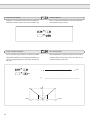
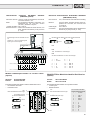
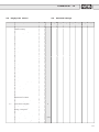
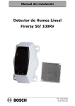
2.2
Dimensiones de la versión Chassis
2.2
Dimensions Chassis Version
C
D
B
A
Emplazamiento módulo de frenado
Insert for Braking Module
E
F
H
G
I
F
J
E
Tamaño
Size
A
B
C
D
E
F
G
H
07 / 09 1)
282
270
115
3
3
36
90
6,5
168
12,5
2,6
09 2) / 10 1)
282
270
155
3
3
36
90
6,5
168
12,5
3,6
1)
2)
14
Frecuencia de modulación 16 kHz
Frecuencia de modulación 4 kHz
1)
2)
4 kHz clock frequency
16 kHz clock frequency
I
J
Peso (kg)
Weight (kg)
COMBIVERT F0
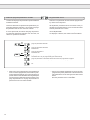
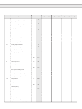
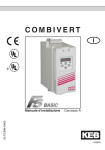
2.3
Dimensiones de la version rack
2.3
Dimensions Rack Version
G
J
D
C
I
H
F
B
E
A
m
0m
-7
50
X1
U
AN
V
TR
IEBS
TE
CH
W
NIK
!
ng
tuatorch ens it
A Konntdladeezen
!
e cht
a
be
on
ntiacitor
tte cap ime
A notcichearget
L1
N
dis
Pag. 88
+U
-U
DOW
FUN
1
2
3
4
5
6
7
8
9
10
11
12
13
14
15
16
17
18
19
20
21
22
23
C.
N
Opción
8
9
10
X2
ZK
ZK
X2
CHAR
GE
UP
ENTE
R
DOW
N
1
2
3
4
5
6
7
8
9
10
X3
11
12
13
14
FUNC
.
11
12
13
14
a partir del tamaño 10
from Size 10 upwards
Pag. 86
PA
PB
Option
Tamaño
Size
A
B
C
D
E
F
G
H
07 / 09
90
40
340
330
174
12,5
6
10 / 11 1) / 12 1)
90
40
340
330
238,5
12,5
6
1)
Frecuencia de modulación 4 kHz
1)
I
J
Peso (kg)
Weight (kg)
1,5
286
21
3
1,5
286
21
4
4 kHz clock frequency
15
3.
Conexionado
3.
Connection
3.1
Conexionado a 200/400 V Tamaños 07…12
3.1
Wiring Diagram 200/400 V-Class Size 07…12
LD1
+
–
– UzK
+ UzK
L L1
N L2
L3
PE
L (L1)
U
+
N (L2)
V
(L3)
M
3 ~
W
PE
PE
*
Charge
PA
PB
}
*) ¡Conexionado del blindaje a la carcasa del motor!
Lay extensive shield on the motor housing!
Circuito de mando
U
PE
V
W
L1
L1
¡Solamente para las versiones rack a partir del tamaño
10!
Only at rack units from size 10 upwards!
L2
N
L3
+
UzK UzK
GTR7
*
PE
L, N
L1, L2, L3
+UzK, -UzK
U, V, W
PE
PA, PB
16
*) ¡Conexionado del blindaje a la carcasa del motor!
Lay extensive shield on the motor housing!
M
3~
L
L1
Alimentación (monofásica)
(unicamente a 200 V)
Alimentación (trifásica)
(Opción a 200 V)
Circuito de corriente continua
(conexionado módulo de frenado)
Motor
Borne de tierra
Conexionadode la resistencia de frenado
PA = tensión continua (+)
PB = transistor de frenado GTR7
N
L2
L3
L, N
L1, L2, L3
+UzK, -UzK
U, V, W
PE
PA, PB
Mains Supply (1-phase)
(for 200 V class only)
Mains Supply (3-phase)
(for 200 V class Option)
DC Voltage Intermediate Circuit
(connection for braking module)
Motor
Protective Earth-Terminal
Connection for Braking Resistor
PA = d.c. voltage intermediate circuit +
PB = Chopper transistor GTR7
COMBIVERT F0
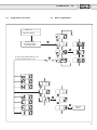
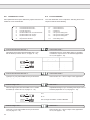
3.2
Circuito de mando / driver / potencia
a 200/400V Tamaños 07…12
3.2
F1
Control / Driver / Power Circuit
200/400 V Class Size 07…12
Situado en la parte frontal en
la versión rack.
At rack units located in the
front panel.
F2
CN1
1)
Circuito de potencia
Power Circuit
LD1
SW1
X1
LD1
F1
F2
CN1
SW1
J1
X1
X2
1)
X2
LED de carga
Fusible circuito intermedio (ver tabla)
Fusible circuito de mando 0,4 A lento
Conector opción y diagnóstico
Conmutador:
Relé de salida program. Out1 (A)
Mensaje de cualquier defecto (B)
Puente soldado para entrada de corriente
Regleta de potencia
Regleta de mando
Interface serie Opcional
LD1
F1
F2
CN1
SW1
J1
X1
X2
1)
A
B
J1
Charge LED
Fuse Intermediate Circuit (see table)
Fuse Control Circuit 0.4 A time-lag fuse
Option / Diagnosis Connector
Switch:
Programmable Relay Output Out1 (A)
Collective Fault Message (B)
Solder Jumper for current input
Terminal Strip Power Circuit
Terminal Strip Control Circuit
Serial Interface Option
Fusible para circuito intermedio/ Fuses for Intermediate Circuit
Type F (rápido / fast )
07 / 200 V
10 A
09 / 200 V
16 A
09 / 400 V
10 / 400 V
11 / 400 V
12 / 400 V
10 A
16 A
20 A
20 A
17
4.
Circuito de mando
4.
Control Circuit
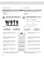
4.1
Conexionado regleta de bornes
4.1
Connection of Control Terminals
F
R
10
11
OU 0V +15VFRQ CRF REF COM ST RST FLA FLB FLC
T1
12 13 14 15 16 17 18 19 20 21 22 23
Alimentación externa / External Voltage Supply
RLA RLB RLC GND I1
1
2
3
4
5
I2
I3
6
7
RE
F1
8
RE
F2
9
P1
+
20...30VDC
3...10 kΩ
+
2. consigna
2nd set value
0...±10 VDC (1)
0...+10 VDC (2)
+
0...20 mA DC (3)
4...20 mA DC (4)
+
Alimentación interna / Internal Voltage Supply
RLA RLB RLC GND I1
1
2
3
4
5
I2
I3
6
7
RE
F1
8
RE
F2
9
F
R
10
11
OU 0V +15VFRQ CRF REF COM ST RST FLA FLB FLC
T1
12 13 14 15 16 17 18 19 20 21 22 23
P1
Activación
(1)
(2)
(3)
(4)
Poti P1
0...±10 VDC
0...+10 VDC
0...20 mADC
4...20 mADC
Ajuste de parámetros
Parameter Setting
o.13 H.0
H.1
3 (2)
4
3 (2)
3 (2)
3 (2)
0
3
0
1
2
0
0
2
2
2
3...10 kΩ
+
2. consigna
2nd set value
+
0...+10 VDC (2)
+
18
0...±10 VDC (1)
0...20 mA DC (3)
4...20 mA DC (4)
COMBIVERT F0
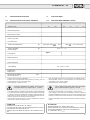
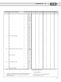
4.2
Descripción regleta de mando X2
Borne
Terminal
4.2
Nombre
Name
Occupancy of Control Terminal Strip X2
Función
Function
1
RLA
2
RLB
3
RLC
4
GND
5
I1
entradas programables, PNP tensión de 13...30 V +/- 0% no pulsatorias
6
I2
programmable inputs, PNP not potential-separarated, 13...30 V +/- 0% smoothed
7
I3
8
REF1
consigna analógica ±10 V adicionables a REF
analog set-point value setting ±10 V acts adding to REF
9
REF2
consigna analógica
analog set-point value setting
10
F
sentido horario/Forward
11
R
sentido antihorario/Reverse
12
OUT1
salida programable colector abierto máx.. 30 V/ 30 mA
programmable Open-Collector Output max.. 30 V/ 30 mA
13
0V
masa para mando digital externo / earth for external digital wiring
14
+15 V
salida +15 V máx. 30 mA / +15 V output max. 30 mA
15
FRQ
señal de salida analógica 0..10 V, 0...1 mA, U ~ frecuencia o U ~ carga
analog output signal 0...10 V, 0...1 mA, U ~ frequency or U ~ load
16
CRF
tensión de referencia +10 V para potenciómetro de consigna máx.. 6 mA
+10 V reference voltage for set value potentiometer max. 6 mA
17
REF
entada + de la consigna anal.
relé de salida programable 2
programmable relay output 2
conexión de blindage de mando y consigna / Connection for shield
analog set-point value setting
18
COM
19
ST
activación convertidor
Control release
20
RST
reset
21
FLA
22
FLB
23
FLC
0...10 V, 0…20 mA, 4…20 mA
0...10 V, 0…20 mA, 4…20 mA
PNP alimentada:
PNP not potential-separated:
13…30 V ±0 % no pulsatoria / smoothed
0…10 V o ±10 V,
0…20 mA y 4...20 mA ajustable por puentes soldados
0…10 V or ± 10 V,
0…20 mA and 4...20 mA adjustable by solder jumpers
masa de la consigna analógica / earth for external analog wiring
PNP alimentada:
PNP not potential-separated:
13...30 V ±0 % no pulsatoria
relé de salida programable 1
programmable relay output 1
19
5.
Introducción al funcionamiento
5.
Operation Introduction
5.1
Teclado operativo
5.1
Operating Keys
ENTER
–
–
–
–
5.2
DOWN FUNCT
UP
ENTER
–
UP
memorización valor
de los parámetros
pasa del menú principal al submenú y
viceversa
–
stores parameter value
changes from main
menu to sub menu
status report is deferred
–
–
–
DOWN
incremento del número de parámetro
incremento del valor
del parámetro.
–
increases the parameter number
increases the parameter value
–
Indicador
–
–
FUNCT
decremento del número de parámetro
decremento del valor
del parámetro.
–
pasa del número de
parámetro al valor del
parámetro y viceversa
decreases the parameter number
decreases the parameter value
–
changes between parameter number and
parameter value
5.2
Display
Los 3 digitos de 7 segmentos indican:
The 3-figure 7 segment display shows
La situación de los estados
Status reports
–
–
–
–
Estado del variador (LS, noP, etc.)
Estado de los parámetros (por ej. "FAU" para
entrada errónea)
Inverter status (LS, noP etc.)
Parameter status (e.g. "FAu" for wrong input)
El tipo de parámetros
Parameter numbers
–
–
compuesto de grupo de parámetro (r, o, H, etc.)
y del número de parámetro
consist of parameter group (r, o, H etc. ) and
the consecutive parameter number
El valor del parámetro
Parameter values
–
–
20
indica el valor del parámetro seleccionado
dentro del tipo de parámetro
show the value belonging to the parameter
number
COMBIVERT F0
5.3
Organización del menú
5.3
Menu Organization
Power on
Indicador / Display
r.29
DOWN
Estado/ Status
Valor del parámetro
Parameter Value
FUNCT
UP
UP
FUNCT
El salto queda determinado por r.22.
The jump is determined by r.22.
UP
DOWN
ENTER
���
UP
UP
DOWN
FUNCT
DOWN
ENTER
Memoria
Store
21
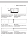
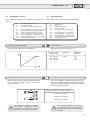
5.4
Activación y selección del sentido de giro
4
10 11
F
5.4
Control Release and Setting of Rotational
Direction
12 13 14 15 16 17 18 19 20
R
ST RST
Cuando el borne 19 (ST) est á conectado al borne 14 (+15 V),
la salida del KEB COMBIVERT está activada. La preselección
del sentido de giro viene dada por el teclado, por bus o por los
bornes 10 y 11 (en función de o.13). Si los dos sentidos de giro
son seleccionados simultaneamente, F tiene prioridad.
When terminal 19 (ST) is connected with terminal 14 (+15 V) the
output of KEB COMBIVERT F0 is released. The presetting of the
rotational direction is done by keyboard, bus or the terminals 10
and 11 (depends on o.13). If both rotational direction are selected
simultaneously then F has priority.
o.13 Tipo entrada de datos
o.13 Input Source
Activation of set value / direction of rotation
Consigna / sentido de giro
o.13
0
1
2
3
4
5
r.20
Consigna
Sentido de rotación
Teclado / Bus
Teclado / Bus
Regleta de bornes
Regleta de bornes
Regleta de bornes(+/-)
Bus (+/-)
Teclado / Bus
Regleta de bornes
Teclado / Bus
Regleta de bornes
(dependiente consigna)
(dependiente consigna)
Selección del sentido de giro
La preselección del sentido de giro por teclado o por bus únicamente es posible si la elección se ha realizado por medio
del parámetro o.13 (0 o 2). En caso contrario,el valor carece de
significado.
r.20
LS
F
R
Función
sin sentido de giro
giro en sentido horario
giro en sentido anti-horario
o.13
0
1
2
3
4
5
r.20
Set Value
Rotational Direction
Keyboard / Bus
Keyboard / Bus
Terminal strip
Terminal strip
Terminal strip (±Signal)
Bus (±Signal)
Keyboard / Bus
Terminal strip
Keyboard / Bus
Terminal strip
(depends on set value)
(depends on set value)
Rotation Setting
The presetting of the rotational direction by keyboard or bus protocol
is only possible when admitted in the parameter o.13. Otherwise
this value is without significance.
r.20
LS
F
R
Function
no rotational direction
rotational direction forward
rotational direction reverse
Doble función de la tecla ENTER
Double-ENTER-Function
La entrada de datos se integra pulsando la tecla ENTER (el
punto situado a la derecha del 3º dígito se apaga ).Al pulsar ENTER por segunda vez, el dato se memoriza en la EEPROM (doble
asignación de un parámetro por ENTER, ver anexo B).
The input is integrated by pressing the ENTER key (the point on
the 3rd LED goes out). Pressing the ENTER key again stores the
input in the EEPROM (Double-ENTER-Parameter see Annex B).
22
COMBIVERT F0
C.2
Restricción del sentido de giro
La preselección del sentido de giro puede venir limitada por medio
del parámetro C.2.
C.2
C.2
The presetting of the rotational direction can be restricted by the
parameter C.2.
Función
Fr
F–
–r
––
Rotation Lock
C.2
no hay sentido de giro restringido
sentido de giro anti-horario restringido
sentido de giro horario restringido
ambos sentidos de giro restringidos
Function
Fr
F–
–r
––
none of the rotational directions locked
rotational direction reverse locked
rotational direction forward locked
both rotational directions locked
La selección de un sentido de giro hace que el variador de frecuencia vaya a Low Speed (LS).
Selecting a locked rotational direction causes the frequency inverter
to trip to Low Speed (LS).
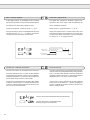
5.5
5.5
Selección de la consigna
5.5.1 Selección de la consigna analógica
4
8
0...+10 V DC
Ri = 56 kΩ
+
9
16 17 18
Set Value Setting
5.5.1 Analog Set Value Setting
4
18
17
4
18
17
+
+
0...20 mADC, Ri = 250 Ω
4...20 mADC, Ri = 250 Ω
0...10 VDC, Ri = 4,4 kΩ
3...10 kΩ,/0,5W
0...+10 V DC
Ri = 56 kΩ
+
0...20 mA DC
4...20 mA DC
Ri = 500 Ω
(puente soldado J1cerrado)
(close solder jumper J1)
KEB COMBIVERT F0 está programado de tal forma que:
las consignas analógicas corresponden a la posición0
mientras que las consignas digitales corresponden a las
posici ones 1 - 3.
For KEB COMBIVERT F0 the presetting of the setpoint value is
adjusted as follows:
analog presetting in set 0
digital presetting in parameter sets 1-3.
REF: entrada de la consigna (borne 17)
– Potenciómetro
3…10 kΩ/ 0,5 W
– Señal del tension
0…10 V DC, 0…±10 V DC
– Señal de corriente 0…20 mA DC (puente soldado J1)
– Señal de corriente 4…20 mA DC (puente soldado J1)
REF: set value input (terminal 17)
– Potentiometer
3…10 kΩ/ 0,5 W
– Voltage signal
0…10 V DC, 0…±10 V DC
– Current signal
0…20 mA DC (solder jumper J1)
– Current signal
4…20 mA DC (solder jumper J1)
REF1: consigna adicional (borne 8)
– Señal de tensión 0…±10 V DC
Esta señal de tensión se suma algebraicamente al valor
de la consigna de entrada REF.
REF1: adding set value input (terminal 8)
– Voltage signal
0…±10 V DC
The voltage signal is added sign-correct to the set value
input REF.
REF2: 2. entrada de la consigna (borne 9)
– Señal de tensión 0…10 V DC
– Señal de corriente 0…20 mA V DC, 4…20 mA V DC
REF2: 2nd set value input (terminal 9)
– Voltage signal
0…10 V DC
– Current signal
0…20 mA V DC, 4…20 mA V DC
El tipo de señal de entrada viene determinado por el parámetro
H.0 de acuerdo con la tabla 1.(ver pág. siguiente)
The type of the input signal is determined with the parameter H.0
according to table 1.
23
H.0
Selección consigna analógica
H.0
Tabla 1
Presetting mode reference value
Table 1
Valor / Value
0
1
2
3
4
5
6
7
8
9
10
11
REF
REF2
0…10 V
0…10 V
0…10 V
± 10 V
± 10 V
± 10 V
0…20 mA
0…20 mA
0…20 mA
4…20 mA
4…20 mA
4…20 mA
0…10 V
0…20 mA
4…20 mA
0…10 V
0…20 mA
4…20 mA
0…10 V
0…20 mA
4…20 mA
0…10 V
0…20 mA
4…20 mA
}
o.13 = "4"
Puente J1/Jumper 1
–
–
–
–
–
–
X
X
X
X
X
X
X = con puente J1 soldado (ver página 17)
X = Jumper soldered in (see page 17)
REF y REF2 se seleccionan mediante el parámetro H.1. Existe la
posibilidad de invertir las entradas. La tabla 2 indica los valores
para H.1.
REF and REF2 are selected with the parameter H.1. It is possible
to invert the inputs. Table 2 shows possible values for H.1.
H.1
H.1
Inversión consigna analógica
Tabla 2
Logic of analog inputs
Table 2
Valor
Consigna activada
0
1
2
3
REF/REF1
REF/REF1
REF2
REF2
Value
Lógica
0
1
2
3
no invertida
invertida
no invertida
invertida
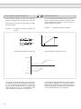
La tensión ±10 V de la entrada REF1 (borne 8) se suma algebraicamente a la tensión dada en REF. Se consigue f máx. añadiendo
±10 V.
����
���
���
�����
o.13 =
H.0 =
Regleta / Terminal Strip
0 ... 10 V
o.13 =
H.0 =
Active Set Value Input
REF
REF
REF2
REF2
Logic
not inverted
inverted
not inverted
inverted
The ±10 V input REF1 (terminal 8) is added sign-correct to the
REF input. fmax is attained at a sum of ±10 V.
Regleta / Terminal Strip
0 ... ±10 V
o.13 =
H.0 =
±Regleta/±Terminal Strip
0 ... ±10 V
����
���
����
�����
����
������
������
����
El sentido de giro depende de la selección realizada sobre la
regleta.
24
El sentido de giro depende de la polaridad de la consigna.
COMBIVERT F0
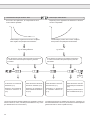
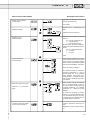
5.5.2 Selección de la consigna digital
5.5.2 Digital Set Value Setting
1.
1.
Teclado
Keyboard
Para ajustar el valor de la consigna por medio del teclado, el parámetro o.13 (modos de mando) debe estar programado en 0 ó 1.
En los grupos 1-3 el tipo de entrada de datos se realiza mediante
el teclado.
For the digital frequency setting by keyboard the parameter o.13
(input source) must be adjusted for set value setting by keyboard
(o.13 = 0 or 1). In the parameter sets 1-3 the setpoint value is
preset by keyboard.
El parámetro r.19 (consigna de velocidad) se ajusta al valor deseado
y puede memorizarse pulsando la tecla "ENTER".
The parameter r.19 (reference setting) is adjusted to the desired
frequency and can be stored non-volatile by pressing "ENTER".
UP
FUNCT
DOWN
ENTER
2.
Memoria
Store
r.19
Rango
Resolución
r.19
Setting Range
fconsigna
0...408 Hz
0,1 Hz
fset
0408 Hz
Protocolo Bus (opción)
2.
Resolution
0.1 Hz
Bus Protocol (Option)
Para preseleccionar el valor de consigna mediante el interface
serie, el parámetro 0.13 (modos de mando) debe ser programado
con los valores "0", "1" ó "5".
In order to preset the set value by serial interface the parameter
o.13 (input source) must be programmed with the value "0", "1"
or "5".
3.
3.
Posición de parámetros
Se pueden programar y activar 7 juegos diferentes de parámetros
(0 a 6) por medio de las entradas I1 hasta I3, por teclado o por bus
(en función del parámètro H.8). Todos los parámetros pueden ser
programados desde el juego de parámetros 0 y únicamente aquellos
especificados en la página 26, desde los juegos de parámetros
1-6.Los juegos de parámetros pueden ser activados durante el
funcionamiento para permitir, por ejemplo, un funcionamiento
en multi-consigna.
Parameter Set
Seven different parameter sets (0...6) may be programmed and
activated via inputs I1 to I3, the keyboard or the bus (depending
on H.8). All parameters can be programmed in the parameter set
0 whereas only the parameters especially listed on page 26 can
be programmed in parameter sets 1...6. The parameter sets are
selectable On-Line which permits for example Multi-Step-Speed.
25
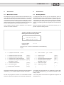
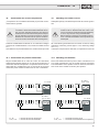
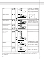
5.6
5.6
Entradas programables I1…I3
By means of the programmable inputs six additional parameter
sets and different additional functions of the frequency inverter
can be activated. The inputs can be activated either coded (e.g.
for PLC) or uncoded.
Por medio de las entradas programables se pueden activar seis
juegos de parámetros así como diferentes funciones del variador.
Las entradas pueden activarse de forma codificada, o bien, decodificada (por ejemplo, mediante un autómata programable).
GND I1
4
5
I2
I3
+15V
6
7
14
Mando en PNP sin separación galvánica
13...30 V ±0 % filtrada.
Parámetos por defecto
I1
=
Grupo 1
I2
=
Grupo 2
I1 + I2 =
Grupo 3
I3
=
Frenado DC
Presetting:
I1
=
I2
=
I1 + I2 =
I3
=
PNP activation not potential-separated
13...30 V ±0 % smoothed.
En los seis juegos de parámetros adicionales se pueden programar
los siguentes parámetros.
Parámetros - r
r.19
r.20
Parámetros - o
todos / all
Parámetros - P
todos / all
Parámetros - H
H.0
H.1
H.3
H.4
H.5
H.9
H.10
H.11
Parámetros - L
todos / all
Parámetros - d
todos / all
Parámetros - C
C.0
C.2
C.6
C.7
C.8
C.10
C.14
C.15
Set 1
Set 2
Set 3
DC-Braking
In the six additional parameter sets the following parameters can
be programmed.
consigna frecuencia / reference setting
selección del sentido de giro / rotation setting
selección consigna analógica / presetting mode reference value
inversión consigna analógica / logic of analog inputs
inversión salida lógica / output logic
función salida Out 1 / out1-function
función salida Out 2 / out2-function
función salida analógica / analog output function
offset salida analógica / analog output offset
ganancia salida analógica / analog output gain
límite de la frecuencia máxima / limit of maximum reference A
restricción sentido de giro / rotation loack
nivel automático de frenedo DC / DC-level-auto-set
modo activación de frenado DC / DC-braking mode
frecuencia portadora / carrier frequency
estabilización tensión de salida / output voltage stabilization
offset de la consigna analógica / zero clamp speed
selección de la modulación / select mode of modulation
Ademas, las funciones de frenado DC o de Ahorro energético se
pueden activar por medio de la entrada I3 .
26
Programmable Inputs I1…I3
In addition to it DC-Braking or Energy-Saving Function can be
activated by way of input I3.
COMBIVERT F0
La función de las entradas I1 hasta I3 viene determinada por el
parámetro H8 (entradas lógicas). Las tablas que figuran a continuación no son aplicables a las entradas invertidas.
FUNCT
DOWN
I3
I2
I1
Juego de parámetros / Set
*
X
X
0
I3
I2
I1
Juego de parámetros / Set
*
X
X
0…3 por bus / by bus
Entrada codificada
Input-coded
Código binario
Binary coded
UP
The function of the inputs I1…I3 is determined in the parameter
H.8 (in-function). The following tables are not applicable for inverted inputs.
I3
*
*
*
*
I2
0
0
1
1
I1
0
1
0
1
Juego de parámetros / Set
0
1
2
3
I3
0
0
0
0
1
1
1
1
I2
0
0
1
1
0
0
1
1
I1
0
1
0
1
0
1
0
1
Juego de parámetros / Set
0
1
2
3
4
5
6
Juego errores / Set Error
Entrada codificada
Input-coded
Código binario
Binary coded
Entrada codificada impulsada
Input-coded, edge-triggered
Código binario,
por impulsos
Binary coded,
edge-triggered
I3
R
0
0
0
I2
X
0
1
1
1
I1 Juego de parámetros / Set
X
0
1
1
1
0
2
1
1
3
I3
I2
I1
Juego de parámetros / Set
*
X
X
0...3 por teclado /
by keyboard (r.23)
I3
I2
I1
Juego de parámetros / Set
*
*
*
0
X
1
0
1
0
I3
0
X
X
1
I2
0
X
1
0
I1
0
1
0
0
I3
I2
I1
R
0
0
X X
X 1
1
1
1 0
0
1
2
Juego de parámetros / Set
0
1
2
3
Juegoo de parámetros / Set
0
1
2
(ver / see B1)
(ver / see B2)
X
0
1
*
R
1
–
–
–
–
–
–
sin función
no activado
activado
función adicional (frenado DC o Ahorro energético)
reset al juego de parámetros 0 (prioritario)
cambio por impulsión positiva
X
0
1
*
R
1
–
–
–
–
–
–
without function
terminal open
terminal closed
additional function (DC-Braking or Energy-Saving function)
Reset to set 0 (Priority)
switches at positive edge
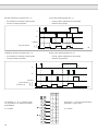
27
Entrada codificada por impulsos (H.8 = 7)
Input-coded, edge-triggered (H.8 = 7)
–
–
–
–
las entradas son activadas a cada impulso
el reset es siempre prioritario
at every positive edge all inputs are queried
reset has always priority
I1
I2
I3 Reset
Juego de parámetros
Parameter set
{
2
1
0
B1
Codificación binaria por impulsos (H.8 = 8)
Binary coded, edge-triggered (H.8 = 8)
–
–
–
–
las entradas son activadas a cada impulso
el reset es siempre prioritario
at every positive edge all inputs are queried
reset has always priority
I1
I2
I3 Reset
Juego de parámetros
Parameter set
{
3
2
1
0
B2
FUNCT
Las entradas I1…I3 se pueden invertir
con el parámetro H.7 (lógica de entradas
programables).
X = invertida
DOWN
UP
28
I3
I2
I1
-
-
-
-
-
X
-
X
-
-
X
X
X
-
-
X
-
X
X
X
-
X
X X
The inputs I1…I3 can be inverted with the
parameter H.7 (input logic).
X = inverted
COMBIVERT F0
5.6.1 Funciones adicionales
5.6.1 Additional Functions
Para activar las funciones de frenado DC y ahorro energético por
medio de la entrada I3, al parámetro H.8 se le debe asignar un
valor menor o igual que 4.
Esta entrada tambien guarda relación con los parámetros C.7
(modo de activació del frenado DC) ó P.11 (modo de ahorro
energético).
In order to activate DC-braking or energy-saving function over the
input I3 the parameter H.8 must be programmed with a value 4.
Los parámetros C.7, P.11 y H.8 mantienen una relación de dependencia con el fin de evitar posibles errores de programación.
The parameters C.7, P.11 and H.8 are locked against each other
to exclude any error programming.
Ejemplo: Dado que I3 está programada para el frenado DC, la
función ahorro energético por medio de I3 y los valores
que van de 5 hasta 8 en el parámetro H.8 están restringidos .
Example: Because I3 is programmed for DC-Braking, the energy-saving function by way of I3 and the values 5...8 in
parameter H.8 are locked.
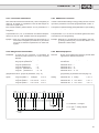
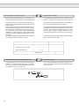
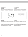
5.6.2 Rango multi-velocidades
5.6.2 Multi-Step-Speed
Posibilidad:
Demand:
By way of two switches the frequency inverter shall
approach four different frequencies.
Solution:
The inputs I1 and I2 are programmed for parameter
set selection.
The input is occupied accordingly in the parameters C.7 (DC-braking
mode) or P.11 (energy-saving function).
A través de dos conectores, el convertidor de
frecuencia puede funcionar con cuatro consignas
distintas..
Las entradas I1 y I2 se programan para la selección
del grupo de parámetros.
Solución:
Juego de parámetros 0
Juego de parámetros 1
Juego de parámetros 2
Juego de parámetros 3
=
=
=
=
–
I1
I2
I1 + I2
Parameter set 0
Parameter set 1
Parameter set 2
Parameter set 3
(programación de los grupos de parámetros, ver p. 71)
Ajuste:
Juego de parám. 0
Juego de parám. 1
Juego de parám. 2
Juego de parám. 3
GND
4
I1
5
analógico
r.19 = 5Hz
r.19 = 50 Hz
r.19 = 70 Hz
–
I1
I2
I1 + I2
(programming of parameter sets see page 71)
o.13 = 3
o.13 = 1
o.13 = 1
o.13 = 1
I2
I3
F
R
+15V
6
7
10
11
14
Frenado DC
=
=
=
=
Setting:
16
17
18
Parameter set
Parameter set
Parametre set
Parameter set
ST
RST
19
20
0
1
2
3
analog
r.19 = 5 Hz
r.19 = 50 Hz
r.19 = 70 Hz
o.13 = 3
o.13 = 1
o.13 = 1
o.13 = 1
I1…I3 abiertos -> consigna
analógica
I1…I3 open -> analog setpoint
value
5Hz 50Hz
70 Hz
29
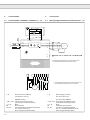
5.7
Señales de salida
5.7
Relé de salida programable Out 2 (-> Parámetro H.5)
Programmable Relay Output Out2 (-> par. H.5)
Signal Outputs
SW1 en posición. A: Relé salida progr. Out1 (A) (-> Par. H.4)
SW1 en posición. B: Relé Defecto
SW1 in posit. A: Progr. relay output Out1 (A) (-> par. H.4)
SW1 in posit. B: Fault Relay
SW1
1
2
3
4
4
21 22 23
250 V AC / 0,2 A
30 V DC / 1,0 A
Señal de salida analógica program. (U ~Frecuencia/Utilización)
Programmable analog Output Signal (U ~Frequency/Utilization)
(-> Parámetros H.9, H.10, H.11)
A
B
250 V AC / 0,2 A
30 V DC / 1,0 A
Salida colector abierto programable Out1 (-> Par. H.4)
Programmable Open Collector Output Out1 (-> par. H.4)
+15V
4
0…10 VDC
Ri > 56 kΩ constante
0…1 mADC
Ri < 5 kΩconstante
Offset: max. ±50 mV
15
18
+
12
14
max.30 V / 30 mA
5.7.1 Salidas programables Out 1 / Out 2
5.7.1 Programmable Outputs Out1 / Out2
La salida del colector abierto (borne 12) figura siempre en la
salida Out 1. Si el conmutador SW1 está en posición A, la salida
relé (bornes 21…23) funciona al mismo tiempo que Out 1. En
posición B, esta salida relé está separada de Out 1 y funciona
como relé de fallo.
The open-collector output (terminal 12) is always activated as Out1.
If the DIP-Switch SW1 is in position A the relay outputs (terminal
21…23) are also switched by Out1. In position B the output operates as fault relay.
Las salidas Out 1 y Out 2 se programan independientemente la
una de la otra en función de los parámetros H.4 y H.5. Mediante
un cableado externo y una programación adecuada, es posible
tambien activar las entradas l1... I3 con estos relés.Así, por
ejemplo, se puede utilizar la detección del valor de la frecuencia
de un juego de parámetros para activar otros.
The outputs Out1 and Out2 are programmable independent of each
other by means of the parameters H.4 and H.5. Through external
wiring the relay outputs can be used for the switching of the inputs
I1…I3. By corresponding programming it is possible to switch
to another parameter set e.g. in dependence on the frequency.
Los valores que pueden adoptar los parámetros H.4 y H.5 se
indican en la tabla de la página siguiente.
The possible parameter values for H.4 and H.5 are listed in the
table on the following page.
30
COMBIVERT F0
Out 1
Out 2
FUNCT
Detección de cualquier fallo del convertidor (preajustada para Out1)
Fault / run signal reacts to every error (presetting for Out1)
No detecta la función de error "UP" (caída de tensión)
Does not react to error "UP" (undervoltage)
Se activa si detecta sobrecarga (transcurrido un 10% del tiempo de paro=cuando aparace E.OL)
Overload warning is triggered when 10 % of the switch-off time are exceeded
Se activa si detecta sobrecalentamiento (transcurrido un 10% del tiempo de paro= cuando aparece E.OH)
Overtemperature warning is triggered when 10% of the switch-off time are exceeded (switch-off time=1 min)
Corriente > Out1 / Out2 - Nivel de corriente (L.2 / L.3)
Current > Out1 / Out2 - current level (L.2 /L.3)
DOWN
Frecuencia actual< Frecuencia de consigna
Actual frequency < set frequency
Frecuencia actual > Frecuencia de consigna
Actual frequency > set frequency
UP
Frecuencia actual = Frecuencia de consigna (preajustada para Out2)
Actual frequency = set frequency (presetting for Out2)
Frecuencia actual < Frecuencia preajustada en L.0 o L.1 independiente de Speed Search.
Actual frequency < Out1 / Out2 - frequency level (L.0 / L.1) independent of Speed Search.
Frecuencia actual < Frecuencia preajustada en Out1 Out2, excepto en Speed Search
Actual frequency < Out1 / Out2 - frequency level, exception at Speed Search.
Frecuencia actual > Frecuencia preajustada en Out1 / Out2
Actual frequency > Out1 / Out2 - frequency level
Frecuencia actual = Frecuencia preajustada en Out1 / Out2
Actual frequency = Out1 / Out2 - frequency level
Frecuencia de consigna < Frecuencia preajustada en Out1 / Out2
Set frequency < Out1 / Out2 - frequency level
Frecuencia de consigna > Frecuencia preajustada en Out1 /Out2
Set frequency > Out1 / Out2 - frequency level
Salida, activada transcurrido el periodo del timer (L.16 y L.17).
Output is set after expiration of timer (L.16 and L.17).
Para memorizar los valores asignados, pulsar dos veces la tecla
"ENTER".
To store the entered values the key ENTER must be pressed
twice.
31
Conmutación de Out 1 y Out 2
Switching behaviour of Out 1 / Out 2
-para frecuencia actual < ó > f de consigna ó f preajustada
–
at actual frequency < or > set frequency or frequency level
factual
1)
fconsigna
1)
t
1)
Histéresis de
conmutación
0,5 Hz Mode 1-f
1,0 Hz Mode 2-f
2,0 Hz Mode 4-f
1)
Switching
hysteresis
0.5 Hz 1-f Mode
1.0 Hz 2-f Mode
2.0 Hz 4-f Mode
Out 1, 2
factual < fconsigna
t
Out 1, 2
factual > fconsigna
t
Conmutación de Out 1 y Out 2
Switching behaviour of Out 1 / Out 2
–
–
para carga > Nivel de corriente preajustado en Out 1 / Out 2
at load > Out1/Out2 - current level
I
I=+5%
L
t
Out 1/2
t
32
IL:
Nivel ajus. de corriente (L.2/L.3)
Adjustable current level (L.2/L.3)
∆I:
Histéresis de conmutación
Switching hysteresis
COMBIVERT F0
Las salidas se pueden invertir con la ayuda del parámetro H.3 (inversión salida
lógica).
Out 2 Out 1
The outputs can be inverted with the parameter H.3 (output logic).
FUNCT
X = Salida invertida
-
-
-
X
X
-
X
X
X = output inverted
5.7.2 Señal de salida analógica
5.7.2 Analog Output Signal
Mediante la señal de salida analógica, la frecuencia o la corriente
With the analog output signal the actual frequency or the current
load can be shown alternatively.
actuales pueden ser visualizadas alternativamente.
U
10 V
FUNCT
408 Hz
U
f
10 V
Las curvas corresponden a un instrumento de medida provisto de una resistencia interna de Ri = 56
kΩ. Mientras que la salida no está cargada (Ri -> ×)
la tensión es aproximadamente de unos 11 V.
The curves apply to a constant internal resistance of
the measuring instrument of Ri = 56 kΩ. During idle
run (Ri -> ×) the voltage is approx. 11 V.
I
200 %
Una adaptación universal para la conexión de un aparato de
medida así como el rango de medida son posibles mediante los
parámetros H.10 (offset salida analógica) y H.11 (ganancia salida
analógica). Una vez introducido el password, estos parámetros
pueden ser modificados mediante visualización instantánea de
sus ajustes sobre el mismo aparato de medida.
El aparato de medida utilizado deberá tener una resistencia
interna constante.
A universal adaption to the connected measuring device as well as
the measuring range is possible with the parameters H.10 (analog
output offset) and H.11 (analog output gain). After entering the
password the parameters can be changed online thus permitting
the adjustment in direct dialog.
El ajuste estandar es de 11 V para la frecuencia máxima del rango
de frecuencia (mode-f) y salida no cargada (Ri -> ×).
The standard setting is 11 V for the maximum frequency of a frequency range (f-Mode) and idle run (Ri -> ×).
The connected measuring device must produce a constant
internal resistance.
U
U
11 V
11 V
FUNCT
FUNCT
50 %
%
5,5 V
%
0V
4.00
5,5 V
0%
1.00
0.00
0V
0
0
204 Hz
100 %
408 Hz
200 %
0
0
204 Hz
100 %
408 Hz
200 %
33
5.8
Informe de los estados
5.8
Status Reports
Existen dos tipos de mensaje acerca del estado:
It is to be differentiated between two status messages:
a) Informe del estado del convertidor
a) Inverter status report
No operacional, no está activado
No operation, no control release
Bloqueo de la etapa de potencia
Base Block Time
Low Speed tras frenado DC
Low Speed after DC-Braking
Low Speed
Low Speed
Velocidad constante en sentido horario
Constant run forward
Velocidad constante en sentido anti-horario
Constant run reverse
Aceleración en sentido horario
Forward acceleration
Aceleración en sentido anti-horario
Reverse acceleration
Deceleración en sentido horario
Forward deceleration
Deceleración en sentido anti-horario
Reverse deceleration
Función Speed Search
Speed Search Function
Frenado DC
DC-Braking
Función LA-Stop
LA-Stop Function
Función LD-Stop
LD-Stop Function
Función Stall
Stall Function
Sobrecorriente
Overcurrent
Sobretensión
Overvoltage
Tensión baja
Undervoltage
Sobrecalentamiento
Overheating
Sobrecarga
Overload
Fin periodo de enfriamiento tras sobrecarga
End of cooling-off period after overload
Error del detector de fallos
Error en la selección de parámetros (X para,1…7)
Fin del periodo activación sensor térmico
Error EEPROM
Calibrado automático para el franado DC
34
Watchdog-Error
X
Error at set selection (X for d, 1…7)
Thermo sensor signal is no longer applied
EEPROM-Error
Automatic calibration for DC-Braking
COMBIVERT F0
b) Informe del estado de la programación
b) Parameter status report
Password no introducido
Nivel de password introducido (X = 1…3)
Error de programación
No password level enabled
X
Password level X enabled (X = 1 ... 3)
Misfunction (error input)
Función desactivada
Function disabled
Función activada
Function enabled
Procedimiento de borrado terminado
Procedimiento de memorización terminado
Procedimiento de borrado imposible (ajuste activado)
No hay función
Copia de un juego sobre si mismo no autorizada
Memorización en curso
Deleting procedure completed
Storing procedure completed
Deleting procedure cancelled because set is active
No function
Copy to itself or another active set not permitted
Storing in process
35
6.
Parámetros
6.
Parameterizing
El convertidor de frecuencia F0 está equipado de numerosas
funciones que permiten el control del motor. La parametrización
se efectúa por medio de dos grupos de parámetros que son directamente accesibles, o bien accesibles por password.
F0-Frequency Inverters are equipped with extensive functions
to control the motor. The parameterizing results through various
parameter groups which are generally accessible or accessible
with a password.
6.1
6.1
Password (Contraseña)
Para evitar la manipulación del convertidor de frecuencia por parte
de personal no autorizado, antes de poder modificar los parámetros
se debe introducir un "password".
Password
In order to protect the frequency inverter against mishandling by
unauthorized persons a "Password" has to be entered before the
parameters can be set.
Parámetro r.21 = 0…999
Parameter r.21 = 0…999
Se permite un máximo de tres ensayos para entrar correctamente
el password. En caso contrario la introducción del password queda
restringida y solamente se podrá reactivar el convertidor apagándolo
y encendiéndolo de nuevo.(El indicador debe estar cancelado).
Three attempts are the maximum allowed for the correct input of
the password. Afterwards the password input is locked and can
only be reactivated by switching the frequency inverter off and on
again (display must be cancelled).
Trasncurridos 30 minutos desde la última manipulación, el password introducido pierde validez . Para modificar entonces otros
parámetros será necesario reintroducir el password.
Con el password "999", la programación quedará restringida.
30 minutes after the last keyboard operation the password is
cancelled. To perform further changes the password must be
entered again.
The condition "password enabled" is disabled by entering the
password "999".
Estructura del Password / Password Structure
Nivel/Level
–
x
*
1)
Password
C
d
L
H
P
o
r
F 1)
I
0
No precisa Password / no Password
–
–
–
–
–
–
*
–
x
1
Password de iniciación/ Set-up Password
–
–
*
*
*
*
*
–
x
2
Password de usuario / User Password
–
–
x
x
x
x
x
–
x
3
Password de cliente / Customer Password
x
x
x
x
x
x
x
x
x
Grupos de parámetros innaccesibles
Grupos de parámetros accesibles
Grupos de parámetros restringibles por C.9
Excepción: F.0 y F.6 son generalemente accesibles.
Los passwords están indicados en la página 121.
36
Grupo de parámetros / Parameter Groups
–
x
*
1)
Parameter group locked
Parameter group enabled
Parameter group can be locked by C.9, otherwise enabled.
Exception: F.0 and F.6 are generally enabled.
The passwords are on page 121.
COMBIVERT F0
6.2
Parámetros " RUN "
6.2
RUN - Parameter
Los parámetros "Run" de funcionamiento constituyen el menú
principal del convertidor F0 y comprenden:
The RUN-Parameters form the main menu of the F0 unit. They
comprise,
–
–
–
–
–
La visualización de los valores actuales del convertidor (como
son frecuencia actual, estado, carga, etc)
El arranque del convertidor (preselección de un valor de consigna y sentido de giro)
La introducción de passwords
La selección de submenus
r.0
r.1
r.2
r.3
r.4
r.5
r.6
r.7
r.8
r.14
r.15
r.18
r.19
r.20
r.21
r.22
r.23
r.29
: número versión soft
: estado del convertidor
: frecuencia real
: frecuencia de consigna preajustada
: tensión de salida
: tensión continua
: pico de tensión continua
: corriente utilización
: pico de corriente
: estado de los bornes de entrada
: estado de los bornes de salida
: indicador dirección bus
: consigna de frecuencia (teclado)
: selección sentido de giro (teclado)
: introducción password
: selección grupo de parámetros
: selección juego de parámetros
: frecuencia actual de salida
–
–
–
display of the actual values of the inverter (e.g. actual frequency,
status, load)
starting of the inverter (presetting of desired value and rotational
direction)
password input
jump to the submenus
r.0
r.1
r.2
r.3
r.4
r.5
r.6
r.7
r.8
r.14
r.15
r.18
r.19
r.20
r.21
r.22
r.23
r.29
: prom no.
: inverter status
: actual value display
: set value display
: output voltage
: DC voltage
: DC circuit peak voltage
: current inverter utilization
: peak load
: input terminal status
: output terminal status
: bus address display
: reference setting
: rotation setting
: password input
: select parameter group
: select parameter set
: current frequency
número de versión
prom no.
Indicación del número de versión del software.
Display of software version-number.
estado del convertidor
inverter status
Indicación de las condiciones de funcionamiento
(ver indicación del estado del convertidor en pág. 34).
Display of operating condition
(see inverter status report page 34)
frecuencia real
actual value display
Indicación del valor actual de frecuencia de salida.
Display of the current output frequency of the inverter.
frecuencia de consigna preajustada
set value display
Indicación del valor de consigna actual.
Display of current set frequency.
tensión de salida
output voltage
Indicación de la tensión de salida actual en voltios.
Display of current output voltage in volt.
tensión continua
DC voltage
Indicación de la tensión DC del circuito intermedio en voltios.
Display of intermediate circuit voltage in volt.
37
pico de tensión continua
DC circuit peak voltage display
El pico de tensión máxima medido en el circuito intermedio (DC) se memoriza y se graba. Pulsando la tecla
ENTER se actualiza dicho valor.
The maximum measured intermediate circuit voltage is
stored and displayed. By actuating the ENTER key the
value is reset.
corriente actual de salida
current inverter utilization
Visualización del valor real de la carga del convertidor
en % (máximo 200 %).
The current inverter load is displayed in % (max. 200
%).
pico de carga
peak load
Visualización del pico de corriente máxima durante el
funcionamiento en % (máx. 200 %). Pulsando la tecla
ENTER, se actualiza dicho valor.
The highest load that was measured during operation is
displayed in % (max. 200 %). By pressing ENTER the
value is reset.
estado de los bornes de entrada
input terminal status
Visualización de las entradas activadas en la regleta.
A cada borne de entrada le corresponde un valor binario.
The display indicates the input terminals that are currently
activated. A defined weighting is allocated to each input
terminal.
Entrada / Input
Valor / Weighting
I1
I2
I3
F
R
ST
RST
20
21
22
23
24
25
26
=
=
=
=
=
=
=
Ejemplo / Example
1
2
4
8
16
32
64
-> 1
-> 8
-> 32
Indicación / Display
Si se activan varias entradas, el indicador mostrará
la suma de los distintos valores. En el ejemplo arriba
indicado, las entradas I1, F y ST están activadas.
If several inputs are activated simultaneously the sum
of their weighting is displayed. In the above example
the inputs I1, F and ST are active.
estado de los bornes de salida
output terminal status
Visualización de las salidas activadas.A cada borne de
salida le corresponde un valor binario.
The display indicates the outputs that are currently
activated. A defined value has been allocated to each
output.
Salida / Output
Out 1
Out 2
Si las dos salidas están activadas, el indicador mostrará
la suma de sus valores.
38
= 41
Valor / Weighting
20 = 1
21 = 2
Are both outputs active then the sum of their weighting
is displayed.
COMBIVERT F0
Indicación dirección bus
bus address display
Este parámetro indica la dirección de bus (0 … 239). El
valor se ajusta mediante C.13.
This parameter shows the bus address (0...239) that has
been set under parameter C.13.
consigna de frecuencia (teclado)
reference setting
Ajuste de una consigna digital por teclado, expresada
en Hz.
Setting of digital reference frequency by keyboard in
Hz.
Rango / Range
Resolución/Resolution
FUNCT
0.0…408 Hz
DOWN
UP
ENTER
0,1 Hz
Memoria
Store
Este valor sólo será válido, cuando el parámetro "modos
de mando" o.13 está programado para teclado.
The input is integrated when the parameter "input source" (o.13) has been programmed for digital reference
value setting.
selección sentido de giro
rotation setting
Selección del sentido de giro por teclado. El parámetro "modos de mando" o.13 debe ser programado por
teclado.
Presetting of rotational direction by keyboard. The parameter "input source" must be programmed for rotation
setting by keyboard.
FUNCT
LS = no hay sentido de giro / Low Speed
no rotational direction / Low Speed
F = giro sentido horario / Forward
R = giro anti-horario / Reverse
DOWN
UP
ENTER
ENTER
Memoria
Store
Función:
Pulsando la tecla "ENTER" el sentido de giro queda
definido (el punto del indicador desaparecerá). Pulsando
de nuevo la tecla "ENTER" quedará memorizado.
Function:
By pressing "ENTER" the selected rotational direction
is integrated (point on display is cancelled). Pressing
"ENTER" again stores the rotational direction.
introducción password
password input
Entrada del password (ver estructura pág. 36).
Password input (structure see page 36).
Posibles indicaciones:
nPA = no hay password introducido
PA.X = nivel de password X ajustado (X = 1...3)
FAu = password no válido
Possible indications:
nPa = no valid password yet
PA.X = password level X enabled (X = 1...3)
FAu = error input of password
39
FUNCT
ENTER
Password
ENTER
x
FUNCT
ENTER
*)
FUNCT
*) Despues de 3 ensayos no válidos de introducción
de password, la función queda desactivada y el
convertidor indica "noF". La introducción de un
nuevo password sólo será posible despues de una
desconexión de la red.
*) After 3 attempts of entering a wrong password the
function is disabled (noF). A new password input is
only possible after a restart.
selección grupo de parámetros
select parameter group
Permite seleccionar el acceso a los diferentes grupos
de parámetros.
The parameter group, that is to be jumped to, is selected.
FUNCT
DOWN
FUNCT
ENTER
UP
40
Una vez seleccionado un grupo de parámetros,desde
los parámetros-r, pulsando la tecla "ENTER", se accederá al submenú seleccionado.
After determining a parameter group the jump from any
r-parameter into the submenu is possible by pressing
"ENTER".
selección juego de parámetros
select parameter set
Activación o indicación del juego de parámetros (0…6)
con el que funcionará el convertidor. Si a F.0 se le asigna
A, a todos los parámetros se les asignael juego activado.
Por contra, no podrán ser modificados.
Activation or indication of the parameter set (0…6) with
which the inverter is running at the time. If F.o is set to
A, all parameters are shifted to the active set. However,
they cannot be altered.
Para activar un juego mediante r.23 la selección del
juego de parámetros debe hacerse por teclado o por
bus (H.8=1 ó 2, función de entradas lógicas). De otra
forma, sólo se indicará el número de juego activo .
To activate a set with r.23 the mode select parameter set
by keyboard or bus (H.8 = 1 or 2) must be selected in the
parameter "In-function parameter set" (H.8). Otherwise
only the active parameter set number is displayed.
frecuencia actual de salida
current frequency
Visualización de la frecuencia de salida instantánea
del convertidor.
The momentary output frequency of the inverter is
displayed.
COMBIVERT F0
6.3
6.3
Parámetros " Operation "
Los parámetros "Operation"de ajuste permiten la adaptación del
convertidor de frecuencia a la aplicación deseada.
o.0
o.1
o.2
o.6
o.8
o.13
o.14
o.15
o.16
o.17
Operation Parameter
By means of the Operation Parameters the basic adaption of the
frequency inverter to the respective application is realized.
: boost
: frecuencia mínima A
: frecuencia máxima A
: tiempo aceleración A
: tiempo deceleración A
: modos de mando
: Delta-Boost
: tiempo Delta-Boost
: tiempo aceleración A curva en S
: tiempo deceleración A curva en S
o.0
o.1
o.2
o.6
o.8
o.13
o.14
o.15
o.16
o.17
: boost
: minimum reference A
: maximum reference A
: acceleration time A
: deceleration time A
: input source
: Delta - Boost
: Delta - Boost time
: s-curve acceleration time A
: s-curve deceleration time A
boost
boost
El aumento de la tensión en el rango de bajas frecuencias
se ajusta por medio del boost , permitendo aumentar
el par a baja velocidad.
The voltage increase for the lower speed range is adjusted with the boost, which results in a higher torque in
the lower range.
U
FUNCT
100 %
DOWN
ENTER
UP
Memoria
Store
25 %
fUmax
0
f
frecuencia mínima A
minimum reference A
Fija el valor mínimo de la frecuencia de salida del convertidor (ver pág. 42). Este valor es válido para ambos
sentidos de giro y depende asimismo del
parámetro d.2.
Determines the minimum output frequency of the inverter (see page 42). The value is valid for both rotational
directions (also refer to parameter d.2).
Rango
Range
00,0...40,0 Hz
40,8...81,6 Hz
84,8...408 Hz
Standard
Resolución
Step range
0,0 Hz
0,4 Hz
0,8 Hz
3,2 Hz
41
frecuencia máxima A
maximum reference A
Fija el valor máximo de frecuencia de salida del convertidor. Este valor es válido para ambos sentidos de
giro y dependen asimismo del parámetro C.0.
Determines the maximum output frequency of the inverter.
The value is valid for both rotational directions (also refer
to parameter C.0).
Rango
Range
f
20,0...40,0 Hz
40,8...81,6 Hz
84,8...408 Hz
frecuencia máxima A
maximu reference A
frecuencia mínima A
minimum reference A
0
Resolución
Step range
70,4 Hz
0,4 Hz
0,8 Hz
3,2 Hz
UREF
10 V
tiempo de aceleración A
acceleration time A
Tiempo de aceleración de 0 Hz a la frecuencia máxima
ajustada en o.2.
Time of acceleration from 0 Hz up to maximum frequency
according to 0.2.
Rango para ACE / DEC
Range for ACC / DEC
f
fmax
0.05
1.0
10
100
… 0.95 s
…
9.9 s
…
99 s
… 650 s
Resolución
Step range
0.05
0.1
1.0
10
t
0
ACCmin
ACCmax
42
Standard
DECmin
DECmax
tiempo de deceleración A
deceleration time A
Tiempo de deceleración de la frecuencia máxima
ajustada a 0 Hz.
Time of deceleration from maximum frequency referred
to 0 Hz.
COMBIVERT F0
modos de mando
input source
Determina la entrada de los valores asignados,así como
los sentidos de giro.
Determines the input of set value and rotational direction.
Consigna
Set Value
FUNCT
DOWN
UP
Memoria
Store
ENTER
ENTER
Sentido de giro
Rotational Direction
Teclado/Bus – Keyboard/Bus
Teclado/Bus
– Keyboard/Bus
Teclado/Bus – Keyboard/Bus
Regleta
– Terminal Strip
Regleta
– Terminal strip
Teclado/Bus
– Keyboard/Bus
Regleta
– Terminal strip
Regleta
– Terminal Strip
Regleta ±
– Terminal strip ±
depende de la polaridad de consigna
depending on set value
Bus ±
– Bus ±
depende de la polaridad de consigna
depending on set value
Delta-Boost
Delta-Boost
El Delta-Boost aumenta la tensión de salida en el rango
de bajas frecuencias (como "o.0"), limitado en tiempo
por "o.15". Rango de ajuste: 0…25 %.
Si la suma de Boost y de Delta Boost sobrepasa el 25%,
el Delta Boost se reduce automáticamente.
The Delta Boost causes a voltage increase in the lower
speed range (as "o.0"), however it is limited in time by
"o.15". Adjustment range: 0…25 %
If the sum of Boost and Delta Boost exceeds 25 % then
Delta Boost is limited internally.
A partir de un arranque:
When starting from – noP
– LS
– 0 Hz Delta-Boost is activated.
– noP
– LS
– 0 Hz, se activa Delta
Boost..
U
o.0
o.14
o.15
o.14
o.0
Boost
Delta Boost
Tiempo Delta Boost
Delta-Boost time
0
0
…25 %
…25 %
0,1
…25,5 s
t
o.15
tiempo Delta Boost
Delta-Boost time
Tiempo durante el cual Delta Boost es efectivo.
The time in which delta boost is effective.
Rango de ajuste: 0,1…25,5 s
Setting range:
0.1…25.5 s
43
tiempo aceleración A curva en S
s-curve acceleration time A
tiempo deceleración A curva en S
s-curve deceleration time A
Con estos parámetros se obtiene el ajuste del tiempo de aceleración y deceleración. El ajuste causa una suave transición entre la
rampa y el accionamiento a velocidad de giro constante. La curva
carece de sacudidas.
+f
With these parameters a straightening of the acceleration and
deceleration times is adjusted. The straightening causes a smooth
transition between the ramp and the drive with a constant speed.
The drive curve is jerk-free.
0.8
o.6
o.16
o.16
o.17
o.17
t
o.16
o.16
o.17
o.17
tACC
tDEC
-f
Parámetro
Parameter
o.16 / o.17
Rango de ajuste
Setting range
0…3,0 s
Resolución
Resolution
0,1 s
Standard
0,0 s
Los parámetros se programan por bloques. El valor del parámetro
indica el tiempo que se precisa en la curva-S,para alcanzar las
rampas lineales de aceleración y deceleración. Este valor sirve
para fijar el inicio y final de la rampa (simetría).
The parameters are programmable in the blocks. The parameter
value gives the time of the S-curve until the linear acceleration and
deceleration ramps are reached. The value is applicable for the
beginning and end of the ramp (Symmetry).
Atención:
Attention: To obtain defined ramp times (tACC= o.6 +
o.16 or tDEC= o.8 + o.17), o.16 (o.17) must be
o.6 (o.8). Is o.16 (o.17)= o.6 (o.8) the ramp
operates with S-curves only.
44
Para obtener tiempos de rampas definidos
(tACC= o.6 + o.16 ó tDEC= o.8 + o.17), o.16 (o.17)
deberá ser o.6 (o.8). Si o.16 (o.17) = o.6 (o.8)
las rampas seguirán un comportamiento de
curvas en S.
COMBIVERT F0
6.4
Parámetros " Protection "
Los parámetros "Protection" protegen al convertidor de frecuencia
de sobrecargas e interferencias.
P.0
P.1
P.2
P.3
P.4
P.6
P.7
P.11
P.12
P.13
P.14
P.15
: nivel de limitación de intensidad Stall
: tiempo ace/dec de limitación Stall
: característica del par durante Stall
: nivel de limitación de intensitdad LAD Stop
: función U/f
: activación función Speed Search
: reset automático fallo UP (caída de tensión)
: modo ahorro de energia
: nivel ahorro de energia
: activación función LAD Stop
: nivel tensión DC para LD Stop
: nivel limitación de la carga
6.4
Protection Parameter
The Protection Parameters protect the frequency inverter against
overloads and interferences.
P.0
P.1
P.2
P.3
P.4
P.6
P.7
P.11
P.12
P.13
P.14
P.15
: stall prevention level
: acc / dec time during stall prevention
: stall torque characteristic
: LAD stop load level
: U/f - function
: speed search condition
: automatic retry UP
: energy - saving mode
: energy - saving level
: LAD stop condition
: LD stop DC voltage level
: load-dependent set shifting level
nivel de limitación de intensidad Stall
stall prevention level
La función Stall protege al convertidor de eventuales
sobrecargas durante el régimen establecido. El valor
programado fija el nivel de corriente a partir del cual la
función deberá activarse.
The stall prevention level protects the inverter against
switch-off caused by overcurrent during constant speed.
With the stall prevention level the current limit is determined at which the function shall become active.
Rango de ajuste: 10…150 %, OFF
(función Stall, ver anexo A)
Adjustment range: 10…150 %, OFF
(Stall Function see Annex A)
tiempo ace/dec de limitación Stall
acc / dec time during stall prevention
Si se sobrepasa el nivel de limitación ajustado, el convertidor aumentará o reducirá la frecuencia de salida, en
función de la característica del par durante Stall (P.2).
Mediante este parámetrto, los tiempos ACE/DEC se
pueden ajustar de 0,05 … 650 s, independientemente de
los tiempos ACE/DEC empleados en el funcionamiento
normal del convertidor. Los valores programados van
referidos a la frecuencia máxima A (o.2).
If the adjusted stall prevention level is exceeded the
frequency is increased or decreased according to the
stall torque characteristic (P.2). With this parameter
the ACC/DEC times can be adjusted in the range of
0.05…650 s, independent of the regular ACC / DEC
ramps. The adjusted value refers to 0…setpoint value
maximum A (o.2).
45
característica del par durante Stall
stall torque characteristic
En función de la aplicación, el comportamiento de la
función Stall es ajustable.
Depending on the application the behaviour of the stall
function is adjustable.
M
M
n
Caracteristique negative de la fonction couple/vitesse negative Torque/Speed Characteristic
par ex. pour une perceuse
e.g. for Drilling Machines
Pour diminuer la charge, il faut augmenter la frequence.
In order for the load to drop the frequency must be
increased.
n
Caracteristique positve de la fonction couple/vitesse positive Torque/Speed Characteristic
par ex. pour les ventilateurs
e.g. for Fans
Pour diminuer la charge, il faut reduire la frequence.
In order for the load to drop the frequency must be
decreased.
FUNCT
ENTER
ENTER
Memoriser
Store
La frecuencia aumenta hasta alcanzar la "frecuencia
máxima A" (o.2).
La frecuencia aumenta
hasta alcanzar el "límite de
frecuencia máxima" (C.0)
La frecuencia disminuye
hasta alcanzar la "frecuencia mínima A" (o.1).
Frequency is increased to
"maximum reference A"
(o.2).
Frequency is increased to
"limit of maximum reference
A" (C.0).
Frequency is decreased
to "minimum reference A"
(o.1).
Las frecuencias antes citadas solamente se inicializan cuando la
fuerza no decrece, o bien, si los tiempos ACE/DEC son muy cortos
(ver tambien anexo A "función Stall" ).
46
La frecuencia disminuye
hasta alcanzar la "frecuencia mínima por modulación"
(d.2).
Frequency is reduced to "lower modulation limit" (d.2).
The stated frequencies are initiated only when the load does not
decrease beforehand or when very short times have been adjusted
(please also refer to Annex A (Stall Function).
COMBIVERT F0
nivel limitación intensidad LAD stop
LAD stop load level
Con este parámetro, se activa el nivel de corriente de
las funciones LA Stop y LD Stop.
Rango de ajuste: 10…150 %
With this parameter the current level, from which the LAStop or LD-Stop function shall be active, is adjusted.
Adjustment range: 10…150 %
LA Stop protege al convertidor de frecuencia de posibles cortes debidos a sobreintensidad durante la
aceleración.
LD Stop protege al convertidor de frecuencia de posibles cortes debidos a sobreintensidad o sobretensión
durante la deceleración.
LA-stop protects the frequency inverter against switch-off
caused by overcurrent during acceleration.
El nivel de tensión se ajusta por medio de P.14. Mediante
P.13 se selecciona qué función puede ser activada.
The voltage level is adjusted with P.14. The selection of
the functions that shall be activated is done with P.13.
función U/f
U/f function
Esta función permite al usuario determinar si la variable
U/f es efectiva en el arranque, en la inversión del sentido
de giro o despues de Low Speed, o bien, si la tensión
se establece a lo largo del límite de corriente hasta
alcanzar el valor U/f .
This function permits the user to determine whether the
V/Hz characteristic becomes valid immediately at the
start, the reversal or after Low-Speed or whether the
voltage is increased along the current limit until the V/Hz
characteristic is reached.
LD-stop protects the frequency inverter against switchoff caused by overcurrent or overvoltage during deceleration.
U
f
U
Parámetro P.4 = OFF
U0, d.2
t
I
El convertidor arranca directamente a la frecuencia de salida
mínima d.2 y la tensión U0 en función de la variable U/f. La corriente aumenta rápidamente y puede provocar un fallo OC.
Inverter starts with the minimum output frequency d.2 and the
voltage U0 according to V/Hz characteristic. At that the output
current I rises abruptly and could cause an OC error.
t
U/f
Parameter P.4 = on
f
d.2
U
t
I
Imax
El convertidor arranca directamente a la frecuencia de salida
mínima d.2 y aumenta progresivamente la tensión de salida
verificando que la corriente no sobrepase el límite hasta
alcanzar d.2 (por ej. arranque suave).
Inverter starts with the minimum output frequency d.2 and
slowly drives up the output voltage at the current limit until d.2
is attained (e.g. for smooth starting).
t
47
activación función Speed Search
speed search condition
Speed Search permite conectar un convertidor a un
motor en movimiento por propia inercia. Despues de
activar esta función, el convertidor detecta la velocidad efectiva del motor y ajusta proporcionalmente su
frecuencia de salida. Durante la búsqueda el indicador
muestra "SSF".
A partir del momento en que se encuentra el punto de
sincronización,el convertidor acelera el motor según la
rampa del equipo, hasta alcanzar el valor de consigna.
Las condiciones de la función Speed Search están
codificadas en sistema binario. Para validar simultáneamente diversas condiciones bastará con sumar
sus valores.
En el siguente ejemplo, Speed Search se activa despues
de la validación del convertidor y un reset.
The speed search function permits the connection of the
frequency inverter to a running-down motor. After the
function has been activated it searches for the current
motor speed and adapts the output frequency accordingly.
During the search the display shows "SSF".
Speed Search
If the point of synchronization has been found the inverter
accelerates the drive with the adjusted ACC ramp to the
set value. The conditions for speed search to become
active are binary coded. If several conditions are to be
valid simultaneously the sum of them must be formed.
In the following example speed search becomes active
after control release and reset.
Valoración / Weighting
Validación F0 / Control release
Arranque en frio/ cold start
Reset
Reset automático UP
20
21
22
23
=
=
=
=
1
2
4
8
Ejemplo / Example
-> 1
-> 4
Suma / Sum
5
reset automático fallo UP (caída de tensión)
automatic retry UP
Cuando se produce un microcorte en la red, se registra
el fallo "UP". Por activación de esta función, se produce
un reset automático reestableciéndose de nuevo la
normalidad en la red (ver Anexo A.5).
If at a short-time failure of the mains voltage the error
"UP" occurs it is independently reset by activated function
(see Annex A.5).
FUNCT
ENTER
48
Memoria
Store
COMBIVERT F0
modo ahorro energético
energy-saving mode
El valor de este parámetro determina las condiciones
para que la función ahorro energético sea activada.
This parameter setting determines how the energy-saving
function will be activated.
0
FUNCT
1
2
3
ENTER
ENTER
Memoria
Store
4
5
= Función desactivada
Function off
= Función permanentemente activada
Function generally on
= Función activada si freal = fconsigna
Function on at factual = fset
= Función activada por programación de la entrada I3
(ver tambien parámetro H.8)
Is activated by programmable input 3
(refer also to H.8)
= Para sentido de giro horario la función está en "on"
For rotational direction forward the function is generally on
= Para sentido de giro anti-horario la función está en "on"
For rotational direction reverse the function is generally on
nivel ahorro de energia
energy-saving level
Con el factor de ahorro de energia es posible reducir
o aumentar la tensión de salida en concordancia
con la función U/f asignada. El indicador señala el
porcentaje.
With the energy-saving factor a reducing or amplification
of the current output voltage according to the V/Hz characteristic can be determined. The display is in percent.
f, UA
FUNCT
ENTER
Memoria
Store
DOWN
fact.
fconfset
50 % U/f
Histéresis
Hysteresis
UA
UP
t
P.11 = 2
En este ejemplo, la tensión de salida se reduce un 50%
puesto que freal = fconsigna.
In the example the output voltage is reduced to 50 %
when factual = fset is.
Caso de producirse una amplificación >100 %, la tensión de salida no puede ser superior a la tensión de
alimentación.
However, at an amplification > 100 % the maximum output
voltage cannot become larger than the input voltage.
49
activación función LAD Stop
LAD stop condition
Este parámetro permite ajustar las condiciones de
activación de la función LAD Stop. Ver tambien P.3,
P.4 y el Anexo A.
With this parameter the conditions for LAD stop function
are defined. Also refer to P.3, P.14 and Annex A.
LD (I) LD
(Uzk)
LA
-
-
-
-
-
X
-
X
X
X
-
X
X
X
X
-X
X-
-
X
-X
-
-X
XX
-
= parada deceleración, corriente controlada
= parada deceleración, tensión controlada
= parada aceleración
LD (I)
LD (UZK)
LA
= deceleration stop, current controlled
= deceleration stop, voltage controlled
= acceleration stop
X
–
= on
= off
¡Si un módulo de frenado está siendo utilizado, la
función LD (UZK) debe ser desactivada!
If a braking module is used the function LD (UZK)
must be deactivated!
nivel tensión DC para LD Stop
LD stop DC voltage level
Si la tensión del circuito intermedio DC sobrepasa el
valor ajustado,se detiene la rampa de deceleración.
Para ello, debe estar activado el parámetro P.13 (tensión controlada).
If the intermediate circuit voltage exceeds the adjusted
level the deceleration ramp is stopped. The deceleration
stop (voltage controlled) must be activated in P.13.
Parámetro
Parameter
P.14
Rango de ajuste
Setting range
200…800 V
Resolución
Resolution
5V
Valor estándar
Standard Value
375 V (200 V-Tipo / Class)
720 V (400 V-Tipo / Class)
nivel de limitación de la carga
load-dependent set shifting level
Este parámetro permite ajustar un límite de carga para
funcionamiento constante cuando el sentido de giro
actual coincide con el sentido de giro preajustado. OFF
anulará esta función. Este parámetro se programa a
partir del juego de parámetros. Asimismo la función se
podrá desactivar en el juego de parámetros 6.
When actual direction of rotation and adjusted direction
of rotation are identical, a load limit for constant operation
can be adjusted with this parameter from which the automatic shifting to parameter set 6 occurs. OFF disables
the function. The parameter is programmable in the sets.
However, the function should not be activated in parameter
set 6 as this would result in a continuous loop.
Rango de ajuste:
Resolución:
Estándar:
Setting range:
Resolution:
Standard:
10…150 %, OFF
1%
OFF
Para un correcto funcionamiento, es necesario que:
valor de P.15
< valor de P.0
valor de P.15
< valor de P.3
Este parámetro sólo es efectivo con el
mando de puerta (C.27 = 1) activado.
50
LD (I)
LD (UZK)
LA
10…150 %, OFF
1%
OFF
For an unobjectionable functioning it is necessary that,
Value of P.15 < Value of P.0
Value of P.15 < Value of P.3
Parameter is effective only at activated
door software (C.27 = 1).
COMBIVERT F0
6.5
Parámetros "Handler" entradas/salidas
6.5
Los parámetros H de entradas/salidas ("Handler") , determinan
la ocupación y la función de las entradas y salidas lógicas y
analógicas.
H.0
H.1
H.3
H.4
H.5
H.7
H.8
H.9
H.10
H.11
Input/Output Handler
The Input/Output Parameters (H-Parameter) determine the occupancy and the function of the analog and digital inputs and
outputs.
: selección consigna analógica
: inversión consigna analógica
: inversión salidas lógicas
: función salida Out 1
: función salida Out 2
: inversión entradas lógicas
: función entradas lógicas
: función salida analógica
: offset salida analógica
: ganancia salida analógica
H.0
H.1
H.3
H.4
H.5
H.7
H.8
H.9
H.10
H.11
: presetting mode reference value
: logic of analog inputs
: output logic
: Out 1 - function
: Out 2 - function
: input logic
: In -function parameter set
: analog output function
: analog output offset
: analog output gain
selección consigna analógica
presetting mode reference value
Mediante este parámetro el convertidor se adapta al
tipo de consigna asignada. Las posibles combinaciones
que pueden llevarse a cabo se indican en la tabla 1 de
la página 24. Si el borne REF recibe una consigna en
corriente,el puente J1 debe estar soldado.
With the presetting mode of reference value the unit is
adjusted to the given set values. The possible combinations are listed in table 1 on page 24. If a current shall
be applied through the REF input then jumper 1 must
be soldered in.
El valor se memoriza al presionar dos veces la tecla
"ENTER".
The input is stored by pressing "ENTER" twice.
inversión consigna analógica
logic of analog inputs
Este parámetro permite seleccionar la entrada REF ó
REF2, así como si ésta debe ser invertida o no.
With this parameter the input REF or REF2 is selected
and determined whether the input shall be inverted/not
inverted.
Entrada / Input
FUNCT
f
fmax
(o.2)
DOWN
no invertida
not inverted
UP
invertida
inverted
fmin
(o.1) 0
10 V
UREF
ENTER
ENTER
Lógica / Logic
REF
no invertida
not inverted
REF
invertida
inverted
REF2
no invertida
not inverted
REF2
invertida
inverted
Memoria
Store
51
inversión salidas lógicas
output logic
Las salidas Out 1 y Out 2 pueden ser invertidas.
The outputs Out 1 and/or Out 2 can be inverted.
FUNCT
–
invertida / inverted
invertida/ inverted
ENTER
–
invertida / inverted
función salida Out 1
Out1 - function
La función de salida Out 1 determina la condición de
comportamiento de la salida 1. Ver descripción detallada
en las páginas 31-33.
El valor se memoriza presionando dos veces la tecla
"ENTER".
The Out1-function determines the switching behaviour
of output 1. Detailed description on page 31-33.
función salida Out 2
Out2 - function
La función de salida Out 2 determina la condición de
comportamiento de la salida 2. Ver descripción mas
detallada en las páginas 31-33.
El valor se memoriza presionando dos veces la tecla
"ENTER".
The Out2-function determines the switching behaviour
of output 2. Detailed description on page 31-33.
inversión entradas lógicas
input logic
Las entradas I1... I3 pueden ser invertidas.
The inputs I1…I3 can be inverted.
FUNCT
DOWN
UP
Memoria
Store
52
–
invertida / inverted
UP
ENTER
Out 1
–
DOWN
Memoria
Store
Out 2
ENTER
ENTER
The entered value is memorized by pressing "ENTER"
twice.
The entered value is memorized by pressing "ENTER"
twice.
I3
I2
I1
-
-
-
-
-
X
-
X
-
-
X
X
X
-
-
X
-
X
X
X
-
X
X X
–
x
entrada no invertida
input not inverted
entrada invertida
input inverted
COMBIVERT F0
función entradas lógicas
In - function parameter set
Este parámetro determina las funciones de las entradas
programables I1 … I3. Es posible la activación de seis
juegos de parámetros o la de una de las funciones adicionales (frenado DC o función ahorro de energia). Las
combinaciones posibles se especifican en la pág. 27.
Para memorizar pulsar dos veces la tecla "ENTER".
The input function determines the occupation of the control
inputs I1…I3. Up to six additional parameter sets or one
additional function (DC-Braking or energy saving function)
can be selected. The possible combinations are shown
on page 27. To store press "ENTER" twice.
función salida analógica
analog output function
Este parámetro determina si debe ser la frecuencia
actual o bien la carga del convertidor la que deba ser
representada en la salida analógica (ver pág. 33).
The parameter determines whether the actual frequency
or the frequency inverter utilization is represented at the
analog output (also refer to page 33).
FUNCT
– Frecuencia actual de salida / Actual frequency
ENTER
– Carga del convertidor / Rate of utilization
ENTER
Memoria
Store
offset salida analógica
analog output offset y
Este parámetro permite ajustar un Offset para la salida
analógica. (ver pág. 33).
This parameter allows the adjustment of Offset for the
analog output signal (see page 33).
ganancia salida analógica
analog output gain
Este parámetro permite la adaptación de la señal
de la salida analógica al rango de medida requerido
o a la resistencia interna del dispositivo de medida
(ver pág. 33).
This parameter permits the adaptation of the analog output
signal to the required measuring range or the internal
resistance of the measuring device (see page 33).
U
U
11 V
11 V
FUNCT
FUNCT
50 %
%
5,5 V
%
0V
0%
4.00
5,5 V
1.00
0.00
0V
0
0
51 Hz • d.1
100 %
102 Hz • d.1
200 %
0
0
51 Hz • d.1
100 %
102 Hz • d.1
200 %
53
6.6
6.6
Parámetros "Level"
Estos parámetros sirven para determinar y ajustar el nivel de las
salidas así como el frenado DC.
L.0
L.1
L.2
L.3
L.6
L.7
L.8
L.16
L.17
: nivel frecuencia actual Out 1
: nivel frecuencia actual Out 2
: nivel de carga Out 1
: nivel de carga Out 2
: frenado dinámico DC / nivel de frecuencia
: frenado dinámico DC / tensión
: frenado dinámico DC / tiempo
: temporización
: temporización adicional
Level Parameter
The Level Parameter serve to adjust the switching level for the
outputs as well as the DC-Braking.
L.0
L.1
L.2
L.3
L.6
L.7
L.8
L.16
L.17
: actual value level 1
: actual value level 2
: load level 1
: load level 2
: DC dynamic braking level
: DC dynamic braking voltage
: DC dynamic braking time
: timer value
: timer adding value
nivel de frecuencia actual Out 1
actual value level 1
Nivel de frecuencia a partir del cual la salida "Out 1" cambia de estado (en función de H.4; ver págs. 31…33).
Adjustable frequency signal, falling below or exceeding
it causes the output "Out1" to be switched (dependent
on H.4; see page 31...33).
FUNCT
Memoria
Store
ENTER
Rango de ajuste
Adjustment Range
Resolución
Resolution
00,0...40,0 Hz
40,8...81,6 Hz
84,8...408 Hz
0,4 Hz
0,8 Hz
3,2 Hz
nivel de frecuencia actual Out 2
actual value level 2
Igual que L.0 pero para la salida "Out 2" (en función de
H.5; ver págs. 31…33).
Same function as L.0 but for output "Out2" (dependent
on H.5; see page 31...33).
nivel de carga Out 1
load level 1
Nivel de carga a partir del cual la salida "Out 1" cambia
de estado (en función de H.4; ver págs. 31…33).
Adjustable load signal, upon exceeding it the output "Out1" is
switched (dependent on H.4; see page 31...33).
FUNCT
0%
al / to
Memoria
Store
54
ENTER
200 % Carga convertidor / Inverter Utilization
nivel de carga Out 2
load level 2
Igual que L.2 pero para la salida "Out 2" (en función de
H.5; ver págs. 31… 33).
Same function as L.2 but for output "Out2" (dependent
on H.5; see page 31...33).
COMBIVERT F0
frenado dinámico DC / nivel de frecuencia
DC dynamic braking level
Nivel de frecuencia para la activación del frenado DC.
Este se activa cuando se desciende del nivel de frecuencia ajustado (en función del parámetro C.7, pág. 65).
Frequency-dependent DC-Braking. Falling below the
adjusted frequency level activates the DC-Braking in
dependence on C.7.
Rango de ajuste
Adjustment Range
Resolución
Resolution
FUNCT
Memoria
Store
0,0...40,0 Hz
40,8...81,6 Hz
84,8...408 Hz
ENTER
0,4 Hz
0,8 Hz
3,2 Hz
frenado dinámico DC / tensión
DC dynamic braking voltage
Al conectar el equipo, el convertidor de frecuencia ajusta
y memoriza automáticamente el valor de la tensión de
frenado DC necesaria para detener el motor.Este valor
no puede sobrepasar el 25 % de la tensión nominal
de salida.
El valor actual de la tensión de frenado DC se ajusta
mediante el parámetro L.7. Este valor (en %) puede
ajustarse hasta el valor de la tensión DC medida.
At switch-on the frequency inverter ascertains independently the maximum dc braking voltage with which the
motor can be stopped. This measured value can be 25
% of the rated output current at the most.
La medición automática puede inhibirse mediante el
parámetro C.6.
The automatic measuring is switched off with the parameter C.6.
frenado dinámico DC / tiempo
DC dynamic braking time
Este parámetro permite ajustar la duración del frenado
DC. Atendiendo al modo de activación (C.7), el tiempo de
frenado se puede ajustar automáticamente a la frecuencia actual, es decir, que su valor fijado por la frecuencia
máxima, decrece en proporción a la frecuencia actual
de funcionamiento.
Rango:
0…25..5 s
The dc braking time sets the duration of the DC-Braking.
According to the mode (C.7) the time depends on the
actual frequency, i.e. the braking time refers to the maximum setpoint value and is decreased in proportion to
the actual frequency.
The actual DC-Braking voltage can be adjusted with L.7.
This value (in %) can maximally be increased up to the
measured dc voltage.
Range:
t. frenado actual
t
20 s
0…25.5 s
=
=
tiempo frenado DC (L.8)
.
Frecuencia
Frecuencia máxima (o.2)
20 s • 51 Hz
102 Hz
= 10 s (Ejemplo)
10 s
Actual Braking Time
=
f
51 Hz
102 Hz (o.2)
=
DC-Braking Time (L.8) • Actual Frequency
max. setpoint value (o.2)
20 s • 51 Hz
102 Hz
= 10 s (Example)
55
temporización
timer value
temporización adicional
timer adding value
Estos parámetros permiten ajustar una temporización.
With these parameters a time can be adjusted.
Parámetro
Parameter
Rango de ajuste
Setting range
Resolución
Resolution
L.16
L.17
0.00…1.00 s
0…255 s
0.01 s
1s
El tiempo total se compone de la suma de L.16 + L.17.
Transcurrido el tiempo fijado, es posible activar una salida
(H.4/H.5 = 14). la temporización se inicia con la activación
de un juego de parámetros, en el que el temporizador
esté programado.El convertidor no debe hallarse nunca
en nOP o en LS. Solamente despues de modificar estos
estados, es posible activar el temporizador.
Standard
0.00
0
The total time is the result of L.16 + L.17. After this time
has expired an output is set (H.4/H.5 = 14). The timer is
started by activating a parameter set in wich the timer has
been programmed. Condition for it is, that the inverter
is not in status nOP or LS. Only after leaving this status
the timer can be started.
Función temporizador
Timer Function
Out1/2
nconsigna/nset
LS
Timer
F, R
ST
Para activar el mando de puerta (C.27 = 1)
esta temporización sirve para conmutar los
juegos (ver Anexo mando de puerta).
56
t
For activated door control (C.27 = 1) the
timer serves for direct set shifting (refer to
Annex Door Control).
COMBIVERT F0
6.7
Parámetros "Drive"
6.7
Estos parámetros definen las características específicas del
motor.
d.0
d.1
d.2
d.4
d.18
d.19
d.20
d.21
d.22
d.23
d.24
: frecuencia a máxima tensión
: rango de frecuencias
: límite inferior modulación de frecuencia
: potencia nominal motor
: compen. deslizamiento / ganancia frecuencia
: compen. deslizamiento / ganancia tensión
: compen. deslizamiento / frecuencia mín.
: compen. deslizamiento / frecuencia máx.
: compen. deslizamiento / pérdidas en vacío
: compen. deslizamiento / ind. dif. cargas/vacio
: número de pares de polos
Drive Parameter
Motor-specific data is defined in the Drive Parameters.
d.0
d.1
d.2
d.4
d.18
d.19
d.20
d.21
d.22
d.23
d.24
: rated frequency
: f-mode
: lower modulation limit
: rated motor power
: slip compensation / frequency gain
: slip compensation / auto torque gain
: slip compensation / min. frequency
: slip compensation / max. frequency
: slip compensation / no-load losses
: slip comp./load-no-load differ.display
: number of pole pairs
frecuencia a máxima tensión
rated frequency
Ajuste del punto máximo de funcionamiento (fUmax).
Adjustment of the corner frequency (fUmax).
Rango de ajuste
Setting range
U
100 %
25... 100 Hz
100... 200 Hz
200... 400 Hz
Standard
Resolución
Resolution
50 Hz
1 Hz
2 Hz
4 Hz
f
fUmax
rango de frecuencias
f - mode
Parámetro que define el entorno de trabajo.Este debe
ser lo menos largo posible, ya que a menor rango,
mayor resolución.
The actual workspace is adjusted with the frequency
mode. This workspace should be only as large as actually
required. The smaller the frequency mode, the larger the
internal frequency resolution.
FUNCT
Rango de frecuencia / Frequency Range
Mode 1-f (0...102 Hz)
Memoria
Store
ENTER
Para validar un cambio es necesario
desconectar y conectar de nuevo el
convertidor o el sentido de giro, o bien,
reposicionar con un Power-On-Reset.
Mode 2-f (0...204 Hz)
Mode 4-f (0...408 Hz)
For a change to take effect it is necessary
to either switch off the control release or
the rotational direction or to make a PowerOn-Reset.
57
límite inferior modulación frecuencia
lower modulation limit
Este parámetro determina el valor de la frecuencia
mínima por debajo de la cual dejan de ser activos los
módulos de potencia. Esta función evita el accionamiento del motor con frecuencias que estén por debajo
del valor ajustado.
The lower modulation limit determines the internal frequency at which the power modules are released. This
function prevents the activation of the motor with frequencies below the set value.
Excepción:
Exception:
El frenado DC puede, no obstante, ser
activado.
DC-Braking can still be activated.
U
Memoria
Store
FUNCT
Hz
ENTER
Hz
f
d.2
Frecuencia de salida en función de d.2
Output frequency in dependence on d.2
factual
Forward
fconsigna / fset
d.2
0
t
d.2
fconsigna / fset
Reverse
Si se produce un cambio del sentido de giro, la frecuencia disminuye hasta el valor de frecuencia ajustado en
d.2. Los módulos de potencia sufren un bloqueo en
el transcurso del Base Block Time y se preparan para
invertir el sentido de giro. El comportamiento de la
tensión depende del parámetro P.4 (ver pág. 47).
58
On changing the rotational direction the frequency is driven
to the frequency adjusted in d.2. The power module is
blocked for the Base-Block Time and afterwards immediately enabled for the opposite direction. The behaviour
of the voltage depends on P.4 (see page 47).
COMBIVERT F0
Los parámetros d que figuran a continuación se
utilizan en el ajuste de la compensación de deslizamiento.En estandar esta función no está activa.Los
ajustes sólo pueden ser efectuados por personal
cualificado, ya que afectan a otros parámetros y
ello podría originar errores.
The following d-parameters are required for the
adjustment of the slip compensation. In standard
design the function is disabled. Adjustments should
be carried out only by qualified personnel since any
improper alterations of the parameters can lead to
malfunctions.
potencia nominal motor
rated motor power
Este parámetro permite ajustar la potencia nominal
del motor conectado.
With this parameter the rated power of the connected
motor is adjusted.
Rango de ajuste:
Estandar:
Setting range:
Standard:
0 … 4,0 kW
0,75 kW
0...4.0 kW
0.75 kW
compensación deslizamiento / ganancia de frec.
slip compensation / frequency gain
"OFF" desactiva la compensación de deslizamiento. Los
valores 1…255 determinan la amplitud del incremento
de frecuencia.
"OFF" disables the slip compensation. The value 1...255
determines the height of the frequency increase.
Para una descripción mas detallada de la compensación de deslizamiento y de su parametraje consultar
Anexo.
For an exact description of the slip compensation and
its alignment please refer to the Annex.
Rango de ajuste:
Estandar:
Resolución:
Setting range:
Standard:
Resolution:
off, 1 … 255
off
1
off, 1...255
off
1
Carga
Load torque
n1
n2
n = const
---
sin compensación de deslizamien to
without slip compensation
___
con compensación de deslizamien to
with slip compensation
Velocidad
Speed
59
compensación deslizamiento / ganancia tensión
slip compensation / auto torque gain
Este parámetro permite el ajuste de la amplitud del
incremento de tensión .Su valor deberá determinarse
empíricamente en un rango de 0…99. Si el valor es
demasiado pequeño, el motor tiende a vibrar, mientras
que si éste es excesivamente elevado, el motor se puede
calentar o indicar un fallo del tipo OC (sobrecorriente).
Para instrucciones de ajuste ver Anexo A.4.
The height of the voltage increase, that shall take effect
during the slip compensation, is adjusted in this parameter.
The value must be determined empirically in the range
of 0...99. If the selected value is too low the motor tends
to vibrate, but if the selected value is too high the motor
may run hot or an OC or OL-Error is triggered. Adjustment
instructions see Annex A.4.
Rango de ajuste:
Estandar:
Resolución:
Setting range:
Standard:
Resolution:
0…99
0
1
0...99
0
1
compensación deslizamiento / frecuencia mínima
slip compensation / min. frequency
Este parámetro permite el ajuste de la frecuencia mínima,
a partir de la cual, la compensación de deslizamiento
permanece inactiva. Este valor se puede aumentar hasta
alcanzar d.21 (frecuencia máx.).
With this parameter the minimum frequency is set from
which the slip compensation takes effect. The value can
be increased up to d.21.
60
Rango de ajuste
Setting range
Standard
4,0... 40,0 Hz
40,8... 81,6 Hz
84,8... 398 Hz
10,0 Hz
Resolución
Resolution
0,4 Hz
0,8 Hz
3,2 Hz
compensación deslizamiento / frecuencia máxima
slip compensation / max. frequency
Este parámetro permite ajustar la frecuencia máxima a
partir de la cual la compensación de deslizamiento permanece inactiva. Su valor puede disminuir hasta d.0 y permite
ajustarse entre los valores definidos por d.20 y d.0.
The maximum frequency, up to which the slip compensation remains in force, is adjusted in this parameter. The
value can be decreased minimal to d.20 and increased
maximal to d.0.
Rango de ajuste
Setting range
Standard
4,0... 40,0 Hz
40,8... 81,6 Hz
84,8... 398 Hz
49,6 Hz
Resolución
Resolution
0,4 Hz
0,8 Hz
3,2 Hz
COMBIVERT F0
compensación deslizamiento / pérdidas en vacío
slip compensation / no-load losses
Para que la compensación de deslizamiento sea óptima,
se debe definir un punto de funcionamiento. El punto
corresponde a la corriente activa del motor funcionando
en vacío. Con el parámetro d.22 se calibra el convertidor
a la corriente del motor en vacío. La calidad del ajuste
se especifica en d.23.
An operating point must be defined in order for the slip
compensation to have an optimum effect. The operating point corresponds to the active current in no-load
operation. With parameter d.22 the inverter is aligned to
the no-load current of the motor. The balancing quality
is shown in d.23.
El rango de ajuste va de 0…255. El ajuste estandar
adopta un valor de "32" correspondiente a un dimensionamiento 1:1 entre el convertidor de frecuencia y el
motor y se utiliza para funcionamiento con motores
estandars. Para aquellos casos en los que sea necesario algún tipo de ajuste, ver Anexo "compensación
de deslizamiento".
A value of 0…255 is adjustable. The standard setting
of "32" corresponds to a 1 : 1 dimensioning of motor to
frequency inverter and it is layed out for the operation
with standard motors. In case an adjustment becomes
necessary refer to Annex "Slip Compensation".
compensación deslizamiento / ind. dif. carga/vacío
slip compensation / load/no-load difference display
Este parámetro permite la visualización de la diferencia
de corriente activa durante funcionamiento en carga y
funcionamiento en vacío. El ajuste debe hacerse con
funcionamiento de corriente en vacío y a unos 10 Hz
aproximadamente.
This parameter displays the active current difference between no-load characteristic stored in the inverter and the
actual motor current. The adjustment should be made in
no-load status of the driven machine at approx. 10 Hz.
Excepción:
Si el valor de d.20 > 10 Hz el
valor de d.20 debe ser ajustado.
La visualización debe mostrar un valor comprendido entre 1 y 20. Si el valor es 0 ó >20 el ajuste de d.22 debe
reiniciarse (ver Anexo).
Exception: If d.20 is adjusted > 10 Hz then the value of
d.20 must be defined as alignment frequency.
The display should show a value between 1 and 20. If the
value is 0 or > 20 an adjustment of d.22 should be carried
out (see Annex).
número de pares de polos
number of pole pairs
Este parámetro es necesario, junto con los parámetros
Profil Bus, para preajustar la velocidad. El número de
pares de polos del motor conectado queda así tambien
ajustado.
(Ejemplo: motor 4 polos = 2 pares de polos)
This parameter is required for the speed setting of the
Bus Profile Parameters. The number of pole pairs of the
connected motor is adjusted.
(Example: 4-pole motor = 2 pole pairs)
Rango de ajuste:
Estandar:
Resolución:
1…6
2
1
Setting range:
Standard:
Resolution:
1...6
2
1
61
6.8
Parámetros "Costumer"
6.8
Estos parámetros constituyen los ajustes específicos de
fabricante(customer) y no permiten modificaciones por parte del
usuario(desde el nivel de password "User").
C.0
C.2
C.4
C.5
C.6
C.7
C.8
C.9
C.10
C.12
C.13
C.14
C.15
C.21
C.25
C.27
: límite frecuencia máxima A
: enclavamiento sentido de giro
: selección de la visualización
: filtro / entradas digitales
: frenado DC, calibrado automático
: frenado DC, modo de activación
: frecuencia portadora
: enclavamiento grupos de parámetros
: estabilización tensión de salida
: velocidad de transmisión
: dirección convertidor
: offset de la consigna analógica
: selección modulación
: tiempo detección fallo
: activación palabra de control
: selección aplicación
Customer Parameter
In the Customer Parameters the machine builder defines drivespecific settings that shall not be altered by the customer.
C.0
C.2
C.4
C.5
C.6
C.7
C.8
C.9
C.10
C.12
C.13
C.14
C.15
C.21
C.25
C.27
: limit of maximum reference A
: rotation lock
: condition display
: noise filter / digital inputs
: DC level auto set
: DC-braking mode
: carrier frequency
: parameter group lock
: output voltage stabilization
: baud rate
: inverter address
: zero clamp speed
: select mode of modulation
: watchdog time
: control word activation
: application selection
límite frecuencia máxima A
limit of maximum reference A
Es posible fijar un máximo absoluto de frecuencia independiente del rango de frecuencias y de la frecuencia
máxima (o.2).
It is possible to fix an absolute maximum frequency which
limits the set frequency independent of the maximum
frequency (o.2).
Por el contrario, para el cálculo de la consigna analógica y de las rampas se utiliza siempre este parámetro
(o.2).
However, for the calculation of the analog set value and
the ramp the values (o.2) are used always.
Rango de ajuste:
Estandar:
Resolución:
Setting range:
Standard:
Resolution:
24…408 Hz
200 Hz
1,6 Hz
24...408 Hz
200 Hz
1.6 Hz
f
o.2
C.0
Memoria
Store
FUNCT
Hz
ENTER
Hz
ACC
62
t
COMBIVERT F0
enclavamiento sentido de giro
rotation lock
Cuando una aplicación precisa un único sentido de
giro, existe la posibilidad de bloquear el otro sentido
con el fin de evitar manipulaciones erróneas. En este
caso, si se selecciona el sentido inverso, el convertidor
pasa a Low Speed.
If a drive is designed for one rotational direction only
wrong manipulation can be ruled out by locking the
other direction of rotation with the rotation lock. When
selecting the locked rotational direction the inverter trips
to Low-Speed.
Rotation
FUNCT
Memoria
Store
ENTER
ENTER
Durante la instalación del equipo, es absolutamente necesario cablear correctamente las salidas U, V , W. Un sentido de giro incorrecto puede
conducir a algún error y no ser detectectado.
F
R
X
X
X
-
-
X
-
-
– = bloqueado
X = posible
– = locked
X = enabled
During installation it is absolutely necessary to
wire the motor terminals U, V, W in the correct
sequence. An incorrect rotational direction as a
result of mixed up motor lines is not detected
by this function.
selección de la visualización
condition display
Uno de los parámetros "RUN" puede ser seleccionado en
visualización estandar, de forma que al poner en marcha
el equipo, su valor aparecerá en el indicador.
Any chosen RUN-Parameter can be fixed as standard
display which will automatically be displayed in the display
at every new start.
FUNCT
Memoria
Store
ENTER
Se visualiza el número de versión (r.0).
Prom no. is displayed (r.0).
Se visualiza la frecuencia actual de salida (r.29).
The momentary output frequency is displayed
(r.29).
63
filtro / entradas digitales
noise filter / digital inputs
El filtro digital reduce la sensibilidad de las entradas
lógicas contra parásitos. Este parámetro permite ajustar
el tiempo de respuesta de las citadas entradas. El tiempo
de respuesta se calcula de la siguiente forma:
The digital filter reduses the sensitivity against interferences at the control inputs. With the parameter the
response time of the inputs is adjusted. The response
time is calculated as follows,
Tiempo de respuesta = ((valor ajustado + 1) . 3) ms
Response time – ((adjusted value + 1) • 3) ms
Para ser tomado en cuenta, la señal aplicada sobre las
entradas ST, RST, F, R, I1 … I3 deberá mantenerse
constante durante este tiempo de respuesta.
During the response time a constant input status must
exist before the signal is integrated as correct and valid.
Constant input status means that none of the terminals
ST, RST, F, R, I1…I3 changes its level.
tiempo de respuesta 1
Response time 1
FUNCT
señal entrada
Input signal
Memoria
Store
ENTER
Entrada interna
Input internal
frenado DC / calibrado automático
DC-level auto set
Al ponerse en marcha, el convertidor de frecuencia calcula automáticamente la tensión máxima admisible para
el frenado (indicación CHL). El valor de este calibrado
se memoriza hasta llevarse a cabo un nuevo calibrado.
Mediante el parámetro L.7, la tensión de frenado DC se
puede ajustar del 0 % hasta el valor medido.
On switch-on the frequency inverter determines automatically the maximum permissible braking voltage (display
CHL). The value of this calibration is stored until the next
calibration. With the parameter L.7 the braking voltage is
adjustable from 0 % up to the measured value.
Si esta función está desactivada, el último valor medido
se asigna como base para L.7. Antes de desactivar esta
función, el calibrado debe efectuarse al menos una vez
con el motor en funcionamiento.
If this function is being switched off the last measured
value serves as the basis for L.7. Before disabling this
function a calibration should be carried out at least once
with the employed drive.
FUNCT
Memoria
Store
64
tiempo de respuesta
Response time
ENTER
Tensión de frenado está determinada automáticamente.
Braking voltage is determined automatically.
Tensión de frenado no está determinada.
Braking voltage is not determined.
COMBIVERT F0
frenado DC / modo de activación
DC-braking mode
El frenado DC permite una parada rápida del motor.
La función se activa con las condiciones que figuran a
continuación. Las diferentes configuraciones se especifican en el Anexo A.3.
The DC Braking permits the fast stopping of the motor.
The function is activated by following conditions. The time
flow charts belonging to it are shown in Annex A.3
FUNCT
No hay frenado DC
No DC braking
Frenado DC para el tiempo ajustado en L.8 despues de la desactivación del sentido de
giro y cuando f= 0 Hz, comprobando que no se haya seleccionado otro sentido de giro.
DC braking for the time adjusted with L.8 after disabling the rotational direction and attaining f = 0 Hz provided that no new rotational direction is preset.
Frenado DC despues de la desconexión del sentido de giro. El tiempo de frenado depende
de la frecuencia actual.
DC braking after disabling the rotational direction. The braking time depends on the actual
frequency.
Frenado DC tan pronto se invierte el sentido de giro. El tiempo de frenado depende de
la frecuencia actual.
DC braking as soon as the rotational direction changes. The braking time depends on
the actual frequency.
Frenado DC despues de la desconexión del sentido de giro cuando factual < L.6. El tiempo
de frenado depende de la frecuencia actual.
DC braking after disabling the rotational direction and factual < L.6. The braking time depends
on the actual frequency.
Frenado DC cuando factual < L.6. El tiempo de frenado depende de la frecuencia actual.
DC braking when factual < L.6. The braking time depends on the actual frequency.
Frenado DC cuando fconsigna < L.6. El tiempo de frenado depende de la frecuencia actual.
Arranca de nuevo si fconsigna > L.6.
DC braking when fset < L.6. The braking time depends on the actual frequency. Restart
after fset > L.6.
Frenado DC cuando la entrada I3 está activada. El tiempo de frenado depende de la
frecuencia actual. Arranca de nuevo si I3 está desactivada.
DC braking when input I3 is active. The braking time depends on the actual frequency.
Restart after I3 is deactivated.
(Ajuste por defecto)
(Presetting)
Memoria
Store
ENTER
ENTER
Frenado DC mientras I3 esté activada.
DC braking for as long as I3 is active.
t
20s
El tiempo de frenado depende de la frecuencia actual.
Braking time dependent on the actual frequency.
10s
51 Hz
f
102 Hz
(1-f Mode)
65
frecuencia portadora
carrier frequency
En función de la aplicación es posible elegir la frecuencia
portadora . Las distintas frecuencias están limitadas por
el hardware utilizado.
Depending on the application one can choose between
different carrier frequencies. The other possible frequencies may be limited by the hardware.
Frecuencia portadora
Carrier Frequency
FUNCT
Memoria
Store
ENTER
(Valor entre paréntesis para C.27 =2)
(Values in brackets for C.27 = 2)
2 kHz
(1 kHz)
4 kHz
(2 kHz)
8 kHz
(4 kHz)
16 kHz
(8 kHz)
enclavamiento grupo de parámetros
parameter group lock
Este parámetro permite bloquear los grupos de parámetros accesibles habitualmente por el password de
configuración. Los ajustes sólo podrán así, ser accesibles, previa introducción del password del usuario o
bien del cliente. Ello permite proteger los ajustes críticos
de sus aplicaciones.
The parameter permits the locking of parameter groups
that are usually accessible with the set-up password. This
means that adjustments are possible only by entering the
user password or customer password. Thus providing
the user with a better chance to protect parameters that
are critical for the application.
En el caso que deban protegerse otros grupos de parámetros, será necesario hacer la suma de sus correspondientes valores. En el ejemplo que figura a continuación,
los grupos de parámetros o, P y L están bloqueados.
Por ello el valor de su suma, 22 debe ser programado
y memorizado.
In case several parameter groups are to be locked the
sum of their weighting must be formed. In the following
example the parameters o, P and L are to be disabled.
For that the sum 22 must be entered and stored.
Grupo parámetros / Parameter Group
Valor / Weighting
Ejemplo / Example
Parámetros - r
20 = 1
Parámetros - o
21 = 2
->
2
Parámetros - P
22 = 4
->
4
Parámetros - H
23 = 8
Parámetros - L
24 =16
-> 16
22
66
COMBIVERT F0
estabilización tension de salida
output voltage stabilization
Este parámetro permite regular la tensión de salida al
valor programado. En consecuencia, eventuales fluctuaciones en la tensión de alimentación o en el circuito
intermedio pueden influenciar en la tensión de salida.
Esta función permite así, la adaptación de la tensión
de salida a motores especiales. En el ejemplo que
figura a continuación, la tensión de salida se estabiliza
a 220 V.
This parameter permits the adjustment of a regulated
output voltage in reference to the corner frequency.
Consequently voltage fluctuations at the input as well
as in the intermediate circuit have little effect on the
output voltage. This function allows the adaptation of the
output voltage to special motors. In the example below
the output voltage is stabilized to 220 V.
Tensión
Voltage Class
200 V
400 V
Rango de ajuste Standard
Adjustment Range
110…260 V, OFF
220…520 V, OFF
230 V
400 V
U
UN = 250 V sin estabilización
without stabilization
UN = 250 V + estabilización
with stabilization
230 V
UN = 190 V con estabilización
with stabilization
100 V
UN = 190 V sin estabilización
without stabilization
f
50 Hz
Ejemplo/Example:
0.0 = 0 %
C.10 = 220 V
U N:
U:
Tensión red
Mains voltage
Tensión de salida
Output voltage
velocidad de transmisión
baud rate
Este parámetro permite fijar la velocidad de transmisión
cuando se cuenta con la utilización de un interface serie
(opcional).
With this parameter the baud rate of the serial interface
(option) is defined.
Rango de ajuste
Setting range
0
1
2
3
4
Valor
Value
1200
2400
4800
9600
19200
Baud
Baud
Baud
Baud
Baud
Standard
3
67
dirección convertidor
inverter address
Mediante C.13 se define la dirección del convertidor de
frecuencia, cuando se opera con Bus. Es posible fijar
240 direcciones.
With C.13 the inverter address is set for Bus operation.
240 addresses may be preset.
FUNCT
Memoria
Store
ENTER
offset consigna analógica
zero clamp speed
Con la ayuda de este parámetro de Offset es posible
ajustar la consigna analógica, de tal forma que las
fluctuaciones de tensión y las perturbaciones entorno al
cero de consigna analógica no provoquen el arranque
del motor.
With this parameter a zero point hysteresis of the analog
set value inputs is adjusted. Voltage fluctuations and hum
voltages around the zero point of the set value do not
cause the starting of the motor.
FUNCT
fo =
Memoria
Store
ENTER
Valor de C.14 en bit (Value of C.14 in bit)
1024 Bit
Bit
Uo =
Valor de C.14 en bit • 10 V (Value of C.14 in bit • 10 V)
1024 Bit
f
fmax
fo
-UREF
+UREF
-10 V
68
• fmáx. (o.2)
-Uo
0V
+Uo
10 V
COMBIVERT F0
selección modulación
select mode of modulation
El ajuste del tipo de modulación depende de la aplicación. El tipo de modulación puede ser modificado en
funcionamiento.
The adjustment of the modulation procedure depends
on the application. The modulation procedure can be
changed on-line.
Ventajas e inconvenientes de los diversos modos.
Advantage and disadvantage of the various procedures.
f < fUmax
FUNCT
ENTER
f ≥ fUmax
U
M
S
L
TM
TU
U
M
S
L
TM
TU
+
+
+
+
+
–
•
•
•
•
•
•
+
+
+
+
+
–
+
+
+
+
+
–
•
•
•
•
•
•
•
•
•
•
•
•
•
•
•
•
•
•
+
+
+
+
+
–
ENTER
Memoria
Store
^ 2-Conmutación / sin sobremodulación
0=
^ 2-Conmutación / con sobremodulación
1=
^ 3-Conmutación / sin sobremodulación
3=
4 =^ 3-Conmutación / con sobremodulación
0 =^ 2-switch modulation / without overmodulation
^ 2-switch modulation / with overmodulation
1=
3 =^ 3-switch modulation / without overmodulation
4 =^ 3-switch modulation / with overmodulation
El rango de ajuste puede quedar limitado por
el hardware.
•
+
–
U
M
S
L
TM
TU
Standard
aumenta / increased
disminuye / decreased
=
=
=
=
=
=
Tensión de salida / Output voltage
Par / Torque
factor de amplitud / Crest factor
Ruido motor / Noise development
Calentamiento motor / Motor heating
Calentamiento convertidor / Inverter heating
The stated value range can be limited by the
hardware.
tiempo detección fallo
watchdog time
Este parámetro ajusta el tiempo de vigilancia del Bus.
Si no hay transmisión en el tiempo ajustado (ejemplo:
error equipo o bus), el convertidor indicará fallo. Este
tiempo es ajustable de 0,05…9,95 s. OFF desactiva
esta función.
The surveillance time of the bus is adjusted. If no transmission takes place during the set time (e.g. at master
or bus error), the inverter trips to failure. The time of
surveillance until tripping is adjustable in the range of
0.05...9.95 s. OFF deactivates this function.
69
activación palabra de control
control word activation
Este parámetro permite activar el convertidor de frecuencia al modo DRIVECOM. En él, el convertidor actúa
obedeciendo a una palabra de mando (Pr.6) introducida en los parámetros "Profile" (bus). Por razones de
seguridad la activación del convertidor exige un shunt
exterior complementario.
This parameter puts the frequency inverter into the
DRIVECOM-Mode. In the DRIVECOM-Mode the frequency inverter reacts on a control word (Pr.5), which
is preset with the Bus Profile Parameters. For reasons
of safety the control release requires an additional
hardware bridging.
FUNCT
Palabra de mando inactiva / control word off
Palabra de mando activa / control word on
selección aplicación
application selection
La versión 1.2 cuenta con diferentes módulos de software
de aplicaciones específicas.Si se realiza un cambio de
aplicación, es necesario hacer un reset con el fin de
reinicializar el convertidor de frecuencia.
Several application-specific software modules are integrated in the software version 1.2. When changing the
application a power-on-reset must be made, to initialize
the frequency inverter again.
FUNCT
Software standard
Mando de puertas / Door Control
Versión 1 kHz
70
La activación de la aplicación mando de puertas modifica las funciones de las entradas;
ver Anexo Mando de puertas
Activating the application door control changes
the functions of the control inputs → refer to
Annex Door Control!
La versión 1 kHz funciona como la versión de soft
standard. La baja frecuencia de modulación reduce
igualmente las interferencias de la red en el funcionamiento del convertidor. El tiempo de muestreo de las
entradas lógicas y analógicas se prolonga.
The 1-kHz version functions like the standard software. The lower clock frequency also reduces the mains
interferences from the inverter. The sampling times of
the analog and digital inputs are extended.
COMBIVERT F0
6.9
6.9
Parámetros "Free programmable"
Estos parámetros permiten programar juegos completos de
parámetros 1... 6.
F.0
F.3
F.4
F.5
F.6
F.7
bus
: selección juego de parámetros / teclado
: copia juego de parámetros
: memorización global juego de parámetros
: borrado juego de parámetros
: selección juego de parámetros / bus
: memorización último juego parámetros /
r.19
r.20
Parámetros - o
todos / all
Parámetros - P
todos / all
Parámetros - H
H.0
H.1
H.3
H.4
H.5
H.9
H.10
H.11
Parámetros - L
todos / all
Parámetros - d
todos / all
Parámetros - C
C.0
C.2
C.6
C.7
C.8
C.10
C.14
C.15
El manejo es idéntico al del juego de parámetros standard.
The parameters serve to program complete parameter sets
1…6.
F.0
F.3
F.4
F.5
F.6
F.7
Los parámetros que se indican a continuación pueden ser programados en los juegos de parámetros 1…6 previa introducción
del password correcto.
Parámetros - r
Free Programmable Parameter Sets
: key parameter set no.
: based on para set
: global enter
: clear top parameter set
: bus parameter set no.
: save last bus parameter
The following parameters can be programmed in the parameter sets
1...6 provided the correct password level has been enabled.
consigna velocidad / reference setting
selección sentido de giro / rotation setting
selección consigna analógica / presetting mode reference value
inversión consigna analógica / logic of analog inputs
inversión salida lógica / output logic
función Out 1 / out1-function
función Out 2 / out2-function
función salida analógica / analog output function
offset salida analógica / analog output offset
ganancia salida analógica / analog output gain
límite de frecuencia máxima A / limit of maximum reference A
enclavamiento sentido de giro / rotation lock
calibrado automático del frenado DC / DC-level-auto-set
modo de activación del frenado DC / DC-braking mode
frecuencia portadora / carrier frequency
estabilización de la tensión de salida / output voltage stabilization
offset de la consigna analógica / zero clamp speed
selección de la modulación / select mode of modulation
The handling is the same as for the standard parameter set.
71
selección juego de parámetros / teclado
key parameter set no.
La selección de juegos de parámetros puede realizarse
mediante el teclado.
Selection of a parameter set that shall be programmed
by means of the keyboard.
Todos los valores de los ajustes de los parámetros programados aparecen indicados, aún cuando otro juego
de parámetos esté en ese momento activado.
All adjustment parameters show the values of the parameter set programmed here, even if at the same time
another parameter set is active.
Si F.0 se ajusta a A, los valores del juego de parámetros activado aparecerán indicados. Por otro lado, sus
valores no podrán ser anulados.
If F.0 is adjusted to A the values of the active parameter set
are dispayed. However, the values cannot be altered.
FUNCT
juego de parámetros activado
active set
juego de parámetros standard
Standard set
juego de parámetros 1
Parameter set 1
* Cargar
Load
ENTER
juego de parámetros 2 aún no programado (punto detrás del 2)
Parameter set 2 not yet programmed (point behind the 2)
juego de parámetros 3 accesible solamente cuando sea programado el juego 2
Parameter set 3 accessible only after parameter set 2 has been programmed.
etc.
* Dado que en este ejemplo el juego de parámetros
2 aún no ha sido programado, se tomarán los parámetros del juego estandar, que a partir de ahora ya
podrán variar su valor. Bastará un Enter global para
que este juego modificado sea memorizado como
juego de parámetros 2. El juego de parámetros 3
pasará entonces a ser seleccionable.
72
* Since in the example parameter set 2 has not been
programmed yet the parameters of the standard set
are loaded which can be changed now. With Global
Enter the altered set is stored as parameter set 2.
Now the parameter set 3 is selectable.
COMBIVERT F0
copia juego de parámetros
based on parameter set
Este parámetro se utiliza para la copia de juegos de
parámetros. El juego de parámetros fuente (el que va
a ser copiado) debe determinarse previamente.
This parameter serves the purpose of copying parameter sets. The source record is determined from which
to copy.
FUNCT
Juego por defecto / Default Set (requiere password nivel 3 / requires Password level
3)
Juego standard / Standard Set
Juego 1 / Set 1
accesibles solamente si están programados
Juego 2 / Set 2
*
available only if programmed previously
ENTER
Juego 6 / Set 6
*) Pulsando ENTER
el juego de parámetros indicados (fuente) se copia en el juego de parámetros
(destino) definidos en el parámetro F.0. Finalizada la
copia, el indicador muestra PAS (ver tambien F.6). El
parámetro F.4 es necesario para memorizar el juego
de parámetros. Si se introduce un valor erróneo, el
mensaje “nco” (no copiado) aparece indicado.
*) On ENTER the displayed parameter set (source) is
copied to the set (destination) adjusted in F.0 . After
completed duplication the display shows PAS (also
refer to F.6). Parameter F.4 is required to store the
set. In case of wrong input the message “nco” (not
copied) is displayed.
Para la función copia, que permite escribir
sobre un juego programado, se precisa como
mínimo el password de nivel 3.
For the copy function, which permits the overwriting of a programmed set, at least password
level 3 must be enabled.
El juego de parámetros por defecto se memoriza internamente en una ROM. Este juego permite programar
todos los juegos, incluido el juego estandar, que puede
inicializarse de nuevo.
The default set is stored internally in ROM. With this set all
sets including the standard set can be initialized again.
memorización juego de parámetros (global enter)
global enter
Los juegos de parámetros se memorizan completamente
con Global Enter. Tras haber creado un juego de parámetros
nuevo, introducir 165 para validarlo y para que sea activo
por bus, regleta de bornes o teclado.
Complete parameter sets are stored with Global Enter.
When creating a new set enter 165 in order for the new
set to become valid and to be activatable by bus, terminal
strip or keyboard.
FUNCT
ENTER
memoriza juego
Store set
Posibles indicaciones:
Possible status displays:
FAu
--PAS
FAu
--PAS
= entrada errónea
= memorización en curso
= memorización realizada
= faulty input
= store function carried out
= store function successfully completed
73
74
borrado juego de parámetros
clear top para set
Al introducir el password del programación 165 y
presionar dos veces ENTER, se cancela el juego de
parámetros provisto de la cifra mas alta. Los otros juegos
de parámetros pueden cancelarse tambien introduciendo
de nuevo el password de programación.
By entering 165 and pressing the ENTER key the parameter set with the highest number is cancelled. The
next parameter set is cancelled by entering the password
again.
El password de nivel 3 es el mínimo que permite
la cancelación de los juegos de parámetros.
At least password level 3 must be enabled in
order to delete parameter sets.
Posibles indicaciones:
Possible status displays:
FAu = entrada errónea
CLr = juego de parámetros cancelado
noc = cancelación no autorizada (el juego está
activado o seleccionado por F.0/F.6)
FAu
CLr
noc
selección juego de parámetros / bus
bus parameter set no.
Este parámetro sólo se utiliza mediante bus. Los juegos
de parámetros se seleccionan de la misma forma que
en F.0, pero con ayuda del bus.
This parameter is visible and can be written on by bus
only. Here the set is selected, that is to be altered by bus,
analog to the parameter F.0.
memorización úlimo juego de parámetros / bus
save last bus parameter
Este parámetro sólo se utiliza mediante bus. El acceso
a esta función permite memorizar el último parámetro
enviado. Si no se da la memorización de ningún parámetro, el convertidor reenvia un mensaje de error.
This parameter is visible and can be written on by bus only.
The write access to this parameter causes the parameter
send last to be saved. If no parameter is available for
storing the inverter sends an error message.
= invalid input
= parameter set cancelled
= parameter set not cancelled (set is either
active or edited by F.0/F.6)
COMBIVERT F0
6.10 Parámetros de información
6.10 Information Parameter
Los parámetros de información especifican el tipo de convertidor
y ayudan en la evaluación de defectos.
The information parameters specify the frequency inverter and
assist at the evaluation of errors.
I.0
I.1
I.2
I.3
I.4
I.5
I.6
I.7
I.8
I.9
: tipo de convertidor
: visualización corriente nominal convertidor
: visualización frecuencia de salida límite
: contador errores OP
: contador errores UP
: contador errores OC
: contador errores OH
: contador errores OL
: contador errores selección juegos
: contador errores detección fallo
I.0
I.1
I.2
I.3
I.4
I.5
I.6
I.7
I.8
I.9
: inverter type
: rated inverter current display
: output frequency limit display
: error counter OP
: error counter UP
: error counter OC
: error counter OH
: error counter OL
: error counter set selection
: error counter watchdog
tipo de convertidor
inverter type
Indica la clase de tensión de alimentación del convertidor.
Shows the voltage class of the inverter.
F0.2 =
F0.4 =
F0, a 200 V
F0, a 400 V
F0.2 =
F0.4 =
F0, 200 V class
F0, 400 V class
visualización corriente nominal convertidor
rated inverter current display
Indica la corriente nominal del convertidor en función
de su tamaño.
Displays the rated inverter current A in correspondence
to the inverter size.
visualización frecuencia de salida límite
output frequency limit display
Indica la frecuencia de salida máxima del convertidor
en Hz.
Displays the maximum possible output frequency of the
inverter in Hz.
contador errores OP
error counter OP
Indica el número total de errores OP; cantidad
máxima 999.
Displays the total number of OP errors, max. number
999.
contador errores UP
error counter UP
Indica el número total de errores UP; cantidad máxima 999.
Displays the total number of UP errors, max. number
999.
75
76
contador errores OC
error counter OC
Indica el número total de errores OC; cantidad máxima 999.
Displays the total number of OC errors, max. number
999.
contador errores OH
error counter OH
Indica el número total de errores OH; cantidad máxima 999.
Displays the total number of OH errors, max. number
999.
contador errores OL
error counter OL
Indica el número total de errores OL; cantidad máxima 999.
Displays the total number of OL errors, max. number
999.
contador errores selección juegos
error counter set selection
Indica el número total de errores ocasionados por una
selección errónea del conjunto de parámetros; cantidad
máxima 999.
Displays the total number of errors occurring at set selection, max. number 999.
contador errores detección fallo
error counter watchdog
Indica el número total de errores del detector de fallos
cantidad máxima 999.
Displays the total number of watchdog errors, max.
number 999.
COMBIVERT F0
6.11 Parámetros "Profile"
6.11 Profile Parameter
Los parámetros"Profile" corresponden a las especificaciones DRIVECOM. Se pueden utilizar únicamente con el bus y no se pueden
visualizar en el indicador.
The profile parameters correspond to the DRIVECOM specification. They are intended for bus operation only and are not visible
on the display.
Pr.5
Pr.6
Pr.7
Pr.8
Pr.9
Pr.10
Pr.11
Pr.16
Pr.18
Pr.25
Pr.27
Pr.37
: código de fallo
: palabra de mando
: palabra de estado
: valor velocidad nominal
. valor velocidad actual
: valor velocidad mínima
: valor velocidad máxima
: modificación aceleración/variac. velocidad
: modificación aceleración/variación tiempo
: modificación deceleración/variac. velocidad
: modificación deceleración/variación tiempo
: referencia de velocidad
DRIVECOM es una asociación de diversos fabricantes líderes en
transmisión y regulación de potencia.
En base a la utilización del InterBus-S, se ha definido un profil de
comunicación uniforme. Una descripción detallada figura en las
especificaciones DRIVECOM.
Pr.5
Pr.6
Pr.7
Pr.8
Pr.9
Pr.10
Pr.11
Pr.16
Pr.18
Pr.25
Pr.27
Pr.37
: malfunction code
: control word
: status word
: nominal speed value
: actual speed value
: speed-min-amount
: speed-max-amount
: acceleration-delta speed
: acceleration delta time
: deceleration-delta speed
: deceleration-delta time
: speed reference variable
DRIVECOM is a user group of the leading manufacturers in the
drive engineering.
Based on InterBus-S a uniform communication profile was defined.
A detailed description is found in the DRIVECOM specifications.
código de fallo
malfunction code
Rango de ajuste:
0…65535
Resolución:
1
Campo de corrección: 0…65535
Value range:
Resolution:
Correcting range:
palabra de mando
control word
La palabra de mando se utiliza en el caso de controlar
el convertidor mediante bus. Para que éste responda
a esta palabra de mando, el modo debe ser activado
por medio del parámetro C.25 (C.25 = on).
The control word serves for the condition control of the
inverter by bus. In order for the inverter to response to
the control word the mode must be activated in parameter
C.25 (C.25 = on).
Rango de ajuste:
Resolución:
Valor estandar:
Campo de corrección:
Value range:
Resolution:
Standard value:
Correcting range:
0…65535
1
0
0…65535
0…65535
1
0…65535
0…65535
1
0
0…65535
palabra de estado
status word
Con este parámetro puede visualizarse el estado del
convertidor.
With the status word the condition of the inverter can
be read.
Rango de ajuste:
0…65535
Resolución:
1
Campo de corrección: 0…65535
Value range:
Resolution:
Correcting range:
0…65535
1
0…65535
77
78
valor velocidad nominal
nominal speed value
Entrada de la velocidad de consigna en rpm. El sentido
de giro viene definido por el signo algebraico.
Input of setpoint speed in U/min. The direction of rotation
is defined by the qualifying symbol.
Rango de ajuste:
-32768…32767
Resolución:
1
Campo de corrección: -32768…32767
Value range:
Resolution:
Correcting range:
valor velocidad actual
actual speed value
Salida de la velocidad actual. El sentido de giro viene
definido por el signo algebraico.
Output of actual speed. The direction of rotation is indicated by the qualifying symbol.
Rango de ajuste:
Resolución:
Campo de corrección:
Estado:
Value range:
Resolution:
Correcting range:
Status:
-32768…32767
1
-32768…32767
Parámetro de lectura
-32768…32767
1
-32768…32767
-32768…32767
1
-32768…32767
Read-Only-Parameter
valor velocidad mínima
speed-min-amount
Entrada de la velocidad mínima para sentido de giro
horario ó anti-horario.
Input of minimum speed for anti-clockwise or clockwise
rotation.
Rango de ajuste:
0…32767
Resolución:
1
Campo de corrección: 0…Pr.11
Value range:
Resolution:
Correcting range:
valor velocidad máxima
speed-max-amount
Entrada de la velocidad máxima para sentido de giro
horario ó anti-horario.
Input of maximum speed for anti-clockwise or clockwise
rotation.
Rango de ajuste:
Resolución:
Campo de corrección:
Value range:
Resolution:
Correcting range:
0…32767
1
20 Hz • 60
d.24
…32767
0…32767
1
0…Pr.11
0…32767
1
20 Hz • 60
d.24
…32767
modificación aceleración/variación velocidad
acceleration-delta speed
Entrada de cambio de velocidad, sirve para calcular la
rampa de aceleración.
Input of speed change, that serves for the calculation of
the acceleration ramp.
Rango de ajuste:
100…32767
Resolución:
1
Campo de corrección: 100…3276 (corresponde a
Pr.11).
Estado:
Parámetro de lectura
Value range:
Resolution:
Correcting range:
Status:
100…32767
1
100…32767 (corresponds to
Pr.11)
Read-Only-Parameter
COMBIVERT F0
modificación aceleración/variación tiempo
acceleration-delta time
Entrada de cambio de tiempo, sirve para calcular la
rampa de aceleración.
Input of time change, that serves for the calculation of
the acceleration ramp.
Rango de ajuste:
Resolución:
Campo de corrección:
Valor estandar:
Value range:
Resolution:
Correcting range:
Standard value:
1…650
1s
1…650 s
10 s
1…650
1s
1…650 s
10 s
A partir de 100 s la resolución es de 10 s.
from 100 s upward the resolution is 10 s.
modificación deceleración/variación velocidad
deceleration-delta speed
Entrada para cambio de velocidad, sirve para el cálculo
de la rampa de deceleración.
Input of speed change, that serves for the calculation of
the deceleration ramp.
Rango de ajuste:
100…32767
Resolución:
1
Campo de corrección: 100…32767 (corresponde a
Pr.11)
Estado:
Parámetro de lectura
Value range:
Resolution:
Correcting range:
modificación deceleración/variación tiempo
deceleration-delta time
Entrada para cambio de tiempo, sirve para el cálculo
de la rampa de deceleración.
Input of time change, that serves for the calculation of
the deceleration ramp.
Rango de ajuste:
Resolución:
Campo de corrección:
Valor estandar:
Value range:
Resolution:
Correcting range:
Standard value:
1…650
1s
1…650 s
10 s
Status:
100…32767
1
100…32767 (corresponds to
Pr.11)
Read-Only-Parameter
1…650
1s
1…650 s
10 s
A partir de 100 s la resolución es de 10 s.
from 100 s upward the resolution is 10 s.
referencia de velocidad
speed reference variable
Velocidad a la salida del generador de rampa.
Speed at the output of the ramp generator
Rango de ajuste:
Resolución:
Campo de corrección:
Estado:
Value range:
Resolution:
Correcting range:
Status:
-32768…32767
1
-32768…32767
Parámetro de lectura
-32768…32767
1
-32768…32767
Read-Only-Parameter
79
7.
Mensajes de error y sus causas
Visualización
Display
7.
Fallo
Fault
Baja-tensión
Undervoltage
Error Message and its Cause
Explicación
Explanation
Este defecto aparece cuando:
– la tensión de alimentación desaparece durante mas de 40 ms (microcorte).
– la tensión del circuito intermedio a 200 V desciende por debajo de 250
V (alrededor de 175 V en tensión de alimentación).
– la tensión del circuito intermedio a 400 V desciende por debajo de 380
V (alrededor de 270 V en tensión de alimentación).
The error is triggered when
– the input voltage is missing for more than 40 ms (power failure).
– in the 200 V class the intermediate circuit voltage drops below 250 V
(approx. 175 V input voltage).
– in the 400 V class the intermediate circuit voltage drops below 380 V
(approx. 270 V input voltage).
La corriente de salida sobrepasa 200 % de la corriente nominal.
Sobreintensidad
Overcurrent
Output current exceeds 200 % of rated current.
Tensión circuito intermedio
≥ 400 V (a 200V)
≥ 800 V (a 400 V)
Intermediate circuit voltage
≥ 400 V (200 V class)
≥ 800 V (400 V class)
Sobretensión
Overvoltage
Sobrecarga
Overload
Corriente de salida 151 % - 200 % mas de
131 % - 150 % mas de
111 % - 130 % mas de
30 s
2 min
5 min
Output current
30 s
2 min
5 min
151 % - 200 % for more than
131 % - 150 % for more than
111 % - 130 % for more than
La temperatura del circuito impreso sobrepasa 70 °C (158 °F)
Sobrecalentamiento
Overheating
Temperature on the printed board exceeds 70 °C (158 °F)
80
COMBIVERT F0
Posible causa
Possible Cause
Solución
Remedy
Ausencia tensión de alimentación ó demasiado baja.
Dimensionamiento bajo del convertidor.
Pérdida de tensión debida a un mal cableado.
Un motor de fuerte capacidad se ha conectado en la misma red de
alimentación y ha arrancado directamente.
Tiempo de aceleración demasiado corto para el generador/transformador de alimentación.
–
Verificar los cables de alimentación y la tensión de
red.
Input voltage interrupted or too low
Inverter rating too small
Voltage loss due to wrong wiring
A motor with large capacity that is connected to the same voltage
supply was started.
ACC time for generator/transformer supply too short
–
Check the input lines as well as the voltage supply.
Tiempos ACE/DEC demasiado cortos (función LAD-Stop no activada).
Conmutación lado motor.
Cortocircuito ó fallo de tierra en salida.
El motor conectado es demasiado grande (funciones de protección
no activos).
Parásitos.
ACC/DEC times are too short (LAD-Stop not active)
Motor-side switching
Short circuit or earth fault at the output
Connected motor is too large (protective functions switched off)
Interference voltages
–
Encontrar la causa exacta y eliminarla. Arrancar de
nuevo el equipo.
Eliminar las interferencias en las entradas de mando
con el filtro digital (C.5).
–
–
–
Tensión de alimentación demasiado elevada.
Parásitos en la entrada.
Tiempo de deceleración demasiado corto (función LAD-Stop no
activada).
–
–
–
–
Input voltage too high
Interference voltage at the input
DEC time too short (LAD-Stop not activated)
–
–
Error ó sobrecarga en la aplicación.
Convertidor poco dimensionado (función Stall no activa).
–
–
Error or overload of application
Inverter too small (Stall Function not active)
–
–
–
–
–
–
–
–
–
–
–
–
–
–
–
–
–
–
–
–
–
–
–
–
–
–
–
–
–
–
–
–
–
–
Find out the exact cause and eliminate it. Restart
the unit.
Extract interference voltage over the control inputs
with the digital filter (C.5).
Verificar el valor de la tensión de alimentación ó las
interferencias. Utilizar un filtro de red.
Aumentar el tiempo de deceleración, activar LADStop ó utilizar un módulo de frenado.
Check supply voltage for height or interference
voltage respectively, if necessary, use mains filter.
Increase DEC time, activate LAD-Stop or employ
braking module.
–
Mirar que se visualice "nOL" (aprox. 2 min). Hacer
un reset y verificar la carga con "r.8/r.9".
–
Wait until display indicates "nOL"(approx. 2 min).
Give a reset and check the load with "r.8/r.7".
Refrigeración insuficiente.
Temperatura ambiente demasiado elevada.
Ventilador defectuoso (en el armario).
Filtro tapado (en el armario).
–
–
Respetar las instrucciones de instalación.
Reemplazar el ventilador ó limpiar los filtros.
Insufficient cooling
Ambient temperature too high
Defective fan (control cabinet)
Clogged up filter (control cabinet)
–
–
Observe the installation instructions
Replace fan and clean the filter.
81
Visualización
Display
Fallo
Fault
Explicación
Explanation
El convertidor no recibe mensajes a través del bus.
Error detector fallos
Watchdog Error
Inverter does not receive telegrams over the bus.
–
Ninguna indicación
Display dark
Los LED no se iluminan.
The LED display remains dark.
82
COMBIVERT F0
Posible causa
Possible Cause
Remedio
Remedy
–
–
–
Desconexión programa del master.
Cable cortado.
Periférico.
–
–
–
–
Program crash at master
Cable break
Periphery
–
–
–
Fusible F2 (mando) defectuoso.
Cortocircuito en la salida + 15 V.
–
–
Reemplazar el fusible.
Desconectar lo(s) cable(s) del borne 14; si la
indicación vuelve, verificar el cableado.
–
–
Control circuit fuse F2 defective
Short circuit +15 V at control output
–
–
Replace the fuse
Detach cable from terminal 14, if indicator lights
up check the external wiring.
7.1
Funciones error
Regulaciones equivocadas ó malas conexiones pueden dar mensajes de error correspondientes a funciones de error.
Las vibraciones de una máquina pueden provocar fallos de contacto
en la regleta de bornes, lo que puede modificar el comportamiento
de una ó varias funciones en el convertidor de frecuencia. Por
esta razón, conviene verificar el cableado del equipo si los fallos
aparecen intermitentemente.
–
–
7.1
En caso de repetidas desconexiones del programa,
intente localizar el error (error de programación,
parasitage del interface).
Verificar conexiones e interface paso a paso,
empezando por el master.
In case of repeated program crash try to locate
the error (program error, interference voltages
over the interface)
Check the connections and the interface step-bystep beginning with the master.
Error Functions
Very often wrong adjustments or lacking care with regard to the
connection is the reason for error messages respectively error
functions.
The vibration of a machine may cause the connecting cables to
loosen, which results in the wrong behaviour of one or several
functions. For that reason check the wiring of your control cabinet
if errors occur repeatedly.
Los códigos de error aparecen a intervalos irregulares, sin causa
aparente y pueden provenir de interferencias electromagnéticas.
Verificar el conexionado correcto del blindaje. Si los defectos aparecen cuando equipos de gran consumo se conectan o desconectan,
es necesario utilizar filtros o inductancias anti-interferencia radio.
Antes de manipular sobre el armario o sobre el convertidor de
frecuencia, es indispensable desconectar la red de alimentación
y esperar alrededor de 5 minutos antes de intervenir, de forma
que se asegure una descarga completa de los condensadores
del circuito intermedio.
En las páginas siguientes se describen los mensajes de error y
sus posibles causas. Con ayuda de esta tabla, trate de encontrar
el origen del fallo sistemático. Frecuentemente, los fallos son
debidos a causas menores.
Error functions that occur in irregular intervals without obvious
reason may be caused by electromagnetic interferences. Check
the correct connection of the shielding. Does the fault occur when
large consumers are connected or disconnected? If necessary,
use mains filters or radio interference voltage filters.
Si no obtiene un buen resultado, tome las características del
convertidor de frecuencia, las especificaciones del motor y de la
instalación, el tipo de mensaje de error y contacte con su distribuidor
de KEB. Nuestro personal cualificado podrá ayudarle.
However, if all this fails write down the inverter and motor specifications, the application and the type of error message and contact
KEB. Our qualified personnel will be glad to help you.
Before manipulating with the control cabinet or the frequency
inverter disconnect the machine from mains and wait for approx.
5 minutes until the capacitors are discharged.
On the previous pages error messages and their causes are
described. With the aid of this table try to locate the source of the
error systematically. Quite often it is just a minor matter that causes
an error message.
83
8.
Opciones
8.
Options
8.1
Interface serie
8.1
Interfaces
Módulo RS485/opto-aislado en versión Chassis
RS485/OPTOiso-Module isolated for Chassis Version
Variante:
Pletina:
Variant:
Board:
00.F0.D00-020Z
00.F0.021-0209
00.F0.D00-020Z
00.F0.021-0209
El módulo RS485/opto-aislado realiza el aislamiento entre:
– las entradas de mando.
– la interface serie.
The RS485/OPTOiso-Module incorporates isolated
– control inputs
– RS485-Interface.
Con un puente divisor se puede seleccionar la activación en NPN
o en PNP. Una fuente de tensión externa alimenta las entradas.
By way of a resistance bridge NPN or PNP activation is selected.
An external voltage source supplies the inputs.
La interface serie RS485 permite:
– La transmisión en protocolo KEB según DIN 66019.
(ANSI X3.28, ISO 1745)
– Funcionamiento doble en Half y Full.
– Terminación de línea en módulo resistencia .
– Control de funciones por LEDs.
The serial RS485-Interface permits
– transmission according to KEB Protocol DIN 66019
(ANSI X3.28, ISO 1745)
– half or full duplex operation
– line termination by built-in resistor
– function control by LEDs
Características técnicas / Technical Data
84
Técnica de conexión
Connecting technique
1-conductor
1-conductor
Número de entradas
Number of inputs
7
Separación galvánica
Potential separation
500 VAC
Resistencia interna de entrada
Internal input resistor
2,4 kΩ
Deceleración
Deceleration
0 -> 1, 1 -> 0; 3 ms típico
0 -> 1, 1 -> 0; 3 ms typical
Tensión de entrada
Input voltage
Señal 0 = -30…5 VDC
Protección de sobretensión
Overvoltage protection
hasta 35 V (t = 0,5 s)
upto 35 V (t = 0.5 s)
Característica de entrada
Input characteristic
NPN/PNP seleccionable
NPN/PNP selectable
Tensión de funcionamiento
Operating voltage
24 VDC típico, 15…30 VDC ondulación incluída
24 VDC typical, 15…30 VDC inclusive ripple
Especificación de nivel
Level specification
RS485, doble full y half
RS485, full and half duplex
Terminación de línea
Line termination
150 Ω conmutable
150 Ω switchable
Definición potencial sin bus
Line rest potential
cableado interno de origen
firmly wired internally
Protocolo de comunicación
Communication protocol
KEB DIN 66019 (ANSI X3.28, ISO 1745)
Diagnóstico
Diagnosis
TxD, RxD y tensión de funcionamiento por LED (verde)
TxD, RxD and operating voltage by LED (green)
Conexionado
Connection
conector y tornillo de fijación
plug and screw technique
Signal 1 = 13…30 VDC
COMBIVERT F0
Características
eléctricas EIA-RS485
(DIN 66259, parte4)
Standard
Electrical Characteristic EIA-RS485 Standard
(DIN 66259,Part 4)
Estructura del bus: Línea en bucle con impedancia, conexión al
convertidor inferior a 1 m.
Medio:
4/2 conductores, blindados, trenzados, con
impedancias de 80…120 Ohm, mínimo
0,22 mm2 y alrededor 60 pF/m
Longitud del cable: máx.. 1000 m
Direccionamiento: máximo 32 unidades sin driver de línea; con
driver, limitado únicamente por el protocolo
(0…239).
00.F0.021-0209
Cable length:
Connection:
JP2
B
LD1
3
4
5
6
7
8
9
10
11
12
13
B
A
CN2
1 –
2 –
3 –
4 –
5 –
6 –
7 –
24 VDC
–
NPN–no aislado galvánicamente / potential separated
sin / without
LD3
24 VDC Visualización / 24 VDC Control light
14
+
–
A
LD2
TxD - Visualización / Control light
CN2
2
SW1
Resistencia final RS485 / Terminal resistance RS485
LD1
RxD - Visualización / Control light
SW1
LD2
CN2
1
Line, closed at both ends with the terminating
resistor, stub line 1 m
4/2-wire cables, shielded, twisted, wave impedance 80…120 Ohm, min. 0.22 mm2 and
ca. 60 pF/m
max. 1000 m
max. 32 units without line driver, with line driver
limited only by the protocol (0…239).
150 Ω
LD3
1
Medium:
PNP
NPN
JP1
JP1 / JP2
Entrada lógica de las entradas de mando.
Ajustar JP1 y JP2 a la misma lógica!
Input logic of control inputs.
Adjust JP1 and JP2 to the same logic!
Bus structure:
RS485
24 VDC
+
PE
24 VDC
GND
I1
I2
I3
ST
8
9
10
11
12
13
14
–
–
–
–
–
–
–
F
R
RST
RxD - B
RxD - A
TxD - B
TxD - A
PNP – no aislado galvánicamente / potential separated
Módulo RS485/opto-aislado en versión Rack
(opción)
RS485/OPTOiso-Module isolated for Rack Version
(Option)
Variante:
Pletina:
Variant:
Board:
00.F0.D00-R20Z
05.F0.010-0109
El módulo RS485/opto-aislado realiza el aislamiento entre:
– las entradas de mando.
– la interface serie
LD1
RxD-Visualización/Control Light
S1 Resistencia final
S1 Terminal Resistance
B
The RS485/OPTOiso-Module incorporates isolated
– control inputs
– RS485-Interface.
LD2
TxD-Visualizacións/Control Light
S2 lógica de entradaNPN/PNP
S2 NPN/PNP Input Logic
A
���
PNP
150 Ω
B
00.F0.D00-R20Z
05.F0.010-0109
���
A
NPN
sin
without
X3
X3 Función terminales
X3Terminal Assignment
1 – 24 VDC
2 – TxD-B
3 – TxD-A
4 – GND
5 – RxD-A
6 – RxD-B
7 – PE
8 – F
9 – R
10 – ST
11 – RST
12 – I3
13 – I2
14 – I1
85
Ejemplo de conexión con separación galvánica
RS485 Full Doble con Interface
(9600 Baud)
RS485 Full Duplex with Interface
(9600 baud)
Example for isolated connection
PC
1
COM1
2 3 75
Chassis
Rack
2
6
8
S1: B
2 3 7 5
RS232
�1
�2
�3
�4
�5
�6
+
RS485
5 4
8 9
Conexión PC con interface serie de 9 polos
Cable PC/Interface
00.58.025-000C
Interface RS232/RS485
00.58.025-0008
Cable bus compuesto de:
�1
�2
�3
�4
X3
1 8
2 9
310
4 11
5 12
6 13
7 14
CN2
SW1: A
1 2 3 4 5 6 7 8 9 1011121314
5
7
PC with 9-pole serial Interface
PC/Interface cable
00.58.025-000C
Interface RS232/RS485
00.58.025-0008
Bus line consisting of:
– Cable 2x2x0,22 mm2 blindado
00.90.829-0402
– Cable 2x2x0.22 mm2 shielded
00.90.829-0402
– Conector Sub-D 9 polos
00.90.501-7712
– Connector 9-pole Sub-D
00.90.501-7712
– Cubierta para conector Sub-D
00.90.501-7709
– Housing for Sub-D-Connector
00.90.501-7709
Tensión de alimentación
Interface RS485/OPTO aislada
00.F0.D00-R20Z
�5
�6
en versión Rack
�7
�8
5
+
3
4
Voltage source
RS485/OPTOiso-Interface
00.F0.D00-R20Z
for rack units
Cable bus
00.90.829-0402
Interface RS485/OPTO aislada
00.F0.D00-020Z
�7
�8
en versión Chassis
Bus cable
00.90.829-0402
RS485/OPTOiso-Interface
00.F0.D00-020Z
for chassis units
¡NOTA!
NOTE!
Una conexión con separación galvánica se utiliza cuando las referencias de potencial con respecto a masa/tierra son importantes
( redes muy cargadas, grandes líneas con muchos parásitos ).
Un cable equipotencial no es necesario puesto que todas las
entradas tienen opto-acopladores para la separación galvánica.
An isolated connection is used for plants, where different reference
potentials against mass/earth must be taken into account (heavily
loaded power systems: extensive or radio-interference-suppressed
plants).
An equipotential bonding conductor can be omitted, since the
inputs and outputs of the interfaces are galvanically separated by
optocouplers.
86
COMBIVERT F0
Módulo RS232/485 no aislado en versión Chassis
RS232/485-Module non-isolated for Chassis Version
Variante:
Pletina:
Variant:
Board:
00.F0.D00-000Z
00.F0.021-0009
00.F0.D00-000Z
00.F0.021-0009
El módulo RS232/485 permite al KEB COMBIVERT F0 comunicar con un equipo de comunicación de datos. Las conexiones
indicadas permiten una transmisión de acuerdo con :
The RS232/485-Module expands the KEB COMBIVERT F0 for
communication with data communications equipment. Suitable wiring
permits the physical non-isolated transmission according to,
•
•
•
•
La norma EIA-RS232 (DIN 66020, 66022, CCITT V.24) ó
La norma EIA-RS485 (DIN 662359, pag. 4).
EIA-RS232 Standard (DIN 66020, 66022, CCITT V.24) or
EIA-RS485 Standard (DIN 66259, Part 4).
El control de proceso con código de 7 bits (ASCII) corresponde
a DIN 66019 (Protocolo ANSI X3.28, ISO1745).
The control procedure with the 7 bit code (ASCII) corresponds to
DIN 66019 (ANSI X3.28-Protokoll, ISO1745).
Características eléctricas RS232 Estándard
Electrical Characteristics RS232 Standard
Estructura:
Medio:
Structure:
Medium:
Cable length:
Conexión punto a punto
Cable de 2 conductores, trenzado, blindado
máximo 15 m
Longitud del cable:
Point-to-point connection
2-wire cable, shielded, twisted
maximum 15 m
LD2
RxD Visualización / Control Light
LD1
TxD Visualización / Control
Light
SW1
Resistencia final
Terminal Resistance
A
B
150 Ω
B
A
A
LD1
LD2
20
B
00.F0.021-0001
sin
without
00.F0.021-0009
Empleo bornes conector CN3 (X3) / Occupancy of socket CN3 (X3)
Zócalo CN3 (X3)
Socket CN3 (X3)
5
4
9
3
8
2
7
1
6
PIN
RS485
Norma / Norm
Señal
Función
Meaning
1
2
3
4
5
6
–
–
–
A'
B'
–
–
TxD
RxD
RxD-A
RxD-B
VP
7
8
9
C/C'
A
B
DGND
TxD-A
TxD-B
Libre
Transmisión RS232
Recepción RS232
Recepción A/RS485
Recepción B/RS485
Tensión de alimentación positiva,
+5 V, Imax = 50 mA
Referencia potencial datos
Transmisión A/RS485
Transmisión B/RS485
free
transmit signal/RS232
receive signal/RS232
receive signal A/RS485
receive signal B/RS485
supply voltage plus,
+5 V, Imax = 50 mA
data reference potential
transmit signal A/RS485
transmit signal B/RS485
87
Módulo RS232/485 no aislado en versión Rack
RS232/485-Module non-isolated for Rack Version
Variante:
Pletina:
Variant:
Board:
00.F0.D00-R01Z
05.F0.010-0019
00.F0.D00-R01Z
05.F0.010-0019
El módulo RS232/485 permite al KEB COMBIVERT F0 comunicar
con un equipo de comunicación de datos. Las conexiones permiten
una transmisión de acuerdo con :
The RS232/485-Module expands the KEB COMBIVERT F0 for communication with data communications equipment. Suitable wiring
permits the physical non-isolated transmission according to,
•
•
•
•
La norma EIA-RS232 (DIN 66020, 66022, CCITT V.24) ó
La norma EIA-RS485 (DIN 662359, pág. 4).
El control de proceso con código 7 bits (ASCII) corresponde a
DIN 66019 (Protocolo ANSI X3.28, ISO1745).
EIA-RS232 Standard (DIN 66020, 66022, CCITT V.24) or
EIA-RS485 Standard (DIN 66259, Part 4).
The control procedure with the 7 bit code (ASCII) corresponds to
DIN 66019 (ANSI X3.28-Protokoll, ISO1745).
RxD - Visualización / Control Light
TxD - Visualización / Control Light
S1 Resistencia final
S1 Terminal Resistance
B
A
150 Ω
B
A
sin
without
Esquema de conexionado
Wiring Diagram
Estructura/Structure
RS232
PC
F0
COM1
RS232
Zócalo 9pol. Sub-D
9-polos Sub-D Socket
PC
2
2
3
3
5
7
Female
Hembra
¡Por razones de seguridad es imprescindible
conectar el PC sobre un trafo de desacoplo!
For reasons of safety operate the PC only with
isolating transformer!
88
Toma 9pol. Sub-D
9-pole Sub-D Plug
F0
Male
Cubierta (PE)
Macho Housing (PE)
Número de artículo / Part No. 00.58.025-000D
COMBIVERT F0
Ejemplo de conexión sin separación galvánica
RS485 Full Doble con Interface
(9600 Baudios)
Example for non-isolated connection
Chassis
PC
1
RS485 Full Duplex with Interface
(9600 Baud)
8
COM 1
2
5
23 7 5
RS232
S1: B
RS485
4
9
6
R
ck
a
3
SW1: B
CN3
98 54
23 7 5
98
4
9
8
9
8
9
8
5
4
5
4
5
4
RS485 Half Doble
54
10
9
8
7
5
4
X3
5
����
S1: B
RS232-Master
����
����
Chassis
9
8
9
8
5
4
5
4
CN3
SW1: A
8
X3
6
�1
�2
�3
�4
�5
�6
�7
�8
9
10
Conector PC con interface serie de 9 polos
Cable PC / Interface
00.58.025-000C
Interface RS232/RS485
00.58.025-0008
Cable bus compuesto de :
�1
�2
�3
�4
PC with 9-pole serial Interface
PC/Interface cable
00.58.025-000C
Interface RS232/RS485
00.58.025-0008
Bus line consisting of:
– Cable 2x2x0,22 mm2 blindado
00.90.829-0402
– Cable 2x2x0,22 mm2 shielded
00.90.829-0402
– Conector Sub-D 9 polos
00.90.501-7712
– Connector 9-pole Sub-D
00.90.501-7712
– Cubierta para conector Sub-D
00.90.501-7709
– Housing for Sub-D-Connector
00.90.501-7709
Interface RS232/485 en versión Rack
00.F0.D00-R01Z
RS232/485-Interface for rack unit
00.F0.D00-R01Z
Cable equipotencial sección min. 10 mm2
Caja T para una instalación simple
00.58.025-0009
Interface RS232/485 en versión Chassis 00.F0.D00-000Z
Cable conexión convertidor
00.58.025-0004
Conector con resistencia final
00.58.025-000A
�5
�6
�7
�8
9
10
Equipotential bonding conductor min. 10 mm2
Bus terminal for simple installation
RS232/485-Interface for chassis unit
00.58.025-0009
00.F0.D00-000Z
Stubline
00.58.025-0004
Connector with terminating resistor
00.58.025-000A
¡NOTA!
NOTE!
En una instalación sin separación galvánica, es imprescindible
tener una equipotencialidad en todos los componentes. Esto se
realiza conectando todos los componentes con un cable de cobre
de una sección min. de 10 mm2.
¡No respetar esta recomendación puede entrañar la destrucción
del interface!
For a non-isolated connection it is necessary, that potential equality
exists between the individual components. This is achieved with
an equalizing conductor of at least 10 mm2 copper line.
Disregarding this direction can lead to the destruction of the interfaces!
89
8.2
Opciones disponibles
8.2
Interfaces de conversión
Interface Converter
Interface F0 RS232/RS485/Fibra óptica
00.F0.021-0109
Interface de conversión PC RS232/RS485
00.58.025-0008
PC Interface Converter RS232 to RS485
Repetidor multifunción RS232/RS485/ Fibra opt.
00.58.028-0108
Multifunction Repeater RS232/RS485/Optical Fibre
Interface PC/F0 para utilización exterior
00.58.030-0107
PC/F0 Interface for external use
Transmisor RS485/ caja para oficina
00.58.025-0009
Transceiver RS485/desk-top unit
Transmisor RS485/ caja para armario
00.58.025-0209
Transceiver Rs485/control cabinet
Modem telefónico
00.58.025-0109
Telephone modem
Cables completos y elementos
F0 built-in Interface RS232/RS485/Optical Fibre
Copper Cable and Cable Preassembly
Cable RS232 PC / convertidor
00.58.025-000D
Cable RS232 PC / Interface
00.58.025-000C
RS232 cable PC/Interface
Cable RS485 Repetidor / Convertidor
00.58.025-0004
RS485 stub line Repeater/Inverter
Conector SUB-D 9 polos (macho)
00.90.501-7712
9-pole SUB-D-Connector (male)
Conector SUB-D 9 polos (hembra)
00.90.501-7711
9-pole SUB-D-Connector (female)
Caja SUB-D 9 polos
00.90.501-7709
9-pole SUB-D-Housing
Cable de datos (1 m)
00.90.829-0402
Data Cable (1 m)
Cables fibra óptica y cables pre-ensamblados
RS232 cable PC/Inverter
Optical-Fibre Cable and Cable Preassembly
Conector de fibra óptica
00.90.084-2001
Optical-fibre Connector
Cable fibra óptica (1 m)
00.90.084-3001
Optical-fibre Cable (1 m)
Software
Software
COMBIVIS
0S.58.038-0002
COMBIVIS
COMBIVIS y test/driver KEB-DIN 66019
0S.58.038-0003
COMBIVIS and KEB-DIN 66019 Driver/Test
Paquete de programa
COMBIVIS e interface PC/F0 para utilización ext.
90
Further Options
Package
00.F0.030-0107
COMBIVIS and PC/F0 Interface for external use
COMBIVIS y cable RS232 PC / Convertidor
DS.58.038-0002
COMBIVIS and RS232 cable PC/Inverter
Kit de arranque KEB-DIN 66019 para F0
07.F0.0SK-K000
Starter Kit KEB-DIN 66019/F0 Inverter
COMBIVERT F0
9.
Accesorios
9.
Accessories
9.1
Módulo de frenado
9.1
Braking Module
En las aplicaciones que se necesiten tiempos de deceleración muy
cortos, el KEB COMBIVERT puede ser equipado con un módulo
de frenado. En este caso, el convertidor funciona en 4 cuadrantes.
La energía de frenado recuperada por el convertidor de frecuencia
cuando el motor funciona como generador es disipada por el módulo de frenado (transistor y resistencia de frenado). El módulo de
frenado está integrado sobre el radiador del convertidor.
For applications that demand very short deceleration times the
KEB COMBIVERT can be equipped with a braking module. As a
result the inverter is suited for a restricted 4 quadrant operation.
The braking energy refed into the inverter at generatoric operation
is dissipated by the braking module (braking chopper and braking
resistor). The braking module is integrated into the heat sink as
slide-in.
Con la siguiente fórmula, podemos determinar si la aplicación
necesita un módulo de frenado.
Based on following formula you can determine whether your application requires a braking module.
Tiempo de frenado sin módulo de frenado
Braking time without braking module
( JM + JL ) • ( n1 - n2 )
tBmin = ----------------------------------9,55 • ( K • MN + ML )
Límite de validez:
Validity Range:
n1 > nN
(Zona en la que el motor no está saturado / Field weakening
range)
K
= 0,25 para motores hasta
JM
JL
n1
n2
=
=
=
=
1,5 kW
Momento de inercia rotor motor
Momento de inercia de la carga
Velocidad motor antes deceleración
Velocidad motor después deceleración
(En reposo = 0 rpm)
nN = Velocidad nominal motor
MN = Par nominal motor
ML = Par de la carga
tBmin= Tiempo mínimo de frenado
K = 0.25 for motors
[ kgm2 ]
[ kgm2 ]
[ rpm ]
[ rpm ]
JM
JL
n1
n2
=
=
=
=
[ tr/mn ]
[ Nm ]
[ Nm ]
[ seg. ]
nN =
MN =
ML =
tBmin =
up to 1.5 kW
Inertia of motor
Inertia of load
Motorspeed before deceleration
Motorspeed after deceleration
(Standstill = 0 min-1)
Rated motor speed
Rated motor torque
Load torque
Minimum braking time
[ kgm2 ]
[ kgm2 ]
[ min-1 ]
[ min-1 ]
[ min-1 ]
[ Nm ]
[s]
Si el tiempo de frenado exigido por su aplicación es inferior al tiempo
calculado (tBmin), es necesario utilizar un módulo de frenado.
If the braking time demanded by your application is shorter than
the computed braking time (tBmin), it becomes essential to use a
braking module.
En este caso pónganse en contacto con su distribuidor de KEB.
Nuestros ingenieros de aplicación les asesorarán debidamente.
In that case please contact KEB. Our application engineers will
gladly advise you.
91
9.2
9.2
Conexionado del módulo de frenado
El módulo de frenado se conecta con cable trenzado, lo más corto
posible, sobre los bornes +UzK y -UzK.
Connection of Braking Module
The braking module is connected with the shortest possible, twisted
cables to terminals +UzK and -UzK.
LD1
+
–
+UZK
–UZK
KEB COMBIVERT
Para su instalación en armario, hay que tener en
cuenta el calentamiento de la resistencia durante
el frenado. Es necesario preveer una refrigeración
suficiente en función del ciclo de trabajo.
For the installation into the control cabinet take into
account that the braking resistor heats up during the
braking process.
Therefore sufficient cooling according to the braking
cycles must be provided.
9.2.1 Conexionado de la resistencia de frenado
9.2.1 Connection of Braking Resistor
En las versiones Rack con bornes PA y PB, la resistencia de
frenado está conectada directamente al módulo (GTR7) integrado
en el equipo.
For rack units with the terminal definition PA and PB the braking
resistor can be directly connected as the activation (GTR7) is
already integrated in the unit.
PA
PB
PA
PB
KEB COMBIVERT
92
COMBIVERT F0
9.3
Filtro de red
9.3
Mains Filter
Si la red de alimentación está cerca de equipos como reguladores del factor de potencia, equipos de soldadura, hornos de alta
frecuencia, etc, es recomendable utilizar los filtros de red para
proteger el KEB COMBIVERT de un mal funcionamiento.
When the mains voltage is affected by large consumers (e.g. reactive-power compensation equipment without line reactor, welding
plants, HF furnaces, electromagnetic chucks), it is recommended
to use mains filters to protect the KEB COMBIVERT against malfunctions.
En el caso de pequeños dispositivos inductivos como solenoides,
relés, electroimanes, etc., recomendamos el uso de filtros RC,
de diodos volantes o varistores en paralelo con el dispositivo para
absorver los picos de energia que aparecen en la desconexión
de los mismos.
For small inductive devices (e.g. solenoids, relays, electromagnets
etc.), we recommend the use of a R.C.-filter, free-wheeling diode
or varistor in parallel to the device to absorb the energy released
at switch-off.
Filtro de red KEB
KEB Mains FIlter
L(L1)
N(L2)
(L3)
U2
V1
V2
W1
W2
PE
PE
U
(L1)L
M
3~
V
(L2)N
�������������
(L3)
W
PE
PE
C
PE
U1
F
E
B
D
A
N° artículo
Part Number
1)
2)
Tamaño
Size
P
[kW]
L
[mH]
I
[A]
07.53.060-1229
09.53.060-1229
07
09
0,75
1,5
6,7
2,5
5
15
07.53.060-3389
10.53.060-3389
12.53.060-3389
07
09…11
12
0,75
2,2
4
14
7
4
5
10
20
Tensión red máx. 240 V
Tensión red máx. 460 V
A
B
200 V 1)
140
90
146
112
400 V 2)
140
90
150
112
175
136
1)
2)
C
D
E
F
Peso [kg]
Weight [kg]
135
155
130
140
40
50
5x8
6x12
2,0
3,7
135
155
190
140
140
165
50
50
76
5x8
6x12
6x12
2,7
4,0
9,3
Rated voltage max. 240 V
Rated voltage max. 460 V
93
9.4
Filtro anti-interferencia radio
9.4
Radio Interference Voltage Filter
El convertidor de frecuencia KEB COMBIVERT excede los límites
de interferencia radio fijados por la norma EN 55011. Estos equipos
provocan perturbaciones en la red e interferencias por radiación
a nivel del convertidor, del motor y de los cables.
The frequency inverter KEB COMBIVERT exceeds the radio interference limit defined by EN 55011. The unit causes mains-restricted
interferences and interference by radiation from the frequency
inverter, the motor and the lines.
Con el uso
By the use of
– de filtros de interferencia adecuados
– de cables trenzados/blindados para el motor, el mando y el
freno
– de filtros y convertidores montados en armarios
– de una buena conexión a tierra
–
–
–
–
se consigue limitar y suprimir estas interferencias.
the radio interference is reduced.
Bajo demanda podemos realizar medidas para verificar el cumplimiento de las normas EN 55011 o VDE 0871/B así como las
especificaciones técnicas y el dimensionamiento.
On request we make available to you measures for the compliance
with the limiting values according to EN 55011 or VDE 0871/B as
well as technical specifications and dimensions.
suitable radio interference voltage filters
shielded / twisted motor lines, signal and brake lines
installation of filter and KEB COMBIVERT in a steel cabinet
consequent mass connection, good earthing
Filtro radio-interferencia KEB (representación esquemática)
KEB Radio Interference Voltage Filter (Schematic Circuit Diagram)
Trifásico /Three-phase
L (L1)
L (L1)
N (L2)
N (L2)
U
V
�������������
W
(L3)
(L3)
PE
PE
PE
L
L
U
N
N
M
3~
Monofásico / Single-phase
V
�������������
PE
94
PE
W
PE
M
3~
COMBIVERT F0
10.
10.
Verificación del circuito de potencia
¡La reparación de convertidores efectuada por personal no autorizado anula la garantia!
Checking the Power Circuit
Attempted repair by unauthorized personnel will void the guarantee !
During the measuring of components the frequency
inverter must be disconnected from mains. The
motor connection must also be removed. Neglecting
to do so may result in wrong measurements.
Before working on the power circuit wait for approx.
5 min. until the intermediate circuit capacitors are
discharged!
¡Durante la verificación de los componentes, el
convertidor de frecuencia debe estar libre de tensión. El motor debe desconectarse para efectuar
mediciones correctas. Antes de empezar cualquier
tipo de medida en el circuito de potencia, esperar
alrededor de 5 minutos a fin de que los condensadores del circuito intermedio estén descargados!
Todas las medidas deben realizarse con un multímetro analógico
(corriente de medida alrededor 3 mA, tensión de medida mínima
3 V ).
Si se detectan componentes defectuosos, será necesario proceder
a un control del equipo por KEB.
All of the following measurements are carried out with an analog
multimeter ( measuring current approx. 3 mA, measuring voltage
min. 3 V ).
If defective components are detected, it is imperative to have the
frequency inverter checked by KEB.
10.1 Verificación del puente rectificador
10.1 Checking the Rectifier
Ninguna medida debe dar un valor de 0 Ohm. Si la desviación
anteriormente indicada aparece en un sola de las mediciones, el
rectificador debe ser reemplazado. La capacidad del circuito intermedio debe ser medida puesto que un cortocircuito en el puente
rectificador puede entrañar la destrucción de este condensador.
None of the measurements may show 0 Ohm. If deviations occur
at a single measurement only, the rectifier must be exchanged.
The intermediate circuit capacitor must be measured, because a
short circuit of the rectifier can destroy the capacitor.
R < 500 Ω
typ.15…20 Ω
R > 50 kΩ
L N
L1 L2 L3
U
V
W
UZK UZK
+
-
∞
0
L N
L1 L2 L3
U
V
W
UZK UZK
+
-
∞
+
+
-
-
R < 500 Ω
typ. 15…20 Ω
L N
L1 L2 L3
L1...W
+UZK, -UZK
U
V
W
UZK UZK
+
-
= Bornes del circuito de potencia
= Bornes del circuito intermedio
∞
0
0
R > 50 kΩ
L N
L1 L2 L3
U
V
W
UZK UZK
+
-
∞
+
+
-
-
L1...W
+UZK, -UZK
0
= Terminals of power circuit
= Terminals of intermediate circuit capacitor
95
10.2 Verificación de los módulos de potencia
10.2 Checking the Power Modules
Ninguna de las medidas puede indicar 0 Ohm. Si la desviación
indicada aparece en una sola medida, los módulos de potencia
deben ser reemplazados. Antes de cambiar los módulos de potencia,
verificar las señales de mando (corriente de base).
None of the measurements may show 0 Ohm. If deviations occur
only at a single measurement, the power modules must be exchanged (exchange to be performed by KEB only).
R < 500 Ω
typ.15…20 Ω
R > 50 kΩ
L N
L1 L2 L3
U
V
W
UZK UZK
+
-
∞
0
L N
L1 L2 L3
U
V
W
UZK UZK
+
-
+
+
-
-
R < 500 Ω
typ. 15…20 Ω
L N
L1 L2 L3
L1...W
+UZK, -UZK
U
V
W
UZK UZK
+
-
∞
0
R > 50 kΩ
L N
L1 L2 L3
U
V
W
UZK UZK
+
-
∞
+
+
-
-
= Bornes del circuito de potencia
= Bornes del circuito intermedio
0
∞
L1...W
+UZK, -UZK
0
= Terminals of power circuit
= Terminals of intermediate circuit capacitor
10.3 Verificación de fusibles
10.3 Checking the Fuses
Retirar los fusibles del convertidor de frecuencia antes de proceder
a su verificación.
Controlar la continuidad de los fusibles ( baja resistencia; visualización normal = 0 Ohm).
Before checking the fuses they must be removed from the frequency inverter.
The fuses are to be checked for passage ( low-resistance range
of the measuring device; Display 0 Ohm ).
Check and measure the power module first before
replacing defective fuses!
¡Verificar los módulos de potencia antes de reemplazar los fusibles defectuosos!
R=0�
�
+
-
96
0
COMBIVERT F0
ANEXO A
ANNEX A
A.1
A.1
Función Stall (limitación de corriente)
Esta función depende de los siguientes parámetros:
P.0, P.1, P.2, (P.3)
Stall Function (current limit)
The Stall Function depends on the parameters:
P.0, P.1, P.2, (P.3)
Descripción del funcionamiento
Functional description
La función Stall protege al convertidor de frecuencia contra los
fallos causados por sobreintensidad durante el régimen de trabajo
(factual= fconsigna).Es ajustable de 10 a 150 % de la corriente nominal
del convertidor.
The Stall Function protects the frequency inverter against failures
caused by overcurrent during constant output frequency (factual =
fset). It is adjustable in the range of 10…150 % of the rated inverter
current.
Esta función se desactiva poniendo "oFF" en P.0. En función de
la caraterística Stall utilizada (P.2) y cuando la carga alcanza el
nivel programado en P.0, el convertidor de frecuencia acelera o
desacelera el motor, según las rampas de ACE/DEC ajustadas en
P.1,hasta que la carga desciende de este valor límite.
The function is disabled by adjusting "oFF" in P.0. Depending on
the stall characteristic (P.2) the frequency, on attaining the adjusted load limit, is driven up and down according to the time set in
P.1, until the unit falls below the load limit. The frequency remains
at this value or is increased/decreased when the load falls below
the set stall limit.
Ejemplo con característica par creciente / velocidad.
Example with positive torque / speed characteristic
LA-Stop
Ejemplo/Example: I/IN = 150 %
Stall-Level
Ejemplo/Example: I/IN = 130 %
t
on
LA-Stop
off
t
on
Stall
off
t
factual/factual
fconsigna/fset
P.17
P.1
o.5
o.6
t
97
A.2
Función LAD-Stop
A.2
LAD-Stop Function
La función LAD-Stop permite dos tipos de protección:
The LAD-Stop function provides two protective measurements,
a) la función LA-Stop
b) la función LD-Stop
a) the LA-Stop Function
b) the LD-Stop Function
a) LA-Stop
a) LA-Stop
Esta función evita el paro del convertidor de frecuencia por sobreintensidad durante la fase de aceleración. Se activa por P.3 y
se ajusta de 10…150 %. Esta función se desactiva por P.13.
This function protects the frequency inverter against switch-off by
overcurrent during the acceleration phase. The current level ist
adjustable with P.3 in the range of 10…150 %. The function can
be deactivated with P.13.
factual/factual
fconsigna/fset
Campo regulación Resolución
Adjustment Range Resolution
t
10...150 %
1%
I
Nivel LA-Stop
LA-Stop Level
t
b) LD-Stop
b) LD-Stop
Durante la deceleración, la energia devuelta por el motor aumenta
la tensión en el circuito intermedio.
During deceleration energy is refed into the frequency inverter
which causes a rise of the intermediate circuit voltage.
Si la energia es demasiado elevada, el convertidor puede ponerse
en seguridad OP u OC. Activando la función LD-Stop por P.13,
la rampa de deceleración está regulada en función del nivel de
tensión en el circuito intermedio (P.14) o de corriente de circuito
intermedio (P.0) evitando así los paros de seguridad.
If too much energy is refed the frequency inverter may trip to OP
or OC error. If the LD-Stop function has been activated with P.13
the DEC ramp is regulated according to the adjusted intermediate
circuit voltage (P.14) or the intermediate circuit current (P.3) thus
eliminating errors to a large extent.
98
COMBIVERT F0
A.3
Modo de activación del frenado DC
A.3
DC-Braking
C.7 = 5
C.7 = 1
Sentido de giro
Rotational Direction
U, f
U, f
Frenado DC
DC-Braking
L.7
L.8
Frenado DC
DC-Braking
L.6
L.7
t
C.7 = 6
C.7 = 2
t
bbL
fconsig/
L.8/f
fset
L.6
Sentido de giro
Rotational Direction
t
U, f
U, f
L.7
L.7
t
bbL
C.7 = 3
FrenadoDC
DC-Braking
Frenado DC
DC-Braking
bbL
L.8/f
L.8/f
dLS
C.7 = 7
F
I3
R
U, f
U, f
Frenado DC
DC-Braking
Frenado DC
DC-Braking
L.7
L.7
t
bbL
C.7 = 4
t
t
bbL
L.8/f
C.7 = 8
Sentido de giro
Rotational Direction
U, f
L.8/f
dLS
I3
U, f
L.6
Frenado DC
DC-Braking
Frenado DC
DC-Braking
L.7
bbL
L.7
t
L.8/f
Base-BlockTime (bbl) solamente si U > 30 % Umáx.
t
bbL
Base-Block-Time (bbl) only if U > 30 % Umax.
99
A.4
Compensación de deslizamiento
A.4
Las fluctuaciones de velocidad debidas a cambios de carga se
estabilizan sin utilizar señal de dinamo tacométrica.
Slip Compensation
Speed fluctuations that are caused by differing load torques are
stabilized without the use of a tachogenerator feedback.
Carga
Load
n2
n1
n = const
---
sin compensación de deslizamiento
without slip compensation
___
con compensación de deslizamiento
with slip compensation
Velocidad
Speed
Instrucciones de ajuste
Adjusting Instructions
1.
Activar la función poniendo "1" en d.18.
1.
Activate the function by setting d.18 to "1".
2.
Ajustar el parámetro d.4 a la potencia nominal del motor
conectado.
2.
Adjust parameter d.4 to the rated power of the connected
motor.
3.
Ajustar por d.20 la frecuencia mínima a partir de la cual la
función será activada.
3.
Adjust in d.20 the minimum frequency at which the slip
compensation shall take effect.
4.
Ajustar por d.21 la frecuencia máxima a partir de la cual la
función será activada.
4.
Adjust in d.21 the maximum frequency upto which the
function shall be active.
5.
Seleccionar una frecuencia baja, como mínimo la frecuencia ajustada en d.20. Hacer girar el motor con el mínimo
de carga posible (mejor sin carga). Cambiar el valor en
d.22 para que la visualización en d.23 de el más bajo valor
posible sin llegar a cero.
5.
Preset a frequency in the lower range it should be at least the
frequency adjusted in d.20. Run the motor with the smallest
possible load (if possible with no load). Now change the
parameter d.22 stepwise until parameter d.23 shows the
lowest value, but does not show Zero.
6.
Medir la velocidad del motor y tomar nota.
6.
Measure the motor speed and make a note of it.
7.
Seleccionar el parámetro r.4 y tomar nota de la tensión de
salida indicada.
7.
Select parameter r.4 and note down the indicated output
voltage.
8.
Aplicar carga al motor y aumentar el valor de los parámetros d.18 y d.19 alternativamente hasta que la diferencia
de velocidad con respecto a la anotada en el punto 6 sea
lo más baja posible.
8.
Put load on the motor and gradually increase parameter
d.18 and d.19 alternately until the smallest speed deviation
as compared to the motor speed noted under point 6) is
attained.
9.
Seleccionar el parámetro r.4 y quitar la carga. La tensión
visualizada debe volver al nivel de la tensión anotada en
el punto 7. Si no se alcanza, d.19 debe reducirse hasta
encontrar el valor.
9.
Select parameter r.4 and take away the load. The displayed
voltage must return to the voltage level which was noted
down under point 7). If this is not the case then d.19 must
be reduced until this status is reached.
10.
Si es necesario, modificar d.18 una vez más.
10.
If necessary, change d.18 again.
11.
Verificar de nuevo el ajuste partiendo del punto 5.
11.
Recheck the adjustment starting with point 5).
100
COMBIVERT F0
A.5
Función búsqueda de velocidad (Speed
Search / Automatic Retry UP)
Permite un reset automático del error UP debido a un microcorte;
la función Automatic Retry se puede ajustar mediante el parámetro P.7.
Si la tensión de alimentación retorna una vez
apagado el indicador (entre 2 a 5 s en función de
la carga), el convertidor rearrancará normalmente.
¡Las medidas de seguridad deberán ser tomadas
por el personal!
A.5
Speed Search/Automatic Retry UP
In order to automatically reset the UP error after a short-time mains
failure the automatic retry must be adjusted with parameter P.7
If the mains voltage returns after the display has
gone out (approx. 2-5 s depending on the load),
the inverter starts with a cold start. Protective
measurements must be observed for the machine
personnel!
Si la función Speed Search no está activada, el convertidor funciona según la rampa de aceleración ajustada. Debido al desfase
entre el campo giratorio de frecuencias del motor y el convertidor
puede aparecer un fallo OC.
In case speed search is not activated the inverter drives with its
adjusted acceleration ramp. Due to the different rotary field frequencies of the running-down motor and the inverter an OC error
can be triggered.
Si la función Speed Search está activada, el convertidor se reajusta
a la velocidad actual del motor, adapta su frecuencia de salida
y acelera, siguiendo la rampa de aceleración ajustada, hasta el
valor de consigna.
If speed search is activated the inverter searches for the current
motor speed, adapts its output frequency to it and accelerates with
the adjusted ramp to the set value.
¡Para un funcionamiento correcto de esta función se debe tener
en cuenta el sentido de giro! (ver gráfica)
For an unobjectionable function the directions in the sequence
chart must be observed!
Condiciones para la activación de la Speed Search (t1)
– consigna actual
consigna actual
consigna actual
– sentido de giro actual
sentido de giro actual
≥ anterior consigna
(segura)
≥ velocidad motor actual (segura)
< velocidad motor actual (crítica)
= anterior sentido de giro(segura)
÷ anterior sentido de giro(crítica)
Conditions for starting the speed search (t1)
– current set value
current set value
current set value
– current sense of rotation
current sense of rotation
≥ old set value
≥ current motor speed
< current motor speed
= old sense of rotation
÷ old sense of rotation
(safe)
(safe)
(critical)
(safe)
(critical)
101
A.6
Mando de puerta
A.6
Door Control
selección aplicación
application selection
Estos parámetros sirven para activar el soft de mando
de puerta.
Rango de ajuste:
0...2
Standard:
0
Mando de puerta:
1
This parameter serves to activate the door software.
Setting range:
Standard:
Door Control:
As soon as the door function is activated the
function of the inputs change.
Tan pronto se activa la aplicación mando de
puerta, la función de las entradas varía.
F = F/R
GND
4
I1
5
R = ׀4
F/R
I2
I3
F
R
+15
ST RST
6
7
10
11
14
19
20
I4
F/R
I4
Por definición, las entradas I1 ... I4 son principalmente
estáticas.
I1 y I3
activas únicamente
para sentido horario
Una variación del sentido de giro ( horario
a anti-horario) provoca la conmutación al
juego de parámetros 3.
Una variación del sentido de giro (horario
a anti-horario) provoca la conmutación al
juego de parámetros 0.
Una señal sobre I1 o I2 (entradas no invertidas) provoca la conmutación al juego de
parámetros 4.
Una señal sobre I3 o I4 (entradas no invertidas) provoca la conmutación al juego de
parámetros 5.
rotational direction forward/reverse
closed
→ forward
open
→ reverse
additional input for parameter set selection
I1 and I3
active only at rotation
Forward.
I1 ó / or I2
I2 and I4
active only at rotation
Reverse.
For as long as I1 or I2 are high the parameter
set 5 is not selectable.
Juego parámetros 5
Parameter Set 5
Horario ⇒ Anti-horario
Forward ⇒ Reverse
⇓
Juego de parámetros 3
Parameter Set 3
Anti-horario ⇒ Horario
Reverse ⇒ Forward
⇓
Juego de parámetros 0
Parameter Set 0
I1 ó / or I2
⇓
Juego de parámetros 4
Parameter Set 4
I3 ó / or I4
⇓
Juego de parámetros 5
Parameter Set 5
¡Con el parámetro H.7 las entradas I1 ... I4 pueden
invertirse! I4 y I3 se invierten conjuntamente.
102
sentido de giro horario/anti-horario
cerrado
→ marcha adelante
abierto
→ marcha atrás
entrada adicional para selección juego de parámetros
The inputs I1…I4 are principially static.
I2 y I4
activas únicamentepara
sentido anti-horario
Mientras que I1 o I2 esten en un nivel alto
el juego de parámetros 5 no es seleccionable.
0…2
0
1
A change of the rotational direction from
Forward to Reverse causes the switching
to parameter set 3.
A change of the rotational direction from
Reverse to Forward causes the switching
to parameter set 0.
A signal at I1 or I2 (inputs are not negated)
causes the switching to parameter set 4.
A signal at I3 or I4 (inputs are not negated)
causes the switching to parameter set 5.
With parameter H.7 the inputs I1…I4 can be negated!
I4 and I3 are always negated together.
COMBIVERT F0
Con la función mando de puerta activada (C.27) y cuando
los juegos de parámetros 0 ó 3 han sido seleccionados,
se inicia la temporización.
Transcurrido este tiempo, se produce automáticamente
la conmutación
With the door function activated (C.27) the timer starts
when set 0 or set 3 has been selected.
del juego 0
del juego 3
from set 0
from set 3
⇒
⇒
al 1 o bien
al juego 2.
After the timer has run down it is being switched automatically
⇒
⇒
set 1 or
set 2.
Ejemplo de programación de un mando de puerta
Programming Example Door Control
Las diferentes etapas que constituyen la programación de un mando
de puerta se indican a continuación en función de las características señaladas en las páginas 106…109. ¡Para la programación
cabe tener en cuenta aquellos parámetros que precisen el doble
ENTER!
In the following the steps for programming the door control according to the drive profiles on pages 106…109 are described. For
programming please observe the double-ENTER-parameters!
1. Entrar el password (r.21 = password cliente).
1. Enter the password (r.21 = Customer Password)
2. Programar aquellos parámetros que se utilizan en los diferentes
juegos de parámetros del juego 0. Por ejemplo:
– Ajustar r.19 a 5 Hz. Este valor define la velocidad de enclavamiento.
– Ajustar o.6 y o.8 a 1 s. Estos valores definen los tiempos de
aceleración y de deceleración para apertura y cierre.
– Ajustar o.13 a"1" por ejemplo. Consigna por r.19 y sentido
de giro directemente sobre la regleta de bornes.
– Ajustar o.16 y o.17 a 0,5 s, curvas en S.
– Ajustar P.7 a on. Automatic Restart a baja tensión.
– Ajustar C.8 a 16 kHz. El motor será mas silencioso.
– ¡Ajustar C.10 a la tensión de la red!
– Hacer un Enter Global en F.4.
2. Program the parameters that shall be applicable for all parameter
sets in set 0. For example,
– Set r.19 to 5 Hz. This value defines the interlocking
speed.
– Set o.6 and o.8 to 1 s. The value defines the acceleration
and deceleration time for opening/closing.
– Set o.13 to “1”, i.e. set value from r.19, rotational direction
over terminal strip.
– Set o.16 and o.17 to 0.5 s straightening time.
– Set P.7 to on. Auto-Restart in case of undervoltage.
– Set C.8 to 16 kHz clock frequency. Thus no additional noises
in the motor.
– Set C.10 to supply voltage!
– Global Enter in F.4.
3. Copiar el juego de parámetros 0 en los juegos 1 al 6.
– Ajustar F.0 a "1" (por bus juego F.6 a "1").
– Ajustar F.3 a "0", presionar ENTER.
– Entrar el password de programación en F.4.
– Ajustar F.0 a "2" y proceder así hasta el juego 6.
3. Copy parameter set 0 into the sets 1…6.
– Set F.0 to “1” (by bus set F.6 to “1”)
– Set F.3 to “0”, Enter
– Enter Programmer Password in F.4
– Set F.0 to “2” and so forth up to set 6.
4. Programar el juego de parámetros 0.
– Ajustar F.0 a "0" (por bus juego F.6 a "0").
– Con L.16 y L.17 ajustar la temporización al tiempo de bloqueo.
Transcurrida la temporización, se conmuta automáticamente
al juego 1.
– Hacer un Enter Global en F.4.
4. Program parameter set 0.
– Set F.0 to “0” (by bus set F.6 to “0”)
– With L.16 and L.17 adjust the timer to the time of the interlocking phase. When the timer has run down it is being
switched automatically to set 1.
– Global Enter in F.4.
5. Programar el juego de parámetros 1.
– Ajustar F.0 a "1" (por bus juego F.6 a "1").
– Ajustar r.19 a 70 H . Este valor define la velocidad de apertura de la puerta.
– Hacer un Enter Global en F.4.
5. Program parameter set 1.
– Set F.0 to “1” (by bus set F.6 to “1”)
– Adjust r.19 to 70 Hz. This value defines the opening speed
of the door.
– Global Enter in F.4.
103
6. Programar el juego de parámetros 2.
– Ajustar F.0 a "1" (por bus juego F.6 a "2").
– Ajustar r.19 a 55 Hz. Este valor define la velocidad de cierre
de la puerta.
– P.11 a "2". Limitación de la potencia de cierre si factual =
fconsigna.
– P.12 a "50". Limitación de la potencia de cierre a 50 %.
– P.15 a "30". Define el nivel para la comutación en función
de la carga. Si el nivel es sobrepasado bloqueándose la
puerta, automáticamente se conmuta al juego de parámetros
6 y la puerta se abre de nuevo. El valor se ajusta de forma
que no disminuya la carga normal.
– Hacer un Enter Global en F.4.
6. Program parameter set 2.
– Set F.0 to “2” (by bus set F.6 to “2”)
– Adjust r.19 to 55 Hz. This value defines the closing speed
of the door.
– P.11 to “2”. closing power limitation, if factual = fset.
– P.12 to “50”. closing power limitation to 50 %.
– P.15 to “30”. Defines the level for the load-dependent switch.
If the level is exceeded in case of blocking door it is being
switched to parameter set 6 automatically and the door is
reopened. The value is adjusted so as not to fall short of
the normal load.
– Global Enter in F.4.
7. Programar el juego de parámetros 3.
– Ajustar F.0 a "1" (por bus F.6 a "3").
– Ajustar r.19 a 0 Hz.
– Con L.16 y L.17 fijar el periodo de espera efectivo tras el
mandato de cierre de la puerta.
– Hacer un Enter Global en F.4.
7. Program parameter set 3.
– Set F.0 to “3” (by bus set F.6 to “3”)
– Set r.19 to 0 Hz
– With L.16 and L.17, set waiting period effective after command door closed. Set 2 becomes active after the adjusted
time.
– Global Enter in F.4.
¡Nota!
Note!
Para un funcionamiento sin pre-final de carrera para el
cierre, puede ajustarse una etapa a gran velocidad en el
juego de parámetros 3.
When managing without a pre-limit switch for closing a
time-dependent high-speed step can be programmed in
set 3.
8.
Programar el juego de parámetros 4.
– Ajustar F.0 a "4" (por bus juego F.6 a "4").
– Ajustar r.19 aproximadamente a 5 Hz. Este valor determina el valor de la potencia con la que la puerta se
mantendrá cerrada.
– Ajustar C.7 a "5". Frenado DC a factual < L.6.
– Ajustar L.6 a 6,0 Hz. Frecuencia a la que se inicia el frenado DC.
– Ajustar L.7 aproximadamente al 10 % o calibrar el valor.
Este valor dará el nivel de la tensión del frenado DC.
– Ajustar L.8 a 20 s. Tiempo de frenado correspondiente a
70 Hz ((o.2). Correspondiendo ~ 0,5 s a 5 Hz.
– Hacer un Enter Global en F.4.
8.
Program parameter set 4.
– Set F.0 to “4” (by bus set F.6 to “3”).
– Set r.19 to approx. 5 Hz. Specifies the power with which
the door is held open or closed.
– Set C.7 to “5”. DC-braking at factual < L.6
– Set L.6 to 6.0 Hz. Frequency from which DC-Braking
starts.
– Set L.7 to approx. 10 % or calibrated value. Specifies the
height of the braking voltage.
– Set L.8 to 20 s. Duration of braking time related to 70 Hz
(o.2). Corresponds ~ 0.5 s at 5 Hz.
– Global Enter in F.4.
9.
Programar el juego de parámetros 5.
– Ajustar F.0 a "5" (por bus juego F.6 a "5").
– Ajustar r.19 a 7 Hz. Este valor dará la velocidad de aproximación para las dos direcciones.
– Hacer un Enter Global en F.4.
9.
Program parameter set 5.
– Set F.0 to “5” (by bus set F.6 to “5”).
– Set r.19 to 7 Hz. Specifies the crawl speed for both directions
– Global Enter in F.4..
¡Atención!
Attention!
Para garantizar un buen funcionamiento, deben tenerse en
cuenta las condiciones que figuran a continuación!
The following condition must be met to achieve an unobjectional functioning!
r.19 (juego 4) < L.6 (juego 4) < r.19 (juego 5)
r.19 (set 4) < L.6 (set 4) < r.19 (set 5)
104
COMBIVERT F0
10. Programar el juego de parámetros 6.
– Ajustar F.0 a "6" (por bus juego F.6 a "6").
– Ajustar r.19 a 20 Hz.
– Ajustar r.20 a "F", sentido de giro en sentido horario.
– Ajustar o.13 a "0", sentido de giro y valor de consigna por
teclado.
– Ajustar C.7 a "3". Frenado DC activado si se produce un
cambio del sentido de giro.
– Ajustar L.7 aproximadamente al 10 % o calibrar el valor.
– Ajustar L.8 a unos 3 s.
– Ajustar el tiempo de inversión a 5 s con L.16 y L.17.
Transcurrido este plazo, se conmuta automáticamente
sobre el juego de parámetros 3.
– Hacer un Enter Global en F.4.
10. Program parameter set 6.
– Set F.0 to “6” (by bus set F.6 to “6”).
– Set r.19 to 20 Hz.
– Set r.20 to “F”, direction of rotation forward.
– Set o.13 to “0”, rotational direction and set value by keyboard.
– Set C.7 to “3”. DC-Braking when rotational direction is
being changed.
– Set L.7 to approx. 10 % or calibrated value.
– Set L.8 to approx. 3 s.
– Set time of reversal to 5 s with L.16 and L.17. After expiration
of the time it is being switched to set 3 automatically.
– Global Enter in F.4.
11. Activar el mando de puerta:
– Ajustar F.0 a "0" por bus juego F.6 a "0").
– Ajustar C.27 a "1".
– Memorizar el último parámetro por bus (F.07).
11. Activate door control
– Set F.0 to “0” (by bus set F.6 to “0”).
– Set C.27 to “1” and store it.
– Save the last bus parameter (F.07).
12. Hacer un power-on reset.
– Apagar y encender de nuevo el equipo.
– La programación ha finalizado. La completa adaptación
a los diversos sistemas se realiza optimizando la temporización y la frecuencia de consigna.
12. Carry out a power-on reset
– Switch the unit off and on again.
– The programming is now completed. The adaption to
various systems can be performed by optimizing the timer
as well as the set value frequency.
Si se realizan pequeños cambios en este ejemplo de programación, es posible hacerlos sin tener en cuenta el pre-final de carrera
para el cierre.
By making small changes in the programming example it is possible
to do without the pre-limit switch at opening respectively closing.
Cierre sin pre-final de carrera
Closing without pre-limit switch
Cambiar en el juego 2:
–
–
–
– F.0 a "2".
r.19 a unos 5 Hz.
P.11 a "1".
P.15 a unos "20".
Change parameter set 2:
–
–
–
– Set F.0 to “2”
Set r.19 to approx. 5 Hz
Set P.11 to “1”
Set P.15 to approx. “20”
Cambiar en el juego 3:
–
–
–
–
–
– F.0 a "3".
r.19 a 50 Hz.
L.17 a unos 3 s.
P.11 a "2".
P.12 a "50".
P.15 a unos "30".
Change parameter set 3:
–
–
–
–
–
– Set F.0 to “3”
Set r.19 to 50 Hz
Set L.17 to approx. 3 s
Set P.11 to “2”
Set P.12 to “50”
Set P.15 to approx. “30”
La puerta funciona ahora a 50 Hz durante unos 3 segundos aproximadamente y conmuta a 5 Hz. Si la puerta no está bloqueada el
frenado DC se activa por el final de carrera. Para definir la trayectoria de la puerta, es importante que, con la puerta bloqueada,
se elija una temporización lo suficientemente larga en el juego
6 para que la puerta se abra completamente antes de conmutar
sobre el juego 3.
Para ahorrar el mayor tiempo posible, a la hora de programar
cada uno de los convertidores de frecuencia, KEB ha puesto a
su disposición un paquete que comprende:
•
KEB-COMBIVIS
( Programa para arranque,
diagnóstico y parametraje )
•
PC / interface F0
The door operates now with 50 Hz for approx. 3 seconds and switches then to 5 Hz. If the door is not blocked DC-Braking takes place
at the limit switch. For the travel distance to remain fixed even at
blocking door, the time adjusted in set 6 must be long enough for
the door to open completely before switching to set 3.
Con ayuda de un PC compatible se puede cargar y utilizar el programa, de forma que una lista de parámetros puede memorizarse
y a continuación cargarse en otros convertidores de frecuencia F0
con el consecuente ahorro de tiempo que ello representa.
With the aid of a personal computer a parameter list can be stored
that can be loaded into other F0 frequency inverters as often as
desired with little expenditure.
To eliminate the time-consuming programming of each individual
frequency inverter KEB offers a package consisting of:
•
KEB-COMBIVIS
•
PC/F0-Interface
(program for starting,
diagnosis and parameterizing)
105
Cierre de la puerta
Closing the door
Final de carrera abierto (X2-5)
Limit switch open (X2-5)
sin influencia / without influence
Pre-final de carrera abierto(X2-7)
Pre-limit switch open (X2-7)
sin influencia / without influence
t
t
Pre-final de carrer cerrado (X2-11)
Pre-limit switch closed X2-11)
t
Final de carrera cerrado (X2-6)
Limit switch closed (X2-6)
t
Puerta abierta / cerrada (X2-10)
Door open / closed (X2-10)
t
V2
V5
V4
V3
t
V4
T1
T4
T3
T5
T6
T7
T2
juego de parámetros válidos
valid parameter set
T1:
T2:
T3:
T4
T5:
T6:
T7:
4
3
Puerta se mantiene abierta
Si V3 = 0, tiempo adicional de mantenimiento apertura
Fase de aceleración con fuerte accionamiento
Funcionamiento suave, limitación potencia en
el cierre activada
Velocidad de aproximación
Frenado DC
Puerta se mantiene cerrada
¡Las señales no son válidas para las entradas
invertidas!
106
2
T1:
T2:
T3:
T4
T5:
T6:
T7:
5
4
t
Door is held open.
Additional holding-open time, if V3 = 0.
Acceleration phase with powerful drive
Soft drive; closing power limitation active
Crawl speed
DC-brake
Door is held closed.
Signal characteristics do not apply to inverted
inputs!
COMBIVERT F0
Apertura de la puerta
Opening the door
Final de carrera cerrado (X2-6)
Limit switch closed (X2-6)
sin influencia / without influence
Pre-final de carrera cerrado (X211)
Pre-limit switch closed (X2-11)
sin influencia / without influence
t
t
Puerta abierta / cerrada (X2-10)
Door open / closed (X2-10)
t
Pre-final de carrera abierto (X2-7)
Pre-limit switch open (X2-7)
t
Final de carrera abierto (X2-5)
Limit switch open (X2-5)
t
juego de parámetros válido
valid parameter set
4
0
T1
1
T2
5
T3
4
T4
T5
t
T6
V4
t
V4
V0
V5
V1
T1:
T2:
T3:
T4
T5:
T6:
V4:
Puerta cerrada mientras funciona el ascensor
Fase de cierre del enganche; la detención de la rampa
elimina el ruido característico de cierre
Apertura rápida de la puerta
Velocidad de aproximación
Frenado DC
Puerta se mantiene abierta
En la fase V4 la puerta se mantiene abierta o cerrada
con velocidad pequeña.
¡Las señales no son válidas para las entradas
invertidas!
T1:
T2:
T3:
T4
T5:
T6:
V4:
Door remains closed while the lift moves.
Locking phase of the catch; Stopping the ramp eliminates
the typical locking noise.
Fast opening of the door
Crawl speed
DC-brake
Door is held open.
In phase V4 the door is held open or closed with small
speed.
Signal characteristics do not apply to inverted
inputs!
107
Puerta bloqueada el cierre
Door blocks at closing
Puerta abierta / cerrada (X2-10)
Door open / closed (X2-10)
t
V2
V3
t
V4
V6
T1
T3
T4
T5
T6
T7
T2
juego de parámetros válido
valid parameter set
T1:
T2:
T3:
T4
T5:
T6:
T7:
V4:
4
3
Puerta se mantiene abierta.
Tiempo de mantenimiento de apertura transcurrido el
tiempo de cierre.
La puerta se cierra hasta que el contacto- función de la
carga se activa.
Frenado DC
Inversión automática para el tiempo ajustado (T4 + T5
= L.16 + L.17).
Si la temporización del juego de parámetros 6 ha transcurrido, pasa al juego 3. A su vez, si la del juego 3 ha
transcurrido tambien, pasa al juego 2.
Puerta cerrada de nuevo.
En fase V4 la puerta se mantiene abierta o cerrada con
velocidad pequeña.
¡Las señales no son válidas para las entradas
invertidas!
108
2
6
T1:
T2:
T3:
T4
T5:
T6:
T7:
V4:
3
2
t
Door is held open.
Holding-open time after door closed runs out.
Door closes until load-dependent switch becomes active.
DC-brake
Automatic reversal for adjusted time (T4 + T5 = L.16 +
L.17)
When the timer of parameter set 6 has run down it is
changed-over to parameter set 3. The changeover to
parameter set 2 takes place when the timer of parameter
set 3 has run down.
Door closes again.
In phase V4 the door is held open or closed with small
speed.
Signal characteristics do not apply to inverted
inputs!
COMBIVERT F0
Cierre de la puerta sin pre-final de carrera
Closing the door without pre-limit switch
Final de carrera abierto (X2-5)
Limit switch open (X2-5)
sin influencia / without influence
Prefinal de carrera abierto(X2-7)
Pre-limit switch open (X2-7)
t
sin influencia / without influence
t
Prefinal carrera cerrado (X2-6)
Pre-limit switch closed (X2-6)
t
Puerta abierta / cerrada (X2-10)
Door open / closed (X2-10)
t
V2
V5
V4
V3
t
V4
T1
juego de parámetros válido
valid parameter set
T1:
T2:
T3:
T4:
T5:
T6:
4
Puerta se mantiene abierta.
Fase de aceleración a plena potencia.
Accionamiento suave; limitación del cierre activo
Velocidad de aproximación
Frenado DC
Puerta se mantiene cerrada.
¡Las señales no son válidas para las entradas
invertidas!
T3
T2
3
T4
2
T1:
T2:
T3:
T4
T5:
T6:
T5
T6
4
t
Door is held open.
Acceleration phase with powerful drive.
Soft drive; closing power limitation active.
Crawl speed
DC-Brake
Door is held closed.
Signal characteristics do not apply to inverted
inputs!
109
A.7
Esquema de bloques
A.7
Block Diagram
U
V
K1
Eingan
de la
g?Filter
Entrada
L2/N
+
Input
Input
Filter
(L3)
W
F1
+UzK
Filtro
L1
HCT
-UzK
Modulación de duración de
impulsos
Monitor del equipo fisco rápide
Monitor del circuito de alimentación
Power Failure
Detection
Fast Hardware Error Evaluation
Detección U/I
Detección O/C
U/I Detection
O/C Detection
Pulse Width Modulator
�
REF2
REF1
�
REF
J1
Convertidor
A/D
A/D
Converter
CPU
16 Bit
Filtro
digital
ENTER UP DOWN FUNCT
RST
ST
Out1
F
Out2
R
I1
Out1
I2
I3
RxD
Monitor del equipo
fisco
Hardware Error
Evaluation
TxD
B
A
SW1
CN1
FLA
K3
FLB
FLC
+UzK
Fuente de alimentación
de conmutación
Switched-mode
Power Supply
RLA
+5 V
+15 V
K2
-15 V
RLB
RLC
-UzK
D/A
110
FRQ
COMBIVERT F0
A.8
Reglajes de fábrica
Parámetro
Nombre del parámetro
Parameter Name
A.8
Unidad
Unit
ROM
ROM
r.19
consigna velocidad
reference setting
Hz
0
r.20 *
selección sentido de giro
rotation setting
LS
LS
o.0
boost
boost
%
5
o.1
frecuencia mínima A
minimum reference A
Hz
0
o.2
frecuencia máxima A
maximum reference A
Hz
70.4
o.6
tiempo aceleración A
acceleration time A
s
10
o.8
tiempo deceleración A
deceleration time A
s
10
o.13 *
modos de mando
input source
o.14
Delta - Boost
Delta - Boost
%
0
o.15
tiempo Delta-Boost
Delta - Boost time
s
0.1
o.16
tiempo aceleración A curva en S
s-curve acceleration time A
s
0.0
o.17
tiempo deceleración A curva en S
s-curve deceleration time A
s
0.0
P.0
nivel limitación intensidad Stall
stall prevention level
%
150
P.1
tiempo ACE/DEC durante Stall
ACC/DEC time during stall prevention
s
1.0
P.2 *
característica del par durante Stall
stall torque characteristic
P.3
nivel LAD-Stop
LAD stop load level
P.4
función U/f
U/f - function
off
P.6
activación Speed Search
speed search condition
0
P.7
reset automático fallo UP (caída tensión)
automatic retry UP
off
P.11 *
modo ahorro energético
energy - saving mode
0
P.12
nivel ahorro de energia
energy - saving level
P.13
condición para LAD-Stop
LAD stop condition
P.14
nivel tensión DC para LD-Stop
LD stop DC voltage level
V
P.15
nivel de limitación de la carga
load-dependent set shifting level
%
3
Standard Settings
Juego0 Juego1 Juego2 Juego3 Juego4 Juego5 Juego6
Set 0
Set 1
Set 2
Set 3
Set 4
Set 5
Set 6
5
50
70
1
1
1
0
%
120
%
100
1
375
(720)
1)
1)
off
111
Parámetr.
Nombre del parámetro
Parameter Name
Unidad
Unit
ROM
ROM
H.0 *
selección consigna analógica
presetting mode reference value
0
H.1 *
inversión consigna analógica
logic of analog inputs
0
H.3 *
inversión salida lógica
output logic
0
H.4 *
función Out 1
Out 1 - function
0
H.5 *
función Out 2
Out 2 - function
0
H.7 *
inversión entrada lógica
input logic
0
H.8 *
función entrada lógica
In - function parameter set
0
H.9 *
fución salida analógica
analog output function
0
H.10
offset salida analógica
analog output offset y
0
H.11
ganancia salida analógica
analog output gain
L.0
nivel frecuencia actual Out 1
actual value level 1
Hz
0.0
L.1
nivel frecuencia actual Out 2
actual value level 2
Hz
4.0
L.2
nivel carga Out 1
load level 1
%
50
L.3
nivel carga Out 2
load level 2
%
100
L.6
frenado dinámico DC / nivel frecuencia
DC dynamic braking level
Hz
0.0
L.7
frenado dinámico DC / tensión
DC dynamic braking voltage
%
L.8
frenado dinámico DC / tiempo
DC dynamic braking time
L.16
Juego0 Juego1 Juego2 Juego3 Juego4 Juego5 Juego6
Set 0
Set 1
Set 2
Set 3
Set 4
Set 5
Set 6
7
7
7
–
–
–
–
–
–
4
–
–
–
–
–
–
0
25
25
25
25
s
0.1
10
10
10
10
temporización
timer / value
s
0.00
L.17
temporización adicional
timer adding value
s
0
d.0
frecuencia a máxima tensión
rated frequency
Hz
50
d.1
rango de frecuencias
f - mode
d.2
límite inferior modulación
lower modulation limit
Hz
0.0
d.4
potencia nominal motor
rated motor power
kW
0.75
d.18
compens. desliz. / ganancia frecuencia
slip compensation / frequency gain
112
7
1.00
1-F
off
COMBIVERT F0
Parámetr. Nombre del parámetro
Parameter Name
Unidad
Unit
ROM
ROM
Juego 0 Juego 1 Juego 2 Juego 3 Juego 4 Juego 5 Juego 6
Set 0
Set 1
Set 2
Set 3
Set 4
Set 5
Set 6
d.19
compens. desliz. / ganancia tensión
slip compensation / auto torque gain
0
d.20
compens. desliz. / frecuencia mínima
slip compensation / min. frequency
Hz
10.0
d.21
compens. desliz. / frecuencia máxima
slip compensation / max. frequency
Hz
49.6
d.22
compens. desliz. / pérdidas en vacío
slip compensation / no-load losses
32
d.24
número de pares de polos
number of pole pairs
2
C.0
límite de la frecuencia máxima A
limit of maximum reference A
C.2 *
enclavamiento sentido de giro
rotation lock
Fr
C.4
selección de la visualización
condition display
1
–
–
–
–
–
–
C.5
filtro / entradas digitales
noise filter / digital inputs
0
–
–
–
–
–
–
C.6
frenado DC / calibrado automático
DC-level auto set
on
C.7 *
frenado DC / modo de activación
DC-braking mode
0
7
7
7
C.8
frecuencia portadora
carrier frequency
C.9
enclavamiento grupo de parámetros
parameter group lock
–
–
–
–
–
–
C.10 *
estabilización de la tensión de salida 1)
output voltage stabilization 1)
C.12
velocidad de transmisión
baud rate
3
–
–
–
–
–
–
C.13
dirección convertidor
inverter address
1
–
–
–
–
–
–
C.14
offset de la consigna analógica
zero clamp speed
0
C.15 *
selección modulación
select mode of modulation
2
C.21
tiempo detección fallo
watchdog time
off
–
–
–
–
–
–
C.25
activación palabra de control
control word activation
off
–
–
–
–
–
–
C.27
selección aplicación
application selection
0
–
–
–
–
–
–
Hz
200
kHz
7
4
0
V
1)
1)
230
(400)
Valores originales indicados en los juegos sin modificación.
Only when deviations from the default set (ROM) occur are
values entered in the sets.
–
*
–
*
1)
no programable
parámetros de doble entrada: la tecla "ENTER" deberá ser
pulsada dos veces para memorizar estos parámetros.
a 200 V (a 400 V)
1)
not programmable
Double-ENTER-Parameter, it means the key "ENTER" must
be pressed twice for nonvolatile storing.
200 V class (400 V class)
113
A.9
Parámetros de comunicación
A.9
Communication Parameter
La descripción de los parámetros de comunicación permiten la
preparación y adaptación de los programas de aplicación para
el mando de los convertidores de frecuencia.
The description of the communication parameters supports the
preparation of and adaption to application programs for the control
of frequency inverters.
Códigos:
Flags:
R
E
P
L0...L1
Parámetro
Parameter
r.0
r.1
r.2 (r.3)
r.4
r.5
r.6
=
=
=
=
Dirección
Address
0200h
0201h
0202h (0203h)
0204h
0205h
0206h
Parámetro sólo de lectura
Parámetro por doble ENTER
Programable en los juegos
Nivel de password
Rango
Range
0...999
0...77
0...432767
0...999
200...999
200...999
Rango de corrección
Correcting Range
0...99.9
–
0...409,58
0...999
200...999
200...999
=
=
=
=
Resolución
Resolution
0.1
1
0.0125 Hz
1V
1V
1V
Standard
1.2
1
–
–
–
–
Read-Only-Parameter
Double-ENTER-Parameter
Programmable in sets
Password level
Códigos
Flags
R, L0
R, L0
R, L0
R, L0
R, L0
R, L0
r.7
r.8
0207h
0208h
0...200
0...200
0...200
0...200
1%
1%
–
–
R, L0
R, L0
r.14
r.15
r.18
r.19
r.20
r.21
020Eh
020Fh
0212h
0213h
0214h
0215h
0...127
0...3
0...239
0...32640
0...2
(±)32767
0...127
0...3
0...239
0...408
LS, F, R
±32767
1
1
1
0.0125 Hz
1
–
–
1
0
0
–
R, L0
R, L0
R, L0
P, L0
P, E, L0
L0
r.22
0216h
r.23
0217h
Acceso por bus imposible
Bus access not possible
0...6
0...6
1
0
E, L0
r.29
021Dh
0...4080
0.1 Hz
–
R,L0
*) r.1
Estado del
convertidor
Status Report
0...408
No funciona
Sobre tensión
Baja tensión
Sobre intensidad
Sobre calentamiento
Sobrecarga
Fin del enfriamiento tras sobrecarga
Error detector de fallos
Error de memorización
Error juego de parámetros
Señal termo-sensor activada poco tiempo
Aceleración sentido horario
Deceleración sentido horario
Régimen establecido sentido horario
Aceleración sentido anti-horario
Deceleración sentido anti-horario
Régimen establecido sentido anti-horario
Low Speed
Función Stall
Función LA-Stop
Función LD-Stop
Función Speed Search
Frenado DC
Base-Block-Time
Low Speed despues de frenado DC
Los valores indefinidos están reservados.
114
R
E
P
L0...L1
0
1
2
4
8
16
17
18
19
20...26
36
64
65
66
67
68
69
70
71
72
73
74
75
76
77
Observaciones
Remarks
–
*)
–
–
–
reset por acceso escrito
resettable by write access
–
reset por acceso escrito
resettable by write access
–
–
–
–
–
-11 no Password
-12 Password cliente
función de H.8
depends on H.8
–
no operation
overpotential
underpotential
overcurrent
overheating
overload
end of cooling-off period after overload
watchdog error
storage error
error at set selection
thermo sensor signal is no longer applied
forward acceleration
forward deceleration
constant run forward
reverse acceleration
reverse deceleration
constant run reverse
low speed
Stall function
LA-Stop function
LD-Stop function
speed search function
DC-Braking
base block time
low speed after DC-Braking
Undefined values are reserved.
COMBIVERT F0
Parámetro
Parameter
o.0
o.1
Rango
Range
0...255
0...32640
Rango de corrección Resolución
Correcting Range
Resolution
0...25 %
10 = 1 %
0...408.0 Hz
0.0125 Hz
(0...o.2)
20...408.0 Hz
0.0125 Hz
(o.1...408.0 Hz)
0.05...650 s
0.05 s
o.2
0302h
1600...32640
o.6
0306h
1...13000
o.8
0308h
1...13000
0.05...650 s
o.13
o.14
o.15
o.16
o.17
030Dh
030Eh
030Fh
0310h
0311h
0...5
0...255
2...510
0...60
0...60
0...5
0...25 %
0.1...25.5 s
0...3.0 s
0...3.0 s
Parámetro
Parameter
P.0
P.1
Dirección
Address
0400h
0401h
Rango
Range
10...151
1...13000
Rango de corrección
Correcting Range
10...150 %, off
0.05...650 s
Standard
5%
0 Hz
P, L1
10 s
P, L1
0.05 s
10 s
P, L1
1
10 = 1 %
2 = 0.1 s
0.05 s
0.05 s
3
0%
0.1 s
0 (off)
0 (off)
P, E, L1
P, L1
P, L1
P, L1
P, L1
Resolución
Resolution
1
0.05 s
Standard
1
1%
1
1
11
1
0
120
0 (off)
0
0 (off)
0
P, E, L1
P, L1
P, L1
P, L1
P, L1
P, E, L1
P, L1
P, L1
P, L1
P, L1
150
1s
0402h
0403h
0404h
0406h
0407h
040Bh
0...3
10...150
0...1
0...15
0...11
0...5
0...3
10...150 %
off, on
0...15
off, on
0...5
P.12
P.13
P.14
P.15
040Ch
040Dh
040Eh
040Fh
30...130
0...7
200...800
10...151
30...130 %
0...7
200...800 V
10...150 %, off
1
1
5
1
100 %
1
375/720 V
off
Rango de corrección
Correcting Range
0...11
0...3
0...3
0...14
0...14
0...7
0...8
Resolución
Resolution
1
1
1
1
1
1
1
Standard
1
1%
0.01
0
0
1.00
H.9
H.10
H.11
Dirección
Address
0B00h
0B01h
0B03h
0B04h
0B05h
0B07h
0B08h
0B09h
0B0Ah
0B0Bh
Rango
Range
0...11
0...3
0...3
0...14
0...14
0...7
0...8
0...1
0...100
0...400
0...1
0...100 %
0.00...4.00
Códigos
Flags
P, L1
P, L1
70.4 Hz
P.2
P.3
P.4
P.6
P.7
P.11
Parámetro
Parameter
H.0
H.1
H.3
H.4
H.5
H.7
H.8
*
Dirección
Address
0300h
0301h
0
0
0
0
7
0
4
Códigos
Flags
P, L1
P, L1
Códigos
Flags
P, E, L1
P, E, L1
P, E, L1
P, E, L1
P, E, L1
E, L1
E, L1
P, E, L1
P, L1
P, L1
Observaciones
Remarks
–
* ver abajo
* see below
hasta / to 0.95 – paso 0.05
hasta / to 9.9 – paso 0.1
hasta / to 99 – paso 1
hasta / to 650 – paso 10
–
–
–
–
–
Observaciones
Remarks
–
ver o.6/o.8
see o.6/o.8
–
–
–
–
–
limitado por H.8 y C.7
limited by H.8 and C.7
–
–
–
solamente para C.27 = 1
only at C.27 = 1
Observaciones
Remarks
–
–
–
–
–
–
limitado por P.11 y C.7
limited by P.11 and C.7
–
–
_
Los valores se incrementan internamente según los siguentes
pasos:
The value is rounded off internally in following steps:
0.0 ... 40.0 => 0.4 Hz
40.8 ... 81.6 => 0.8 Hz
84.8 ... 408.0 => 3.2 Hz
115
Parámetro
Parameter
L.0
L.1
L.2
L.3
L.6
0D01h
0D02h
0D03h
0D06h
L.7
L.8
L.16
L.17
0D07h
0D08h
0D10h
0D11h
Parámetro
Parameter
d.0
Dirección
Address
0500h
Rango
Range
Rango de corrección
Correcting Range
Resolución
Resolution
0...32767
0...409.58
0.0125 Hz
0...200
0...200
0...32767
0...200 %
0...200 %
0...409.58
0...255
2...510
0...100
0...255
0...25 %
0...25.5 s
0.00...1.00 s
0...255s
Rango
Range
250...4000
Rango de corrección
Correcting Range
25...400 Hz
Standard
0 Hz
P, L1
P, L1
P, L1
10 = 1 %
2 = 0.1 s
0.01 s
1s
25
10 s
0
0
P, L1
P, L1
P, L1
P, L1
Resolución
Resolution
0.1 Hz
Standard
1
0
P, L1
0 Hz
0.75 kW
0 (off)
0
10.0 Hz
P, L1
P, L1
P, L1
P, L1
50 Hz
0...2
1-f, 2-f, 4-f
d.2
d.4
d.18
d.19
d.20
0502h
0504h
0512h
0513h
0514h
0...4080
0...400
0...25500
0...9900
0.0125 Hz
0.01 kW
0.01
0.01
d.21
d,22
d.23
d.24
0515h
0516h
0517h
0518h
0...51.0 Hz
0...4.0 kW
off, 1...255
0...99
(4.0...d.21)
4.0...398.4 Hz
(d.20...d.00)
0...255
0...999
1...6
Rango de corrección
Correcting Range
A, 0...6
Resolución
Resolution
1
Standard
1
1
1
1
1
0
0
0
0
0
F.3
F.4
F.5
F.6
F.7
Dirección
Address
0600h
0603h
0604h
0605h
0606h
0607h
0...255
0...999
1...6
Rango
Range
-1...6
-1...6
0...32767
0...32767
-1...6
0...999
d, 0...6
0...255
0...255
A, 0...6
0...999
P, L1
1%
1%
0.0125 Hz
0501h
320...31872
Códigos
Flags
4 Hz
50 %
100 %
0 Hz
d.1
Parámetro
Parameter
F.0
116
Dirección
Address
0D00h
0.0125 Hz
1
1
1
49.6 Hz
32
–
2
0
Códigos
Flags
P, L1
P, L1
P, L1
R, L0
P, L1
Códigos
Flags
R, L0
L1
L0
L1
L0
L0
Observaciones
Remarks
tamaño del paso como o.1
step size as o.1
–
–
tamaño del paso como o.1
step size as o.1
–
–
–
–
Observaciones
Remarks
tamaño del paso como o.1
step size as o.1
efectivo tras nOP o LS
effective after nOP or LS
–
–
–
–
tamaño del paso como o.1
step size as o.1
–
–
–
Observacioneses
Remarks
–
retorno por COMBIVIS
feedback over COMBIVIS
-11 nPA
-16 FAU
-17 nco
-18 PASS
-19 CLr
-20 noc
COMBIVERT F0
Parámetro
Parameter
C.0
C.2
C.4
Dirección
Address
0700h
0702h
0704h
Rango
Range
1920...32767
0...3
0...29
Rango de corrección
Correcting Range
24.0...408 Hz
0...3
0...29
Resolución
Resolution
0.0125 Hz
1
1
Standard
C.5
C.6
C.7
C.8
0705h
0706h
0707h
0708h
0...15
0...1
0...8
1000...16000
1
1
1
1 kHz
0
1(on)
7
4 kHz
L1
P, L1
P, E, L1
P. L1
C.9
C.10
0709h
070Ah
0...31
110...650
1
1
070Ch
070Dh
070Eh
070Fh
0...3
0–239
0...31
0...3
1
1
1
1
0
230
(400)
3
1
0
2
L1
P, E, L1
C.12
C.13
C.14
C.15
0...15
off...on
0...8
2/4/8/16 kHz
(1/2/4/8 kHz)
0...31
110...649 V
650 = off
0...4
0...239
0...31
0...3
C.21
C.25
C.27
0715h
0719h
071Bh
0...199
0...1
0...2
off, 0.05...9.95 s
off, on
0...2
0.05 s
1
1
0 (off)
0 (off)
0
L1
L1
L1
Resolución
Resolution
1
0.1 A
0.1 Hz
1
1
1
1
1
1
1
Standard
Parámetro
Parameter
I.0
I.1
I.2
I.3
I.4
I.5
I.6
I.7
I.8
I.9
*) I.0
Dirección
Address
1600h
1602h
1603h
1604h
1605h
1606h
1607h
1608h
1609h
Rango
Range
0...11
1601h
0...4080
0...999
0...999
0...999
0...999
0...999
0...999
0...999
Valor
Value
0
1
2
3
4
5
6
7
8
9
10
11
Rango de corrección
Correcting Range
0...11
0 ...20000...200.0 A
0...408 Hz
0...999
0...999
0...999
0...999
0...999
0...999
0...999
200 Hz
0
1
–
–
–
–
–
–
–
–
–
–
Códigos
Flags
P, L1
P, E, L1
L1
L1
L1
P, L1
P, E, L1
Códigos
Flags
R, L0
R, L0
R, L0
R, L0
R, L0
R, L0
R, L0
R, L0
R, L0
R, L0
Observaciones
Remarks
–
–
rango correc. como parám. r
correcting range as r-param.
–
–
–
depende de C.27 y hard
depends on C.27 + hard
–
depende de la tensión
depends on voltage class
–
–
–
depende del hard
depends on hardware
–
–
parámetro de inicialización
Initialization Parameter
Observaciones
Remarks
*)
–
–
–
–
–
–
–
–
–
Tipo de convertidor
Indicador
Inverter type
Display
F0
200 V
F0.2
F0
400 V
F0.4
F1
200 V
F1.2
F1
400 V
F1.4
F2
200 V
F2.2
F2
400 V
F2.4
56 C 200 V
56c.2
56 C 400 V
56c.4
56 D 200 V
56d.2
56 D 400 V
56d.4
versión especial / special version
sin identificación / without identification
117
Parámetro
Parameter
Pr.5
Pr.6
Pr.7
Pr.8
Pr.9
Pr.10
Pr.11
Pr.16
Pr.18
Pr.25
Pr.27
Pr.37
*
Dirección
Address
0105h
0106h
0107h
0108h
0109h
010Ah
010Bh
0110h
0112h
0119h
011Bh
0125h
Rango
Rango de corrección
Range
Correcting Range
0...65535
0...65535
0...65535
0...65535
0...65535
0...65535
-32768...32767 -32768...32767 U/min
-32768...32767 -32768...32767 U/min
0...32767
0...Pr.11 U/min
0...32767
Pr.10...32767 U/min
0...32767
Pr.10...32767 U/min
1...650
1...650 s
0...32767
Pr.10...32767 U/min
1...650
1...650 s
-32768...32767 -32768...32767 U/min
El límite inferior de Pr.11 ha sido calculado según la fórmula:
Pr.11mín =
20 Hz • 60
d.24
Si Pr.11min < Pr.10, Pr.10 toma el valor más bajo.
118
Resolución
Resolution
1
1
1
1 U/min
1 U/min
1 U/min
1 U/min
1 U/min
1s
1 U/min
1s
1 U/min
*
Standard
–
0
–
–
–
–
–
–
10 s
–
10 s
–
Código
Flags
R, L0
L0
R, L0
L0
R, L0
P, L0
P, L0
R, L1
P, L1
R, L1
P, L1
R, L0
Observaciones
Remarks
–
–
–
–
–
–
* ver abajo /see below
= Pr.11
> 100 s => paso/step 10 s
= Pr.11
> 100 s => paso/step 10 s
–
The lower limit of Pr.11 is computed according to following formula:
Pr.11min =
20 Hz • 60
d.24
If Pr.11min < Pr.10, then Pr.10 applies as lower limit.
COMBIVERT F0
Password
Password
Con el fin de evitar modificaciones de los parámetros por parte
de personal no autorizado, los diferentes passwords que figuran
a continuación pueden ser retirados en función del nivel de acceso
deseado.
In order to rule out any alteration of the parameters by unauthorized
person the passwords listed below are to be removed in accordance
with the access authority.
-----------------------------------------------------------------------------------
999
----------------------------------------------------------------------------------�
Desactivación del password
Disable Password
---------------------------------------------------------------------------------------------------------------------------------------------------------------------------------
255
Password de configuración
Set-up Password
---------------------------------------------------------------------------------------------------------------------------------------------------------------------------------
465
Password usuario
User Password
---------------------------------------------------------------------------------------------------------------------------------------------------------------------------------
261
Password cliente
Customer Password
119
120
COMBIVERT F0
Instrucciones abreviadas
Abridged Instructions
Estado del convertidor
Inverter status
Indica las condiciones en funcionamiento del convertidor
Indicates the operating condition of
the inverter.
Consigna frecuencia
Reference setting
Entrada de la
lado
Memoria
Store
ENTER
DOWN
Sentido de giro
Rotation setting
ENTER
ENTER
Memoria
Store
Entrada password
Password Input
UP
�����
ENTER
FUNCT
ENTER
UP
Frecuencia actual de salida
Current output frequency
Selección del sentido de giro por
teclado
LS = no hay sentido de giro
F = sentido horario
r = sentido anti-horario
Memorización por doble "ENTER".
Setting of rotational direction by keyboard
LS = no rotational direction
F = forward
r = reverse
Input is stored by pressing "ENTER"
twice.
The password input is required for
changing parameters. In case of
wrong inputs the error message
"FAu" appears. The function is interrupted after 3 missed attempts;
a new input is possible only after a
cold restart.
UP
DOWN
Setpoint input by keyboard
Para modificar parámetros es necesario un password. En caso de password erróneo el indicador muestra
'FAu". Esta función queda bloqueada
tras tres intentos fallidos; para intentarlo de nuevo es necesario volver a
poner en marcha el equipo.
FUNCT
ENTER
Selección grupos de parámetros
Selection of parameter
group
consigna por tec-
Para acceder al grupo de parámetros "o", se debe indicar "o" en r.22.
A continuación es posible pasar de
cualquier parámetro "r" a cualquier
parámetro "o" utilizando la tecla
ENTER.
To jump into the group of o-parameters "o" must be adjusted under
r.22. Afterwards the jump from any
r-parameter to the o-parameters can
be made with the Enter key.
Indica la frecuencia actual de salida.
✃
Displays the current output frequency.
121
Boost
ENTER
Memoria
Store
Un Boost del 0 al 25 % de la tensión de alimentación puede ser
ajustado.
A Boost of 0...25 % of the output
voltage can be preset.
f
Frecuencia mínima A
Minimum reference A
o.2
ENTER
Memoria
Store
o.1
UREF
Frecuencia máxima A
Maximum reference A
Las frecuencias mínima y máxima
se ajustan mediante o.1 y o.2.
DOWN
ENTER
Memoria
Store
Minimum and maximum output
fre-quency are adjusted by o.1
and o.2.
Rango / Range
Tiempo de aceleración A
Acceleration time A
ENTER
Tiempo de deceleración A
Deceleration time A
Memoria
Store
0.05
1.0
10
100
...
...
...
...
095
9.9
99
650
Paso / Steps
s
s
s
s
0.05
0.1
1.0
10
FUNCT
Consigna
Set Value
Modos de mando
Input source
Tecl./Bus–Keyb./BusTec./bus-Keyb./Bus
(r.19)
(r.20)
(r.19)
ENTER
ENTER
(r.20)
Tecl./Bus–Keyb./Bus
(r.19)
(r.19)
Regleta
–Term. Strip
Regleta–Term.Strip
Tecl./Bus
(r.20)
–Keyb./bus
(r.20)
UP
Sentido de giro
Rotational Direction
Regleta –Term.Strip
Regleta–Term.Strip
Regleta± –Term.Strip
según la consigna
depend.on set value
Bus ±
según la consigna
depend. on set value
– Bus ±
Memoria
Store
Delta Boost
ENTER
Para una descripción mas detallada del equipo, así como de
los ajustes, le rogamos consulte el Manual de Instrucciones
KEB COMBIVERT.
122
Delta Boost may be adjusted in
the range of 0...25 % of the output
voltage.
Tiempo durante el cual el Delta
Boost es efectivo.
ENTER
Memoria
Store
The time in which delta boost is
effective.
Please refer to the Instruction Manual KEB COMBIVERT F0
for a detailed description of the unit and the settings!
✃
Tiempo de Delta Boost
Delta Boost Time
Memoria
Store
El Delta Boost puede ser ajustado
del 0 al 25 % de la tensión de alimentación.
COMBIVERT F0
Antes de su entrega todos los productos pasan diferentes controles de calidad y funcionamiento con el fin de eliminar cualquier posible
defecto. Recuerde y utilice a menudo las recomendaciones del manual de instrucciones, de esta forma, la aparición de defectos en
los equipos es muy poco probable.
No obstante, si aparece algun defecto, el equipo deberá ser devuelto indicando el número de pedido, la fecha de expedición así como
los detalles aparentes del defecto y el tipo de aplicación. Un inadecuado empleo, malas condiciones de almacenamiento u otras causas
similares excluyen nuestra responsabilidad en caso de mal funcionamiento.
Los documentos técnicos y comerciales y las ofertas de precio, se refieren a valores estandars.
KEB se reserva el derecho de proceder a las modificaciones técnicas que crea oportuno, sin previo aviso.
Todos los derechos reservados.
Toda reproducción o copia fotomecánica, total o parcial, está totalmente prohibida.
123
Anexo B - Resumen de parámetros F0
Resumen de Parámetros
o.0
o.1
o.
o.6
o.8
o.13
o.14
o.15
o.16
o.17
: BOOST 1)
: Frecuencia mínima A 1)
: Frecuencia máxima A 1)
: Tiempo aceleración A 1)
: Tiempo deceleración A 1)
: Modos de mando 1) 2)
: Delta - Boost 1)
: Tiempo Delta - Boost 1)
: Tiempo aceleración A curva en S 1)
: Tiempo deceleración A curva en S 1)
r.14
r.15
r.18
r.19
r.20
r.21
r.22
r.23
r.29
P.0
P.1
P.2
P.3
P.4
P.6
P.7
P.11
P.12
P.13
P.14
P.15
Pág. 45-50
: Nivel de limitación de intensidad Stall 1)
: Tiempo ace/dec de limitación Stall 1)
: Características del par durante Stall 1) 2)
: Nivel de limitación de intensidad LAD Stop 1)
: Función U/f 1)
: Activación función Speed Search 1)
: Reset automático fallo UP (Caida de tensión)1)
: Modo ahorro de energía 1) 2)
: Nivel ahorro de energía 1)
: Activación función LAD Stop 1)
: Nivel tensión DC para LD Stop 1)
: Nivel limitación de la carga 1)
SOUS - MENUS
d.0
d.1
d.2
d.4
d.18
d.19
d.20
d.21
d.22
d.23
d.24
H.0
H.1
H.3
H.4
H.5
H.7
H.8
H.9
H.10
H.11
✃
Parámetros estandar
1) ¡Parámetros que pueden ser cambiados en los
juegos de parámetros del 1 al 6!
2) ¡El valor del parámetro se memoriza después de
dos pulsaciones sobre la tecla "ENTER"!
C.0
C.2
C.4
C.5
C.6
C.7
C.8
C.9
C.10
C.12
C.13
C.14
C.15
C.21
C.25
C.27
Pág. 51-53
: Selección consigna analógica 1) 2)
: Inversión consigna analógica 1) 2)
: Inversión salidas lógicas 1) 2)
: Función salida Out1 1) 2)
: Función salida Out2 1) 2)
: Inversión entradas lógicas 2)
: Función entradas lógicas 2)
: Función salida analógica 1) 2)
: Offset salida analógica 1)
: Ganancia salida analógica 1)
L.0
L.1
L.2
L.3
L.6
L.7
L.8
L.16
L.17
Pág. 54-56
: Nivel frecuencia Out 1 1)
: Nivel frecuencia Out 2 1)
: Nivel carga Out 1 1)
: Nivel carga Out 2 1)
: Frenado dinámico DC / Nivel frec. 1)
: Frenado dinámico DC / Tensión 1)
: Frenado dinámico DC / Tiempo 1)
: Temporización 1)
: Temporización adicional 1)
Parámetros "FREE-PROGRAMMABLE"
F.0
F.3
F.4
F.5
F.6
F.7
Parámetros " CUSTOMER "
Pág. 62-70
: Límite de la frecuencia máxima A 1)
: Enclavamiento sentido de giro 1) 2)
: Selección de la visualización
: Filtro / entradas digitales
: Frenado DC, calibrado automático 1)
: Frenado DC, modo activación 1) 2)
: Frecuencia portadora 1)
: Enclavamiento grupo de parámetros
: Estabilización tensión salida 1) 2)
: Velocidad de transmisión
: Dirección convertidor
: Offset de la consigna analógica 1)
: Selección de la modulación 1) 2)
: Tiempo detección fallo
: Activación palabra de control
: Selección aplicación
Parámetros " LEVEL "
Parámetros"HANDLER" entradas/salidas
Parámetros " DRIVE " Motor
Pág. 57-61
: Frecuencia a máxima tensión 1)
: Rango de frecuencias 1)
: Límite inferior modulación frec. 1)
: Potencia nominal motor 1)
: Compens. deslizamiento/ganancia frecuencia1)
: Compens. deslizamiento/ganancia tensión 1)
: Compens. deslizamiento/frecuencia mín. 1)
: Compens. deslizamiento/frecuencia máx. 1)
: Compens. deslizamiento/pérdidas en vacio 1)
: Compens. desliz./indic.difer.cargas/vacio
: Nº de pares de polos 1)
: Estado bornes de entrada
: Estado bornes de salida
: Indicador dirección bus
: Consigna de frec. (teclado) 1)
: Selección sentido de giro1) 2)
: Introducción password
: Selección grupo parámetros
: Selección juego parámetros
: Frecuencia actual de salida
MENU PRINCIPAL
Pág. 37-40
Parámetros " PROTECTION "
Parámetros " OPERATION "
Pág. 41-44
: Número versión soft
: Estado del convertidor
: Frecuencia real
: Frec. de consigna preajustada
: Tensión de salida
: Tensión continua
: Pico de tensión continua
: Corriente utilización
: Pico de corriente
Pág. 71-74
: Selección juego parámetros por teclado
: Copia juego de parámetros
: Memorización juego de parámetros
: Borrado juego de parámetros
: Selección juego parámetros por bus
: Memorización último juego de parámetros
por bus
SOUS - MENUS
MENU PRINCIPAL
r.0
r.1
r.2
r.3
r.4
r.5
r.6
r.7
r.8
Parámetros " INFORMATION "
I.0
I.1
I.2
I.3
I.4
I.5
I.6
I.7
I.8
I.9
Pág. 75-76
: Tipo de convertidor
: Visualización corriente nominal convertidor
: Visualización frecuencia límite de salida
: Contador errores OP
: Contador errores UP
: Contador errores OC
: Contador errores OH
: Contador errores OL
: Contador errores selección juegos
: Contador errores detección fallo
Parámetros " PROFIL "
Pr.5
Pr.6
Pr.7
Pr.8
Pr.9
Pr.10
Pr.11
Pr.16
Pr.18
Pr.25
Pr.27
Pr.37
Pág. 77-79
: Código de fallo
: Palabra de mando
: Palabra de estado
: Valor velocidad nominal
: Valor velocidad actual
: Valor velocidad mínima
: Valor velocidad máxima
: Modif. aceleración/variación velocidad
: Modif. aceleración/variación tiempo
: Modif. deceleración/variación velocidad
: Modif. deceleración/variación tiempo
: Referencia de velocidad
COMBIVERT F0
Prior to delivery all products pass several quality and performance inspections so that malfunctions can be ruled out. When used in
accordance with the operating instructions failure is most unlikely.
However, if you have cause for complaint the unit should be returned stating invoice number, delivery date, cause of failure and field
conditions. We do not accept the responsibility for failures due to misuse, wrong storage or similar causes.
Leaflets, catalogues and quotations contain only standard values.
We reserve the right to make technical changes without obligation.
All rights reserved.
Any piratic printing, mimeograhing or photomechanical reproduction, even in extracts, is prohibited.
125
Annex B - Parameter Summary F0
RUN Parameter
o.0
o.1
o.2
o.6
o.8
o.13
o.14
o.15
o.16
o.17
: boost 1)
: minimum reference A 1)
: maximum reference A 1)
: acceleration time A 1)
: deceleration time A 1)
: input source 1) 2)
: Delta - Boost 1)
: Delta - Boost time 1)
: s-curve acceleration time A 1)
: s-curve deceleration time A 1)
r.14
r.15
r.18
r.19
r.20
r.21
r.22
r.23
r.29
P.0
P.1
P.2
P.3
P.4
P.6
P.7
P.11
P.12
P.13
P.14
P.15
Page 45-50
: stall prevention level 1)
: acc / dec time during stall prevention 1)
: stall torque characteristic 1) 2)
: LAD stop load level 1)
: U/f - function 1)
: speed search condition 1)
: automatic retry UP 1)
: energy - saving mode 1) 2)
: energy - saving level 1)
: LAD stop condition 1)
: LD stop DC voltage level 1)
: load-dependent set shifting level 1)
Input / Output Handler
H.0
H.1
H.3
H.4
H.5
H.7
H.8
H.9
H.10
H.11
Drive Parameter
SUBMENU
d.0
d.1
d.2
d.4
d.18
d.19
d.20
d.21
d.22
d.23
d.24
Page 57-61
: rated frequency 1)
: f-mode 1)
: lower modulation limit 1)
: rated motor power 1)
: slip compensation / frequency gain 1)
: slip compensation / auto torque gain 1)
: slip compensation / min. frequency 1)
: slip compensation / max. frequency 1)
: slip compensation / no-load losses 1)
: slip comp./load-no-load differ.display
: number of pole pairs 1)
✃
Parameters for Standard Applications!
1) Parameters that can be changed in parameter
sets 1 to 6!
2) Parameter value is stored only after pressing "ENTER" twice!
C.0
C.2
C.4
C.5
C.6
C.7
C.8
C.9
C.10
C.12
C.13
C.14
C.15
C.21
C.25
C.27
Page 51-53
: presetting mode reference value 1) 2)
: logic of analog inputs 1) 2)
: output logic 1) 2)
: Out 1 - function 1) 2)
: Out 2 - function 1) 2)
: input logic 2)
: In -function parameter set 2)
: analog output function 1) 2)
: analog output offset y 1)
: analog output gain 1)
Level Parameter
L.0
L.1
L.2
L.3
L.6
L.7
L.8
L.16
L.17
Page 54-56
: actual value level 1 1)
: actual value level 2 1)
: load level 1 1)
: load level 2 1)
: DC dynamic braking level 1)
: DC dynamic braking voltage 1)
: DC dynamic braking time 1)
: timer value 1)
: timer adding value 1)
Free-programmable Parameter Sets
F.0
F.3
F.4
F.5
F.6
F.7
Page 71-74
: key parameter set no.
: based on para set
: global enter
: clear top parameter set
: bus parameter set no.
: save last bus parameter
Information Parameter
Customer Parameter
Page 62-70
: limit of maximum reference A 1)
: rotation lock 1) 2)
: condition display
: noise filter / digital inputs
: DC level auto set 1)
: DC-braking mode 1) 2)
: carrier frequency 1)
: parameter group lock
: output voltage stabilization 1) 2)
: baud rate
: inverter address
: zero clamp speed 1)
: select mode of modulation 1) 2)
: watchdog time
: control word activation
: application selection
: input terminal status
: output terminal status
: bus address display
: reference setting 1)
: rotation setting 1) 2)
: password input
: select parameter group
: select parameter set
: current frequency
MAIN MENU
Page 37-40
Protection Parameter
Operation Parameter
Page 41-44
: prom no.
: inverter status
: actual value display
: set value display
: output voltage
: DC voltage
: DC circuit peak voltage
: current inverter utilization
: peak load
SUBMENU
MAIN MENU
r.0
r.1
r.2
r.3
r.4
r.5
r.6
r.7
r.8
I.0
I.1
I.2
I.3
I.4
I.5
I.6
I.7
I.8
I.9
Page 75-76
: inverter type
: rated inverter current display
: output frequency limit display
: error counter OP
: error counter UP
: error counter OC
: error counter OH
: error counter OL
: error counter set selection
: error counter watchdog
Profil Parameter
Pr.5
Pr.6
Pr.7
Pr.8
Pr.9
Pr.10
Pr.11
Pr.16
Pr.18
Pr.25
Pr.27
Pr.37
Page 77-79
: malfunction code
: control word
: status word
: nominal speed value
: actual speed value
: speed-min-amount
: speed-max-amount
: acceleration-delta speed
: acceleration-delta time
: deceleration-delta speed
: deceleration-delta time
: speed reference value
COMBIVERT F0
02/93-3000
Fábricas • montaje
KEB - RFA: Barntrup
KEB - Japon: Tokyo
KEB - U.S.A.: Minneapolis
KEB - France: La Queue en Brie
KEB 00.F0.200-KS19
Distribución España
INGEO
Calle Farell, 9 ,( 6º)
08014 Barcelona
Tel: (93) 4315000
Fax: (93) 2965632
©
Karl E. Brinkmann GmbH
Försterweg 36-38
Postfach 11 09
D - 32677 Barntrup
Tel: 0 52 63 / 4 01-0
Fax:4 01 - 116