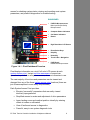
1
Pixel Control System
Installation & Adjustment
For Traction Elevator Applications
Utilizing AC Vector or DC Drive Motor Control
Product Documentation that’s Simple to NavigateTM
This is the Installation and Adjustment Manual that is the guide for
installation, startup and final adjustment of all Pixel Traction Series
elevator controllers. Other resources include:
• Motor Drive Specific Manuals
• Maintenance & Troubleshooting Training Manual provided in
conjunction with Factory and Customer Site technical training classes
• Telephone Technical Support available for Customers at no charge
•
call: 916/428-1708
•
e-mail: [email protected]
•
fax: 916/428-1728
• Onsite Product & Engineering Support available worldwide by prior
arrangement.
All information contained herein is confidential and proprietary to
Elevator Controls Corporation. This document shall not be used or
reproduced,
in whole or part, without the prior written consent of Elevator Controls.
Pub ID: Pixel-V900-T-Man- rev 07-22-13
© 2013 Elevator Controls Corporation
Table of Contents
Introduction
Section 1
1.1
1.2
1.2.1
1.2.2
1.3
1.3.1
1.3.2
1.4
1.4.1
1.4.2
1.4.3
1.4.4
1.4.4.1
1.4.4.2
1.4.4.3
1.4.4.4
1.4.4.5
1.4.4.6
1.4.4.7
1.5
1.5.1
1.5.2
1.5.3
1.5.4
1.5.5
1.5.6
1.5.7
1.6
1.6.1
1.6.2
1.6.3
1.6.4
CONVENTIONS IN THIS MANUAL
Warning, Caution, and Note Icons
System Menu Navigation
viii
x
PIXEL OVERVIEW
System Description, Capabilities and Advantages
System Components
Typical System Components
Pixel Traction Series Capabilities
About Pixel
Typical Pixel Controller Layout
Typical Pixel TOC Top of Car Interface
New Technology, New Terms
Pixel Dashboard – Overview
Pixel Dashboard – Screen and Navigation
Pixel Screen – Home/Startup Display
Quick Reference to Home/Startup Screen Display
Visual Door Status
Modes of Operation
Intended Direction
Current and Destination Floors
Speed
Control System Configuration
Active Fault
Pixel New Features Quick Overview
Landa Dual Positioning System
Virtual Safety Limits
CAN-bus Network
Parallel Independent Safety Processors
Integrated I/O Testing and Remapping
Consolidated Field Wiring
Remote Assist
Pixel Menu System Overview
Home/Startup Menu – Top Tier
Install Menu – Second Tier
Adjust Menu – Second Tier
Troubleshoot Menu – Second Tier
1
2
3
5
6
6
7
7
7
9
10
11
11
12
12
13
13
13
13
13
13
14
14
14
14
15
15
15
15
16
16
17
EC Pixel Traction Controller Installation & Adjustment Manual
ii
Section 2
2.1
2.2
2.3
2.4
2.5
YOUR INSTALLATION PLAN
General Information
Installation Considerations
Environmental Considerations
Recommended Tools, Test Equipment & Manuals
Controller Wiring Guidelines
18
18
19
19
21
Section 3
3.1
3.2
3.3
3.3.1
3.3.2
3.3.3
3.3.4
3.3.5
3.3.6
3.3.7
3.3.8
3.3.9
3.3.10
3.3.11
3.3.12
3.3.13
3.4
3.4.1
3.4.2
3.4.3
3.4.4
3.4.5
3.5
3.5.1
3.5.2
3.5.3
3.5.4
3.5.4.1
3.5.4.2
3.5.4.3
3.5.5
3.5.5.1
INSTALL THE CONTROL SYSTEM
Pixel Traction Control System Steps to Startup
Install the Controller Cabinet
Wire the Control System
Test Ground Continuity
Remove Primary Controller Fuses
Place Disconnect Switch in Off Position
Wire Main Line to Controller
Verify Supply Voltages at Equipment
Pixel Dashboard Interface – Indicators
Verify Motor, Encoder, and Brake Data Tag Information
Identify the Correct Appendix for Your Drive
Verify Drive Parameters
Auto Tune Drive
Enable Construction Mode of Operation
Wire Circuits Required for Construction Mode
Verify Speed Parameters
Run the Car on Construction Mode
Attempt to Move Car
Brake Adjustment
Brake Mechanical Operation
Verify Car Speed
System Startup Complete
System Components Installation and Wiring
TOC Box Installation
COP Installation Wiring
Traveler Cable Installation and Wiring
Landa Positioning System Installation
Encoded Tape
Landa Dual Sensor Head Installation and Wiring
Landa Positioning System Verification
Cab and Hoistway Wiring
Mechanical Switches and Peripherals Wiring
23
23
23
23
24
24
24
25
25
27
27
28
28
29
29
31
33
33
34
34
34
34
35
35
35
35
36
36
36
36
37
37
EC Pixel Traction Controller Installation & Adjustment Manual
iii
3.5.5.2
3.5.6
3.6
3.7
3.8
3.9
3.9.1
3.9.2
3.9.3
Section 4
4.1
4.2
4.3
4.4
4.5
4.6
4.6.1
4.6.2
4.6.3
4.6.4
4.6.5
4.6.6
4.6.7
4.6.8
4.6.9
4.6.10
4.6.11
4.6.12
4.6.13
4.6.14
4.6.15
4.6.16
4.6.17
4.6.18
4.6.19
4.6.20
4.6.21
4.6.22
4.7
Hall Network
Verify Network Communication
Disable Construction Mode of Operation
Verify Hoistway Clearance
Verify Connectors Properly Seated
Hoistway Position Learn
Mechanical Limit Switches
Virtual Limits
Floor Setup
37
38
30
39
39
40
40
41
43
FINAL ADJUSTMENT
Door Adjustment
Check Hoistway Clearances
Use of Test Switch
Intentionally Left Blank
Intentionally Left Blank
Speed Profile Parameters
Position & Velocity Feedback System (PVF)
Parameters for Position & Velocity Feedback
Contract Speed
Inspection Speed
Leveling Speed
Re-leveling Speed
Initial Jerk
Rollover Jerk
Deceleration Jerk
Acceleration
Deceleration
Leveling Decel Time
Leveling Distance
Pattern Delay
Pre-Torque Option
Highspeed Trip Speed
Inspection Trip Speed
Leveling Trip Speed
Earthquake Trip Speed
Terminals % Trip Speed
Level Zone
Door Zone Center
Speed Profile Adjustment
46
46
46
47
47
47
48
49
49
50
50
51
51
52
53
54
54
55
55
56
56
57
57
58
59
59
60
60
60
EC Pixel Traction Controller Installation & Adjustment Manual
iv
4.7.1
4.7.2
4.7.3
4.7.4
4.7.5
4.7.6
4.7.6.1
4.7.6.2
4.7.6.3
4.7.7
4.8
4.9
Get Car Ready to Run in Test Mode
Reset Non-TEST Modes
Entering Calls to Run in Test Mode
Run Car to Every Landing
Adjust Floor Levels
Final Ride Adjustment
Speed Pattern Adjustment
Decreasing Brake-to-Brake Time
Improving Passenger Comfort
ETS Learn
Verify Overall Car Performance
Transfer Safety Configuration File to Microprocessors
61
62
62
63
63
64
64
64
65
66
67
67
Section 5
5.1
5.1.1
5.1.2
5.1.3
SPEED MONITORING ADJUSTMENT
Car Speed Monitoring System
Defining Overspeed
Monitoring Overspeed
Speed Monitoring Adjustment
69
69
70
70
Section 6
6.1
6.2
6.3
6.4
6.4.1
6.4.2
6.4.3
6.4.4
6.5
6.5.1
6.5.2
6.5.3
6.5.4
6.6
6.7
6.7.1
6.7.2
6.8
6.9
6.9.1
CODE COMPLIANCE VERIFICATION
Performing Elevator Safety Tests & Inspections
Intentionally Left Blank
Intentionally Left Blank
Safety Speed Tests
Car Buffer Test – Fully Loaded Car
Counterweight Buffer Test – Empty Car
Safety Overspeed – Fully Loaded Car
Emergency Terminal Stop
Overspeed Tests
Inspection Overspeed
Leveling Overspeed
Earthquake Overspeed
Contract Overspeed
Governor Test
Terminal Stopping Devices
Terminal Stopping Devices
Final Terminal Stopping Devices
Landa Redundant Position System Verification
Monitoring Compliance Verification
EB1-EBS and EBX1-EBX2 Relays Contacts
73
73
73
73
73
75
76
77
79
79
80
81
83
84
85
85
86
88
91
91
EC Pixel Traction Controller Installation & Adjustment Manual
v
6.9.2
6.9.3
6.9.4
6.9.5
6.9.6
6.9.7
6.9.8
6.9.9
6.9.10
AA Motor Contactor Force Guided Relay
P Potential Force Guided Relay
BK Brake Relay
Hoistway & Car Door Bypass Switches
Detection of Jumpers on Door Safety String
Door Open and Close Simultaneously
Unintended Movement
Single Ground
Permit Car Speeds Over 150 fpm
92
92
92
93
95
96
97
99
100
Section 7
7.1
7.2
7.3
7.3.1
TROUBLESHOOTING
General Troubleshooting Tips
General Checklist
Fault Help Menu Navigation Example
Troubleshooting Example
101
101
102
102
Section 8
Section intentionally left blank
104
Section 9
9.1
9.2
9.2.1
9.2.2
9.2.3
9.2.4
9.2.5
MAINTENANCE
Maintenance
Replacement Parts List
Elevator Controls PC Boards
Relays
Fuses
Modules
Semiconductors
105
105
105
105
105
106
106
Appendix A1
A1
A1.1
A1.2
A1.3
A1.3.1
A1.3.2
A1.3.3
A1.4
A1.5
A1.6
A1.7
A1.8
L1000A Vector Drive for Induction Motors
L1000 Elevator Drive Overview
Drive Interface Overview
Job Parameters Verification
Autotuning
Preset Pxiel Interface for Autotuning
Motor Autotuning
Reset Pixel Interface following Autotuning
Motor Rotation Verification
Commanded vs Measured Speed Calibration
Motor Control
Overspeed Using the Drive to Drive the Hoist Motor
Program Run Output to Drive Ready
107
107
107
108
108
109
109
110
110
111
112
113
Appendix A2
A2
L1000A Vector Drive for PM Motors
L1000 Elevator Drive Overview
114
EC Pixel Traction Controller Installation & Adjustment Manual
vi
A2.1
A2.2
A2.3
A2.3.1
A2.3.2
A2.3.3
A2.4
A2.5
A2.6
A2.7
A2.8
Drive Interface Overview
Job Parameters Verification
Autotuning
Preset Pxiel Interface for Autotuning
Motor Autotuning
Reset Pixel Interface following Autotuning
Motor Rotation Verification
Commanded vs Measured Speed Calibration
Motor Control
Overspeed Using the Drive to Drive the Hoist Motor
Brake Control Output to Drive Ready
114
115
115
115
116
119
119
119
120
122
122
Appendix A3
HPV-900 Drive for Induction Motors
Appendix A4
HPV-900 Drive for PM Motors
Appendix A5
Conbivert F5 Drive for Induction Motors
Appendix A6
Combivert F5 Drive for PM Motors
Appendix A7
Quattro AC Drive for Induction Motors
Appendix A8
Quattro AC Drive for PM Motors
Appendix B1
B1
B1.1
B1.2
B1.3
B1.4
B1.5
B1.6
B1.7
B1.8
DSD-412 DC Drive
DSD-412 Elevator Drive Overview
Drive Interface Overview
Job Parameters Verification
Autotuning
Motor Rotation Verification
Commanded vs Measured Speed Calibration
Motor Control
Overspeed Using the Drive to Drive the Hoist Motor
Brake Control Output to Drive Ready
123
123
123
126
128
129
130
132
133
Appendix B2
B2
B2.1
B2.2
B2.3
B2.4
B2.5
B2.6
B2.7
B2.8
Quattro DC Drive
Quattro Elevator Drive Overview
Drive Interface Overview
Job Parameters Verification
Autotuning
Motor Rotation Verification
Commanded vs Measured Speed Calibration
Motor Control
Overspeed Using the Drive to Drive the Hoist Motor
Brake Control Output to Drive Ready
134
134
135
136
137
138
139
141
142
Appendix XX
Index
Pixel Complete Menu System Map
EC Pixel Traction Controller Installation & Adjustment Manual
vii
Introduction
Conventions in this Manual
Warning, Caution, and Note Icons
Throughout this manual, icons call attention to text that issues
safety warnings, cautions, and/or notes to which particular
attention should be paid.
WARNING: Operating procedures or practices that may
result in personal injury and/or equipment damage if not
followed correctly.
CAUTION: Operating procedures and practices that may
result in equipment damage if not correctly followed.
NOTE: Useful information or procedures.
All instructions in this manual assume that work will be done by
qualified field personnel, trained and experienced in the installation
of elevator equipment. No attempt has been made to define terms
or procedures that should be familiar to qualified elevator
personnel.
CAUTION: Equipment installation must comply with all
Local and other applicable Elevator and Electrical Codes
and regulations.
NOTE: It is assumed that all switches serving as stop
and overtravel limits – at both terminal landings – have
been verified to be of the proper type, correctly placed
and operating as intended.
This manual is intended only to acquaint elevator personnel
with the information required to successfully install the Pixel
elevator control system. Installation personnel must be familiar
EC Pixel Traction Controller Installation & Adjustment Manual
viii
with all codes and regulations pertaining to safe installation and
operation of the elevator systems.
WARNING: THE AC POWER SUPPLIED to this
equipment must be provided through a PROPERLY
FUSED DISCONNECT OR CIRCUIT BREAKER.
Improper circuit protection may create a
HAZARDOUS CONDITION.
CAUTION: Restrict access to elevator control equipment
and apparatus to qualified personnel only.
NOTE: Installation and wiring must be in accordance
with the National Electrical Code and consistent with all
local codes, as well as National elevator codes and
regulations.
NOTE: Connection of field wiring to controller terminals
must be accomplished in a neat and careful manner.
Stranded wire conductors must be twisted together to
avoid any strands that, if left out of terminals, would
create potential shorts. All controller connections, field
terminals, and cable connectors must be checked to be
sure they are tight and properly seated. When
connecting flat cable connectors, take care to match pin
#1 marks (arrow symbol on connector, red stripe on
cable) to prevent damage.
EC Pixel Traction Controller Installation & Adjustment Manual
ix
Conventions in this Manual
System Menu Navigation
The Pixel system has a very powerful and flexible set of menus.
To view and access selections, a high resolution color LCD
screen has been paired with an intuitive Touch & GoTM
selection knob. Simply rotate to scroll up and down any
selection list. Then press to select the desired function (or
setting) and keep right on working.
DASHBOARD
•
High Resolution LCD Screen
•
•
Direct-Select Keys
Help Key
•
Home Key
•
Touch & GoTM Navigation
Figure i1 – System Access Point
Above the silver Touch & Go knob – within easy reach – are six
key. The GREEN key is Home, the YELLOW key is Help, and
the four GREY keys between have menu-specific functions.
GREY keys are Direct-Select keys, for which function labels
appear just above the keys at the bottom of the LED screen,
based on the specific menu being viewed.
EC Pixel Traction Controller Installation & Adjustment Manual
x
Throughout this manual, visual shorthand is used to describe
how to quickly locate and interact with various menus and
options.
Pixel Navigation Icons
Knob Rotate/Push
Key Press
Rotate to locate
Home
Push to select
Direct-Select
Help
Figure i2 – Pixel Visual Shorthand Navigation Icons
Narrative Navigation Instructions too Complicated
This manual might instruct you to press the Green HOME key,
then use the Touch & Go knob to navigate to INSTALL. Once
this selection is highlighted, select it by pressing the Touch &
Go knob. Then use the knob again, to navigate to ABOUT.
Press to select.
Visual Shorthand: Simplified version of the instructions above.
Home
Install About Another Example: Modify Fire Return Floor
Home
Adjust Select Car Performance Fire Return Floor Select New Value Save or Cancel
EC Pixel Traction Controller Installation & Adjustment Manual
xi
Section 1 – Pixel Overview
1.1
System Description, Capabilities & Advantages
The Pixel Traction Control System uses advanced technology to
enable more routine tasks to be accomplished faster.
Everything about Pixel has been designed to save field labor time.
This digital elevator control system provides three points of system
access – Machine Room, Cartop, and Inside the Cab – so the most
convenient location can be used to complete tasks quickly and easily.
Each of the three system access points includes a vivid color LCD
display, unique Touch & GoTM interface, one-button access to contextresponsive help, and intuitive direct-select keys. Instant real-time
awareness of current car operation is provided on all displays when not
otherwise in use.
The LandaTM car positioning system provides absolute cab position
information with high tech accuracy – using dual sensor heads to track
cab position to 0.8 millimeter. Landa components are mounted quickly
– all limits, slowdowns and landings are defined virtually, stored
digitally, and easily readjusted. No need to install or wire vanes or
switches in the hoistway (except top and bottom physical limit switches
as required by elevator safety code).
Powerful yet simplified diagnostics are built into each system
access point, including the ability to intuitively view and easily
reprogram elevator “personality” parameters onsite. Review and adjust
drive parameters, access fault diagnostics and playback the operating
sequence leading to a fault notification.
The integrated Pixel control system package typically includes the
car controller, cartop box with access point, COP access point, Landa
positioning system, and hall nodes that communicate using EC’s
enhanced c-LINKTM CAN-bus serial communication system. c-LINK
reduces wire count for hall, car and cartop signals without
compromising EC’s Safe & SensibleTM standards.
Dual CAN-bus controller area networks provide high speed internal
system communication. Use of this industrial standard communication
protocol opens the door to interoperability with a variety of current and
future products and peripherals – including the latest door operators.
EC Pixel Traction Controller Installation & Adjustment Manual
1
Overall reliability is enhanced by surface-mount electronic
components, large scale integrated circuits, and state-of-the-art PC
boards.
When the power of technology is used to simplify essential tasks –
including installation, adjustment, maintenance and troubleshooting –
everybody wins.
1.2
System Components
The Pixel system design is based on a dual high speed CAN-bus
controller area network communications architecture, which supports
group operation for up to twelve cars. The most basic component – a
car control system – is made up of the following:
a Pixel Car controller
b P-TOC Pixel top of the car interface controller
c
P-COP Pixel car operation panel interface controller (one per
COP; up to four per car supported)
d P-HALL Pixel hall nodes (as required for hall calls, fire recall,
gongs, etc)
e Landa™ dual sensor car positioning system
EC Pixel Traction Controller Installation & Adjustment Manual
2
1.2.1
Typical System Components
The Pixel control system – depending on the
specific application – typically includes:
a Pixel Car Controller
The Pixel car controller is usually
located in a machine room or – in
machine-room-less applications, in an
equipment closet. Various enclosures
are available to fit your
specific application… and meet your
NEMA rating requirements.
b P-TOC Pixel Cartop Interface
The cartop system access point
provides access to configuration
information, parameters and
diagnostics. The cartop interface box
provides a convenient wiring termination
for Landa, door operator, load weigher,
safety edge, cab light and fan, traveler
cable and the provided TOC-to-COP
wire harness. Optional (similar to
photo) cartop inspection station with
light and service outlet is available.
c
P-COP Pixel Car Operating
Panel Interface
A system access point is located at
each COP. EC-Ready COP Fixtures
fully interconnect to the TOC box using
the provided TOC-to-COP harness.
One wiring harness is provided for each
of up to four COP’s per cab.
EC Pixel Traction Controller Installation & Adjustment Manual
3
d P-HALL Pixel Hall Nodes
Universal hall nodes can provide
connections for hall calls, fire recall,
access, hall gongs, code blue calls and
more.
Each CAN-driven node supports two I/O
easily configurable using onboard
switchgear.
e Landa™ Dual Positioning System
Landa is a dual positioning system that
provides absolute cab location
information without the need for vanes
or switches in the hoistway.*
Dual communication channels, one for
each positioning system, provide truly
independent redundancy for failsafe
operation.
Landa provides precision accuracy –
tracking cab location to within 0.8
millimeter.
* Top and bottom physical limit switches
must be provided as required by elevator safety code.
EC Pixel Traction Controller Installation & Adjustment Manual
4
1.2.2
Pixel Traction Series Capabilities
Speed
1400 fpm | 7 mps
Stops
128 Stops maximum with selective door operation
Group Size
12 cars maximum
Environment
32 to 104 degrees Fahrenheit | 0C to 40C degrees
Altitude to 12,000 feet | 3,658 meters
95% relative humidity (non-condensing)
Motor
Control
AC induction or permanent magnet hoist motor
Variable voltage variable frequency VVVF elevator
drive with encoder feedback
DC hoist motor
SCR elevator drive with encoder feedback
Positioning
Landa™ absolute car positioning system using dual
sensor heads and coated tape to track position
accuracy to 0.032” (0.8mm)
EC Pixel Traction Controller Installation & Adjustment Manual
5
1.3
About Pixel
1.3.1
Typical Pixel Controller Layout
PC BOARDS & COMPONENTS
•
P-MP-IO Microprocessor
Main Input/Output Safety
Microprocessor
•
P-PDB Power Distribution
Board
•
P-MP Pixel Microprocessor
Board with onboard diagnostics
•
Power Transformer
•
24 VDC Power Supply
•
Motor Control Drive
•
Brake and Potential Contactors
•
Field Wiring Terminals
•
Motor Isolation Contactor
Figure 1.3.1 – Typical Pixel Car Controller
EC Pixel Traction Controller Installation & Adjustment Manual
6
1.3.2
Typical Pixel TOC Top of Car Interface
The Pixel TOC Top of Car Interface is provided with all mounting
hardware required to fasten it to the crosshead rail on the cartop.
COMPONENTS & SWITCHGEAR
•
Traveler termination, COP
interconnection, Cab Lights and
Fans Terminals
•
P-Aux System Access Point
Screen and Dashboard
•
Optional Cartop Inspection
Switchgear and Light
•
24 VDC Power Supply
•
P-TOC Cartop Microprocessor
Board
Figure 1.3.2 – Typical Pixel Cartop Interface
1.4
NOTE: The P-TOC Top-of-Car Interface can optionally
include a cartop inspection station, with light and service
outlet, as an option (similar to picture).
New Technology, New Terms
Our goal was to design the Pixel system using advanced
technology to simplify routine tasks – so you can accomplish
more, faster.
Lots of traditional tasks are done with Pixel using a new, time saving
approach. Here’s a quick tour of key system components. We’ve
developed some new terms to make your transition to Pixel easy.
1.4.1
Pixel Dashboard – Overview
Complete tasks more easily and quickly by working from the
most convenient location.
Pixel concentrates switchgear, indicators, readouts and a vivid color
LCD display into an intuitive dashboard. The primary system access
point is the controller in the machine room.
Two convenient additional system access point locations are provided
– on the cartop, and inside the car operating panel. These provide
EC Pixel Traction Controller Installation & Adjustment Manual
7
access for checking system status, viewing and resetting most system
parameters, and powerful diagnostics for troubleshooting.
DASHBOARD
•
P-MP-IO Microprocessor
Main Input/Output Safety
Microprocessor
•
Computer Status Indicators
•
Car Status Indicators
•
Resets
•
High Resolution LCD Screen
•
•
Direct-Select Keys
Help Key
•
Home Key
•
Touch & GoTM Navigation
•
P-MP Board
Dashboard Microprocessor
Figure 1.4.1 - Pixel Dashboard Overview
Pixel displays information on a vivid, full color LCD screen at each
system access point. Instant real-time awareness of current car
operation is provided on all system screens, when not otherwise in use.
The vast majority of functions and parameters can be viewed and
changed from any of the three system access point locations (there are
just a few exceptions to meet safety requirements).
Each System Access Point provides:
•
Elevator “personality” parameters that are easily viewed
intuitively reprogrammed
•
Simplified access to review and adjustment of drive parameters
•
Learn landing zones and readjust position virtually by entering
offsets in inches or millimeters
•
View of faults and access to diagnostics
•
Powerful, easy to use system diagnostic tools
EC Pixel Traction Controller Installation & Adjustment Manual
8
1.4.2
Pixel Dashboard – Screen and Navigation
Pixel uses a simple knob for navigation and selection – called
‘Touch and GoTM’ – everything you need is at your fingertips.
Pixel’s high resolution color LCD screen is paired with a simple,
intuitive selection knob called the Touch & GoTM interface. Rotate to
scroll up and down any selection list. Then – press this same knob – to
select the desired function (or setting) and keep right on working.
SCREEN & NAVIGATION
•
High Resolution LCD Screen
•
•
Direct-Select Keys
Help Key
•
Home Key
•
Touch & Go
TM
Navigation
Figure 1.4.2 – Pixel Screen & Navigation
The dashboard provides a dedicated YELLOW button for immediate
access to context-responsive help if needed.
Depending on the menu or parameter display being viewed, flexible
GREY direct-select keys are assigned helpful functions.
Return to the main menu at any time by pressing the GREEN home
key.
EC Pixel Traction Controller Installation & Adjustment Manual
9
1.4.3
Pixel Screen – Home/Startup Display
Pixel’s screens continuously display information –
understood ‘at a glance’ – from multiple system access
points.
The top third of the
home screen displays
useful system
information – whether
seen in the machine
room, on the cartop, or
in the cab.
This view appears on
system startup Figure
1.4.3a. The icons and
text information are
each identified below
for reference Figure
1.4.3b and described in
detail on the following
pages.
EC Pixel Traction Controller Installation & Adjustment Manual
10
1.4.4
Quick Reference to Home/Startup Screen Display
1.4.4.1 Visual Door Status
Available door openings are displayed as active (in green) or inactive
(in grey) using center parting door icons. Visual door status is
indicated as follows:
•
Opened
Small portion of door on each side of opening
•
Closed
Solid green door panels indicated
•
Opening
Animation: doors moving partly to fully open
•
Closing
Animation: doors moving partly to fully closed
•
Faulted
Solid red door panels indicated
EC Pixel Traction Controller Installation & Adjustment Manual
11
1.4.4.2 Modes of Operation
Construction mode, when enabled, restricts operation to
inspection mode with limited speed and no positioning.
Pixel supports multiple modes of operation including:
Automatic
Inspection
Construction
•
Main Fire Recall
•
Cartop Inspection
•
Alternate Fire Recall
•
In Car Inspection
•
•
•
Fire Phase 2
•
Hoistway Access
•
Emergency Power Phase 1
•
Controller Inspection
•
Emergency Power Phase 2
•
Emergency Power Pre-transfer
•
Battery Rescue Operation (traction)
•
Battery Lowering Operation (hydraulic)
•
Fire Service
•
EMT Phase 1
•
EMT Phase 2
•
Hospital Service
•
Earthquake Normal Mode
•
Earthquake Abnormal Mode
•
Test
•
Capture
•
Independent
•
Wild / Sabbath
•
Security
•
Out of Service Recall
•
Car to Lobby
•
Flooded Pit Recall
•
Piston Synchronization (hydraulic)
•
Viscosity Operation (hydraulic)
•
Car Overloaded
•
Attendant Service
Cartop Inspection
In Car Inspection
1.4.4.3 Intended Direction
When car direction is determined, the Pixel screen will display a solid
up Green or down Red directional arrow. If direction has not been
assigned, both arrows appear in outline.
EC Pixel Traction Controller Installation & Adjustment Manual
12
1.4.4.4 Current and Destination Floors
The Pixel screen displays the current floor at all times, found
between the up and down directional arrows, indicated in three
digits.
If a destination floor has been assigned, it will be displayed just
below the current floor, labeled Target, indicated in three digits. The
Target is dynamic, and may change during a run.
1.4.4.5 Speed
The Pixel screen displays cab speed, just to the right of the Front
door icon. Scale can be toggled between fpm (feet per minute) and
mps (meters per second).
1.4.4.6 Control System Configuration
The Pixel screen displays system configuration, just to the left of the
Rear Door icon. Car configuration can be Simplex or Group. In
group configuration, the current priority to assume dispatching
functions for the group is indicated, under the word ‘Group’.
1.4.4.7 Active Fault
The Pixel screen displays the active fault with the highest priority or
No Faults if none present.
NOTE: Faults are classified as either latching or nonlatching. While non-latching faults self reset, all faults are recorded
in fault counters and logs.
1.5
Pixel New Features Quick Overview
1.5.1
LandaTM Dual Positioning System
No more time consuming and costly hoistway work
mounting vanes, wiring and readjusting switches.
Landa is a dual positioning system that provides absolute cab
location information. Dual communication channels, one for each
positioning system, provide truly independent redundancy for failsafe
operation.
Landa provides precision accuracy – tracking cab location to within
0.8 millimeter. All limits, slowdowns and landings are defined
virtually, stored digitally, and easily readjusted. No wiring, vanes or
EC Pixel Traction Controller Installation & Adjustment Manual
13
switches are required in the hoistway (*except top and bottom
physical limit switches as required by elevator safety code).
1.5.2
Virtual Safety Limits
Pixel remembers where the car is at all times.
The Landa car positioning system captures high resolution position
data that is maintained through power cycling. During the hoistway
‘learn’ procedure, the control system generates and records the
location and associated position for all required virtual safety limits.
Once learned, virtual safety limits function in the same way that vane
and switch systems worked in the past. Safety code requires
placement of top and bottom physical limit switches, for which Pixel
provides inputs (described in the wiring Section).
1.5.3
CAN-bus Network
Proven industrial standard communication protocol
provides simplified interoperability using high speed dual
CAN-bus networks.
The Pixel controller uses dual CAN-bus controller area networks to
provide high speed internal system communication, including group
to and between individual car controllers. Use of this industrial
standard protocol opens the door to interoperability with a variety of
current and future products and peripherals – including the latest
door operators.
1.5.4
Parallel Independent Safety Processors
If at any time, Pixel’s two independent safety systems do
not agree, an automatic system shutdown is executed to
keep passengers safe.
In compliance with current elevator safety code, Pixel’s design
incorporates parallel independent safety processors. Two
independent, redundant means are used to monitor safe operation.
The logic output from both safety systems is continually compared.
EC design engineers devised SP1, a powerful software-based safety
processor, which is continually crosschecked by SP2, a hardwarebased FPGA (floating point gate array) safety processor.
EC Pixel Traction Controller Installation & Adjustment Manual
14
1.5.5
Integrated I/O Testing and Remapping
Local diagnostics function whether or not the access point
has an active connection to the system network.
Pixel has designed-in reliability and flexibility. Simple onboard I/O
testing is supported at each system access point. Every I/O is
provided with an associated LED indicator.
If an I/O is found to have failed, remap I/O can be used to reassign
this I/O to another location on the same PC board, or to another IO
board, using an intuitive, visually-based process.
1.5.6
Consolidated Field Wiring
Consolidated field wiring saves time while separating low
and high voltage signals to help prevent component
damaging wiring errors.
The Pixel controller cabinet has been designed so you can bring
field wiring into a functional assigned color coded terminal strips – a
convenience we call consolidated field wiring.
1.5.7
Remote AssistTM
Virtual tech support is delivered to your machine room on
demand – with system access you always approve and
control.
Elevator mechanics have long wished that support technicians could
join them in the machine room with a simple call for help. Remote
Assist enables the Pixel technical support team to virtually view the
system you are working on, in real time, and provide guidance and
recommendations.
1.6
Pixel Menu System Overview
Menu content is strategically organized, and logically
sequenced, with related tasks grouped together.
The broad range of selections within the Pixel system are presented
in menus, each containing a reasonable number of selections within
each tier. The number of tiers has also been minimized to simplify
navigation and selection.
The breadth and depth of the Pixel menu system provides access to
the extensive parameters demanded by the most experienced
adjuster. But many installers will find that the top two or three menu
tiers will satisfy the majority of their needs.
EC Pixel Traction Controller Installation & Adjustment Manual
15
1.6.1
Home/Startup Menu – Top Tier
The Pixel home menu displays on startup – or whenever the green
Home key is pressed.
This screen displays a greeting message, “Hi, I’m Pixel. What would
you like to do?” along with the following Menu options:
•
Install
•
Adjust
•
Troubleshoot
•
Date/Time display/reset
Start by selecting one of three basic tasks – Install, Adjust, or
Troubleshoot – by using the Touch & GoTM knob to scroll through
selection options. When your desired selection is highlighted, press
the knob to select.
Note that system date/time settings and preferences are accessed
from the Home screen as well.
1.6.2
Install Menu – Second Tier
The Install menu presents a range of options which are roughly
organized in the most likely sequence in which tasks will be
completed:
•
About
•
Initial Settings
•
View Selector Data
•
Learn Functions
•
Code Compliance Test
•
Construction Mode
•
File Transfer
•
I/O Mapping
•
Contact
Again, the Touch & GoTM knob is used to scroll through selection
options. When your desired selection is highlighted, press the knob to select.
Each of these options, and their submenus, are presented in detail in
Section 3 – Install the Control System.
EC Pixel Traction Controller Installation & Adjustment Manual
16
1.6.3
Adjust Menu – Second Tier
The Adjust menu presents a range of options for optimizing ride, car
and group dispatching performance:
•
About
•
Car Performance
•
Ride Performance
•
Group Performance
•
Contact
The Touch & GoTM knob is used to scroll through selection
options. When your desired selection is highlighted, press the knob to select.
Each of these options, and their submenus, are presented in detail in
Section 4 – Final Adjustment.
1.6.4
Troubleshoot Menu – Second Tier
The Troubleshoot menu presents a range of tools designed to
simplify and expedite system troubleshooting if required:
•
About
•
Single Call Enter
•
Auto Car Call Simulation
•
View Selector Data
•
Drive
•
Controller Network
•
Flags
•
Fault Logs
•
Sequence Log
•
Local Diagnostics
•
Contact
The Touch & GoTM knob is used to scroll through selection
options. When your desired selection is highlighted, press the knob to select. Each of these options, and their submenus, are
presented in detail in Section 7 – Troubleshooting.
EC Pixel Traction Controller Installation & Adjustment Manual
17
Section 2 – Your Installation Plan
2.1
General Information
This section contains important instructions and recommendations to
ensure successful Pixel Control System installation.
Successful installation and reliable, trouble free operation of all elevator control
equipment depends on proper assessment of the installation environment and
proper wiring methods. Completing both correctly protects equipment from
disruption by external sources.
2.2
Installation Considerations
When selecting the best physical location for the control equipment consider the
following:
a. Make sure the control system is placed logically, while taking into
consideration all elevator system components and non-elevator equipment
sharing the space.
b. Provide adequate working space for control system installation, wiring, and
maintenance. Elevator Controls standard equipment enclosures require
front access only. This eliminates many constraints that would otherwise
limit how equipment can be located.
c. Do not install equipment where it may create a hazard.
WARNING: Install Pixel Control equipment according to all
applicable electrical, fire, and building codes. Improper
installation and/or equipment location may create a
HAZARDOUS CONDITION.
d. Do not install control system components in areas or on surfaces where
there is exposure to vibration that may be produced by other equipment.
Modern control systems contain socket-mounted parts whose function may
be compromised by vibration.
e. Provide adequate lighting for safety and efficiency.
f. An internet connection, with fixed IP address, is desirable for access to
Remote AssistTM from the EC factory technical support team.
g. If wireless service at the installation location is poor or intermittent, have a
wired phone installed in the machine room.
EC Pixel Traction Controller Installation & Adjustment Manual
18
2.3
Environmental Considerations
The elevator control system should be installed according to the following
requirements to ensure proper operation and longevity:
a. Temperature inside the control system enclosure should be maintained
between 32 and 104 degrees Fahrenheit (0 to 40 degrees Celsius).
Temperatures outside this range may effect normal operation and/or
reduce system life. If required, make provisions for machine room air
conditioning. EC can quote and provide an enclosure-mounted air
conditioning unit.
b. Air in the machine room should be free of corrosive gases and sufficiently
dry to prevent condensation from moisture. NEMA 4 or NEMA 12
enclosures, with integral air conditioning units, are recommended for
applications that do not meet these requirements. EC can quote and
provide the full range of specialized NEMA rated enclosures for proper and
safe operation in non-standard environments.
c. Locate control system enclosures and components away from any window
or opening to minimize the risk of equipment damage due to severe
weather conditions.
d. Protect control system equipment from exposure to extreme levels of
electromagnetic (EM) and radio frequency (RF) radiation. EC control
systems are certified to current EMI/RFI standards though independent
testing by CKC Laboratories, Inc. However, note that EMI and RFI have
the potential to interfere with normal operation of any electronic system.
2.4
NOTE: Hand-held communications devices used close to the system
microprocessors have been known to generate disruptive RF interference.
Recommended Tools, Test Equipment & Manuals
The following tools are recommended for installation:
a. Digital multi-meter
b. Assorted tools used for electronics work such as pliers, cutters, flash light,
EC small straight blade screwdriver (supplied with each controller), etc
c. Amprobe or similar probe equipped ammeter
d. Telephone
e. Test weights
f. Control system “as built” job wiring prints
g. This installation and adjustment manual
h. Motor Drive Control Manual (AC-Vector or DC-SCR as required)
EC Pixel Traction Controller Installation & Adjustment Manual
19
i. Oscilloscope and meter that measures megohms may be desirable for
advanced troubleshooting (rarely required)
j.
2.5
Tachometer to determine actual elevator car speed
Controller Wiring Guidelines
CAUTION: Restrict access to elevator control equipment and apparatus to
qualified personnel only.
NOTE: It is very important to follow control system wiring guidelines to
prevent problems with EMI/RFI interference and feeder line pollution.
NOTE: Wiring to controller terminals must be done neatly and carefully.
Stranded wire conductors must be twisted together, avoiding stray strands
that could create short circuits if not contained in terminals.
NOTE: All terminals and cable connectors should be checked to ensure
that they are properly and solidly seated. When connecting flat cable
connectors, be certain to match pin #1 marks (arrow symbol on
connectors; red stripe on cable) to prevent mechanical damage to
connectors and electrical damage to system components.
There are five wiring entry points provided in order to maintain proper separation
between wiring for various purposes to ensure proper system operation:
a. Power Wiring: The line power feeders and ground coming from the
elevator service disconnect.
b. Motor Wiring: Power wiring to hoist motor, brake and ground.
c. Safety and Logic Wiring: All wiring to fixtures and switches, as well as
signal cross-connect cables from one car to another in a multi-car group
system.
d. Communications Cable: Communication cables run from one controller to
another in a group of two or more cars.
e. Encoder Feedback Cables: Wiring used to provide motor performance
information from the encoder to the drive for speed control.
WARNING: DO NOT CONNECT BUILDING POWER DIRECTLY TO THE
MOTOR CONTACTOR. This will DAMAGE power devices in the drive.
EC Pixel Traction Controller Installation & Adjustment Manual
20
NOTE: The standard EC NEMA 1 enclosure is provided with factory
knockouts for recommended ideal field wiring entry points.
Knockouts and intended use are listed:
a. Top right side
•
Communication cable
b. Middle left side
•
Encoder Feedback cable
c. Middle right side
•
Safety & Logic wiring
d. Lower left and right side
•
Main Line Power wiring
•
Motor and Brake wiring
WARNING: METAL SHAVINGS AND/OR WIRE CLIPPINGS can cause
immediate and delayed DAMAGE to circuits – in any part of the
system – if they bridge or short any circuit or connection. They can
also COMPROMISE SAFE AND PROPER SYSTEM OPERATION if they
become positioned in a way that modifies a circuit or circuits.
CAUTION: Ensure that metallic shavings and/or wire clippings are
minimized and prevented from remaining in any enclosure interior.
Thoroughly check for and remove residue before applying power.
Methods used to capture and remove metal fragments should not be
allowed to create static buildup or discharge.
Good Practice: Soft clean paint brush (gently sweep particles on
enclosure bottom into pile and remove); masking tape (use to remove
particles; create adhesive pocket under intended hole locations with tape
to catch shavings when drilling).
Risky Practice: Use of small vacuum (potential ESD electrostatic
discharge damage); compressed air (may drive particles into inaccessible
or undetectable locations, potential for eye injury).
EC Pixel Traction Controller Installation & Adjustment Manual
21
NOTE: Alternate wiring entry points may be created in the field to
accommodate specific installation conditions.
NOTE: Study your control system layout to develop the best arrangement
for keeping the five entry points separated and laid out logically to suit
your particular application. Following is a proposed ideal Pixel controller
field wiring layout.
EC Pixel Traction Controller Installation & Adjustment Manual
22
Section 3 – Install the Control System
3.1
Pixel Traction Control System Steps to Startup
Protect printed circuit boards from dust and foreign materials.
Remove main fuses. Complete elevator controller mounting,
installation, and wiring.
Observe controller field terminal locations in relation to wiring ducts to determine
optimum locations for wiring to enter the control equipment enclosure.
Complete the steps in Sections 3.2 through 3.4.5 below in order to run the car
on Construction mode.
3.2
CAUTION: Use care to protect circuit boards from metal debris
when cutting.
CAUTION: Do NOT connect the building power supply to the motor
contactor.
CAUTION: Power capacitors in the drive remain charged for some time
after power is removed. Use caution to prevent shock injury.
NOTE: The standard Pixel traction controller enclosure has several ¾”
knockouts marked for wiring ducts which can be used as guides for
location of knockouts required for each particular job.
Install the Controller Cabinet
In Section 2 you reviewed the general considerations for machine room layout
and developed your installation plan. Now, proceed to locate and mount the
controller enclosure.
3.3
Wire the Control System
3.3.1
Test Ground Continuity
Test all terminals for continuity to ground. If continuity is found, resolve the
problem before proceeding.
NOTE: Terminal 3 is connected to ground and used as system common.
EC Pixel Traction Controller Installation & Adjustment Manual
23
3.3.2
Remove Primary Controller Fuses
Remove fuses FL1, FL2, FCT1, FCT2, F4A in order to remove power to controller
logic, brake control circuits, and the door operator. Place Machine Room
Inspection to INSP and the Test switch to TEST. Both switches are located on
the P-MP board.
3.3.3
NOTE: Always review job prints to confirm correct fuse designations and
amperages, as well as to become familiar with job specific circuit
requirements.
Place Disconnect Switch in Off Position
Place the disconnect in the off position, then check voltage on the line side to
verify that all three legs are correct based on job prints page 1.
3.3.4
WARNING: CONFIRM THAT FEEDER LINE VOLTAGE is within 10% of
specified control voltage or PERMANENT DAMAGE could occur to
both the motor drive and elevator control system logic. TURN OFF
THE MAIN DISCONNECT and CORRECT any voltage problem
BEFORE PROCEEDING with installation.
CAUTION: Remove any protective covering that may still be in place on
PC boards and components before applying power.
Wire Main Line to Controller
Wire the main line from the disconnect to the terminal block provided in the
controller enclosure as indicated on job prints page 1.
CAUTION: Do NOT attempt to connect the building power supply to the
drive or motor contactor to prevent damage.
NOTE: Use proper wire size for amperage.
NOTE: Ground wire size must provide equal or greater ampacity than the
incoming feeders.
EC Pixel Traction Controller Installation & Adjustment Manual
24
3.3.5
Verify Supply Voltages at Equipment
Turn on the disconnect switch to verify that voltages at controller terminals are
correct based on job prints page 1. For AC-Vector systems, you may check
voltages on the EMI-RFI or Line Reactor filter input terminals (if the job includes
such filters).
Turn off the disconnect switch then replace the fuses removed previously in
Section 3.3.2 above.
Turn on the disconnect switch and confirm that the motor drive powers up. Verify
that computer power supply input and output voltages are correct based on job
prints page 2. Verify that buss voltages are 24 volts DC for terminals 6, 50, 50F,
and S24V; and 120 VAC for terminal 4A.
Confirm that the P-MP color display is on and the screen shows the Pixel
home/startup display, “Hi, I’m Pixel. What would you like to do?”
3.3.6
NOTE: After verifying input voltages and fuses as required per job prints, if
you are unable to correct conditions to confirm voltages and behaviors
described, call Elevator Controls technical support at 916-428-1708.
Pixel Dashboard Interface – Indicators
You will find multiple LED indicators have been provided on PC boards, and
onboard computer diagnostics are included. Both are very useful tools that will
save installation and troubleshooting time.
NOTE: Review the Pixel system dashboard indicators and
switchgear before continuing to the Section 3.3.7.
EC Pixel Traction Controller Installation & Adjustment Manual
25
SWITCHGEAR
•
•
System Fault Reset
Earthquake Reset
•
Computer Reset
MACHINE ROOM INSPECTION
•
•
•
•
•
Inspection Switch
Up Button
Enable Button
Down Button
Test Switch
DOOR BYPASS PANEL
Figure 3.3.6a - Pixel
Switchgear
•
Hoistway Door Bypass
•
Car Door Bypass
•
Capture Switch
INDICATORS
•
•
Computer Status
Communication Status
•
Car Status Indicators
•
I/O Indicators
•
High Resolution
LCD Display
Figure 3.3.6b - Pixel Dashboard
Indicators
EC Pixel Traction Controller Installation & Adjustment Manual
26
3.3.7
Verify Motor, Encoder, and Brake Data Tag Information
This step confirms that the data provided to manufacture the control system
agrees with actual nameplate data for key components: motor, encoder and
brake.
a. Compare motor nameplate data to that found on the job prints page 1.
b. Compare encoder nameplate data, for type and PPR, to that found on the
job prints page 1.
c. Compare brake nameplate data, for pick voltage, hold voltage, and
resistance, to that found on job prints page 2.
WARNING: DO NOT CONTINUE if any DATA discrepancy is found.
NOTE: If any data does NOT agree with job prints, call Elevator Controls
Technical Support at 916-428-1708. Be prepared with your job number,
nameplate data, and job print data.
3.3.8
Identify the Correct Appendix for Your Drive
A wide variety of drives are available for each unique application in order to
optimize best function for the specific job, budget considerations, and installing
contractor familiarity and preferences. Appendices A (for AC) and B (for DC)
contain drive-specific notes for your unique application, including parameters and
motor auto tuning instructions.
Using the following tables, identify the appendix that corresponds to the drive in
your control system.
Appendix A – AC Vector Motor Control Drives
A1
L1000A drive for Induction Motors
A2
L1000A drive PM Motors
A3
HPV-900 drive for Induction Motors
A4
HPV-900 drive for PM Motors
A5
Combivert F5 drive for Induction Motors
A6
Combivert F5 drive PM Motors
A7
Quattro AC drive for Induction Motors
A8
Quattro AC drive PM Motors
EC Pixel Traction Controller Installation & Adjustment Manual
27
Appendix B – DC Motor Control Drives
B1
DSD-412 DC drive
B2
Quattro DC drive
NOTE: Identify the correct Appendix section for your drive,
then mark the first page for easy reference.
If, for example, you are working with a L1000A drive and THIS manual says,
“Adjust the drive gain, Refer to Appendix Section x1.6, it would refer to Appendix
A1 Section A1.6.
WARNING: DO NOT ATTEMPT TO RUN THE CAR until Sections 3.3.9
to 3.3.13 below are completed.
3.3.9
Verify Drive Parameters
This step confirms that the parameters programmed in the drive agree with the
job prints page DPS. Refer to respective drive Appendix Section x1.2.
WARNING: DO NOT ATTEMPT TO MOVE THE CAR before making
sure ALL PARAMETERS ARE SET in the drive per actual motor
characteristics and MOTOR AUTO TUNING has been successfully
completed.
NOTE: Before attempting to configure drive parameters, study the
manufacturer’s drive manual and the Appendix in THIS manual for your
specific drive.
WARNING: DO NOT CONTINUE if any DATA discrepancy is found.
NOTE: If any drive parameters do NOT agree with job prints, call Elevator
Controls Technical Support at 916-428-1708. Be prepared with your job
number, nameplate data, and job print data.
3.3.10
Auto Tune Drive
This step allows the Drive to calculate the electrical characteristics of the hoist
motor. Refer to Appendix Section x1.3.
EC Pixel Traction Controller Installation & Adjustment Manual
28
WARNING: DO NOT ATTEMPT TO MOVE THE CAR before MOTOR
AUTO TUNING has been successfully completed.
NOTE: If Auto Tune cannot be completed successfully, and you have
exhausted instructions provided in the Drive manual, call Elevator Controls
Technical Support at 916-428-1708 for assistance. Be prepared with your
job number, nameplate data, and job print data.
3.3.11
Enable Construction Mode of Operation
The steps described starting in this section will allow you to operate the car in
Construction mode when you reach the end of Section 3.4.5. Construction Mode
allows the car to be operated on Cartop or In-Car inspection without Landa™
selector feedback – while maintaining elevator safeties consistent with both of
these inspection modes.
Construction mode is enabled or disabled by using the Touch & GoTM knob to
navigate:
Home
Install Construction Mode Pixel Navigation Icons
Knob Rotate/Push
Key Press
Rotate to locate
Home
Push to select
Direct-Select
Enable or Cancel
Help
NOTE: Construction Mode must be set to Disable in order to Enable any
automatic mode of operation.
3.3.12
Wire Circuits Required for Construction Mode
Construction Mode allows the car to be operated on Car Top or In Car inspection
modes. All safety circuits required for these modes of operation must be
operational:
a. Governor switch contact wired between Terminals 4A and GOV.
b. Car Safety String wired between terminals 4A and SAFC.
c. Hoistway Safety String wired between terminals SAFC and SAFH.
d. In Car Emergency Stop Switch between terminals 4A and ESTP.
EC Pixel Traction Controller Installation & Adjustment Manual
29
e. Normal limits wired for UP (terminals 4A and UNL) and DOWN (terminals
4A and DNL).
f. Set HOISTWAY DOOR BYPASS and CAR DOOR BYPASS SWITCHES to
BYPASS position; OR ensure that all car and hoistway gates and locks are
closed.
g. If a Rope Gripper is required, wire monitoring contact between terminals
RG2 and RG3.
h. Wire Motor to Motor Contactor
NOTE: Use proper wire size for amperage.
NOTE: Ground wire size must provide equal or greater ampacity than the
motor power wires.
i. Wire Brake between terminals B1and B2
j.
Wire Emergency brake as required, one of the two following:
1. Rope Gripper between terminals RG1 and RG2
OR
2. Auxiliary (secondary) Brake between terminals B1A and B2A
k. Wire Encoder directly to the drive encoder terminals
NOTE: Encoder must be connected with a single length of properly
shielded cable to work correctly. An encoder cable that is too short must
NOT be spliced but replaced. Contact the supplier that provided the
original encoder cable for a replacement of sufficient length.
NOTE: Refer to job prints page 1 for the encoder wiring diagram.
Particular care must be taken to properly connect shield wiring as shown
on job prints for encoder to work correctly.
l. Wire Inspection Station to controller terminals ICT, ICTE, ICTU, and
ICTD as shown on job prints page 3.
EC Pixel Traction Controller Installation & Adjustment Manual
30
3.3.13
Verify Speed Parameters
NOTE: Even though Pixel’s “This Job” parameters have been factory
preset it is important to verify them, when this manual instructs you to do
so, for optimum system performance.
Pixel’s microprocessor MP calculates and generates the speed pattern that is fed
to the drive to achieve optimum ride and performance. These calculations are
dependent on programmed speed parameters, current car position, and car
speed.
Verify that Pixel speed parameters match job requirement. View parameters,
using the Pixel screen, and compare settings to the speed profile table below.
Home
Pixel Navigation Icons
Install Knob Rotate/Push
Key Press
Rotate to find
Home
Push to select
Direct-Select
Initial Settings Speed Profile EC Pixel Traction Controller Installation & Adjustment Manual
Help
31
Speed Profile Table
SPEED PROFILE
DEFAULT SETTING
Contract Speed
Inspection Speed
Leveling Speed
Re-Leveling speed
Initial Jerk
Roll Over Jerk
Deceleration Jerk
Acceleration
Deceleration
Leveling Decel Time
Leveling Distance
Pattern delay
Pre-Torque
Highspeed trip speed
Inspection Trip Speed
Leveling trip Speed
Earthquake trip Speed
Percentage Overspeed
Level Zone
Door Zone Center
XXX fpm Job Specific
40 fpm
6 fpm
12 fpm
060 fpm
060 fpm
060 fpm
060 fpm
060 fpm
0000 msec
1.0 ft
0000 msec
No
Contract Speed + 10%
100 fpm
100 fpm
132 fpm
10%
0.50 ft
0.2 ft
A general rule of thumb can be useful when setting speed parameters with
preliminary values. During final adjustment these values will be refined, example:
For Contract Speed up to 300 feet per minute
Divide contract speed by three, and use this value to set Jerks,
Acceleration, and Deceleration parameters (marked with in the table).
Example:
Contract speed = 200 feet per minute
Compute 200/3 = 67
Set parameters marked to 67
For Contract Speed above 300 feet per minute
Set all parameters marked to 100
Example:
Contract speed = 400 feet per minute
Set parameters marked to 100
WARNING: CONTRACT SPEED must be entered ACCURATELY to
prevent personal injury and/or equipment damage. A single missing
character (ie: 100 vs 1000) will produce a GREATER THAN INTENDED
EFFECT on speed pattern calculated internally by Pixel.
EC Pixel Traction Controller Installation & Adjustment Manual
32
3.4
Run the Car on Construction Mode
NOTE: Pixel will prevent the car from moving until the required
Construction Mode signal status is achieved.
NOTE: Construction Mode allows the car to run On Car Top or In Car
Inspection to a maximum speed of 50 fpm or the programmed inspection
speed, whichever is less.
Navigate to the home screen, then follow step-by-step instructions.
Home
Confirm that the Pixel screen displays, “No Faults.”
If a fault condition is indicated
Help
Read the fault description and follow instructions for resolving the issue
Once recommended actions are completed press the
System Fault Reset
This will clear a “fault latched” state.
3.4.1
NOTE: The highest priority fault is displayed on the Pixel home screen (No
Faults is the default). Lower priority faults may be revealed once the first
fault is resolved. Repeat instructions above until No Fault are displayed.
NOTE: Faults are classified as either latching or non-latching. While nonlatching faults self reset, all faults are recorded in fault counters and logs.
Attempt to Move Car
Command the car to move on Inspection up or down while observing drive
sheave directional rotation. If directional rotation agrees with commanded
direction skip to section 3.4.2 below.
Refer to Appendix Section x1.4, Motor Rotation verification if necessary to correct
reversed rotation.
WARNING: Motor control, speed, and directional rotation must be
confirmed BEFORE PROCEEDING to section 3.4.2 below.
EC Pixel Traction Controller Installation & Adjustment Manual
33
3.4.2
Brake Adjustment
First, while attempting to run the car, adjust brake pick voltage output by adjusting
RB1 power resistor, and brake holding voltage by adjusting RB2 power resistor to
the desired voltage output, refer to job prints Page 2 for brake power resistors
adjustment instructions.
3.4.3
NOTE: Brake power resistors are located inside the resistor cage on top of
the controller.
Brake Mechanical Operation
Prove that the brake will properly hold at least an empty car. Perform any
necessary mechanical adjustments to obtain proper brake operation. Refer to
brake manufacturer adjustment instructions to perform necessary brake
adjustments.
3.4.4
Verify Car Speed
Command the car to move on Inspection up or down while measuring car speed,
verify commanded vs measured speed agree. If commanded vs measured
speeds agree skip to section 3.4.5 below.
Refer to Appendix Section x1.5, Commanded vs Measured Speed Calibration if
necessary to correc a speed mismatch.
3.4.5
WARNING: Commanded vs Measured speed must agree BEFORE
PROCEEDING to section 3.4.5 below.
System Startup Complete
At this point the system startup is complete: the elevator car should run correctly
on Construction mode in Car Top Inspection or In Car Inspection modes.
If you are unable to run the car, review the steps in Section 3 to section 3.4.5
above, and repeat as required.
Elevator system hardware installation should be completed next, including
installation of the Cartop box, Car Operating Panel, Landa™ dual head
positioning system etc. in order to enable the car to transition from Construction
Mode to Inspection and Automatic modes of operation.
EC Pixel Traction Controller Installation & Adjustment Manual
34
3.5
System Components Installation and Wiring
3.5. 1
TOC Box Installation
The Pixel TOC box is supplied with necessary hardware to permanently attach it
to the crosshead using unistrut and clamps.
Survey the cartop and determine the best quadrant for mounting, setup and ease
of wiring to: door operator(s), load weighing devices, Landa™ positioning
hardware, fans and cab accessories to the TOC box. Refer to job prints page
TOC1 for instructions and details of TOC mechanical installation.
Install the TOC box provided. If your TOC box includes the optional pre-wired Car
Top Inspection Station, install the TOC box the light bulb and light bulb mesh
protection provided. Install the Emergency Stop push button switch.
NOTE: Pixel’s pre-wired Car Top Inspection Station light bulb, light bulb
mesh protection, and the Emergency Stop push button switch are shipped
inside the TOC box.
Once the TOC box has been installed, if you did not order the pre-wired Car Top
Inspection Station, wire the job Inspection Station provided by others to the TOC
Box, referring to page CW of the prints for wiring instructions.
3.5.2
COP Installation Wiring
Refer to your COP panel provider and cab manufacturer for any special
installation instructions for the pre-wired COP panel. Use the harness provided to
connect to the TOC box. Refer to job prints page CW for harness wiring details.
3.5.3
NOTE: A color-coded harness is provided to simplify connection of the
COP(s) to the TOC. One harness is shipped with the TOC box for each
COP.
NOTE: Place the switch for Independent Service to on and leave it on to
make sure car will open doors while transferring from TEST to
Independent service as indicated in Section 4, final adjustment below, to
ensure car will open doors to enable access to cab.
Traveler Cable Installation and Wiring
Install the Traveler Cable and wiring. Refer to your traveler cable provider and
cab manufacturer for any special installation instructions. Refer to page CW of
the prints for traveler wire count as well as for one-to-one terminal wiring
instructions.
EC Pixel Traction Controller Installation & Adjustment Manual
35
3.5.4
NOTE: A separate black terminal strip is provided, in the controller, to wire
one to one the traveler cable conductors to the controller. Another identical
terminal strip is located inside the TOC box. The top portion of the TOC
box terminal strip is intended for termination of traveler cable conductors.
Landa™ Positioning System Installation
3.5.4.1 Encoded Tape
Landa™ Positioning System is supplied with necessary hardware to permanently
attach it to the rails and crosshead using unistrut and clamps. Survey the cartop
and hoistway to determine the quadrant that provides clearance for the Encoded
Tape to run the entire length of the hoistway. Refer to page PS1 of the prints for
installation guidelines.
Start by fastening the top end of the tape to the top-of-hoistway bracket, then
allow the roll to descend down the hoistway.
NOTE: The Encoded Tape is polarized so it must be installed with the start
position at the bottom of the hoistway. To simplify installation, tape has
been coiled with the top end on the outside of the roll.
3.5.4.2 Landa™ Dual Sensor Head Installation and Wiring
The sensor heads can be mounted on any of their three sides to facilitate
encoded tape position and sensor head assemble locations. Refer to page PS1
of the prints for installation guidelines.
Connect the Sensor heads to the TOC box using the color-coded wiring
harnesses provided. Refer to page 6 of the prints for wiring details.
NOTE: The Auxiliary sensor head (selector 2) is the one mounted at the
top of the Landa Dual Sensor Head bracket assembly. It connects to the
TOC JASEL connector on the TOC board. The Main sensor head (selector
1) is the one mounted at the bottom of the bracket, and connects to the
TOC JMSEL connector.
3.5.4.3 Landa™ Positioning System Verification
Using the TOC access point, verify the distance between the two position sensor
heads. Navigating to:
EC Pixel Traction Controller Installation & Adjustment Manual
36
Home
Install Learn Functions Virtual Limits Tape Reader Offset Learn or Back
Verify proper operation of the Landa system. Navigate to:
Home
Install View Selector Data a. Confirm that the position displayed for selector 1 should be smaller than
selector 2. If not, swap the pluggable terminal strips JMSEL and JASEL on
the P-TOC board.
b. Confirm that selector positions increment and decrement together as you
run the car either up or down.
c. Confirm that the RAW delta difference is between 0.7 to1 foot, and roughly
matches the physical distance between the two sensor heads as mounted.
3.5.5
NOTE: If you cannot confirm performance as described above, repeat
steps in Section 3.5.4 until the landing system operates correctly.
Cab and Hoistway Wiring
3.5.5.1 Mechanical Switches and Peripherals Wiring
Refer to page CW of the prints for cab peripherals, such as Door Operator, Photo
Detectors, Fans and Lights, etc. requirements and wiring guidelines. Install and
wire as necessary.
Refer to page HMW of the prints for hoistway switches requirements and wiring
guidelines. Install and wire necessary mechanical switches.
EC Pixel Traction Controller Installation & Adjustment Manual
37
3.5.5.2 Hall Network
Refer to your Fixture manufacturer for any special installation instructions for the
EC-Ready pre-wired Hall Stations. See page HMW of the prints for hall station
node wiring guidelines.
3.5.6
NOTE: CAN-driven hall station nodes require power and data wiring. Care
must be observed not to interchange data wires and power wires so
node(s) will be able to access the network and communicate.
Verify Network Communication
Once wiring has been completed, verify that all network devices are recognized
by the Pixel MP.
Navigate to the home screen, then follow step-by-step instructions to View Car
Network Landscape and Hall Network Landscape Data.
Home
Install Learn Functions Car Network Landscape Selecting the Car Network Landscape menu causes the Pixel MP to perform a
node search for all available CAN-driven cab nodes and display a list of nodes
found. Verify that the list confirms all required cab nodes are recognized (i.e.
COP(s), TOC, Load Weighing Device, Door Operator, Etc).
Home
Install Learn Functions Car Hall Network Landscape Selecting the Car Hall Network Landscape menu causes the Pixel MP to perform
a node search for all available CAN-driven Car Hall nodes and display a list of
nodes found. Verify that the list confirms all required Car Hall nodes are
recognized (i.e. Top and Bottom Access, Hall Gongs, Etc.)
EC Pixel Traction Controller Installation & Adjustment Manual
38
Home
Install Learn Functions System Hall Network Landscape Selecting the System Hall Network Landscape menu causes the Pixel MP to
perform a node search for all available CAN-driven Car Hall nodes and display a
list of nodes found. Verify that the list confirms all required System Hall nodes
(i.e. Hall Calls, Fire Service, Hospital Calls, Etc).
3.6
NOTE: Refer to Communication Troubleshooting, Section 7.5 of this
manual, for guidelines to activate any missing network nodes.
Disable Construction Mode of Operation
Pixel components have now been installed and functional operation verified. You
can now transition Pixel from Construction Mode to Inspection Mode.
Construction mode is enabled or disabled by using the Touch & GoTM knob to
navigate:
Home
Install Construction Mode Disable or Cancel
3.7
NOTE: Construction Mode must be set to Disable in order to Enable any
automatic mode of operation.
Verify Hoistway Clearance
Inspect the full length of the hoistway to ensure availability of required free
running clearances. Check all door locks to ensure that they also have proper
clearances.
While running the car, verify that the Landa encoded tape selector heads allow
tape to pass freely with no continuous contact. Make necessary adjustments to
correct any misalignment.
EC Pixel Traction Controller Installation & Adjustment Manual
39
3.8
NOTE: The position of the Landa sensor heads in relation to the encoded
tape must be consistently maintained throughout the entire hoistway for
the system to function reliably.
Verify Connectors Properly Seated
Verify that all connectors in the system are correctly seated. Ribbon and plug in
field wiring connectors can work loose during shipment or installation. Press
firmly on all connectors to verify seating. If this car is part of a group system,
verify that required car-to-car communications cables are installed, along with
any #18 Awg. cross connection wiring according to the page HMW of the prints.
3.9
CAUTION: Proper seating and secure latching of all connectors is critical
to reliable system operation.
Hoistway Position Learn
Pixel needs to “learn” the position of mechanical top and bottom Normal limit
switches, virtual door zone positions, as well as virtual positions for the top and
bottom access limit positions. This process can be completed all at once or by
individual ”target”. The learn process is broken into sections for clarity.
3.9.1
NOTE: Pixel must learn the mechanical Down Normal Limit position first
such position will be used to normalize all other mechanical or virtual
positions.
Mechanical Limit Switches
Pixel must “learn” the position of the Up and Down Normal mechanical Limit
switches. Follow the procedure below:
On Car Top Inspection mode, drive the car to the bottom of the hoistway until the
car stops (the position at which Down Normal mechanical limit opens).
Navigate to:
Home Install Learn Functions Limit Switches Down Normal Limit Switch (DNL) EC Pixel Traction Controller Installation & Adjustment Manual
40
Press the Learn soft key, to learn position.
NOTE: Press the Back soft key to abort learning position and make a
new selection, or to return to the previous menu without saving.
Repeat this procedure after driving the car to the top of the hoistway.
Navigate to:
Home
Install Learn Functions Limit Switches Up Normal Limit Switch (UNL) Press the Learn soft key, to learn position.
3.9.2
NOTE: Press the Back soft key to abort learning position and make a
new selection, or to return to the previous menu without saving.
Virtual Limits
Pixel must “learn” the position of top and bottom access travel positions. Choose
from two learn methods below: Learn by Position (indicated by this symbol
or Learn by Input Value (indicated by this symbol
).
Learn by Position
On inspection mode, drive the car to the bottom access travel position.
Navigate to:
Home
Install Learn Functions EC Pixel Traction Controller Installation & Adjustment Manual
41
)
Virtual Limits Bottom Access Limit (BAL) Press the Learn soft key, to learn position.
NOTE: Press the Back soft key to abort learning position and make a
new selection, or to return to the previous menu without saving.
Repeat procedure at the top of the hoistway.
Navigate to:
Home
Install Learn Functions Virtual Limits Top Access Limit (TAL) Press the Learn soft key, to learn position.
NOTE: Press the Back soft key to abort learning position and make a
new selection, or to return to the previous menu without saving.
Learn by Input Value
NOTE: To use this method, Step 3.9.1 Mechanical Limit Switches must
have been performed.
a. Note the positions for the UNL and DNL limit switches recorded on Step
3.9.1 above.
b. Determine the allowed travel distance, base on your cab size and elevator
code requirements.
c. BAT position = DNL Position + allowed travel distance from b above
d. TAL position = UNL Position - allowed travel distance from b above
EC Pixel Traction Controller Installation & Adjustment Manual
42
Navigate to:
Home
Install Learn Functions Virtual Limits Bottom Access Limit (BAL) Rotate to desired value for BAL position Top Access Limit (TAL) Rotate to desired value for TAL Press the Learn soft key, to learn position.
3.9.3
NOTE: Press the Cancel soft key to abort learning position and make a
new selection, or to return to the previous menu without saving.
NOTE: The x1 soft key can be used to adjust the magnitude/size of
rotational increments by 1, 10, 100, or 1000, back to1.
Floor Setup
Pixel must “learn” the position of each door landing. Choose from two learn
methods below: Learn by Position (indicated by this symbol
Input Value (indicated by this symbol
) or Learn by
)
NOTE: The landing position does not have to be set precisely at this
time – values will be fine tuned during Final Adjustment Section 4.
Learn by Position
On inspection mode drive the car to the landing position to “Learn”
EC Pixel Traction Controller Installation & Adjustment Manual
43
Navigate to:
Home
Install Learn Functions Floor Set Up Landing Number Rotate to select landing position to be learn Press the Learn soft key, to learn position.
NOTE: Press the Cancel soft key to abort learning position and make a
new selection, or to return to the previous menu without saving.
Repeat Steps above for all landings.
Learn by Input Value
NOTE: To use this method, Step 3.9.1 Mechanical Limit Switches must
have been performed.
a. Note the positions for the UNL and DNL limit switches recorded on
Step 3.9.1 above.
b. Landing Position = DNL Position + Distance from DNL to landing door
zone.
Navigate to:
Home
Install Learn Functions Floor Set Up Landing Number EC Pixel Traction Controller Installation & Adjustment Manual
44
Rotate to select landing position to be learn Rotate to desired value for Landing Position from b above Press the Save soft key, to permanently store position.
NOTE: Press the Cancel soft key to abort learning position and make a
new selection, or to return to the previous menu without saving.
NOTE: The x1 soft key can be used to adjust the magnitude/size of
rotational increments by 1, 10, 100, or 1000, back to1.
Repeat Steps above for all landings.
NOTE: The FLOOR SETUP window allows the manipulation of the
position indicator landing labels displayed, as well as verification of
individual landing CAN-driven network devices. This area will be explored
further in Final Adjustment Section 4 of this manual.
EC Pixel Traction Controller Installation & Adjustment Manual
45
Section 4 – Final Adjustment
4.1
Door Adjustment
The elevator door operator (or operators) should be adjusted to provide desired
door performance.
a. Position the car in a convenient location within the hoistway to adjust car
doors to a preliminary setting.
b. Place the car on inspection mode then follow the adjustment procedure
provided by the door operator manufacturer.
4.2
NOTE: Most solid-state door control systems use adjustment procedures
that require no interaction with the elevator controller.
Check Hoistway Clearances
In order for the door operator to operate properly, all door equipment clutches,
rollers, etc. must be adjusted to the correct running clearances.
Make sure all hoistway and car doors for this elevator are closed and locked.
Run the car the entire length of the hoistway on inspection, while riding the
cartop, to be sure that the hoistway is completely clear of obstructions. View the
cartop system access point to confirm that the positioning system tape and
sensor head continuously track car position. Navigate to:
Home
Install View Selector Data Make any necessary adjustments to tape alignment before proceeding.
4.3
Use of Test Switch
Place the TEST switch in the “Test” position (the TEST switch is located on the
lower right of the P-MP board). In the test position the controller will not open
doors (either front or rear) and the car will behave as on Independent Service
mode of operation.
Switch from inspection to normal operation. The car should travel to the closest
landing.
EC Pixel Traction Controller Installation & Adjustment Manual
46
NOTE: If this does not happen, view the Pixel screen from any system
access point and see if a fault condition is displayed. Consult onboard help
by pressing the yellow Help key for guidance to resolve any fault that
might prevent the car from moving.
The car will be ready to respond to car call demand as soon as the READY and
AT FLOOR indicators are lit and the RE-LEVEL indicator is off. This confirms
that the car has completed leveling at a landing. If any door opening device is
active – Door Open Button, DOB, Safety Edge, SE, Photo Eye Sensor PHE, Door
Lock, Door Closed, Car Gate not closed – the car will be prevented from
responding to car call demand.
Observe door input status by navigating to:
Home Troubleshoot Flags Door Flags
Correct wiring or repair any device necessary to eliminate the active input that is
preventing car movement.
Refer to Section 7 – Troubleshooting in this manual for more troubleshooting
assistance.
4.4
Intentionally Left Blank
4.5
Intentionally Left Blank
4.6
Speed Profile Parameters
This section is intended to empower the adjustor with an understanding of the
relationship between Pixel and its Speed Profile Parameters. This understanding
is essential to obtain maximum ride performance and comfort during final ride
adjustment.
EC Pixel Traction Controller Installation & Adjustment Manual
47
4.6.1
Position & Velocity Feedback System (PVF)
Pixel uses the elevator’s speed and position – captured using a dual feedback
servo loop – to deliver optimum ride and performance. The Position and Velocity
Feedback system (PVF) firmware uses jerk rates, acceleration rates and
deceleration rates to generate a stepless speed pattern. Figure 4.6.1 illustrates
these basic physical characteristics of motion.
CONSTANT
VELOCITY
Decel
Jerk
SPEED
Rollover
Jerk
Acceleration
Deceleration
LEVELING
SPEED
Initial
Jerk
LEVELING
DECEL TIME
TIME
Figure 4.6.1 Physical Characteristics of Motion
EC Pixel Traction Controller Installation & Adjustment Manual
48
4.6.2
Parameters for Position & Velocity Feedback (PVF)
Table 4.6-1 lists adjustable parameters available to customize car speed and
performance profiles. Sections 4.6.3 through 4.6.15 provide a brief description
for each parameter, the adjustment range, and a more detailed explanation for
each available parameter.
Table 4.6-1 Parameters for Position & Velocity Feedback
4.6.3
4.6.4
4.6.5
4.6.6
4.6.7
4.6.8
4.6.9
4.6.10
4.6.11
4.6.12
4.6.3
Contract Speed
Inspection Speed
Leveling Speed
Re-Leveling Speed
Initial Jerk
Roll Over Jerk
Deceleration Jerk
Acceleration
Deceleration
Leveling Decel Time
4.6.13
4.6.14
4.6.15
4.6.16
4.6.17
4.6.18
4.6.19
4.6.20
4.6.21
4.6.22
Leveling Distance
Pattern Delay
Pre-Torque Option
Highspeed Trip Speed
Inspection Trip Speed
Leveling Trip Speed
Earthquake Trip Speed
Terminal % Trip Speed
Level Zone
Door Zone Center
Contract Speed
Brief Description:
The Contract Speed parameter must be set to
the contract speed of this car. The value is
preset at the factory based on speed
specified on your data sheets.
Adjustment Range:
25 - 1400 fpm
Units of Measure:
feet per minute
Detailed Explanation:
The Contract Speed parameter sets the scale
values for all other parameters of the PVF
loop. This parameter must be set correctly for
all other speed parameters to function
properly.
EC Pixel Traction Controller Installation & Adjustment Manual
49
4.6.4
4.6.5
Inspection Speed
Brief Description:
Inspection Speed parameter limits maximum
car speed on inspection mode, higher values
in inspection speed result in faster speeds
during movement on inspection.
Adjustment Range:
0 - 150 fpm
Default:
040 fpm
Units of Measure:
feet per minute
Detailed Explanation:
Acceleration parameter controls the rate at
which the car reaches inspection speed. The
higher the acceleration value the sharper the
rate.
Leveling Speed
Brief Description:
Leveling Speed parameter controls the final
speed of the car when coming into a floor.
Increasing leveling speed will increase this
final speed.
Adjustment Range:
1 - 50 fpm
Default:
05 fpm
Units of Measure:
feet per minute
Detailed Explanation:
Decreasing leveling speed will reduce the
stop
shock felt when the break sets. If leveling
speed is set too high it will cause the car to
overshoot the floor. Once Leveling Speed is
set, use Leveling Distance to eliminate any
overshoot.
EC Pixel Traction Controller Installation & Adjustment Manual
50
4.6.6
4.6.7
Re-leveling Speed
Brief Description:
Re-leveling Speed parameter limits maximum
car speed during re-leveling. Higher values in
re-leveling speed result in faster speeds
during a re-level.
Adjustment Range:
03 - 50 fpm
Default:
06 fpm
Units of Measure:
feet per minute
Detailed Explanation:
Acceleration parameter controls the rate at
which the car reaches re-leveling speed. The
higher the acceleration value the sharper the
rate.
Initial Jerk
Brief Description:
The Initial Jerk parameter controls the
softness of the start of the velocity pattern.
Larger values result in car occupants feeling
a greater g-force when starting. With larger
jerk values, the car reaches contract speed
more rapidly, since the pattern spends less
time in rounding.
Adjustment Range:
25 - 500 fpm/s/s
Default:
80 fpm/s/s
Units of Measure:
feet per minute per second per second
Detailed Explanation:
The exact amount of time spent in rounding
depends on the acceleration rate. Rounding
time is acceleration ÷ initial jerk and should
normally be adjusted between 0.6 to 1.3
seconds. You can easily set a one second
round by setting the jerk numerically equal to
the acceleration.
If the acceleration is 200 FPM/S, an initial jerk
value of 200 FPM/S/S will provide one second
of initial rounding. The jerk rate should not be
set so low that the car cannot reach contract
speed. Initial rounding should never take
more than one half of the total time to reach
contract speed.
EC Pixel Traction Controller Installation & Adjustment Manual
51
The minimum jerk Jmin is equal to:
Jmin= (Acceleration x Acceleration) /
Contract Speed
4.6.8
Rollover Jerk
Brief Description:
The Rollover Jerk parameter controls the
softness of the transition of velocity pattern to
constant velocity. Larger values result in a
greater g-force felt in the car when attaining
maximum speed. with larger jerk values, the
pattern also spends less time in rounding and
reaches contract speed sooner. If the car
overshoots contract speed, decrease the
rollover jerk to reduce overshoot.
Adjustment Range:
25 - 500 fpm/s/s
Default:
80 fpm/s/s
Units of Measure:
feet per minute per second per second
Detailed Explanation:
The exact amount of time spent in rounding
depends on the acceleration rate. The time is
acceleration ÷ rollover jerk and should
normally be 0.6 to 1.3 seconds. You can
easily set a one second rounding time by
setting the jerk numerically equal to the
acceleration. If the acceleration is 200 FPM/S,
roll over jerk value of 200 FPM/S/S will give
one second of rollover rounding. The jerk
should not be so low that the car cannot reach
contract speed. Rollover rounding should
never take more than one half of the total time
to reach contract speed.
The minimum jerk Jmin is equal to:
Jmin= (Acceleration x Acceleration) /
Contract Speed
EC Pixel Traction Controller Installation & Adjustment Manual
52
4.6.9
Deceleration Jerk
Brief Description:
The Deceleration Jerk parameter controls the
softness of the transition from constant
velocity to constant deceleration. Larger
values result in car occupants feeling a
greater g-force when rounding into constant
deceleration. With larger jerk values, the car
reaches leveling speed more rapidly, since
the pattern spends less time in rounding
reaches leveling speed sooner.
Adjustment Range:
25 – 500 fpm/s/s
Default:
80 fpm/s/s
Units of Measure:
feet per minute per second per second
Detailed Explanation:
The exact amount of time spent in rounding
depends on the deceleration. Rounding time
is deceleration ÷ deceleration jerk and
should normally be adjusted between 0.6 to
1.3 seconds. You can easily set a one second
rounding time by setting the jerk numerically
equal to the deceleration. If the deceleration
is 200 FPM/S, a deceleration jerk value of 200
FPM/S/S will provide one second of
deceleration rounding. The jerk should not be
so low that the drive cannot slowdown from
contract speed. Deceleration rounding
should never take more than one half of the
total time to reach leveling speed.
The minimum jerk Jmin is equal to:
Jmin= (Deceleration x Deceleration) /
Contract Speed
EC Pixel Traction Controller Installation & Adjustment Manual
53
4.6.10
Acceleration
Brief Description:
Acceleration parameter defines the rate at
which the car reaches contract speed. The
higher the acceleration value, the sharper the
rate. For example, with Contract Speed set at
350 FPM, and Acceleration set to 100 FPM/S,
the car will reach contract speed in 3.5
seconds (this calculation does not allow for
rounding). Each rounding corner will normally
add about half of its rounding time to the time
required to reach contract speed.
Adjustment Range:
25 – 300 fpm/s
Default:
80 fpm/s
Units of Measure:
feet per minute per second
Detailed Explanation:
The acceleration parameter is also used to
control the pattern ramp-up during re-level or
inspection mode. Changing this parameter will
change the rate at which respective rated
speeds are attained for automatic run
patterns, inspection patterns and re-level
patterns.
NOTE: Divide FPM/S by 60 to get ft/s2
4.6.11
Deceleration
Brief Description:
Deceleration parameter defines the rate at
which the car reaches leveling speed. The
higher the deceleration value, the sharper the
rate.
Adjustment Range:
25 – 300 fpm/s
Default:
80 ftm/s
Units of Measure:
feet per minute per second
Detailed Explanation:
For example, with Contract Speed set at 350
FPM, and Deceleration set to 100 FPM/S, the
car will reach leveling speed in 3.5 seconds.
This calculation is before rounding is
considered. Each rounding corner will
normally add about half of its rounding time to
the time to reach contract speed.
EC Pixel Traction Controller Installation & Adjustment Manual
54
4.6.12
Leveling Decel Time
Brief Description:
Leveling Decel. Time parameter creates a
pattern ramp down from leveling speed to
stop, instead of a step from leveling speed to
stop. The default value for this parameter is 0
and should remain 0 for most applications.
Adjustment Range:
0 - 1000 msec
Default:
0000 msec
Units of Measure:
milliseconds
Detailed Explanation:
Increasing this parameter will allow car to
“float” further into the dead zone after leveling
has completed using a time controlled “level
decel rate”. A value of zero, or too high a
value, may cause overshoot.
NOTE: With Leveling Decel. Time set to zero, leveling speed output is
maintained until an up or down command drops (no “level decel” applied).
4.6.13
Leveling Distance
Brief Description:
Leveling Distance determines where the car
begins targeting the floor. The larger the
value, the further away targeting begins.
Leveling distance also controls the softness of
the final rounding during an automatic run.
Larger values produce softer approaches to
the floor.
Adjustment Range:
0.1 - 2.0 ft
Default:
1.0 ft
Units of Measure:
feet
Detailed Explanation:
Leveling distance works with leveling speed
to
determine how the car comes into a floor.
High values of leveling distance and low
leveling speeds produce more accurate and
softer approaches to the floor. Reducing
leveling speed will reduce stop shock as the
brake sets. However, softer and more
EC Pixel Traction Controller Installation & Adjustment Manual
55
accurate approaches also mean longer braketo-brake times.
4.6.14
Pattern Delay
Brief Description:
Pattern Delay timer holds the pattern at zero
speed for the amount of time specified, after
the UP or DN command is sent to the motor
drive unit.
Adjustment Range:
000 - 2000 msec
Default:
4.6.15
0000 msec
Units of Measure:
milliseconds
Detailed Explanation:
Use pattern delay to compensate for a
sluggish brake pick. If the car pulls through
the brake at start, increase pattern delay to
hold zero pattern longer time at start, which
will allow time for the brake to pick before
pattern begins to accelerate the car.
Pre-Torque Option
Brief Description:
Pre-Torque Option allows Pixel to modify the
initial speed command given to the motor
drive unit to compensate for over or under
load in the cab.
Adjustment Range:
Yes | No
Default:
No
Units of Measure:
N/A
Detailed Explanation:
Pre-Torque option is to be used in conjunction
with a CAN-driven load weighing unit capable
of providing weight status information to Pixel
and after pre torque learn process has been
executed. Refer to Appendix C Pre-Torque to
set the load weighing device and Pixel to
perform this function.
EC Pixel Traction Controller Installation & Adjustment Manual
56
4.6.16
Highspeed Trip Speed
Brief Description:
Speed value at which the safety processors,
SP1 or SP2 will declare an Overspeed
condition to trigger a Contract Overspeed
latching fault bringing the car to a halt.
Adjustment Range:
0001 - Contact Speed + 25%
Default:
Contract Speed + 10%
Units of Measure:
feet per minute
Detailed Explanation:
Adjust Contract Trip Speed in conjunction with
the motor drive unit response to prevent
safety processors, SP1 or SP2 from
intermittently declaring an Overspeed latching
fault.
Contract Overspeed condition usually occurs
while the car is transitioning from reaching
contract speed to stable contract speed, thus
reducing the Rollover Jerk value allows for
smoother transition demanding less torque
from the motor drive unit lowering contract
speed overshoot.
4.6.17
Inspection Trip Speed
Brief Description:
Speed value at which the safety processors,
SP1 or SP2 will declare an Overspeed
condition to trigger an Inspection Overspeed
latching fault bringing the car to a halt.
Adjustment Range:
000 – 187 fpm
Default:
100 fpm
Units of Measure:
feet per minute
Detailed Explanation:
Adjust Inspection Trip Speed in conjunction
with the motor drive unit response to prevent
safety processors, SP1 or SP2 from
intermittently declaring an Inspection
Overspeed latching fault.
Inspection overspeed condition usually occurs
while the car is transitioning from reaching
inspection speed to stable inspection speed,
thus reducing the Acceleration parameter
EC Pixel Traction Controller Installation & Adjustment Manual
57
value allows for smoother transition
demanding less torque from the motor drive
unit lowering contract inspection speed
overshoot.
4.6.18
Leveling Trip Speed
Brief Description:
Speed value at which the safety processors,
SP1 or SP2 will declare an Overspeed
condition to trigger a Leveling Overspeed
latching fault bringing the car to a halt.
Adjustment Range:
000 - 187 fpm
Default:
100 fpm
Units of Measure:
feet per minute
Detailed Explanation:
Adjust Leveling Trip Speed in conjunction with
the motor drive unit response to prevent
safety processors, SP1 or SP2, from
intermittently declaring a Leveling Overspeed
latching fault.
Leveling overspeed condition usually occurs
while the car enters the Leveling Zone
decreasing the Deceleration parameter value
allows for lower speeds while entering the
Leveling Zone.
NOTE: Leveling Trip Speed is not monitoring the Leveling or Re-Leveling
final speeds, rather the maximum speed allowed for the car to be running
within the Leveling Zone.
EC Pixel Traction Controller Installation & Adjustment Manual
58
4.6.19
Earthquake Trip Speed
Brief Description:
Speed value at which the safety processors,
SP1 or SP2 will declare an overspped
condition to trigger a Earthquake overspeed
latching fault bringing the car to a halt.
Adjustment Range:
000 - 150 fpm
Default:
4.6.20
150 fpm
Units of Measure:
feet per minute
Detailed Explanation:
Adjust Earthquake Trip Speed in conjunction
with the motor drive unit response to prevent
safety processors, SP1 or SP2 from
intermittently declaring an Earthquake
Overspeed latching fault. Earthquake
Overspeed condition usually occurs while the
car is transitioning from reaching earthquake
speed to stable earthquake speed. Reducing
the Rollover Jerk value allows for smoother
transition, demanding less torque from the
motor drive unit, and lowering earthquake
speed overshoot.
Terminals % Trip Speed
Brief Description:
This is the percentage speed value from
learned slowdown speed profiles – up and
down – at which the safety processors, SP1
or SP2, will declare an Slowdown Overspeed
condition that in turn will trigger a Slowdown
Speed latching fault, bringing the car to a halt.
Adjustment Range:
000 - 100 %
Default:
10 %
Units of Measure:
Percentage of digitized learned pattern
Detailed Explanation:
Adjust Percentage Overspeed in conjunction
with the motor drive unit response to prevent
safety processors, SP1 or SP2 from
intermittently declaring a Slowdown
Overspeed latching fault.
NOTE: Percentage Overspeed monitors the difference between the
learned slowdown position and speed and compares it to the current the
current car position and speed dynamically.
EC Pixel Traction Controller Installation & Adjustment Manual
59
4.6.21
Level Zone
Brief Description:
Level Zone, or Trucking Zone, defines the
Door Zone area where leveling and door
operations are allowed
Adjustment Range:
0.01 - 1.00 ft
Default:
4.6.22
0.5 ft
Units of Measure:
feet
Detailed Explanation:
Pre-Torque option is to be used in conjunction
with a Can Driven Load Weighing unit
capable of providing weight status information
to Pixel and after pre-torque learn process
has been executed. Refer to Appendix C PreTorque to set the load weighing device and
Pixel to perform this function.
Door Zone Center
Brief Description:
Leveling Zone, or Trucking Zone, defines the
Door Zone area where leveling and door
operations are allowed
Adjustment Range:
.01 - .25 ft
Default:
4.7
0.03 ft
Units of Measure:
feet
Detailed Explanation:
Increasing the Leveling Zone allows Pixel
speed profile generator to target leveling
speed further away from the landing
delivering a softer slower approach and final
stop while sacrificing performance.
Speed Profile Adjustment
NOTE: After the speed pattern is adjusted as well as possible from the
machine room, the adjuster should ride the car. The speed pattern
parameters are accessible from the COP access point. There is simply no
substitute for adjusting while riding the car.
EC Pixel Traction Controller Installation & Adjustment Manual
60
4.7.1
Get Car Ready to Run in Test Mode
Set the Machine Room Inspection switch located in Pixel MP Board to INSP and
the TEST switch to TEST position, release the car from car top, in car, or Access
inspection modes to allow it to be operated from Machine Insp. Mode.
Set pixel display to Home/Startup and observe for Machine Insp. and No Faults
display indication, press the HELP push button for guidance in resolving any
reported fault condition.
Using the onboard Machine Room Inspection station drive the car pass the
bottom landing until the down terminal switch opens and the display reports Down
Terminal Switch Open fault. At this position the car should be positioned within a
couple of inches below the bottom floor.
Enable ETS Bypass to prevent SP1 and SP2 safety processors from triggering
Slowdown Terminal Overspeed faults.
Navigate to:
Home Install Learn Functions ETS Learn ETS Learn Up ETS Bypass Option Yes
Press the Save soft key, to enable bypass.
NOTE: Press the Cancel soft key to abort and make a new selection, or
to return to the previous menu without saving.
Remove the car from Machine Insp. observe for TEST mode and No Faults
display indication. Press the HELP push button for guidance in resolving any
reported fault condition, and section 4.7.2 below to reset Non-TEST Mode of
operation. The car should re-level up to the floor.
NOTE: The car will attempt to re-level into floor position once Inspection
Mode of operation switches to TEST Mode.
EC Pixel Traction Controller Installation & Adjustment Manual
61
4.7.2
Reset Non-TEST Modes
If Pixel main window displays other Mode of operation, such as Emergency
Power, Hospital Service, Fire Service, etc. such modes must be cleared to allow
TEST Mode functional operation, in order to reset non latching modes of
operation one must clear the mode triggering input, and for latching modes of
operation such Fire Service and Earthquake Operation they can be reset by
clearing the triggering inputs, then entering and exiting Construction Mode. Refer
to section 3.3.7 to Enable/ Disable Construction Mode of Operation
4.7.3
NOTE: At this point Pixel’s screen should display TEST Mode, doors
closed, and No Fault in order for the car to run in TEST Mode.
Entering Calls to Run in Test Mode
Pixel provides an Auto Call Simulation menu to allow car calls to be entered in
TEST Mode. Four choices are provided in this menu as follows:
a. Up and Down from xxx to yyy, where xxx and yyy represent the
landing numbers where the car will run to and from.
b. Circle xx floors around landing yyy, where xx represent the number
of floors above and below the landing yyy where the car will run to
and from.
c. xx floors to runs Up and Down, where xx represent the number of
floors to runs, one, two, etc.. floor runs up or down until the end of
hoistway in the direction of travel before proceeding with the same
pattern in the opposite direction.
d. Run to floor xxx, where xxx represents the destination landing.
Auto Call Stop Dwell Timer, from 00 to 99 seconds, represents the timeout to be
allowed between each run for entries a, b, and c above.
To access the Auto Call Simulation menu navigate to:
Home Adjust Ride Performance Auto Call Simulation “Desired entry from a to d above” EC Pixel Traction Controller Installation & Adjustment Manual
62
Select xxx and yyy landing numbers Auto Call Stop Dwell Timer “Dial up time out period” Press the Enable soft key, to enable and start auto call simulation.
4.7.4
NOTE: As soon as the Enable soft key is press the car call entry
process will start and the car may start a run.
Run Car to Every Landing
Verify the car can run to every landing on TEST Mode from the machine room
using Auto Call Simulation section 4.7.2 above.
Refer to Drive Unit x1.6 Motor Control, to correct oscillations and stabilize ride if
required.
NOTE: The ride quality must be acceptable before proceeding forward;
steps below require riding the car.
NOTE: The COP Independent Service switch was switched to ON position
during installation of the COP, before switching car TEST Mode operation
OFF verify it still on the ON position.
Place the CAPTURE switch to CAPTURE, to prevent the car from participating in
any hall system dispatching, remove the car from TEST MODE, to place it in
Independent Service Mode and be able to run it from within the car while enabling
door operation.
4.7.5
Adjust Floor Levels
Place the CAPTURE switch to CAPTURE, and on Independent service inside the
car for the Unintended Movement Bypass option not to trigger an Unintended
movement bypass fault and prevent the car from moving.
Enable Unintended Movement Bypass to prevent SP1 and SP2 safety
processors from triggering Unintended Movement fault s while floor adjustments
are being performed from within the car.
EC Pixel Traction Controller Installation & Adjustment Manual
63
Navigate to:
Home Install Code Compliance Test Unintended Movement Unintended Movement Byapass Yes
Press the Save soft key, to enable bypass.
NOTE: Press the Cancel soft key to abort and make a new selection, or
to return to the previous menu without saving.
The task to verify and correct the learned landing level position is best performed
from inside the cab on Independent Service mode of operation and is accomplish
by driving the car to every landing and adjusting the landing level position
Learned during initial set up to its final “perfectly” level position, to perform this
task from the COP access point navigate to:
Home Install Learn Functions Floor Setup Landing Number Door Zone Position “Adjust current Position up-down as needed” EC Pixel Traction Controller Installation & Adjustment Manual
64
Press the Save soft key, to save modified position or the Cancel soft key to
reset to back value to last stored position.
NOTE: As soon as the Save soft key is press the car will re-level into
the saved floor level position.
NOTE: The PI Label can also be modified while performing the floor level
task from within this menu by Selecting PI Label menu entry and manipulating its
contents to match those on the COP landing push buttons.
NOTE: The Hall Call and Hall Gong nodes operation can also be verified
from within this menu by Selecting Verify Floor Hall Nodes menu entry.
NOTE: Disable Unintended Movement Bypass option as soon as floor
levels adjusting has been completed by following procedure to enable
Unintended Movement Bypass above replacing last selection Yes with No
4.7.6
Final Ride Adjustment
It is more of an art than science to Adjust speed pattern. There are two goals in
this process: maximize ride comfort and minimize brake-to-brake time.
NOTE: Seasoned adjustors will tell you it’s best to work on one goal at a
time.
4.7.6.1 Speed Pattern Adjustment
The two goals are not exclusive; both can be achieved. The sections below
provide information and hints to help fine-tune the elevator for optimum
performance and comfort. Best results are achieved if you first review and
thoroughly familiarize yourself with these sections. Then go through the step-bystep adjustment process as required.
4.7.6.2 Decreasing Brake-to-Brake Time
a. Increase Acceleration “Acceleration to speed”.
NOTE: When you do this, you will probably have to increase Initial Jerk
“Soft Start” and Rollover Jerk “Round up to speed.” The jerk values should
be larger than or equal to the Acceleration value. Example: if Acceleration
is set to 100 FPM/s, Initial Jerk and Rollover Jerk should be set between
100 FPM/s/s and 200 FPM/s/s.
EC Pixel Traction Controller Installation & Adjustment Manual
65
b. Increase Initial Jerk “Soft Start” and Rollover Jerk “Round up to
speed”.
NOTE: Both of these parameters should be changed whenever
“Acceleration to speed” is changed significantly. For quick brake-to-brake
times, use 1.4 to 2 times the Acceleration value. Higher jerk values cause
the pattern to reach contract speed faster.
c. Increase Decel “Deceleration”.
NOTE: Deceleration value is typically set from 25 to 50 FPM/s less than
the Acceleration value. This improves passenger comfort and also makes
final approach into the floor more accurate.
d. Decrease Leveling Distance “Final approach”.
NOTE: Leveling distance should normally be greater than 6”. A good
working range is 8” to 12”.
4.7.6.3 Improving Passenger Comfort
a. Increase “Pattern Delay”.
NOTE: Increasing this setting is only useful if the car is pulling through the
brake when the pattern starts. Increasing pattern delay produces a wait for
a fixed user defined amount of time, allowing the brake to pick.
b. Decrease “Leveling Speed”.
NOTE: Leveling speed is typically set high at the factory, so the car will not
stall coming into a floor. In most applications, leveling speed will need to
be decreased, to about 4 to 5 FPM, in order to eliminate any bump felt
when stopping.
c. Decrease Initial Jerk “Soft Start”.
NOTE: Excessively high jerk values can cause passenger discomfort.
NOTE: Some motors cannot follow high jerk values. The resulting
overshoot can cause bumps during the ride.
d. Decrease Rollover Jerk “Round down to decel”.
EC Pixel Traction Controller Installation & Adjustment Manual
66
e. Decrease Deceleration “Decel”.
4.7.7
NOTE: Excessively “Deceleration” values can cause passenger discomfort
and can also cause the car to overshoot the floor.
NOTE: At this point the car should be performing as expected and required
by the job installation. Steps below will need to be re-done if speed
parameters are modified.
ETS Learn
After all ride adjustments described above are complete, Pixel needs to learn the
speed profiles as the car approaches the terminal landings this task is
accomplish through the ETS Learn menu and following display instructions, ETS
Learn menu can be accessed by navigating to:
NOTE: Take the car to a terminal landing placing a car call, the car must
be at a terminal landing for Pixel to enable ETS Learn operation.
Home Install Learned Functions ETS Learn NOTE: As the car will need to perform one run up and one run down
through the entire length of the hoistway to perform this task.
NOTE: The learned terminal landings speed profiles will must be
transferred to SP1 and SP2 safety microprocessors follow displayed
instructions to perform transfer or the car will not be allowed to run
automatic modes of operation.
Reset ETS Bypass option and verify that the car can run the entire length of the
hioistway runs without triggering a Slowdown Overspeed fault. Refer to section
4.7.1 above to access and reset ETS bypass option.
EC Pixel Traction Controller Installation & Adjustment Manual
67
4.8
Verify Overall Car Performance
Pixel car controller must be operating with to desired performance, verify and
correct following operations:
a. Position Indicator displays proper landing labels.
b. Car calls can be entered through the COP push buttons.
c. Every push button in the COP performs its function Door Open, Door
Close, Passing Gong Enable, etc.
d. Car Responds to all capable Hall Calls.
e. Hall and Car gongs performance.
f. Overall car functionality and performance.
4.9
WARNING: Safety tests sections 5 and 6 below, overall car function
performance, and all local safety inspections must be completed
before releasing car to public.
Transfer Safety Configuration File to Microprocessors
To transfer the Safety Configuration File to SP1 and SP2 microprocessors follow
instructions in File Transfer submenu as follows:
Home Install File Transfer Safety Configuration Upload Press the Transfer soft key to transfer a configuration file to safety
microprocessors or the Back soft key to abort transfer.
NOTE: Through this procedure Pixel will prompt you to wait while the
system enters and exits file transfer mode operation. Do not press any
keys during a wait timeout to prevent file transfer corruptions. Wait for
Pixel to confirm that it is ready to receive dashboard command.
.
EC Pixel Traction Controller Installation & Adjustment Manual
68
Section 5 – Speed Monitoring Adjustment
5.1
Car Speed Monitoring System
The Pixel Elevator Controller – working in conjunction with the Landa™ dual
head positioning unit – monitors the position and speed of the elevator
throughout the entire hoistway.
The Landa™ Positioning System provides actual car position “on demand”
(absolute position is read from the Landa™ Encoded Tape) and car speed is
calculated based upon change in car position over a time interval.
The SP1 and SP2 safety processors individually read the Landa™ Positioning
System at a rate of approximately once every 10 milliseconds for current car
position.
The Landa™ Positioning System includes dual sensor heads. These redundant
heads continuously read encoded tape and position information from each which
is compared against the other for validation (“Main Tape Position” and “Auxiliary
Tape Position”). A free-running timer is used to provide an accurate measure of
the time between position samples, which is used to calculate car speed as
follows:
Cab speed = ∆position ÷ ∆time, where
∆position = (previous cab position) – (current cab position)
∆time = (previous cab position time) – (current cab position time)
5.1.1
Defining Overspeed
Pixel’s SP1 and SP2 safety processors monitor car speed at all times to detect
car speeds in excess of the car’s programmed speeds, including overspeed
conditions as the car approaches the terminal landings.
To determine if the speed of the car is normal or an overspeed as the car
approaches either terminal landing, Pixel’s main computer learns the landing
zone for each floor during the hoistway position learning process. It also learns
the “normal speed profile” that is executed as the car approaches the terminal
landings in order to compare the two. The normal speed profile is learned from
the moment the car begins its deceleration process to the final stop at the
terminal landing. Both up and down terminal deceleration profiles are learned and
stored.
The learn process once performed and verified during elevator installation will be
transferred and permanently stored by the three microprocessors that make up
the Pixel controller’s main processing unit (MP, SP1, SP2). The learn process
must be accomplished and transferred before the car can be run on any
EC Pixel Traction Controller Installation & Adjustment Manual
69
passenger automatic mode of operation (otherwise the car is only allowed to run
on Machine Room Test operation).
5.1.2
Monitoring Overspeed
Pixel’s SP1 and SP2 safety processors independently monitor the following
overspeed conditions:
a. Elevator Highspeed Trip Speed elevator cab speed exceeds
programmed Contract trip speed.
b. Inspection Trip Speed elevator cab speed exceeds 150 ft-min or
programmed Inspection trip speed, whichever is less.
c. Leveling Trip Speed elevator cab speed exceeds 150 ft-min or
programmed Leveling trip speed within the landing leveling zone,
whichever is less
NOTE: Leveling Trip Speed does not monitor the target programmed final
leveling speed. Speeds at which the cab approaches the landing zone are
normally faster than the programmed final leveling speed.
d. Earthquake Trip Speed elevator cab speed exceeds 150 ft-min or
programmed Earthquake trip speed, whichever is less.
e. Terminals % Trip Speed elevator cab speed in the direction of travel
exceeds learned terminal speed profile plus programmed % trip speed.
5.1.3
NOTE: Speed monitoring final adjustments should be performed only after
elevator speed performance has been attained. It must be readjusted
following any speed parameter change.
NOTE: Confirm that Pixel’s main screen displays contract speed and
speed performance correctly before proceeding with final speed monitor
adjustments. Refer to the Drive Appendix Section x1.5 to synchronize
commanded and measured speed values.
Speed Monitoring Adjustment
NOTE: Place the car in TEST Mode of operation before proceeding
with speed monitoring adjustments.
Pixel speed monitoring parameters are part of the Speed Profile group and can be
accessed by navigating to:
EC Pixel Traction Controller Installation & Adjustment Manual
70
Home Install Initial Settings Speed Profile High Speed Trip Speed (entry 14 of 20)
Set to contract speed value plus 10%
OR
Inspection Speed Trip Speed (entry 15 of 20)
Set to Inspection Speed times two, up to a maximum value of 150
ft/min.
OR
Leveling Trip Speed (entry 16 of 20)
Set to Leveling Speed times 10, up to a maximum value of 150
ft/min.
NOTE: Leveling Trip Speed does not monitor the target programmed final
leveling speed. Speeds at which the cab approaches the landing zone are
normally faster than the programmed final leveling speed.
OR
Earthquake Trip Speed (entry 17 of 20)
Set to Earthquake speed value plus 10%, up to a maximum value of 150
ft/min.
NOTE: Earthquake Trip Speed does not need to be set if car does not
include Earthquake operation. Simply leave at the 132 ft/min default
factory setting.
OR
EC Pixel Traction Controller Installation & Adjustment Manual
71
Terminal’s % Trip Speed (entry 18 of 20)
Set Terminal’s % Trip Speed parameter to 10% then run the car from the top
to the bottom landing, increment % value as needed to prevent car from
tripping Slowdown Overspeed Fault while adjusting drive response to have
the car follow the commanded speed, refer to Drive Appendix section x1.6
Motor Control for guidance.
Press the Save soft key, to save modified speed trip value or the Cancel
soft key to abort speed monitoring value change.
Run the car to confirm that revised settings do not cause a speed monitoring
fault. Verify that speed Commanded vs Measured is working properly by using
the Drive Performance Data submenu which can be accessed by navigating to:
Home Troubleshoot Drive Drive Performance Data NOTE: Drive Performance Data is a view only submenu parameters
cannot be changed from here.
If Speed Monitoring Trips are occurring as the car runs, adjust the corresponding
trip speed value. Refer to Drive Appendix Section x1.6 Motor Control to increase
drive response as required. Also see Section 4.7.5 above for how to prevent car
commanded vs measured speed overshoots.
NOTE: Verification of Speed Monitoring will be performed in Code
Compliance Verification Section 6 following.
NOTE: Refer to section 4.9 above to perform a transfer the Safety
Configuration File to SP1 andSP2 microprocessors.
EC Pixel Traction Controller Installation & Adjustment Manual
72
Section 6 – Code Compliance Verification
A17.1/B44 Elevator Safety Tests & Inspection
6.1
Performing Elevator Safety Tests & Inspections
WARNING: Safety tests should be performed by a QUALIFIED
ADJUSTER OR SERVICE PERSONNEL. A helper should always be
present and prepared to turn off the main line disconnect to remove
power from the elevator if needed when the car is run with safety
switches bypassed. PROCEED WITH CAUTION.
CAUTION: Perform each test procedure below only after the elevator
system has been adjusted and verified to comply with job performance
requirements and transfer of final safety configuration data from the MP to
the SP1 and SP2 processors has been performed.
NOTE: The following procedure is intended as a guide while performing
periodic inspection and safety tests of the elevator system. Please refer to
the Safety Code for Elevators and all applicable local codes for specific
requirements.
6.2
Intentionally Left Blank
6.3
Intentionally Left Blank
6.4
Safety Speed Tests
6.4.1
Car Buffer Test – Fully Loaded Car
The Pixel Car Buffer test is accomplished using a simple menu driven process
and the procedure below:
a. Set CAPTURE switch, located on the MP board, to CAPTURE which will
prevent the car from servicing Hall Calls.
b. Place full load test weights in the car.
c. Drive the car to the top landing by entering a Car Call.
d. Set TEST switch, located on the MP board, to TEST which will enable Test
Mode operation and disable door operation.
e. Turn off main power to the controller.
f. Place jumpers from controller terminals 4A to DNL (Down Normal Limit),
4A to SAFC (Car Safety), and 4A to SAFH (Hoistway Safety), to bypass
safety switches for the Car Buffer Test.
EC Pixel Traction Controller Installation & Adjustment Manual
73
g. Turn on main power to the controller.
h. Navigate to:
Home Install Code Compliance Tests Safeties Speed Tests Car Buffer ETS Bypass Option
Set ETS Bypass Option to Yes
Press the Save soft key to Save ETS Bypass Option selection or Cancel
to abort test.
Press the Run Test soft key to start the Car Buffer test run or the Back
soft key to abort test run.
CAUTION: Once the Run Test soft key has been pressed, the car will
accelerate to contract speed in the down direction until the car strikes the
car buffer. Once the car strikes the car buffer, and drive sheave slips under
the cables, flip the controller inspection switch to the INSP position to stop
the hoist motor from continuing to drive the car into the buffer.
i. Inspect the mechanical condition of the cab, traction cables, etc. to ensure
the car can be returned to service.
j.
Using Controller Inspection, run the car up past the bottom landing door
zone area. Remove all jumpers placed in item f above.
k. Reset ETS Bypass option, ETS Bypass Option, Set to No
l. Toggle the TEST switch to the off position and remove test weights from
the car.
m. Set the CAPTURE switch to off, which will enable the car to service hall
calls and return to Automatic Mode operation.
EC Pixel Traction Controller Installation & Adjustment Manual
74
6.4.2
Counterweight Buffer Test – Empty Car
The Pixel Counterweight Buffer test is accomplished using a simple menu driven
process and the procedure below:
a. Set CAPTURE switch, located on the MP board, to CAPTURE which will
prevent the car from servicing Hall Calls.
b. Drive the empty car to the bottom landing by entering a Car Call.
c. Set TEST switch, located on the MP board, to TEST which will enable Test
Mode operation, and disable door operation.
d. Turn off main power to the controller.
e. Place jumpers from controller terminals 4A to UNL (Up Normal Limit), 4A to
SAFC (Car Safety), and 4A to SAFH (Hoistway Safety) to bypass safety
switches for the Car Buffer Test.
f. Turn on main power to the controller.
g. Navigate to:
Home Install Code Compliance Tests Safeties Speed Tests Counterweight Buffer ETS Bypass Option
Set ETS Bypass Option to Yes
Press the Save soft key to Save ETS Bypass Option selection or Cancel
to abort test.
Press the Run Test soft key to start the Counterweight Buffer test run or the
Back soft key to abort test run.
CAUTION: Once the Run Test soft key has been pressed, the car will
accelerate to contract speed in the up direction until the car strikes the
counterweight buffer. Once the car strikes the counterweight buffer, and
drive sheave slips under the cables, flip the controller inspection switch to
the INSP position to stop the hoist motor from continuing to drive the car
into the buffer.
EC Pixel Traction Controller Installation & Adjustment Manual
75
h. spect the mechanical condition of the cab, traction cables, etc. to ensure
the car can be returned to service.
i. Using Controller Inspection run the car down past the top landing door
zone area. Remove all jumpers placed in e above.
j.
Reset ETS Bypass option, ETS Bypass Option, Set to No
k. Toggle the TEST switch to the off position.
l. Set the CAPTURE switch to off, which will enable the car to service hall
calls and return to Automatic Mode operation.
6.4.3
Safety Overspeed – Fully Loaded Car
The Pixel Safety Overspeed test is accomplished using a simple menu driven
process and the procedure below:
a. Set CAPTURE switch, located on the MP board, to CAPTURE which will
prevent the car from servicing Hall Calls.
b. Place full load test weights in the car
c. Drive the car to the top landing by entering a Car Call.
d. Set TEST switch, located on the MP board, to TEST which will enable Test
Mode operation and disable door operation.
e. Turn off main power to the controller.
f. Place a jumper from controller terminals 4A to GOV (Governor Electrical
Contact).
g. Turn on main power to the controller.
h. Refer to Drive section x1.7 “Overspeed Using the Drive to Drive the Hoist
Motor” to set up the drive to overspeed the car to 140% of contract speed.
i. Navigate to:
Home Install Code Compliance Tests Safeties Speed Tests Safety Overspeed Press the Run Test soft key to start the Safety Overspeed test run or the Back soft key to abort test run.
EC Pixel Traction Controller Installation & Adjustment Manual
76
CAUTION: Once the Run Test soft key has been pressed, the car will
accelerate to 140% of contract speed in the down direction until the car
safeties set. Once the car safeties set, flip the controller inspection switch
to the INSP position.
a. Refer to Drive section x1.7 “Overspeed Using the Drive to Drive the Hoist
Motor” to return drive parameter settings to limit motor to contract speed.
b. Turn off main power to the controller.
c. Remove jumper placed in item e above.
d. Inspect the mechanical condition of the cab, traction cables, etc. to ensure
the car can be returned to service.
e. Follow car safeties manufacturer instructions to reset the car safeties.
f. Turn on main power to the controller.
g. Toggle the CONTROLLER INSPECTION switch to NORMAL which will
enable the car to re-level into the closest landing.
h. Toggle the TEST switch to off. And remove load from the car.
i. Set the CAPTURE switch to off which will enable the car to service hall
calls and return to Automatic Mode operation.
6.4.4
Emergency Terminal Stop
The Pixel Emergency Terminal (up and down) Stop tests are accomplished using
simple menu driven process and the procedures below:
Down Direction:
a. Set CAPTURE switch, located on the MP board, to CAPTURE which will
prevent the car from servicing Hall Calls.
b. Drive the car to the top landing by entering a Car Call.
c. Set TEST switch, located on the MP board, to TEST which will enable Test
Mode operation and disable door operation.
d. Navigate to:
Home Install Code Compliance Tests Safeties Speed Tests EC Pixel Traction Controller Installation & Adjustment Manual
77
Emergency Terminal Stop NOTE: The Emergency Terminal Stop dropdown window parameter
“Slowdown Position” represents the hoistway position at which the car must
start its deceleration into the bottom landing (relative to the down normal
limit).
Press the Run Test soft key to start the Emergency Terminal Stop test run
or the Back soft key to abort test run.
CAUTION: Once the Run Test soft key has been pressed, the car will
accelerate to contract speed in the down direction and run past the
Slowdown Position.
e. Observe that the Display shows a Slowdown Speed Trip latching fault, and
that the car comes to a halt.
f. Press the System Fault Reset key to clear the fault and enable the car to
re-level into the closest landing.
Up Direction:
a. Set CAPTURE switch, located on the MP board, to CAPTURE which will
prevent the car from servicing Hall Calls.
b. Drive the car to the bottom landing by entering a Car Call.
c. Set TEST switch, located on the MP board, to TEST which will enable Test
Mode operation and disable door operation.
d. Navigate to:
Home Install Code Compliance Tests Safeties Speed Tests Emergency Terminal Stop EC Pixel Traction Controller Installation & Adjustment Manual
78
NOTE: The Emergency Terminal Stop parameter “Slowdown Position”
represents the hoistway position at which the car must start its deceleration
into the top landing (relative to the up normal limit).
Press the Run Test soft key to start the Emergency Terminal Stop test run
or the Back soft key to abort test run.
CAUTION: Once the Run Test soft key has been pressed, the car will
accelerate to contract speed in the up direction and run past the Slowdown
Position.
e. Observe that the Display shows a Slowdown Speed Trip latching fault, and
that the car comes to a halt.
f. Press the System Fault Reset key to clear the fault and enable the car to
re-level into the closest landing.
6.5
Overspeed Tests
The Pixel safety microprocessors monitor four different overspeed states,
depending on elevator operational mode, and provide a menu driven interface to
verify overspeed monitoring performance as follows:
6.5.1
Inspection Overspeed
Inspection Overspeed monitors cab speed during all four inspection modes of
operation Car Top, In Car, Access, or Controller inspection. Use the following
process for verification:
a. Set CAPTURE switch, located on the MP board, to CAPTURE which will
prevent the car from servicing Hall Calls.
b. Set TEST switch, located on the MP board, to TEST which will enable Test
Mode operation and disable door operation.
c. Place the car on Controller Inspection.
d. Navigate to:
Home Install Code Compliance Tests Overspeed Tests Inspection Overspeed EC Pixel Traction Controller Installation & Adjustment Manual
79
NOTE: The Inspection Overspeed display shows the programmed
inspection speed parameter, overspeed tripping speed setting, and prompts
for entry of the inspection tripping speed parameter to be use when running
an inspection trip detection test. Enter a speed below the current inspection
speed parameter setting before running the test.
Press the Run Test soft key to enable – for the next inspection run only –
to detect Inspection Overspeed condition using the Test Trip Speed parameter
or the Back soft key to abort test run.
e. Use the Machine Room Inspection switchgear, located on the MP board, to
run the car up or down.
g. Observe that the Display shows an Inspection Overspeed Trip latching
fault, and that the car comes to a halt.
f. Verify the car will not accept a command to run while the latched fault is
present.
g. Press the System Fault Reset key to clear the fault and enable the enable
the car to accept a command to move.
h. Toggle the MACHINE ROOM Inspection switch to NORMAL which will
enable the car to re-level into the closest landing.
i. Set the TEST and CAPTURE switches to off, which will enable the car to
service hall calls and return to Automatic Mode operation.
6.5.2
Leveling Overspeed
Leveling Overspeed monitors cab speed while the car is running within the door
zone or trucking zone, and is in the process of leveling into a landing. Use the
following process for verification:
NOTE: Leveling Trip Speed does not monitor the target final programmed
leveling speed. Pixel’s car landing zone approach is normally greater than
the final programmed leveling speed code permits speeds of up to 150
ft/min within the leveling zone.
a. Set CAPTURE switch, located on the MP board, to CAPTURE which will
prevent the car from servicing Hall Calls.
b. Set TEST switch, located on the MP board, to TEST which will enable Test
Mode operation and disable door operation.
c. Navigate to:
Home EC Pixel Traction Controller Installation & Adjustment Manual
80
Install Code Compliance Tests Overspeed Tests Leveling Overspeed NOTE: The Leveling Overspeed display shows the programmed Leveling
speed parameter, overspeed tripping speed setting, and prompts for entry
of the leveling tripping speed parameter to be use when running a leveling
trip detection test. Enter a speed below the current leveling speed
parameter setting before running test.
Press the Run Test soft key to enable – for the next leveling run only – to
detect Leveling Overspeed condition using the Test Leveling Overspeed
parameter or the Back soft key to abort test run.
d. Enter a Car Call to run the car.
h. Observe that the Fault Display entry for the safety processors shows a
Leveling Overspeed latching fault as the car slows down into the target
landing’s door zone, and that the car comes to a halt.
e. Verify the car will not accept a command to run while the latched fault is
present.
f. Press the System Fault Reset key to clear the fault and enable the enable
the car to accept a command to move.
g. Verify that the car re-levels into the closest landing
h. Set place the TEST and CAPTURE switches to off, which will enable the
car to accept hall calls and return to Automatic Mode operation.
6.5.3
Earthquake Overspeed
Earthquake Overspeed monitors the cab speed while the car is running in
Earthquake Normal automatic mode. Use the following process for verification:
NOTE: Car must be provided with earthquake mode operation, if not skip
test.
a. Set CAPTURE switch, located on the MP board, to CAPTURE which will
prevent the car from accepting additional Hall Calls.
EC Pixel Traction Controller Installation & Adjustment Manual
81
b. Momentarily disconnect the field wire at terminal EQA to simulate seismic
activity condition.
c. Observe that the Fault Display shows Earthquake Abnormal mode
operation.
d. Reconnect the EQA field wire and wait the time out period (default is 30
seconds) for Pixel to switch from abnormal to Normal Earthquake mode of
operation.
e. Set TEST switch, located on the MP board, to TEST which will enable Test
Mode operation and disable door operation.
f. Navigate to:
Home Install Code Compliance Tests Overspeed Tests Earthquake Speed NOTE: The Earthquake Speed display shows the programmed Earthquake
speed parameter, overspeed tripping setting, and prompts for entry of a
tripping speed parameter to be used when running an eathquake speed trip
detection test. Enter a speed below the current earthquake speed
parameter setting before running test.
Press the Run Test soft key to enable – for the next earthquake automatic run
only to detect Eathquake Overspeed condition using the Tripping Speed
parameter or the Back soft key to abort test run.
g. Place a car call to run the car.
i. Observe the display Fault entry for the safety processors to declare a
latching Earthquake Overspeed fault, and the car come to a halt.
h. Verify the car will not be commanded to run while the latched fault is
present.
i. Press the System Fault Reset push button to clear fault and observe the
car to re-level to its closest landing.
j.
Press the Earthquake Reset push button, located in the MP board, to reset
Earthquake Mode.
EC Pixel Traction Controller Installation & Adjustment Manual
82
k. Set the TEST and CAPTURE switches to off, which will enable the car to
accept hall calls and return to Automatic Mode operation.
6.5.4
Contract Overspeed
Contract Overspeed monitors the cab speed while car is running on automatic
mode use the following process for verification:
a. Set CAPTURE switch, located in the MP board, to CAPTURE to remove
car from servicing Hall Calls.
b. Set TEST switch, located in the MP board, to TEST which will enable Test
Mode operation and disable door operation.
c. Place a car call to a terminal landing to be able to run test.
d. Navigate to:
Home Install Code Compliance Tests Overspeed Tests Contract Overspeed NOTE: The Contract Overspeed Speed display shows the programmed
contract speed parameter, overspeed tripping setting, and prompts for entry
of a tripping speed parameter to be used when running a Contract
Overspeed speed trip detection test. Enter a speed below the current
Contract Overspeed speed parameter setting before running test.
Press the Run Test soft key to enable – for the next automatic run only to
detect Contract Overspeed condition using the Tripping Speed parameter or
the Back soft key to abort test run.
e. Observe the display Fault entry for the safety processors to declare a
latching Contract Overspeed fault and the car come to a halt.
f. Verify the car will not be commanded to run while the latched fault is
present.
g. Press the System Fault Reset push button to clear fault and observe the
car to re-level to its closest landing
h. Set the TEST and CAPTURE switches to off, which will enable the car to
accept hall calls and return to Automatic Mode operation.
EC Pixel Traction Controller Installation & Adjustment Manual
83
6.6
Governor Test ( ASME A17.1-2000 Section 2.19.1 )
There are three components to be verified to confirm proper operation of the
Governor device and controller interface circuits. They are the Governor
Overpeed Electrical contact, the Governor inputs to the safety processors, and
the Governor set trip speed. Follow procedure below to verify operation:
Governor Electrical Contact and GOV Inputs to Safety Microprocessors:
NOTE: Refer to page 4 of prints: Governor Interface circuits.
a. Set CAPTURE switch, located on the MP board, to CAPTURE to prevent
the car from responding to hall call demand.
b. Set TEST switch, located on the MP board, to TEST which will enable Test
Mode operation and disable door operation.
c. Manually momentarily trip and reset the governor overspeed switch, then
verify that the following occurs:
•
Pixel screen displays Governor Latching Fault
•
Relays EB1-EB2, EBX1-EBX2, located in the PDB board drop,
setting the Emergency Brake or “Rope Gripper”.
•
The car cannot be commanded to run.
•
Cycle power and confirm that the fault condition has not been
cleared.
d. Press the System Fault Reset button to clear the fault condition and
pick the EB1-EB2 or EBX1-EBX2 relays to energize the Emergency Brake
or “Rope Gripper”.
Governor Device Operation Verification:
a. Set Machine Room Inspection switch, located on the MP board, to INSP.
b. Lift the governor cable off the Governor, then spin the Governor while
measuring its speed. View the Pixel display to observe and note electrical
and mechanical tripping speeds.
NOTE: A variable speed drill motor is a good method for spinning the
governor. Refer to Governor manufacturer instructions for tripping speed
calibration as needed.
c. Once the Governor trips verify that the following occurs:
•
Pixel screen displays Governor Latching Fault
EC Pixel Traction Controller Installation & Adjustment Manual
84
•
Relays EB1-EB2, EBX1-EBX2, located in the PDB board drop out,
setting the Emergency Brake or “Rope Gripper”.
•
The car cannot be commanded to run.
•
Cycle power and confirm that the fault condition has not been
cleared.
•
Confirm that the measured tripping speed, shown on the Pixel
display, agrees with the tripping speed requirements for this
elevator.
d. Replace the Governor Cable, lifted off in step f above, and return the
Governor overspeed switch to the normal position.
e. Press the System Fault Reset button to clear the fault condition, and
pick the EB1-EB2 or EBX1-EBX2 relays to energize the Emergency Brake
or “Rope Gripper”.
f. Repeat steps in the procedure above for a counterweight Governor, if
required.
6.7
Terminal Stopping Devices
6.7.1
Terminal Stopping Devices ( ASME A17.1, Section 2.25)
Down Direction:
a. Set Machine Room Inspection switch, located on the MP board, to INSP.
NOTE: Stopping devices function identically in both inspection and
automatic operation.
b. Turn main power to controller off.
c. Place jumpers from controller terminals 4A to SAFC, and from 4A to SAFH
(Car and Hoistway Safeties), to bypass safety switches.
d. Turn main power to controller on.
e. Run the car down past the bottom landing. The car should stop when the
Down Normal Stopping Device (NTSD) contact is opened.
f. Verify that the Down Normal switch is open by measuring 0 volts between
terminal 3 and the DNL terminal with a voltmeter.
g. Verify that the Pixel screen displays Down Terminal Switch Open.
h. Run the car up. The car should move in the up direction, allowing the
NTSD contact to close.
i. Turn main power to controller off.
EC Pixel Traction Controller Installation & Adjustment Manual
85
j.
Remove jumpers placed in step c above.
k. Restore main power to controller.
l. Return Machine Room Inspection switch, on the MP board, to NORMAL.
Up Direction:
a. Set Machine Room Inspection switch, located on the MP board, to INSP.
NOTE: Stopping devices function identically in both inspection and
automatic operation.
b. Turn main power to controller off.
c. Place jumpers from controller terminals 4A to SAFC, and from 4A to SAFH
(Car and Hoistway Safeties), to bypass safety switches.
d. Turn main power to controller on.
e. Run the car up past the top landing. The car should stop when the Up
Normal Stopping Device (NTSD) contact is opened.
f. Verify that the Up Normal switch is open by measuring 0 volts between
terminal 3 and the UNL terminal with a voltmeter.
g. Verify that the Pixel screen displays Up Terminal Switch Open.
h. Run the car down. The car should move in the down direction, allowing the
NTSD contact to close.
i. Turn main power to controller off.
j.
Remove jumpers placed in step c above.
k. Restore main power to controller.
l. Return Machine Room Inspection switch, on the MP board, to NORMAL.
6.7.2
Final Terminal Stopping Devices ( ASME A17.1Section 2.25.3)
Down Direction:
a. Set Machine Room Inspection switch, located on the MP board, to INSP.
NOTE: Stopping devices function identically in both inspection and
automatic operation.
b. Turn main power to controller off.
EC Pixel Traction Controller Installation & Adjustment Manual
86
c. Place a jumper from controller terminals 4A to DNL, to bypass the down
NTSD safety switch.
d. Turn main power to controller on.
e. Run the car down, past the bottom landing. The car should stop when the
Final Stopping device (FTSD) contact is opened.
f. Attempt to run the car. It should not move in either direction.
g. Verify that the Safety String is open by measuring 0 volts between terminal
3 and the SAFC and SAFH terminals with a voltmeter.
h. Verify that the Pixel screen displays Hoistway Safety String Open.
i. Turn main power to controller off.
j.
Place jumper between controller terminals 4A to SAFC and 4A to SAFH.
k. Turn main power to controller on.
l.
Run the car down until the car buffer is fully compressed.
m. Turn main power to controller off.
n. Remove the jumper from terminals 4A to SAFC and 4A to SAFH.
o. Turn main power to controller on.
p. Verify that the FTSD remains actuated by measuring 0 volts from terminal
SAFH to terminal 3 with a voltmeter.
q. Turn main power to controller off.
r. Replace jumpers between terminals 4A to SAFC and 4A to SAFH, and
remove jumper between terminals 4A and DNL.
s. Turn main power to controller on.
t. Move the car up to the bottom landing door zone area.
u. Turn main power to controller off.
v. Remove jumpers between terminals 4A to SAFC and 4A to SAFH.
w. Turn main power to controller on.
x. Return Machine Room Inspection switch, on the MP board, to NORMAL.
Up Direction:
a. Set Machine Room Inspection switch, located on the MP board, to INSP.
NOTE: Stopping devices function identically in both inspection and
automatic operation.
b. Turn main power to controller off.
EC Pixel Traction Controller Installation & Adjustment Manual
87
c. Place a jumper from controller terminals 4A to UNL, to bypass the up
NTSD safety switch.
d. Turn main power to controller on.
e. Run the car up, past the top landing. The car should stop when the Final
Stopping device (FTSD) contact is opened.
f. Attempt to run the car. It should not move in either direction.
g. Verify that the Safety String is open by measuring 0 volts between terminal
3 and the SAFC and SAFH terminals with a voltmeter.
h. Verify that the Pixel screen displays Hoistway Safety String Open.
i. Turn main power to controller off.
j.
Place jumper between controller terminals 4A to SAFC and 4A to SAFH.
k. Turn main power to controller on.
l.
Run the car up until the counterweight buffer is fully compressed.
m. Turn main power to controller off.
n. Remove the jumper from terminals 4A to SAFC and 4A to SAFH.
o. Turn main power to controller on.
p. Verify that the FTSD remains actuated by measuring 0 volts from terminal
SAFH to terminal 3 with a voltmeter.
q. Turn main power to controller off.
r. Replace jumpers between terminals 4A to SAFC and 4A to SAFH, and
remove jumper between terminals 4A and UNL.
s. Turn main power to controller on.
t. Move the car down to the top landing door zone area.
u. Turn main power to controller off.
v. Remove jumpers between terminals 4A to SAFC and 4A to SAFH.
w. Turn main power to controller on.
x. Return Machine Room Inspection switch, on the MP board, to NORMAL.
6.8
Landa™ Redundant Position System Verification
Critical Component:
Landa™ Main and Auxiliary Position Sensor Heads
Redundant Component:
Landa™ Main and Auxiliary Position Sensor Heads
Monitored Component:
Car Speed, and Position
EC Pixel Traction Controller Installation & Adjustment Manual
88
NOTE: The following tests verify that Pixel can safely position the cab using
either of the two independent sensor heads that comprise the Landa™
positioning system.
The Pixel control uses a dual head positioning system system – Landa™–
incorporating a positional encoded tape that runs the entire length of the
hoistway. This system enables each either sensor head to provide absolute
position information independent of the other. Refer to page 6 of the prints for
Landa™ interface circuits.
The Main Positioning head communicates its absolute position to the main
processor via dedicated RS485 serial port while the Auxiliary Positioning head
communicates its absolute position to the main processor via CAN.
The Landa™ positioning system verifies absolute cab position to 0.032” (0.8mm)
accuracy throughout the entire length of the hoistway.
The Pixel computer network, MPU, will “learn” and then build a positional image
of the entire hoistway including:
•
Door Zone or Trucking Zone, one per landing
•
Top and Bottom Access Limits
•
Mid hoistway position
•
Physical open position for the top and bottom normal limit switches
•
A speed profile deceleration ramp for the top and bottom landings
NOTE: The landing zones are limited to a maximum of six inches plus or
minus learned position and are set at a factory default of three inches.
The learn process – once performed and verified during elevator installation – will
be transferred and permanently stored by the three microprocessors that make
up the Pixel controller’s main processing unit (MP, SP1, SP2). The learn process
must be accomplished and transferred before the car can be run on any
passenger automatic mode of operation.
NOTE: Pixel always “knows” the car position by reading it from the encoded
tape and validating it through comparison to the learned/stored positional
image.
Verification of Landa™ Main Sensor Head:
a. Set CAPTURE switch, located on the MP board, to CAPTURE which will
prevent the car from responding to hall call demand.
EC Pixel Traction Controller Installation & Adjustment Manual
89
b. Set TEST switch, located on the MP board, to TEST which will enable Test
Mode operation and disable door operation.
c. Enter a car call to a floor several floors away from current car position (if
two stop elevator place a call to the other floor).
d. While car is running, unplug the Main Selector RJ45 cable labeled
“SELECTOR” from Pixel MP, and observe that Pixel displays a Main
Selector Fault, makes an emergency slowdown, and positions the elevator
cab at the next available landing.
e. Pixel will remove the car from service until proper Landa™ Main sensor
head communications is re-established.
f. Verify that the car will not respond to car calls.
g. Reconnect the RJ45 cable at the Pixel MP. Confirm that Pixel clears the
Main Selector Fault, and that the car to respond to car call demand.
h. Return the CAPTURE and TEST switches to their off positions, which will
enable the car to return to Automatic Mode of operation and serve hall call
demand.
Verification of Landa™ Auxiliary Sensor Head:
a. Set CAPTURE switch, located on the MP board, to CAPTURE, which will
prevent the car from responding to hall call demand.
b. Set TEST switch, located on the MP board, to TEST which will enable Test
Mode operation and disable door operation.
c. Enter a car call to a floor several floors away from current car position (if
two stop elevator place a call to the other floor).
d. While car is running, unplug the cable labeled “CAB CAN” from the Pixel
MP, and observe that Pixel displays Aux. Selector Fault, makes an
emergency slowdown, and positions the elevator cab at the next available
landing.
e. Pixel will remove the car from service until proper Landa™ Auxiliary
sensor head communication is re-established.
f. Verify that the car will not respond to car calls.
g. Reconnect the RJ45 cable at the Pixel MP. Confirm that Pixel clears the
Aux. Selector Fault, and that the car to respond to car call demand.
h. Return the CAPTURE and TEST switches to their off positions, which will
enable the car to return to Automatic Mode of operation and serve hall call
demand.
EC Pixel Traction Controller Installation & Adjustment Manual
90
6.9
Monitoring Compliance Verification
Monitoring Critical Circuits ASME 17.1 Sections 2.26.9.3 and 2.26.9.4
6.9.1
EB1-EB2 and EBX1-EBX2 Relays Contacts
Critical Component:
EB1-EB2 and EBX1-EBX2 Relay Contacts
Redundant Component:
RG1-RG2 and RGBP1-RGBP2, SP1 and
SP2 Computer Monitoring Inputs
Monitored Component:
EB1-EB2 and EBX1-EBX2 Relay Contacts
NOTE: Test verifies that Pixel can detect failure of Emergency Brake relay
contacts to open and responds by preventing car motion. Refer to page 2 of
prints for Emergency Brake circuits.
a. Set CAPTURE switch, located on the MP board, to CAPTURE which will
prevent the car from responding to hall call demand.
a. Set TEST switch, located on the MP board, to TEST which will enable Test
Mode operation and disable door operation.
b. Place Machine Room Inspection switch to INSP.
NOTE: EB1-EB2 and EBX1-EBX2 Relays Contacts Verification functions
identically in both inspection and automatic modes of operation.
c. Momentarily short RG to RGBP inputs by using a jumper to bridge pin 3 to
pin 4 on the PDB board at the JSMP harness connector.
d. Verify that the Pixel screen displays EB Relay Fault or EBX Relays Fault,
the EB1-EB2 and EBX1-EBX2 relays are off, and the Emergency brake
sets.
e. Verify that the car will not accept a run command while the fault is present.
f. Cycle power and confirm that the fault condition has not been cleared.
g. Press the System Fault Reset button to clear the fault condition. Verify
that either the EB1-EB2 or EBX1-EBX2 relays activate and that the car will
accept a run command.
h. Set the TEST and CAPTURE switches to off, which will enable the car to
accept hall calls and return to Automatic Mode operation.
i. Place Machine Room Inspection switch to NORMAL.
EC Pixel Traction Controller Installation & Adjustment Manual
91
NOTE: Pixel alternates use of EB1-EB2 and EBX1-EBX2 relay contacts,
that provide power to the emergency brake circuits, at the end of every
run. Proper contact opening operation is verified prior to allowing the next
run.
6.9.2
AA Motor Contactor Force Guided Relay
Critical Component:
AA Relay
Redundant Component:
STOP1-STOP2, SP1 and SP2 Computer
Monitoring Inputs
Monitored Component:
AA Relay Contacts
NOTE: Test confirms that Pixel correctly detects a motor contactor failure to
open. Pixel checks for a stuck contact at the end of every run before
allowing the next run. Refer to page 1and 4 of prints.
a. Set CAPTURE switch, located on the MP board, to CAPTURE which will
prevent the car from responding to hall call demand.
b. Set TEST switch, located on the MP board, to TEST which will enable Test
Mode operation and disable door operation.
c. Place Machine Room Inspection switch to INSP.
NOTE: AA Contactor Verification functions identically in both inspection
and automatic modes of operation.
d. Manually press and hold the AA contactor movable and verify that the
Pixel screen displays AA Relay Fault. Then release and confirm that the
fault condition has been cleared (screen displays No Faults).
e. While holding AA contactor movable , use Controller Inspection to
command the car Up or Down.
f. Verify that the car will not accept a run command while the fault is present.
g. Release the AA contactor movable and confirm that the Pixel screen
displays No Faults.
h. Return the Controller Inspection, TEST and CAPTURE switches to their off
positions, which will enable the car to return to Automatic Mode of
operation and serve call demand
i. Place Machine Room Inspection switch to NORMAL.
EC Pixel Traction Controller Installation & Adjustment Manual
92
6.9.3 P Potential Force Guided Relay
Critical Component:
P Relay
Redundant Component:
Pin1-Pin2, SP1 and SP2 Computer
Monitoring Inputs
Monitored Component:
P Relay Contacts
NOTE: Test confirms that Pixel correctly detects a P relay failure to open.
Pixel checks for a stuck contact at the end of every run before allowing the
next run. refer to page 1 and 4 of prints. P contactor is one of two forceguided relays that provide power to the brake circuits.
a. Set CAPTURE switch, located on the MP board, to CAPTURE which will
prevent the car from responding to hall call demand.
b. Set TEST switch, located on the MP board, to TEST, which will enable
Test Mode operation and disable door operation.
c. Place Machine Room Inspection switch to INSP.
NOTE: P Relay Verification functions identically in both inspection and
automatic modes of operation.
d. Manually press and hold the P relay movable and verify that the Pixel
screen displays P Relay Fault. Then release and observe that the fault
condition has been cleared (screen displays No Faults).
e. While holding P relay movable, use Machine Room Inspection to
command the car Up or Down.
f. Verify that the car will not accept a run command while the fault is present.
g. Release the P contactor actuator and confirm that the Pixel screen
displays No Faults.
h. Return the Controller Inspection, TEST and CAPTURE switches to their off
positions, which will enable the car to return to Automatic Mode of
operation and serve call demand.
i. Place Machine Room Inspection switch to NORMAL.
6.9.4
BK Brake Relay
Critical Component:
BK Relay
Redundant Component:
BKI1-BKI2, SP1 and SP2 Computer
Monitoring Inputs
Monitored Component:
BK Relay Contacts
EC Pixel Traction Controller Installation & Adjustment Manual
92
NOTE: Test confirms that Pixel correctly detects a BK relay failure to open.
Pixel checks for a stuck contact at the end of every run before allowing the
next run. refer to page 1 and 4 of prints. BK contactor is one of two forceguided relays that provide power to the brake circuits.
a. Set CAPTURE switch, located on the MP board, to CAPTURE which will
prevent the car from responding to hall call demand.
b. Set TEST switch, located on the MP board, to TEST, which will enable
Test Mode operation and disable door operation.
c. Place Machine Room Inspection switch to INSP.
NOTE: BK Relay Verification functions identically in both inspection and
automatic modes of operation.
d. Manually press and hold the BK relay movable and verify that the Pixel
screen displays BK Relay Fault. Then release and observe that the fault
condition has been cleared (screen displays No Faults).
e. While holding BK relay movable, use Machine Room Inspection to
command the car Up or Down.
f. Verify that the car will not accept a run command while the fault is present.
g. Release the BK contactor actuator and confirm that the Pixel screen
displays No Faults.
h. Return the Controller Inspection, TEST and CAPTURE switches to their off
positions, which will enable the car to return to Automatic Mode of
operation and serve call demand.
i. Place Machine Room Inspection switch to NORMAL.
6.9.5
Hoistway & Car Door Bypass Switches
Critical Component:
Hoistway and Car Door Bypass Switches
Redundant Component:
HDB1-HDB2 and CDB1-CDB2, and SP1
and SP2 Computer Monitoring Inputs
Monitored Component:
Hall and Car Door Bypass Switches
NOTE: This test verifies that Pixel will only allow the car to operate in
Cartop or In Car Inspection modes under the following conditions: (1)
Hoistway bypass switch is on BYPASS; (2) Car Door Bypass switch is on
BYPASS; (3) both are on BYPASS.
EC Pixel Traction Controller Installation & Adjustment Manual
93
Hoistway Door Bypass Switch:
a. While the car is on Automatic Mode of Operation, place the Hoistway
Door Bypass switch to the BYPASS position.
b. Confirm that the Pixel screen displays Inspection Mode and also a Hall
Door Bypass w/o Inspection fault.
c. Verify that the car will not respond to a car or hall call demand, and will not
move in Controller or Access inspection modes.
d. Place the controller on Cartop Inspection and verify that the car will
respond to an up or down cartop inspection command with any hoistway
door in the not fully closed position.
e. With a hoistway door still in the not fully closed position, place the
Hoistway Door Bypass switch to OFF position. Verify that the car will not
respond to an up or down cartop inspection command.
f. Fully close the test door. Verify that the car will now respond to an up or
down cartop inspection command.
Car Door Bypass Switch:
a. While the car is on Automatic Mode of Operation, place the Car Door
Bypass switch to the BYPASS position.
b. Confirm that the Pixel screen displays Inspection Mode and also a Car
Door Bypass w/o Inspection fault.
c. Verify that the car will not respond to a car or hall call demand, and will not
move in Controller or Access inspection modes.
d. Place the controller on Cartop Inspection and verify that the car will
respond to an up or down cartop inspection command with the car door in
the not fully closed position.
e. With the car door still in the not fully closed position, place the Car Door
Bypass switch to OFF position. Verify that the car will not respond to an
up or down cartop inspection command.
f. Fully close the car door. Verify that the car will now respond to an up or
down cartop inspection command.
Hoistway and Car Door Bypass Switches:
a. While the car is on Automatic Mode of Operation, place the Hoistway and
Car Door Bypass switches to the BYPASS position.
b. Confirm that the Pixel screen displays Inspection Mode and also a
Hoistway Door Bypass w/o Inspection fault.
EC Pixel Traction Controller Installation & Adjustment Manual
94
c. Verify that the car will not respond to a car or hall call demand, and will not
move in Controller or Access inspection modes.
d. Place the controller on Cartop Inspection and verify that the car will
respond to an up or down cartop inspection command with any hoistway
and car door in the not fully closed position.
e. With any hoistway and car door still in the not fully closed position, place
the Car Door Bypass switch to OFF position. Verify that the car will not
respond to an up or down cartop inspection command.
f. Fully close the hoistway doors and car door. Verify that the car will now
respond to an up or down cartop inspection command.
6.9.6
NOTE: Referring to page MP of job prints, observe that both Hoistway and
Car Door Bypass switches are being monitored on the Normally Open and
The Normally Closed sides of their respective contacts. If the input state
of SP1 and SP2 are not opposite, a Car Door Bypass System Fault or
Hoistway Door Bypass System Fault will be displayed on the Pixel
screen and the car will be prevented from moving.
Detection of Jumpers on Door Safety String
Critical Component:
Car Gate and Hoistway Door Locks
Redundant Component: SP1 and SP2
computer Monitoring Inputs
Monitored Inputs:
Front Doors: CGF1-CGF2, DLAT1-DLAT2,
DLSF1-DLSF2, DLAB1-DLAB2
Additional inputs for front and rear doors
Rear Doors: CGR1-CGR2, DLSR1-DLSR2,
NOTE: Test verifies that Pixel will detect jumpers placed on the door safety
string and prevent doors from closing and any car movement. Refer to page
4 of the prints for job required door safety string inputs.
a. Place the car on Independent Service and run the car to the bottom
landing. Car will automatically open the doors.
b. Place a jumper from 4A to CGF. Confirm that the Pixel screen displays
Door Lock System Fault.
c. Verify that the car will not respond to a car call demand.
d. Remove jumper from 4A to CGF. Confirm that the Pixel screen displays No
Faults.
e. Place a jumper from 4A to DLAB. Confirm that the Pixel screen with
displays Door Lock System Fault.
EC Pixel Traction Controller Installation & Adjustment Manual
95
f. Verify that the car will not respond to a car call demand.
g. Remove jumper from 4A to DLAB. Confirm that the Pixel screen displays
No Faults.
h. Run the car to an intermediate landing.
i. Place a jumper from 4A to DLSF. Confirm that the Pixel screen displays
Door Lock System Fault.
j.
Verify that the car will not respond to a car call demand.
j.
Remove jumper from 4A to DLSF. Confirm that the Pixel screen displays
No Faults.
k. Run the car to the top landing.
l. Place a Jumper from 4A to DLAT. Confirm that the Pixel screen displays
Door Lock System Fault.
m. Verify that the car will not respond to a car call demand.
n. Remove Jumper from 4A to DLAT. Confirm that the Pixel screen displays
No Faults.
NOTE: Skip to step w below if car has no rear doors.
o. Run the car to a rear door landing and open the rear doors.
p. Place a jumper from 4A to CGR. Confirm that the Pixel screen displays
Door Lock System Fault.
q. Verify that the car will not respond to a car call demand.
r. Remove jumper from 4A to CGR. Confirm that the Pixel screen displays
No Faults.
s. Place a jumper from 4A to DLSR. Confirm that the Pixel screen displays
Door Lock System Fault.
t. Verify that the car will not respond to a car call demand.
u. Remove jumper from 4A to DLSR. Confirm that the Pixel screen displays
No Fault
v. Release car from Independent service.
6.9.7
Door Open and Close Simultaneously
Critical Component:
Door Open & Door Close Limits
Redundant Component:
DOL and DCL Computer Monitoring Inputs
Monitored Component:
Door Opened & Door Close Limits
EC Pixel Traction Controller Installation & Adjustment Manual
96
NOTE: Test verifies that Pixel will detect a condition where the door open
and door close limit switches are opened simultaneously.
a. Place the car on Cartop Inspection.
b. Turn main power to the controller off.
c. Remove and isolate the wire from the DCLF terminal on the P-TOC board.
d. Remove the car from Cartop Inspection and place the car on Independent
service.
e. Turn main power to the controller on.
f. Allow the car to reposition to the closest landing and open the doors.
g. Confirm that the Pixel screen displays Front Door Limit Switches Fault.
h. Verify that doors will not close by pressing the door close button in the
COP.
i. Place the car on Cartop Inspection.
j.
Reconnect wire to the DCLF terminal.
k. Remove car from Cartop Inspection. Confirm that the Pixel screen displays
No Faults.
l. Remove Car from Independent Service. Confirm that doors operate
normally.
6.9.8
NOTE: Repeat for rear doors if car has front and rear door operation. Use
DCLR and DOLR in place of DOLF and DCLF to perform steps above.
Unintended Movement (ASME 2.19.2)
Critical Component:
Car Gate and Hoistway Door Locks
Redundant Component:
SP1 and SP2 safety microprocessors, Landa™
Landa™ Position System
Monitored Inputs:
Front Doors: CGF1-CGF2, DLAT1-DLAT2,
DLSF1-DLSF2, DLAB1-DLAB2
Additional inputs for front and rear doors
Rear Doors: CGR1-CGR2, DLSR1-DLSR2
NOTE: Test verifies operation and deployment of the emergency brake by
Pixel if the cab travels outside a landing zone with both car and the
hoistway doors open.
EC Pixel Traction Controller Installation & Adjustment Manual
97
NOTE: Refer to Section 4, Landa™ Selector Design, for verification of
position system operation.
a. On Pixel control Verify Unintended Movement Bypass option is set to
No.
Navigate to:
Home Install Code Compliance Unintended Movement Unintended Movement Bypass No
Press the Save soft key, to disable bypass.
b.
Enable Unintended Movement Test, UIM test.
Navigate to:
Home Install Code Compliance Unintended Movement Unintended Movement Test c. Follow UIM test directions on Pixel LCD.
WARNING: Place approved barricade across elevator door opening.
Station qualified supervision at opening. PREVENT ACCIDENTAL
INGRESS ATTEMPT DURING TEST.
d. Once ready to perform test Press the Page Up soft key, to enter UIM
test mode.
EC Pixel Traction Controller Installation & Adjustment Manual
98
e. The LCD will display instructions and current distance information prior to
UIM test, follow directions on the Screen to enable Pixel to lift the main
brake without commanding the motor drive unit and observe the car to
travel by gravity out of the door zone area triggering an Unintended
Movement latching Fault deploying the emergency brakes to stop the car.
NOTE: The main brake will remain lifted for as long as the Enable and Up
Machine Room Inspection push button are held push in, allowing
verification of auxiliary brake capacity to stop the car upon failure of main
brake.
f. Verify on Pixel Screen that the Distance Moved by the car is less than or
equal to 48 inches, if Distance Moved is more than 48 inches, auxiliary
brake adjustments must be performed to comply with the code maximum
stooping distance allowed for Unintended Movement, please refer to the
auxiliary brake manufacturer for instructions on brake adjustment, and
repeat UIM test.
g. Cycle power on control unit and verify Unintended Movement Fault
remains after power cycle.
h. Reset the drive Run Enable to Brake in the motor control in the drive unit.
i. Press the System Fault Reset push button to clear Unintended Movement
Fault.
j.
Set Machine Room Inspection switch to Normal and observe Pixel to close
the cab doors and reposition the cab to its closest landing zone.
k. Remove barricades, set Capture switch to off, to conclude UIM test.
6.9.9
Single Ground
Critical Component:
N/A
Redundant Component:
F4A Fuse
Monitored Component:
N/A
Test Verification of Single Ground:
a. Place the car on Machine Room Inspection.
NOTE: The Single Ground Test can be performed on either automatic or
inspection operation.
NOTE: The system logic is driven by a source of 110 Volts AC, and has
one side already connected to ground, the 3 buss. The other side, the 4A
buss, is protected by a fuse feeding the logic power. Any accidental
EC Pixel Traction Controller Installation & Adjustment Manual
99
grounding will result in a blown fuse F4A, which will remove controller
power to the safety string and logic circuits.
b. Short terminal SAFH to ground. Verify that fuse F4A blows, and the Pixel
screen displays Safety String Open Fault.
c. Turn main power to controller off.
d. Replace fuse F4A.
e. Turn main power to controller on.
f. Confirm that the Pixel screen displays No Faults.
g. Remove the car from Machine Room Inspection.
6.9.10
Permit Car Speeds Over 150 fpm
ASME 2.26.9.3.c except 2.26.1.5.10(b)
Critical Component:
Landa™ Main and Auxiliary Selectors
Redundant Component:
Landa™ Main and Auxiliary Selectors
Monitored Component:
Car Speed
NOTE: Refer to Section 6.6, Landa™ Redundant Position System
Verification, for verification of the speed and position feedback system.
NOTE: Refer to Section 6.3.1, Inspection Overspeed and 6.3.2 Leveling
Overspeed, for verification of inspection and leveling overspeed.
EC Pixel Traction Controller Installation & Adjustment Manual
100
Section 7 – Troubleshooting
The Elevator Controls Microprocessor Controller is the most reliable part of any
elevator system. While problems are possible, the most efficient troubleshooting
approach is to first look to the “outside world” for the source of malfunctions that
most frequently take elevators out of service.
7.1
General Troubleshooting Tips.
Pixel controller is equipped with multiple indicators designed to help troubleshoot
at a glance; significant time and frustration can be avoided by simply paying
attention to the indicators on the MP and P-I/O boards.
7.2
General Checklist
a. The Pixel home screen always displays the most prominent fault
preventing the car from Automatic operation.
NOTE: If an active fault is displayed, pressing the HELP button will
display the fault help screen and possible corrective action. Refer to
section 7.3 below for example of fault and HELP diagnostics navigation.
b. Verify that each power control step-down transformer has the correct input
and output voltages (refer to job prints page 2 for terminal and fuse
numbers). Replace fuses as necessary.
c. Verify that the 24 VDC power supply module green LED is illuminated, and
that voltage output is within 10 % tolerance. If not, check the following:
i. Verify input power to the power supply.
ii. Check the power supply input switch setting, set per job prints page 2.
iii. Verify that fuses FSP1 and FSP2 are good.
d. Check voltage between terminals 4A and 3 to confirm approximately 110
VAC.
e. Check voltage between terminals 6 and 3; 50 and 3; and 50F and 3.
Confirm approximately 24 VDC. If any of the above power supply voltages
are not within range, check the appropriate fuses.
NOTE: System common is the 3 buss (normally terminal 3 is connected to
chassis ground). Unless otherwise noted, all DC voltages are measured
with respect to Terminal 3.
EC Pixel Traction Controller Installation & Adjustment Manual
101
7.3
Fault Help Menu Navigation Example
Pixel recognizes over two hundred faults. All faults can be resolved using the
same method. The example below illustrates the use of the HELP menu in
correcting a Car Safety String Open fault.
Pixel home screen displays
Car Safety String Open Fault
(shown in red).
Press the yellow HELP
button and details about how
to resolve the fault are
displayed.
7.3.1
NOTE: Every fault Pixel declares follows the same display and HELP
menu format.
Troubleshooting Example
Continuing with the Car Safety String Open fault from above, use the help menu
instructions to troubleshoot and correct fault per the example below:
a. Verify the SAFC input LED, located on the P-I/O, board is not illuminated,
indicating that SAFC input voltage is missing.
b. Open the job prints, page 3, as indicated by the HELP menu.
EC Pixel Traction Controller Installation & Adjustment Manual
102
c. Verify that power between terminals 3 and 4A is approximately 120 VAC.
For example purposes, consider that voltage measured is within range.
Power supply voltage troubleshooting is covered in Section 7.2 above,
General Check List.
d. Verify that power between terminals 3 and SAFC is not present.
e. Verify that the COP Fire Panel Stop Switch is closed, and power between
terminals 3 to 20B is approximately 120 VAC inside the COP. For example
purposes, the Fire Panel Stop Switch is closed and the voltage measured
is within range.
f. Access the top of the car, and place the car on Cartop Inspection mode.
g. Verify that the power between terminals 3 and 20B at the TOC terminal
strip is approximately 120 VAC. For example purposes, the voltage
measured is within range.
h. Determine which device is open between terminals 20B and SAFC in the
TOC terminal strip. Correct as required.
i. Verify power between terminals 3 and SAFC is approximately 120 VAC on
the TOC terminal strip.
j.
Verify voltage at the controller traveler terminal strip SAFC and SAFC LED
is illuminated on the P-I/O board.
k.
Press HOME to return to Pixel main menu and verify fault has cleared.
NOTE: Some faults are latching and require that the RESET System
Fault Reset button be pressed to clear fault after it is no longer present.
Refer to Table 7.3.1 below for a list of latching faults requiring manual
reset.
l. If another fault is displayed, follow steps 1 to 11 above to correct and
return the car to service.
Latching Fault Table 7.3.1
1.
2.
3.
4.
5.
6.
Unintended Movement
Governor Switch Open
Aux. Brake Main Relays
Aux. Brake Aux. Relays
Inspection Overspeed
Slowdown Overspeed
7. Leveling Overspeed
8. Earthquake Overspeed
9. High Speed Overspeed
10. Motor Limit Time Out
11. Pit Flood
EC Pixel Traction Controller Installation & Adjustment Manual
103
Section 8 –
Intentionally Left Blank
EC Pixel Traction Controller Installation & Adjustment Manual
104
Section 9 – Maintenance
9.1
Maintenance
The Pixel elevator controller has been designed to require as little routine
maintenance as possible. In fact, mechanical interconnections are the least
reliable portion of the solid-state system, so the less they are disturbed, the more
likely the system is to continue to function properly.
The elevator itself, however, is a complex mechanical apparatus that requires
routine preventive maintenance. This includes lubrication of various moving parts,
and regular cleaning and inspection of door lock contacts, since exposed contacts
are susceptible to dirt and corrosion. Doors themselves receive a lot of wear,
since they often make two or three cycles at each floor. Rotating machinery,
including belts and couplings, should be routinely inspected for wear.
If the elevator system develops intermittent problems, or fails to operate, refer to
the Troubleshooting guide in Section 7 of this manual.
9.2
Replacement Parts List
9.2.1
Elevator Controls PC Boards
9.2.2
9.2.3
a. MP
Pixel microprocessor board
b. MP-IO
Pixel safeties input-output board
c. MP-TOC
Pixel top of the car microprocessor board
d. MP-COP
Pixel COP microprocessor board
e. HALL
Pixel hall node board
f. CN-EX
Pixel general purpose16 IO expander board
g. PDB
Pixel power distribution board
Relays
K10P-11A15-120
Tyco Electronics
Two pole ice-cube 120 VAC coil
CA7-16-01
Sprecher+Schuh
contactor 120 VAC coil
Fuses
AGC ¼, 1, 2, 3, 5, 6,10, 15 AMP 250VOLT
MDA TYPE 3, 5, 10 & 15 AMP 250 VOLT
FRN-R 10, 20, 30, 60 AMP 250 VOLT (208 to 240 VAC power supply)
EC Pixel Traction Controller Installation & Adjustment Manual
105
FNQ 5, 10, 15A 500 VOLT (440 to 480 VAC power supply)
9.2.4
Modules
Switching Power Supply
Landa Sensor Head
9.2.5
SPD24120, C.G. 24 VDC-5 Amps
WCS3 Pepperel+Fuchs
Semiconductors
Bridge Rectifier
35A 1000V
MB3510 Motorola
Triac
Triac Housing
16A 800V
BTA16-800CW3G ST
TO220AB
Triac
Triac Housing
4A 800V
T405-800T ST
TO220AB
EC Pixel Traction Controller Installation & Adjustment Manual
106
Appendix A1
L1000A Vector Drive for Induction Motors
A1
L1000 Elevator Drive Overview
The L1000A elevator drive unit (the Drive from here on) incorporates innovative
technology and special hardware to deliver a long, maintenance free service life.
Advanced control functions provide optimum operation of induction and
permanent magnet (PM) motor applications in geared and gearless elevator
systems.
Review and become familiar with the manufacturer’s L1000A Drive User Manual
(the Drive Manual). Pay particular attention to all safety precautions.
This Appendix contains no explanation of the digital operator interface – refer to
the Drive Manual.
A1.1
Drive Interface Overview
Pixel’s interface to the L1000A drive requires the drive to operate in closed loop
vector mode – i.e. the drive interface must include an encoder attached to the
motor for speed feedback. The job prints Page 1 describe the interface to the
drive which consists of following basic drive inputs:
a. Hardware disable and Transistor Base Block enable inputs
b. RS422 Communications channel
c. Power inputs to terminals R/L1, S/L2 and T/L3
d. Encoder inputs
e. Motor Regeneration Circuits
The basic drive outputs are:
a. 3-Phase output power to the motor through the contactor
b. Fault output (drops fault relay if a fault condition is detected)
c. Drive Run output (enables brake)
A1.2
WARNING: Power capacitors in the drive REMAIN CHARGED for some
time after power is removed. USE CARE to prevent injury.
Job Parameters Verification
EC Pixel Traction Controller Installation & Adjustment Manual
107
Select the Modified Constants menu in the Drive Interface to verify that the
parameter list – provided on page DPS of the job prints – agrees with actual drive
programmed parameters.
The Modified Constants menu allows scrolling only through the list of parameters
that have been modified from the Drive’s default settings. This provides a simple
way to view and verify required job-specific parameters.
Page DPS of the job prints allocates three columns for parameter settings. The
first column is the Default Settings value. The second column is the EC Settings
list of starting values that have been programmed in the drive. The third column is
the Field Settings which the adjustor must enter as final parameter adjustment
values.
NOTE: While performing a job startup, make sure parameters
programmed agree with the EC Setting column. If replacing the drive,
make sure parameters agree with the EC Settings and Field Settings
columns.
NOTE: Do not change any parameters except those found on Page DPS of
the job prints. Other parameters are either not used for your particular
application, or are pre-programmed by EC to default settings.
A1.3
Autotuning
The Autotuning process automatically calculates the motor parameter settings
required for optimum motor performance. Ideally, Autotuning is performed with
the motor disconnected from the load, a procedure called rotational Autotuning.
When this is not possible, a stationary Autotuning procedure can be done
instead.
A1.3.1 Preset Pixel Interface for Autotuning
Pixel’s interface disables the drive while stopped, to prevent transistor misfiring or
when unintended motion occurs. To Autotune these circuits, the following disable
process must be followed:
a.
Enable SAFE DISABLE hardware inputs on terminals H1 and H2.
Bridge H1 and H2 terminals to HC using the shunt provided in the drive
terminal strip.
b.
Disable transistor base block input terminal S8. Temporarily
reprogram the H1-08 base block parameter from 9 to F, terminal not
used.
c.
Lower the Drive Speed Control Loop Proportional Gain.
Temporarily reprogram the drive C5-01and C5-19 Speed Control Loop
Proportional Gains from 15.00 to 3.00.
EC Pixel Traction Controller Installation & Adjustment Manual
108
A1.3.2 Motor Autotuning
The Drive provides a dedicated menu to perform the motor Autotuning. This
menu allows scrolling through only the parameters required to perform motor
Autotuning. Keypad instructions are also provided for selecting the Autotuning
method.
Select the Autotuning menu to start Autotuning process.
a.
Select the Autotuning method to be used
• For Rotational, set T1-01= 00
• For Stationary, set T1-01= 04
b.
Enter all motor parameters when prompted by the drive interface.
c.
When prompted, press the Run Key to start the tuning process. The
motor contactor must be manually activated to allow the drive to
connect to the motor, and must be kept engaged until the drive
indicates that the Autotuning process has been completed.
NOTE: Using an Ohmeter, confirm that manual activation has
caused motor contactor contacts to close. Some large contactors do not
close when pressed from the front and must be activated using the
contactor bar on the side to make them close.
d.
Press the Run key while holding the motor contactor closed until the
drive indicates that the Autotuning process has been completed.
e.
If the drive displays an Autotuning Successful message, the process
is complete and you may skip to step g below.
f.
If the drive displays an Autotuning error, refer to the section of the
drive manual addressing Autotuning errors to identify and correct the
problem, then repeat the Autotuning process until successful.
A1.3.3 Reset Pixel Interface following Autotuning
a. Remove the shunt previously placed to bridge H1 and H2 terminals
to HC.
b. Enable transistor base block input terminal S8 by reprogramming
the H1-08 parameter to 9.
c. Set the drive Speed Control Loop Proportional Gains in parameter
C5-01and C5-02 back to 15.00.
EC Pixel Traction Controller Installation & Adjustment Manual
109
A1.4
Motor Rotation Verification
Pixel and the Drive need to be in sync in regards to motor rotation vs command
direction. For example, if Pixel issues a command to drive the cab up, the motor
must drive the cab in the up direction. If this command results in the motor driving
the cab in the down direction, the following steps must be taken:
a.
Change drive parameter B1-14 from 0 to 1, or if already set to 1, to 0,
in order to reverse the drive’s three phase output power to reverse
motor rotation.
b.
Run the car to verify that rotation command direction for Pixel and the
drive agree. If no drive fault occurs, the process has been successfully
completed.
c.
If a drive Encoder fault is triggered, change drive parameter F1-05 from
0 to 1, or if already set to 1, to 0, in order to reverse encoder feedback
order.
d.
If other drive faults are triggered during Autotuning, refer to the Drive
manual for fault troubleshooting guidance.
A1.5
Commanded vs Measured Speed Calibration
Pixel commanded speed needs to agree with actual elevator cab speed, during
initial installation and prior to installing Landa a hand held tachometer must be
used to measure speed, once Landa has been installed the cab speed is
displayed as the measured speed value, both Commanded and Measured speed
values can be viewed in the Drive Performance Data window which can be
accessed as follows:
Home Troubleshoot Drive Drive Performance Data NOTE: Drive Performance Data is a view only submenu, no parameter
manipulation is allowed in this window.
The commanded speed scaling needs to be adjusted in the drive unit as follows:
a.
Measure/ observe and write down value of Measured Speed, while
measuring/ observing speed allow for the speed to stabilize before
taking measurement, if on Inspection mode allow a few seconds for
EC Pixel Traction Controller Installation & Adjustment Manual
110
inspection speed to settle, if on Automatic mode have the car perform
as long a possible multi floor run
b.
Obtain parameter values E1-04 and E1-06 from the drive unit.
c.
If car is running below commanded speed and E1-04 and E1-06 are set
to 60 Hz, call Elevator Controls with data findings for guidance.
d.
If car is running above commanded speed lower the value of E1-04 and
E1-06 proportional to the change of speed desired, example:
i. Car contract speed is 300 ft/ min
ii. Car measured speed is 320 ft/ min
iii. Parameters E1-04 and E1-06 are set to 60
iv. Calculate new value, for E1-04 & E1-O6, (60 x300)/ 320 = 56.2
e.
A1.6
Program E1-O4 and E1-06 new value of 56.2 and repeat process if
necessary until speed agrees within 1% accuracy.
Motor Control
The drive unit needs to provide both speed regulation and ride comfort
regardless of Pixel commanded speed this is achieved by adjusting the “Drive
Gains” thus changing the sensitivity with which the drive follows the commanded
speed without undesirable vibration or discomfort. There are three sets of Gain
parameters utilized by the drive unit to best control motor performance, each set
affects the control performance at different stages of the motor run as follows:
a.
C5-01, speed control proportional gain, and C5-02, speed control
integral gain, this set affects the performance of the car through the
entire run, increment or decrement both values together for tighter or
looser motor control, increments and decrements should be performed
in increments no larger than 10% of set value and should be evaluated
for performance throughout all run performance.
b.
C5-19, speed control proportional gain at position lock-stop, and C520, speed control integral gain at position lock-stop, this set affects the
performance of the car as the speed commanded reaches zero speed
command, increment or decrement both values together for tighter or
looser motor control, increments and decrements should be performed
in increments no larger than 10% of set value and should be evaluated
for performance while commanding zero peed and final stop.
c.
S3-01 proportional gain, position lock gain, at start, S3-02 Anti-rollback
control gain at position start, S3-03 position lock gain at stop these
gain parameters add their value to the C5-19 and C5-20 values for a
period of time programmed in S1-04 and S1-05 position lock timeout
periods, increments and decrements should be performed in
EC Pixel Traction Controller Installation & Adjustment Manual
111
increments no larger than 10% of set value and should be evaluated for
performance at the start and stop of each run.
NOTE: While manipulating gain parameter settings it must be observed
that while incrementing values vibration and performance instability are not
generated, and while decrementing that rollback and floor overshoots do
not occur due to lack of control.
Gain manipulation should start with C5-01and C5-02 by incrementing or
decrementing EC setting values with increments of 10% for more control and
accuracy throughout the entire run, and then fine tune as needed with other 2
sets of gains to obtain desired performance while maintaining ride stability and
comfort.
NOTE: Larger gain values equals more control and may lead to vibration
and ride discomfort, while lower gain values equals less control and in most
cases softer ride and rollbacks on takeoff and overshoots on stops.
A1.7
Overspeed Using the Drive to Drive the Hoist Motor
The drive unit can be configured to run the hoist motor at a frequency larger than
the hoist motor base input frequency to create an overspeed condition by
manipulating parameters E1-04 and E1-06, Maximum Output Frequency.
To overspeed the car to 125% of contract speed perform following steps:
a.
Set TEST switch, located on the MP board, to TEST which will enable
Test Mode operation, and disable door operation.
b.
Run an empty car to the bottom landing, or a fully loaded car to the top
landing.
c.
Multiply the value in E-04 by 1.25, and program the result into both
E1-04 and E1-06.
d.
Enter a car call for an intermediate landing.
e.
Car will overspeed to 125% of contact speed.
WARNING: When performing an overspeed test, MAKE SURE E1-04
and E1-06 PARAMETERS ARE RESET to the original values when
testing is completed.
EC Pixel Traction Controller Installation & Adjustment Manual
112
A1.8
Program Run Output to Drive Ready
The drive can be configured so that the RUN output can be turned on to facilitate
the Unintended Movement Test, Option 2, Section 6.9.
a.
Program drive parameter H2-01 to 6, Drive Ready Output. The RUN
relay will energize once when the P relay is closed manually. Refer to
page 4 of the prints for RUN relay coil power supply circuit.
b.
Once Unintended Movement Test, Option 2, Section 6.9.8 has been
completed, reset drive parameter H2-01 to 50, Brake Control.
EC Pixel Traction Controller Installation & Adjustment Manual
113
Appendix A2
L1000A Vector Drive for Permanent
Magnet Motors
A2
L1000 Elevator Drive Overview
The L1000A elevator drive unit (the Drive from here on) incorporates innovative
technology and special hardware to deliver a long, maintenance free service life.
Advanced control functions provide optimum operation of induction and
permanent magnet (PM) motor applications for geared and gearless elevator
systems.
Review and become familiar with the manufacturer’s L1000A Drive User Manual
(the Drive Manual). Pay particular attention to all safety precautions.
This Appendix contains no explanation of the digital operator interface – refer to
the Drive Manual.
A2.1
Drive Interface Overview
Pixel’s interface to the L1000A drive requires the drive to operate in closed loop
vector mode – i.e. the drive interface must utilize speed feedback via an encoder
coupled to the hoist motor. Page 1 of the job prints illustrates the interface to the
drive, which consists of following basic drive inputs:
a. Hardware disable and Transistor Base Block enable inputs
b. RS422 Communications channel
c. Power inputs to terminals R/L1, S/L2 and T/L3
d. Encoder inputs
e. Motor Regeneration Circuits
The basic drive outputs are:
f. 3-Phase output power to the motor through the contactor
g. Fault output (drops fault relay if a fault condition is detected)
h. Brake Control output (enables brake)
WARNING: Power capacitors in the drive REMAIN CHARGED for some
time after power is removed. USE CAUTION to prevent injury.
EC Pixel Traction Controller Installation & Adjustment Manual
114
A2.2
Job Parameters Verification
Select the Modified Constants menu in the Drive Interface to verify that the
parameter list – provided on page DPS of the job prints – matches with actual
drive programmed parameters.
The Modified Constants menu displays only the list parameters that have been
modified from the Drive manufactures default settings. This menu provides a
simple method to view and verify required job-specific parameters.
Page DPS of the job prints allocates three columns for parameter settings. The
first column is the manufactures Default Settings. The second column is the EC
Settings of starting values that have been programmed in the drive. The third
column is the Field Settings, which the adjustor must enter as the final
parameter values.
A2.3
NOTE: While performing the installation startup, make sure parameters
programmed match with the EC Setting column. If replacing the drive,
make sure parameters match with the EC Settings and Field Settings
columns.
NOTE: Do not change any parameters except those found on Page DPS of
the job prints. Other parameters are either not used for your particular
application, or are pre-programmed by EC to default settings.
Autotuning
The Autotuning process automatically calculates the motor parameter settings
required for optimum motor performance. Ideally, Autotuning is performed with
the motor disconnected from the load, a procedure called rotational Autotuning.
When this is not possible, a stationary Autotuning procedure can be performed in
lieu of rotational Autotuning (Not recommended use as last resort only).
A2.3.1 Preset Pixel Interface for Autotuning
Pixel’s interface disables the drive while stopped, to prevent transistor misfiring or
when unintended motion occurs. To Auto-tune the drive, the following process
must be followed:
a. Enable SAFE DISABLE hardware inputs on terminals H1 and
H2. Temporarily bridge H1 and H2 terminals to HC using the shunt
provided in the drive terminal strip.
b. Disable transistor Base Block input terminal S8. Temporarily
reprogram the drive H1-08 Base Block parameter from 9 to F,
terminal not used.
EC Pixel Traction Controller Installation & Adjustment Manual
115
c. Lower the Drive Speed Control Loop Proportional Gain.
Temporarily reprogram the drive C5-01and C5-19 Speed Control
Loop Proportional Gains from 15.00 to 3.00.
A2.3.2 Motor Autotuning
The Drive provides a dedicated menu to perform the motor Autotuning. This
menu provides editing ability for the parameters required to perform motor
Autotuning. Drive keypad instructions are also provided for selecting the
Autotuning method. Permanent Magnet motors require a three or four step
Autotuning procedure depending on whether rotational Autotuning is performed
(4 steps) or non-rotational Autotuning is performed (3 steps).
NOTE: If the drive displays an Autotuning error, refer to the section of the
drive manual addressing Autotuning errors to identify and correct the
problem, then repeat the Autotuning process until successful.
1. Autotuning – Motor Data Input:
a. To begin the Autotuning Input Motor Data process, set Autotuning
parameter T2-01 to 1 then press enter. The drive keypad will
display “Entry Accepted”.
b. Using the keypad Up Arrow button, enter the motor parameters
when prompted until the drive keypad displays a prompt to Press
the Run Key to begin the Autotuning process. The motor
parameters are shown on page DPS of the job prints. Refer to drive
parameters E5-02 (motor kW), E1-05 (motor voltage), E5-03 (motor
full load amps), E5-04 (number of motor poles) and F1-05 (encoder
pulses per revolution) for programming the motor data.
NOTE: Most often the motor data tag on PM motors depicts the maximum
output capability of the motor and this data most often IS NOT the correct
motor data required to operate the elevator system. For this reason, refer
to the motor parameters on page DPS of the job prints for inputting the
motor data into the drive.
c. Prior to pressing the drive keypad Run Key, the motor contactor
must be manually activated to allow the drive to connect to the
motor, and must be kept engaged until the drive indicates that the
Autotuning process has been completed (Tune Successful).
NOTE: Using an Ohmmeter, confirm that manual activation of the motor
contactor causes motor contactor contacts to close. Some large
EC Pixel Traction Controller Installation & Adjustment Manual
116
contactors do not close when pressed from the front and must be
activated using the contactor bar on the side to make them close.
WARNING: In the event the motor contactor opens during an
Autotuning process, the motor contactor may sustain permanent
damage.
d. Once the motor contactor has been manually activated, press the
drive keypad’s Run Key to start the Autotuning process.
e. Once the drive Key Pad indicates the Autotuning process has been
completed, the motor contactor can be released.
2. Autotuning – Initial Magnet Pole Search:
a. To begin the Autotuning Initial Magnet Pole Search process, set
Autotuning parameter T2-01 to 3 then press enter. The drive Key
Pad will display “Entry Accepted”.
b. Press the keypad Up Arrow button, the drive keypad displays a
prompt to Press the Run Key to begin the Autotuning process.
c. Prior to pressing the drive keypad Run Key, the motor contactor
must be manually activated to allow the drive to connect to the
motor, and must be kept engaged until the drive indicates that the
Autotuning process has been completed.
d. Once the motor contactor has been manually activated, press the
drive keypad’s Run Key to start the Autotuning process.
e. Once the drive Key Pad indicates the Autotuning process has been
completed (Tune Successful), the motor contactor can be released.
3. Autotuning – Rotational Encoder Offset:
NOTE: This is the preferred Autotuning method to be used when the
motor is un-roped and can rotate freely. If the motor is roped, skip this
step and proceed to step 4 below.
a. Prior to initiating a rotation Auto-tune, temporarily change the Brake
Control drive parameter to Drive Ready by changing parameter H102 from 50 (Brake Control) to 6 (Drive Ready).
b. To begin the Autotuning Rotational Encoder Offset process, set
Autotuning parameter T2-01 to 10 then press enter.
c. Press the keypad Up Arrow button, the drive keypad displays a
prompt to Press the Run Key to begin the Autotuning process.
EC Pixel Traction Controller Installation & Adjustment Manual
117
d. Prior to pressing the drive keypad Run Key, the motor contactor
must be manually activated to allow the drive to connect to the
motor, and must be kept engaged until the drive indicates that the
Autotuning process has been completed (Tune Successful).
e. Once the motor contactor has been manually activated, press the
drive keypad’s Run Key to start the Autotuning process.
f. Once the drive Key Pad indicates the Autotuning process has been
completed (Tune Successful), the motor contactor can be released.
g. Next, perform a Rotational Back EMF Auto-tune by setting
parameter T2-01 to 11.
h. Press the keypad Up Arrow button, the drive keypad displays a
prompt to Press the Run Key to begin the Autotuning process.
i. Prior to pressing the drive keypad Run Key, the motor contactor
must be manually activated to allow the drive to connect to the
motor, and must be kept engaged until the drive indicates that the
Autotuning process has been completed.
j.
Once the motor contactor has been manually activated, press the
drive keypad’s Run Key to start the Autotuning process.
k. Once the drive Key Pad indicates the Autotuning process has been
completed, the motor contactor can be released (Tune Successful).
l. Change drive parameter H1-02 back to 50 for Brake Control.
4. Autotuning – Non-Rotational Encoder Offset:
NOTE: Skip this step if the Rotation Autotuning procedure in step 3 has
been performed. Use the following step if the motor is roped and a
Rotational Auto-tune cannot be performed.
b. To begin the Autotuning Non-Rotation Encoder Offset process, set
Autotuning parameter T2-01 to 4 then press enter.
c. Press the keypad Up Arrow button, the drive keypad displays a
prompt to Press the Run Key to begin the Autotuning process.
d. Prior to pressing the drive keypad Run Key, the motor contactor
must be manually activated to allow the drive to connect to the
motor, and must be kept engaged until the drive indicates that the
Autotuning process has been completed.
e. Once the motor contactor has been manually activated, press the
drive keypad’s Run Key to start the Autotuning process.
f. Once the drive Key Pad indicates the Autotuning process has been
completed (Tune Successful), the motor contactor can be released.
EC Pixel Traction Controller Installation & Adjustment Manual
118
Once the car is running in the proper direction and operating smoothly, record
learned Auto-tune drive parameters recorded in E5-05 through E5-24 on page
DPS of the job prints.
A2.3.3 Reset Pixel Interface following Autotuning
a. Remove the shunt previously placed to bridge H1 and H2 terminals
to HC.
b. Enable transistor base block input terminal S8 by reprogramming
the H1-08 parameter to 9.
c. Set the drive Speed Control Loop Proportional Gains in parameter
C5-01and C5-02 back to 15.00.
A2.4
Motor Rotation Verification
Pixel and the Drive need to be in sync in regards to motor rotation vs. command
direction. For example, if Pixel issues a command to drive the cab up, the motor
must drive the cab in the up direction. If this command results in the motor driving
the cab in the down direction, the following steps must be taken.
NOTE: In the event the parameters in this section require adjustment to
achieve proper motor and encoder rotation, the Autotuning processes
listed above must be repeated.
a. Change drive parameter B1-14 from 0 to 1, or if already set to 1, to
0, in order to reverse the drive’s three phase output power to
reverse motor rotation.
b. Run the car to verify that commanded direction for Pixel and the
drive agree. If no drive fault occurs, no further adjustments are
required.
c. If a drive Encoder fault or Over Current fault is triggered, change
drive parameter F1-05 from 0 to 1, or if already set to 1, to 0, in
order to reverse encoder feedback order.
A2.5
Commanded vs. Measured Speed Calibration
Pixel commanded speed must be calibrated to the actual elevator car speed.
During initial Construction Mode installation, prior to the installation of the Landa
Landing System, a hand held tachometer must be used to verify the car speed.
Once the Landa Landing system has been installed, both the Commanded and
the Measured speed values can be viewed in the Drive Performance Data
window which can be accessed as follows:
EC Pixel Traction Controller Installation & Adjustment Manual
119
Home Troubleshoot Drive Drive Performance Data NOTE: Drive Performance Data is a view only submenu, no parameter
manipulation is allowed in this window.
The commanded speed scaling needs to be adjusted in the drive unit as follows:
a. Using a hand held tachometer, measure the car speed. If measuring
the car speed on Inspection mode allow a few seconds for
inspection speed to settle, if on Automatic operation have the car
perform as long a possible multi floor run. Make note of the
measured car speed.
b. Obtain parameter values E1-04 and E1-06 from the drive unit.
c. If car is running below commanded speed and E1-04 and E1-06 are
set to the frequency listed on page DPS on the job prints, contact
Elevator Controls with data findings for guidance.
d. If car is running above commanded speed lower the value of E1-04
and E1-06 proportional to the change of speed desired, example:
i. Car contract speed is 300 ft/ min
ii. Car measured speed is 320 ft/ min
iii. Parameters E1-04 and E1-06 are set to 22 Hz.
iv. Calculate the new value for E1-04 & E1-06 (22Hz. x 300fpm)/
320fpm = 20.63Hz.
v. Program E1-04 and E1-06 new value of 20.63 and repeat
process if necessary until car speed is accurate within 1%.
A2.6
Motor Control
The drive unit needs to provide both speed regulation and ride comfort
regardless of Pixel’s commanded speed. This is achieved by adjusting the “Drive
Gains” thus changing the sensitivity with which the drive follows the commanded
speed without undesirable vibration or discomfort. There are three sets of Gain
parameters utilized by the drive unit to best control motor performance. Each set
affects the control performance at different stages of the motor control as follows:
EC Pixel Traction Controller Installation & Adjustment Manual
120
a. C5-01 (speed control proportional gain) and C5-02 (speed control
integral gain) parameters affect the performance of the car
throughout the entire run. Increment or decrement these parameters
for tighter or looser motor response. Increments and decrements
should be performed in increments no larger than 10% of current
value and should be evaluated for performance throughout the run.
b. C5-19 (speed control proportional gain at position lock) and C5-20,
(speed control integral gain at position lock) parameters affect the
performance of the car when the commanded speed is zero (both
start and stop). Increment or decrement both values for tighter or
looser motor control. Increments and decrements should be
performed in increments no larger than 10% of the current value
and should be evaluated for performance while commanding zero
speed at start and final stop.
c. S3-01 (position lock gain at start), S3-02 (anti-rollback control gain
at start) and S3-03 (position lock gain at stop) parameters add their
values to the C5-19 and C5-20 values for the period of time
programmed in S1-04 (position lock time at start) and S1-05
(position lock time at stop). Increments and/or decrements should
be performed in increments no larger than 10% of the current value
and should be evaluated for performance at the start and stop of
each run.
NOTE: While manipulating drive gain parameters, observe that
incrementing values does not induce vibration or performance instability.
When decrementing drive gain parameters, observe that rollback and floor
overshooting does not occur due to lack of control.
Gain manipulation should start with C5-01and C5-02 by incrementing or
decrementing EC setting values with increments of 10% for more control and
accuracy throughout the entire run, and then fine tune as needed with the other
sets of gains to obtain desired performance while maintaining ride stability and
comfort.
NOTE: Larger gain values equate to tighter motor response, but may lead
to vibration and ride discomfort. Lower gain values equate to less motor
response. Lower gain values can induce rollback on takeoff and
overshooting on final floor approach.
EC Pixel Traction Controller Installation & Adjustment Manual
121
A2.7
Overspeed Using the Drive to Drive the Hoist Motor
The drive unit can be configured to run the hoist motor at a frequency larger than
the hoist motor base input frequency to create an overspeed condition by
manipulating parameters E1-04 and E1-06, Maximum Output Frequency.
To overspeed the car to 125% of contract speed perform following steps:
a. Set TEST switch, located on the MP board, to the TEST position to
enable Test Mode operation and disable door operation.
b. Run an empty car to the bottom landing, or a fully loaded car to the
top landing.
c. Multiply the value in E-04 by 1.25, and program the result into both
E1-04 and E1-06.
d. Enter a car call for an intermediate landing.
e. Car will overspeed to 125% of contact speed.
A2.8
WARNING: When performing an overspeed test, MAKE SURE E1-04
and E1-06 PARAMETERS ARE RESET to the original values once
testing has been completed.
Brake Control Output to Drive Ready
The drive can be configured so that the Brake Control output temporarily
changed to Drive Ready to facilitate Unintended Movement testing, Section 6.9
Option 2.
a. Temporarily re-program drive parameter H2-01 to 6 (Drive Ready).
The RUN relay will energize once when the P relay is closed
manually. Refer to page 4 of the prints for RUN relay coil power
supply circuit.
b. Once Unintended Movement Test, Option 2, Section 6.9.8 has been
completed, reset drive parameter H2-01 to 50 (Brake Control).
EC Pixel Traction Controller Installation & Adjustment Manual
122
Appendix B1
DSD 412 SCR Drive for DC Motors
B1
DSD 412 Elevator Drive Overview
The DSD 412 elevator drive unit (the Drive from here on) incorporates innovative
technology and special hardware to deliver a long, maintenance free service life.
Advanced control functions provide optimum operation of DC motor applications
for geared and gearless elevator systems.
Review and become familiar with the manufacturer’s DSD 412 Drive User Manual
(the Drive Manual). Pay particular attention to all safety precautions.
This Appendix contains no explanation of the digital operator interface – refer to
the Drive Manual.
B1.1
Drive Interface Overview
Pixel’s interface to the DSD 412 drive requires the drive to operate in closed loop
mode – i.e. the drive interface must utilize speed feedback via an encoder
coupled to the hoist motor. Page 1 of the job prints illustrates the interface to the
drive, which consists of following basic drive inputs:
i. Hardware enable inputs
j.
RS422 Communications channel
k. Power inputs to terminals L1, L2 and L3
l. Encoder inputs
The basic drive outputs are:
m. Armature Variable DC voltage to the motor through the contactor
n. Motor field Variable DC Voltage
o. Drive Ready output (drops DSAF controller input if a fault condition is
detected)
p. Run Engaged output (enables brake)
q. Loop Pickup Output (enables motor contactor)
B1.2
Job Parameters Verification
Use the Drive Interface to verify that the parameter list – provided on page DPS
of the job prints – matches with actual drive programmed parameters.
EC Pixel Traction Controller Installation & Adjustment Manual
123
Page DPS of the job prints allocates three columns for parameter settings. The
first column is the manufactures Default Settings. The second column is the EC
Settings of starting values that have been programmed in the drive. The third
column is the Field Settings, which the adjustor must enter as the final
parameter values.
NOTE: While performing the installation startup, make sure parameters
programmed match with the EC Setting column. If replacing the drive,
make sure parameters match with the EC Settings and Field Settings
columns.
NOTE: Do not change any parameters except those found on Page DPS
of the job prints. Other parameters are either not used for your particular
application, or are pre-programmed by EC to default settings.
Reference the parameter table below to conform the job specific motor control
parameters:
Function Number:
Drive Parameter:
Description:
2
ON
When ON the drive uses the data
calculated following a Self Tune at
functions 613, 614 and 615. When
OFF the drive uses the manually
entered values at functions 4, 6 and
51.
3
Rated Armature
Amps
The value entered in this parameter
should match the Motor Nameplate
Armature Amps as listed on page 1 of
the job prints.
7
Rated Armature
Volts
The value entered in this parameter
should match the Motor Nameplate
Armature Voltage as listed on page 1
of the job prints.
Nominal AC Input
The value entered in this parameter
should match the Isolation Transformer
Secondary voltage supplied as listed
on the page 1 of the job prints.
Encoder PPR
The value entered in this parameter
should match the Encoder resolution
supplied as listed on the page 1 of the
job prints.
9
10
EC Pixel Traction Controller Installation & Adjustment Manual
124
11
The value entered in this parameter
should match the Motor Nameplate
Rated Motor RPM
RPM as listed on page 1 of the job
prints.
Rated Car Speed
The value entered in this parameter
should match the Rated Car Speed as
listed on page 1 of the job prints.
Weakening Field
Current
The value entered in this parameter
should match the Motor Field Running
Voltage divided by the Motor Field
Resistance as listed on page 1 of the
job prints.
Full Field Current
The value entered in this parameter
should match the Motor Field Forcing
Voltage divided by the Motor Field
Resistance as listed on page 1 of the
job prints.
Rated Field Volts
DC
The value entered in this parameter
should match the Motor Field Forcing
Voltage as listed on page 1 of the job
prints.
Standby Field
Amp Percentage
The value entered in this parameter
should match the Motor Field Standing
Voltage divided by the Motor Forcing
Voltage as listed on page 1 of the job
prints.
55
Field Control AC
Source Volts
The value entered in this parameter is
automatically set to the value entered
in Function 9. When an external Motor
Field transformer is used to buck or
boost the Motor Field AC input supply,
enter the AC voltage measured at drive
terminals AC1 and AC2. Refer to page
1 of the job prints to determine if an
external transformer is being used for
the Motor Field AC input.
183
Relay K3 Logic
Output Selection
The value entered in this parameter
should be set to 3 as listed on page 1
of the job prints.
17
49
50
52
53
EC Pixel Traction Controller Installation & Adjustment Manual
125
NOTE: The drive does not automatically save parameters that have been
altered. In the event the drive power is cycled or the drive is reset, any
changed drive parameters will be lost and have to be reprogrammed.
Refer to section B2.1.1 below for direction to permanently store drive
modified parameters
B1.2.1 Saving Drive Parameters
Drive Function 994 must be used to save drive parameters into the drives nonvolatile memory. Use the following procedure to save changed drive parameters:
a. Access drive Function 994 via the user interface.
b. Press the DATA/FCTN key until the drive displays “rESt”.
c. Press the drive up arrow key until the drive displays “SAVE”.
d. On the upper right side of the drive there is a slide switch that when placed
in the up position will illuminate the drives “NV RAM NOT PROTECTED”
indicator, place this switch in the up position.
e. Press the drive “ENT” key, the drive should now display “994”.
f. Place the NV RAM protect switch I the down position such that the “NV
RAM NOT PROTECTED” indicator is not illuminated.
g. The drive parameters have now been saved such that the save parameters
will be the default parameters following a power cycle or drive reset.
B1.3
Autotuning
The drive has a built in self diagnostics and current regulator Self Tuning
functions that allows the user to verify drive hardware integrity and motor
adaptive tuning, perform both functions below to ensure proper motor Autotuning.
B1.3.1
Self Diagnostics
The drive has a built diagnostic routines that can be performed to test the
integrity of the built in line fuses, SCR’s and motor field current. Drive function
998 is used to perform the Self Diagnostics as follows:
WARNING: Have personnel prepared to remove main line
disconnect power during this procedure in the event the motor
begins to rotate. If the motor rotates, immediately remove power
EC Pixel Traction Controller Installation & Adjustment Manual
126
from the controller by turning off the main line disconnect switch.
a. Access parameter 998 via the user interface.
b. Press the DATA/FCTN key until the drive displays “Entr”, then press the
ENT button on the drive.
c. While the drive is performing the Self Diagnostics, the drive displays
“tESt”.
d. The motor contactor will pick and drop and few times while the drive is
performing the Self Diagnostics.
e. Once the drive successfully completes the Self Diagnostics routine, the
drive displays “PASS”.
f. In the event the drive displays an error code, refer to Page 39 of the drive
manual to diagnose the issue.
g. Once the drive has successfully performed the Self Diagnostics, press the
drive RESET button.
NOTE: The Self Diagnostics function must be successfully performed,
contact Elevator Controls technical support department if unable to
succeed.
B1.3.2
Motor Adaptive Tuning
The drive has a built in current regulator Self Tuning function. When the Self
Tuning function is activated, the drive measures the motor armature circuit
resistance, inductance including wiring and the motor field resistance and
inductance. Drive function 997 is used to perform the Motor Adaptive Tuning as
follows:
WARNING: Have personnel prepared to remove main line
disconnect power during this procedure in the event the motor
begins to rotate. If the motor rotates, immediately remove power
from the controller by turning off the main line disconnect switch.
a. Access drive Function 997 via the user interface.
b. On the upper right side of the drive there is a slide switch that when placed
in the up position will illuminate the drives “NV RAM NOT PROTECTED”
indicator, place this switch in the up position.
c. Press the DATA/FCTN key until the drive displays “Entr”, then press the
ENT button on the drive.
d. While the drive is performing the Self Tune, the drive displays “tESt”.
EC Pixel Traction Controller Installation & Adjustment Manual
127
h. The motor contactor will pick and drop and few times while the drive is
performing the Self Diagnostics.
i. Once the drive successfully completes the Self Tune routine, the drive
displays “PASS”. In the event the drive displays an error code, refer to
Page 38 of the drive manual to diagnose the issue.
NOTE: If Motor Adaptive Tuning triggers a fault, try increasing the Rated
Armature Volts, parameter 7, by 50 volts and re-try procedure once
successful return Rated Armature Volts to original value.
NOTE: The drive does not automatically save the Motor Adaptive Tuning
parameters. It is important to perform the manually initiated save process
using drive function 994. Refer to section B1.2.1 and save the drive
parameters.
e. Once the drive has successfully performed the Self Tune and the drive
parameters have been saved, press the drive RESET button.
B1.4
NOTE: The Motor Adaptive Tuning function must be successfully
performed, contact Elevator Controls technical support department if
unable to succeed.
Motor Rotation Verification
Pixel and the Drive need to be in sync in regards to motor rotation vs. command
direction. For example, if Pixel issues a command to drive the cab up, the motor
must drive the cab in the up direction. If this command results in the motor driving
the cab in the opposite direction or if the motor runs too fast, the following steps
must be taken.
a. When commanding an Inspection up direction, if the car runs in the too
fast in the up direction, reverse the encoder wires at drive terminals A+
and A- (TB1-2 and TB1-3).
b. When commanding an Inspection up direction, if the car runs in the too
fast in the down direction, turn off main line power for 60 seconds then
reverse motor field wires F1 and F2.
c. When commanding an Inspection up direction, if the car runs in the at a
controlled speed in the down direction, turn off main line power for 60
seconds then reverse motor field wires F1 and F2 and reverse the encoder
wires at drive terminals A+ and A- (TB1-2 and TB1-3).
EC Pixel Traction Controller Installation & Adjustment Manual
128
B1.5
Commanded vs. Measured Speed Calibration
Pixel commanded speed must be calibrated to the actual elevator car speed.
During initial Construction Mode installation, prior to the installation of the Landa
Landing System, a hand held tachometer must be used to verify the car speed.
Once the Landa Landing system has been installed, both the Commanded and
the Measured speed values can be viewed in the Drive Performance Data
window which can be accessed as follows:
Home Troubleshoot Drive Drive Performance Data NOTE: Drive Performance Data is a view only submenu, no parameter
manipulation is allowed in this window.
The commanded speed scaling needs to be adjusted in the drive unit as follows:
a. Using a hand held tachometer, measure the car speed. If measuring
the car speed on Inspection mode allow a few seconds for
inspection speed to settle, if on Automatic operation have the car
perform as long a possible multi floor run. Make note of the
measured car speed.
b. Obtain the value for function 11 (motor rpm) from the drive unit.
c. If car is running below commanded speed, increase drive function
11 (motor rpm).
d. If car is running above commanded speed lower the value of
function 11 (motor rpm), for example:
i.
Car contract speed is 350 ft/ min
ii.
Car measured speed is 370 ft/ min
iii.
Drive function 11 is set to 125 rpm.
iv.
Calculate the new value for function 11 (125 rpm x 350fpm)/
370fpm = 118 rpm.
v.
Program function 11 for new value of 118 rpm and repeat
process if necessary until car speed is accurate within 1%.
vi.
Observe that the correct car speed is displayed in drive
function 600.
EC Pixel Traction Controller Installation & Adjustment Manual
129
e. Refer to section B1.2.1to permanently store the new rpm parameter
value.
B1.6
Motor Control
The drive unit needs to provide both speed regulation and ride comfort
regardless of Pixel’s commanded speed. This is achieved by adjusting the “Drive
Gains” thus changing the sensitivity with which the drive follows the commanded
speed without undesirable vibration or discomfort.
B1.6.1
Verify Proper Counterbalance
With the cab in the middle hoistway with balanced load, verify the up and down
current output at drive function 611 (motor armature current) is equal in magnitude
but opposite in polarity. Make any necessary weight adjustments to the cab or
counterweight to achieve a proper balanced load.
NOTE: Balanced load is defined to be between 40% and 50% of the rated
elevator load capacity, use 45% to verify proper counterbalance.
B1.6.2
Gain Parameters Adjustment
There are three sets of Gain parameters utilized by the drive unit to best control
motor performance. Each set affects the control performance at different stages
of the motor control as follows:
a. Run the elevator at contract speed and verify the car speed with a
hand held tachometer. Make any adjustments required to fine-tune
the contract speed by adjusting drive function 11 (motor rpm).
b. Run the elevator to a floor near the bottom of the hoistway. Place a
full load in the elevator.
c. Place the controller on Test mode of operation. On the drive access
function 610 (motor armature voltage). Press the data/function
button to display the motor armature voltage.
d. Place a car call near the top of the hoistway while observing the
motor armature voltage displayed on the drive.
e. Compare the observed motor armature voltage to the motor
nameplate armature voltage. If the observed drive motor armature
voltage is above the motor nameplate armature voltage, reduce
drive function 49 (motor field weakening current) until the motor
nameplate armature voltage is achieve while running full load in the
up direction.
EC Pixel Traction Controller Installation & Adjustment Manual
130
NOTE: If the elevator system utilizes a geared machine, motor field
weakening adjustments will likely not be required. On geared installations
it may be required to increase drive function 50 (full motor field current) to
achieve rated motor armature voltage while running full load in the up
direction.
WARNING: Use caution not to exceed rated motor field current to
prevent damage to the motor fields.
f. If the observed drive motor armature voltage is below the motor
nameplate armature voltage, increase drive function 49 (motor field
weakening current) until the motor nameplate armature voltage is
achieved while running full load in the up direction.
f. Once the motor field has been calibrated, the per unit system inertia
(drive function 41) must be calibrated. Use the drive default values
for function 39 (high speed bandwidth = 6.0), 40 (low speed
bandwidth = 6.0), 41 (per unit inertia = 2.00) and 42 (stability = 1.0).
With a balanced load in the cab, run the elevator up and down
between two selected landings that are far enough apart that the
elevator reaches contract speed. Observe the car speed at drive
function 600 while repeatedly running between the two landings.
The objective is to have the car accelerate to contract speed without
speed overshoot or undershoot in either direction of travel. If speed
overshoot is observed, increase the drive function 41 (per unit
inertia) proportionally to the amount of overshoot. If the speed
ramps up as expected, but slowly creeps in to contract speed
(undershoot), decrease drive function 41 (per unit inertia). Once the
drives per unit inertia (function 41) has been optimized, refer to
section B1.2.1to save the drive parameters.
g. Once the per unit inertia has been optimized, adjust function 40 (low
speed bandwidth) and function 42 (stability) for optimum
performance empty car, balanced car and full car for both long and
short floor runs.
h. In the event rope resonance is observed or vibration when traveling
into upper landings is observed, increase function 107 (tach rate
gain) in 0.1% increments until resonance or vibration is eliminated.
It is advisable to set this function for the lowest possible value to
maintain consistent performance.
EC Pixel Traction Controller Installation & Adjustment Manual
131
NOTE: While manipulating drive parameters, observe that incrementing
values does not induce vibration or performance instability. When
decrementing drive parameters, observe that rollback and floor
overshooting does not occur due to lack of control.
NOTE: Parameter manipulation should be performed in the following
sequence: Function 41 (per unit inertia), function 40 (low speed
bandwidth), function 42 (stability) then function 107 (tach rate gain).
i. Once final drive adjustment has been completed, refer to section
B1.2.1to save the drive parameters.
B1.7
Overspeed Using the Drive to Drive the Hoist Motor
The drive unit can be configured to run the hoist motor at a higher rpm than the
hoist motor rpm to create an overspeed condition by manipulating drive function
12 (overspeed percentage), 80 (overspeed test) and 81 (overspeed multiplier).
To overspeed the car to 125% of contract speed perform following steps:
a. Set TEST switch, located on the MP board, to the TEST position to
enable Test Mode operation and disable door operation.
b. Run an empty car to the bottom landing, or a fully loaded car to the
top landing.
c. Multiply the value in drive function 12 (overspeed percentage) by
1.25.
d. Change drive function 80 (overspeed test) from OFF to On. This will
allow the drive to overspeed the elevator for one run only.
e. Multiply the value in drive function 81 (overspeed multiplier) by
1.25.
f. Enter a car call for an intermediate landing.
g. Car will overspeed to 125% of contact speed.
NOTE: If additional overspeed tests are required, drive function 80 will
have to be set to On for each subsequent test.
WARNING: When performing an overspeed test, MAKE SURE function
12, 80 and 81 ARE RESET to the original values once testing has been
completed.
EC Pixel Traction Controller Installation & Adjustment Manual
132
B1.8
Program Run Output to Drive Ready
The drive can be configured so that the Brake Control output temporarily
changed to Drive Ready to facilitate Unintended Movement testing, Section 6.9
Option 2.
a. Temporarily re-program drive function 183 to 1 (excessive motor
field current). The RUN relay will energize once when the P relay is
closed manually. Refer to page 4 of the prints for RUN relay coil
power supply circuit.
b. Once Unintended Movement Test, Option 2, Section 6.9.8 has been
completed, reset drive function 183 to 3 (run engaged).
EC Pixel Traction Controller Installation & Adjustment Manual
133
Appendix B2
Quattro SCR Drive for DC Motors
B2
Quattro Elevator Drive Overview
The Quattro elevator drive unit (the Drive from here on) incorporates innovative
technology and special hardware to deliver a long, maintenance free service life.
Advanced control functions provide optimum operation of DC motor applications
for geared and gearless elevator systems.
Review and become familiar with the manufacturer’s Quattro Drive User Manual
(the Drive Manual). Pay particular attention to all safety precautions.
This Appendix contains no explanation of the digital operator interface – refer to
the Drive Manual.
B2.1
NOTE: The Quattro drive is normally provided in its own enclosure,
separate from Pixel control enclosure, therefore interconnect wiring
between the two must be field performed.
Drive Interface Overview
Pixel’s interface to the Quattro drive requires the drive to operate in closed loop
mode – i.e. the drive interface must utilize speed feedback via an encoder
coupled to the hoist motor. Page 1 of the job prints illustrates the interface to the
drive, which consists of following basic drive inputs:
a. Hardware enable inputs
b. RS422 Communications channel
c. Power inputs to terminals TB1-1, TB1-2 and TB1-3
d. Encoder inputs
e. Safety Chain Input
The basic drive outputs are:
f. Armature Variable DC voltage to the motor through the contactor
g. Motor field Variable DC Voltage
h. Drive Ready output (drops DSAF controller input if a fault condition is
detected)
i. Brake Pick output
j.
Drive Output Power (to controller Safety Chain contacts)
EC Pixel Traction Controller Installation & Adjustment Manual
134
k. Motor Contactor dry contact output (Contactor redundancy monitoring)
B2.2
Job Parameters Verification
Use the Drive Interface to verify that the parameter list – provided on page DPS
of the job prints – matches with actual drive programmed parameters.
Page DPS of the job prints allocates three columns for parameter settings. The
first column is the manufactures Default Settings. The second column is the EC
Settings of starting values that have been programmed in the drive. The third
column is the Field Settings, which the adjustor must enter as the final
parameter values.
NOTE: While performing the installation startup, make sure parameters
programmed match with the EC Setting column. If replacing the drive,
make sure parameters match with the EC Settings and Field Settings
columns.
NOTE: Do not change any parameters except those found on Page DPS
of the job prints. Other parameters are either not used for your particular
application, or are pre-programmed by EC to default settings.
Reference the parameter table below to conform the job specific motor control
parameters:
A1 Menu
Drive Parameter:
Description:
CONTRACT CAR
SPEED
Rated Car Speed
The value entered in this parameter
should match the Rated Car Speed as
listed on page 1 of the job prints.
CONTRACT MTR
SPEED
The value entered in this parameter
should match the Motor Nameplate
Rated Motor RPM
RPM as listed on page 1 of the job
prints.
ENCODER
PULSES
Encoder PPR
The value entered in this parameter
should match the Encoder resolution
supplied as listed on the page 1 of the
job prints.
EC Pixel Traction Controller Installation & Adjustment Manual
135
A5 Menu
Drive Parameter:
Description:
INPUT L-L VOLTS
AC Line Voltage
Input
The value entered in this parameter
should match the Drive input voltage at
terminals TB1-1, TB1-2 and TB1-3 as
listed on the page 1 of the job prints.
A6 Menu
RATED MOTOR CURR
RATED ARM VOLTS
FULL FLD CURRENT
WEAK FLD CURRENT
STANDBY FIELD
Drive Parameter:
Description:
Rated Armature Current
The value entered in this
parameter should match
the Motor Nameplate
Armature Amps as listed
on page 1 of the job
prints.
Rated Armature Voltage
The value entered in this
parameter should match
the Motor Nameplate
Armature Voltage as
listed on page 1 of the
job prints.
Rated Field Current
The value entered in this
parameter should match
the Motor Field Forcing
Voltage divided by the
Motor Field Resistance
as listed on page 1 of the
job prints.
Weakening Field Current
The value entered in this
parameter should match
the Motor Field Running
Voltage divided by the
Motor Field Resistance
as listed on page 1 of the
job prints.
Standby Field Current
The value entered in this
parameter should match
the Motor Field Standing
Voltage divided by the
Motor Field Resistance
as listed on page 1 of the
job prints.
EC Pixel Traction Controller Installation & Adjustment Manual
136
B2.3
Autotuning
The drive has a built in Autotuning function. When the Autotuning function is
performed, the drive calculates the motor armature circuit inductance, armature
circuit resistance, motor field resistance, motor field inductance, motor field time
constant and the motor armature voltage drop at motor rated current. The
following procedure can be use to perform motor Autotuning:
WARNING: Have personnel prepared to remove main line
disconnect power during this procedure in the event the motor
begins to rotate. If the motor rotates, immediately remove power
from the controller by turning off the main line disconnect switch.
a. Remove the field wire at controller terminal B1 (brake coil) to prevent the
brake from lifting during the Autotuning process.
b. The drive must not have any faults in order to proceed with the Autotuning.
c. The controller safety circuit must be made up in order to proceed with
Autotuning.
d. 15 seconds must ellapse prior to reattempting Autotuning.
e. The Autotuning process may take up to 1 minute to complete. The drive
will display AUTOTUNE DONE when the procedure is complete.
f. To perform the motor Autotuning, acess the AUTO TUNE MOTOR
parameter in the drives A4 menu.
g. Press the Enter key. If there are any active faults, the drive will display Not
Available at This Time and the Autotuing procedure cannot be completed.
h. If there are not any faults present, the drive will display PRESS ENTER TO
CONFIRM REQUEST.
i. Press Enter to begin the Autotuning process. There will be 5 sections
within the Autotuning process (Tuning #1, Tuning #2, Tuning #3, Tuning
#4 and Tuning #5).
j. If the motor Autotuning is successful, the drive will display AUTO TUNE
DONE.
k. If the motor Autotuning is not successful, the drive will display AUTO
TUNE HAS ABORTED. Pressing the drives Enter key will display the fault
the occurred during Autotuning.
l. Once Autotuning has been completed, reconnect the field wire at controller
terminal B1 (brake coil).
B2.4
Motor Rotation Verification
Pixel and the Drive need to be in sync in regards to motor rotation vs. command
direction. For example, if Pixel issues a command to drive the cab up, the motor
must drive the cab in the up direction. If this command results in the motor driving
EC Pixel Traction Controller Installation & Adjustment Manual
137
the cab in the opposite direction or if the motor runs too fast, the following steps
must be taken.
d. When commanding an Inspection up direction, if the car runs too fast and
the drive trips with an Speed Deviation fault, reverse the encoder direction
from its current setting using the ENCODER CONNECT parameter in the
drives C1 menu. The encoder phasing should match the motor rotation.
e. When commanding an Inspection up direction, if the car runs in the down
direction reverse the motor direction from its current setting using the
MOTOR ROTATION parameter in the drives C1 menu.
B2.5
Commanded vs. Measured Speed Calibration
Pixel commanded speed must be calibrated to the actual elevator car speed.
During initial Construction Mode installation, prior to the installation of the Landa
Landing System, a hand held tachometer must be used to verify the car speed.
Once the Landa Landing system has been installed, both the Commanded and
the Measured speed values can be viewed in the Drive Performance Data
window which can be accessed as follows:
Home Troubleshoot Drive Drive Performance Data NOTE: Drive Performance Data is a view only submenu, no parameter
manipulation is allowed in this window.
The commanded speed scaling needs to be adjusted in the drive unit as follows:
f. Using a hand held tachometer, measure the car speed. If measuring
the car speed on Inspection mode allow a few seconds for
inspection speed to settle, if on Automatic operation have the car
perform as long a possible multi floor run. Make note of the
measured car speed.
g. Obtain the value of parameter CONTRACT MTR SPD in the drives
A1 parameter menu.
h. If car is running below commanded speed, increase the
CONTRACT MTR SPD parameter (motor rpm).
i. If car is running above commanded speed lower the value of
CONTRACT MTR SPD (motor rpm), for example:
EC Pixel Traction Controller Installation & Adjustment Manual
138
vii.
Car contract speed is 350 ft/ min
viii.
Car measured speed is 370 ft/ min
ix.
B2.6
Drive function CONTRACT MTR SPD is set to 125 rpm.
x.
Calculate the new value for the CONTRACT MTR SPD
parameter (125 rpm x 350fpm)/ 370fpm = 118 rpm.
xi.
Program CONTRACT MTR SPED for the new value of 118
rpm and repeat process if necessary until car speed is
accurate within 1%.
xii.
Observe that the correct car speed is displayed in the
Speed Feedback parameter in the drives D1 menu.
Motor Control
The drive unit needs to provide both speed regulation and ride comfort
regardless of Pixel’s commanded speed. This is achieved by adjusting the “Drive
Gains” thus changing the sensitivity with which the drive follows the commanded
speed without undesirable vibration or discomfort.
B2.6.1
Verify Proper Counterbalance
With the cab in the middle hoistway with balanced load, verify the up and down
current output in the Armature Current parameter in the drives D2 menu is equal in
magnitude but opposite in polarity. Make any necessary weight adjustments to the
cab or counterweight to achieve a proper balanced load.
NOTE: Balanced load is defined to be between 40% and 50% of the rated
elevator load capacity, use 45% to verify proper counterbalance.
B2.6.2
Gain Parameters Adjustment
B2.6.2.1 Motor Field Adjustment
The hoist motor field should be adjusted such that rated hoist motor armature
voltage is achieved running full load in the up direction.
a. With a full load in the elevator cab, compare the measured motor
armature voltage to the motor nameplate armature voltage while
running in the up direction. If the measured armature voltage is above
the motor nameplate armature voltage, reduce drive parameter
WEAK FLD CURRENT in the drives A6 menu until the nameplate
armature voltage is achieved while running full load in the up
direction.
EC Pixel Traction Controller Installation & Adjustment Manual
139
NOTE: If the elevator system utilizes a geared machine, motor field
weakening adjustments will likely not be required. On geared installations
it may be required to increase drive parameter FULL FLD CURRENT in
the drives A6 menu to achieve rated motor armature voltage while running
full load in the up direction.
WARNING: Use caution not to exceed rated motor field current to
prevent damage to the motor fields.
b. If the observed drive motor armature voltage is below the motor
nameplate armature voltage, increase drive parameter WEAK FLD
CURRENT in the drives A6 menu until the motor nameplate armature
voltage is achieved while running full load in the up direction.
B2.6.2.2 System Inertia Calculations
The drive software has the ability to calculate the inertia for the elevator system,
which is used to accurate tuning of the drives speed regulation. The following
procedure can be used to estimate the elevator system inertia:
g. To properly calculate the system inertia, the drive cannot be
weakening the motor field. Make a note of the current setting of the
WEAK FLD CURRENT in the drives A6 menu. To temporarily
disable motor field weakening, set the WEAK FLD CURRENT in the
drives A6 menu equal to the FULL FLD CURRENT in the drives A6
menu.
h. With a balanced load in the elevator cab, run the car at 100%
contract speed from the top floor to the bottom floor then back to the
top floor while observing the drives EST INERTIA parameter in the
D1 menu.
i. Make notes of the EST INERTIA value in the drives D1 menu for
both the up and down directions.
j.
Average the up and down EST INERTIA values in the drives D1
menu and enter this value in the drives INERTIA parameter in the
A1 menu.
k. Re-enter the original value of the WEAK FLD CURRENT in the
drives A6 menu.
EC Pixel Traction Controller Installation & Adjustment Manual
140
B2.6.2.3 Motor Response Adjustment
The drive response sets the sensitivity of the drive’s speed regulator software to
follow the speed profile reference; Response needs to be adjusted to achieve
optimum motor control while maintaining stability. The following procedure can be
used to adjust the drives response:
a. Once the per unit inertia has been optimized, adjust the
RESPONSE parameter within the drives A1 menu for optimum
performance empty car, balanced car and full car for both long and
short floor runs.
b. In the event rope resonance is observed or vibration when traveling
into upper landings is observed, increase parameter Tach Rate
Gain in the drives A1 menu in 0.1% increments until resonance or
vibration is eliminated. It is advisable to set this function for the
lowest possible value to maintain consistent performance.
B2.7
NOTE: While manipulating drive parameters, observe that incrementing
values does not induce vibration or performance instability. When
decrementing drive parameters, observe that rollback and floor
overshooting does not occur due to lack of control.
NOTE: Parameter manipulation should be performed in the following
sequence: Inertia, Response, Tach Rate Gain.
Overspeed Using the Drive to Drive the Hoist Motor
The drive unit can be configured to run the hoist motor at a higher rpm than the
hoist motor rpm to create an overspeed condition by manipulating drive
parameter OVERSPEED MULT (overspeed percentage) in the drives A1 menu
and parameter OVERSPEED TEST in the drives U4 menu.
To overspeed the car to 125% of contract speed perform following steps:
h. Set TEST switch, located on the MP board, to the TEST position to
enable Test Mode operation and disable door operation.
i. Run an empty car to the bottom landing, or a fully loaded car to the
top landing.
j.
Set the value in drive parameter OVERSPEED MULT in menu A1
for the percentage the car is desired to overspeed.
EC Pixel Traction Controller Installation & Adjustment Manual
141
k. Set the value in drive parameter OVERSPEED TEST in menu U4 to
YES.
l. Enter a car call for an intermediate landing.
m. Car will overspeed to the percentage of contact speed programmed
in drive parameter OVERSPEED MULT in menu A1.
n. If additional overspeed tests are required, the OVERSPEED TEST
parameter in menu U4 will have to be programmed to YES for each
subsequent test.
o. Once the overspeed tests have been completed, confirm that the
drive parameter OVERSPEED TEST in menu U4 is programmed to
NO.
B2.8
Program Run Output to Drive Ready
The drive can be configured so that the Brake Pick control output temporarily
changed to No Alarm to facilitate Unintended Movement testing, Section 6.9
Option 2.
c. Temporarily re-program drive parameter Relay Coil 1 from Brake
Pick to Not Alarm in menu C3. The RUN relay will energize once
when the P relay is closed manually. Refer to page 4 of the prints
for RUN relay coil power supply circuit.
d. Once Unintended Movement Test, Option 2, Section 6.9.8 has been
completed, reset drive parameter Relay Coil 1 from Not Alarm to
Brake Pick in menu C3.
EC Pixel Traction Controller Installation & Adjustment Manual
142