1
{
STIHL HT 100, 101, 130, 131
Instruction Manual
Manual de instrucciones
Warning!
Read and follow all safety
precautions in Instruction Manual –
improper use can cause serious or
fatal injury.
Advertencia!
Lea y siga todas las precauciones
de seguridad dadas en el manual
de instrucciones – el uso incorrecto
puede causar lesiones graves o
mortales.
Instruction Manual
1 - 49
Manual de
instrucciones
51 - 104
English
© ANDREAS STIHL AG & Co. KG, 2011
0458-246-8621-D. M4.F11.CP.
0000000568_003_GB
Printed on chlorine-free paper
Printing inks contain vegetable oils, paper can be recycled.
Original Instruction Manual
Contents
Guide to Using this Manual
Safety Precautions and Working
Techniques
Using the Unit
Mounting the Bar and Chain
Tensioning the Chain
Checking Chain Tension
Adjusting the Throttle Cable
4-MIX Engine
Fuel
Fueling
Chain Lubricant
Filling Chain Oil Tank
Checking Chain Lubrication
Adjusting the Telescoping Shaft
Fitting the Harness
Backpack Carrying System
Starting / Stopping the Engine
Operating Instructions
Taking Care of the Guide Bar
Cleaning the Air Filter
Engine Management
Adjusting the Carburetor
Spark Arresting Screen in Muffler
Spark Plug
Replacing the Starter Rope and
Rewind Spring
Storing the Machine
Checking and Replacing the Chain
Sprocket
Maintaining and Sharpening the
Saw Chain
2
3
14
16
17
17
18
18
18
19
21
21
22
23
23
24
25
27
28
29
29
29
31
31
Inspections and Maintenance by
Dealer
Maintenance and Care
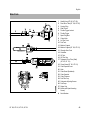
Main Parts
Specifications
Special Accessories
Maintenance and Repairs
STIHL Incorporated Federal
Emission Control Warranty
Statement
Trademarks
40
41
43
45
46
46
47
49
Allow only persons who fully understand
this manual to operate your pole pruner.
To receive maximum performance and
satisfaction from your STIHL pole
pruner, it is important that you read,
understand and follow the safety
precautions and the operating and
maintenance instructions in chapter
"Safety Precautions and Working
Techniques" before using your pole
pruner. For further information you can
go to www.stihlusa.com.
Contact your STIHL dealer or the STIHL
distributor for your area if you do not
understand any of the instructions in this
manual.
Warning!
Because a pole pruner is a high-speed,
fast-cutting power tool with a very long
reach, special safety precautions must
be observed to reduce the risk of personal injury. Careless or improper use
may cause serious or even fatal injury.
33
35
35
36
{
HT 100, HT 101, HT 130, HT 131
1
English
Guide to Using this Manual
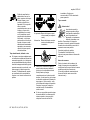
Pictograms
The meanings of the pictograms
attached to or embossed on the
machine are explained in this manual.
Depending on the model concerned, the
following pictograms may be on your
machine.
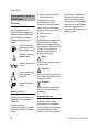
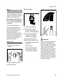
Fuel tank for gasoline
and engine oil mixture
Tank for bar and chain oil
A description of a step or procedure that
refers directly to an illustration may
contain item numbers that appear in the
illustration. Example:
N
Loosen the screw (1).
N
Lever (2) ...
your machine differs from those
described in this manual, please contact
your STIHL dealer for assistance.
In addition to the operating instructions,
this manual may contain paragraphs
that require your special attention. Such
paragraphs are marked with the
symbols and signal words described
below:
Danger!
Indicates an imminent risk of severe or
fatal injury.
Warning!
Direction of chain rotation
Press to operate manual
fuel pump
Manual fuel pump
Indicates a hazardous situation which, if
not avoided, could result in severe or
fatal injury.
Caution!
Indicates a risk of property damage,
including damage to the machine or its
individual components.
Engineering Improvements
Symbols in Text
Many operating and safety instructions
are supported by illustrations.
The individual steps or procedures
described in the manual may be marked
in different ways:
N
2
STIHL’s philosophy is to continually
improve all of its products. As a result,
engineering changes and improvements
are made from time to time. Therefore,
some changes, modifications and
improvements may not be covered in
this manual. If the operating
characteristics or the appearance of
A bullet marks a step or procedure.
HT 100, HT 101, HT 130, HT 131
English
Safety Precautions and
Working Techniques
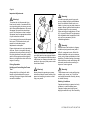
Because a pole pruner is
a high-speed, fast-cutting power tool with a
very long reach, special
safety precautions must
be observed to reduce
the risk of personal injury.
It is important that you
read, fully understand
and observe the following
safety precautions and
warnings. Read the
instruction manual and
the safety precautions
periodically. Careless or
improper use may cause
serious or fatal injury.
Have your STIHL dealer show you how
to operate your power tool. Observe all
applicable local safety regulations,
standards and ordinances.
Warning!
Do not lend or rent your power tool without the instruction manual. Be sure that
anyone using it understands the information contained in this manual.
Warning!
The use of this machine may be hazardous. The pole pruner chain has many
sharp cutters. If the cutters contact your
flesh, they will cut you, even if the chain
is not moving.
Do not cut any material other than wood
or wooden objects. Use your pole pruner
for limbing only.
HT 100, HT 101, HT 130, HT 131
THE OPERATOR
Warning!
Do not use it for other purposes, since
misuse may result in personal injury or
property damage, including damage to
the machine.
Warning!
Minors should never be allowed to use
this power tool. Bystanders, especially
children, and animals should not be
allowed in the area where it is in use.
Warning!
To reduce the risk of injury to bystanders and damage to property, never let
your power tool run unattended. When it
is not in use (e. g. during a work break),
shut it off and make sure that unauthorized persons do not use it.
Most of these safety precautions and
warnings apply to the use of all STIHL
pole pruners. Different models may have
different parts and controls. See the
appropriate section of your instruction
manual for a description of the controls
and the function of the parts of your
model.
Safe use of a pole pruner involves
1.
the operator
2.
the power tool
3.
the use of the power tool.
Physical Condition
You must be in good physical condition
and mental health and not under the
influence of any substance (drugs,
alcohol, etc.) which might impair vision,
dexterity or judgment. Do not operate
this machine when you are fatigued.
Warning!
Be alert – if you get tired, take a break.
Tiredness may result in loss of control.
Working with any power tool can be
strenuous. If you have any condition
that might be aggravated by strenuous
work, check with your doctor before
operating this machine.
Warning!
Prolonged use of a power tool (or other
machines) exposing the operator to
vibrations may produce whitefinger disease (Raynaud's phenomenon) or
carpal tunnel syndrome.
These conditions reduce the hand's
ability to feel and regulate temperature,
produce numbness and burning
sensations and may cause nerve and
circulation damage and tissue necrosis.
All factors which contribute to
whitefinger disease are not known, but
cold weather, smoking and diseases or
physical conditions that affect blood
vessels and blood transport, as well as
high vibration levels and long periods of
exposure to vibration are mentioned as
factors in the development of whitefinger
3
English
disease. In order to reduce the risk of
whitefinger disease and carpal tunnel
syndrome, please note the following:
–
Most STIHL power tools are
available with an anti-vibration
("AV") system designed to reduce
the transmission of vibrations
created by the machine to the
operator's hands. An AV system is
recommended for those persons
using power tools on a regular or
sustained basis.
Warning!
The ignition system of the STIHL unit
produces an electromagnetic field of a
very low intensity. This field may interfere with some pacemakers. To reduce
the risk of serious or fatal injury, persons
with a pacemaker should consult their
physician and the pacemaker manufacturer before operating this tool.
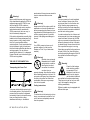
Proper Clothing
–
Wear gloves and keep your hands
warm.
–
Keep the AV system well
maintained. A power tool with loose
components or with damaged or
worn AV elements will tend to have
higher vibration levels.
To reduce the risk of injury, the operator
should wear proper protective apparel.
Maintain a firm grip at all times, but
do not squeeze the handles with
constant, excessive pressure. Take
frequent breaks.
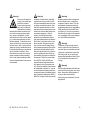
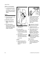
To reduce the risk of
injury to your eyes never
operate your power tool
unless wearing goggles
or properly fitted protective glasses with
adequate top and side protection complying with ANSI Z 87.1 (or your
applicable national standard). To
reduce the risk of injury to your face
STIHL recommends that you also wear
a face shield or face screen over your
goggles or protective glasses.
–
All the above-mentioned precautions do
not guarantee that you will not sustain
whitefinger disease or carpal tunnel
syndrome. Therefore, continual and
regular users should closely monitor the
condition of their hands and fingers. If
any of the above symptoms appear,
seek medical advice immediately.
Warning!
Warning!
Wear an approved safety hard hat to
reduce the risk of injury to your head.
Power tool noise may damage your
hearing. Wear sound barriers (ear plugs
or ear mufflers) to protect your hearing.
Continual and regular users should
have their hearing checked regularly.
4
Be particularly alert and cautious when
wearing hearing protection because
your ability to hear warnings (shouts,
alarms, etc.) is restricted.
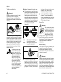
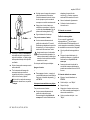
Always wear gloves
when handling the
machine and the cutting
tool. Heavy-duty, nonslip
gloves improve your grip
and help to protect your
hands.
Clothing must be sturdy
and snug-fitting, but allow
complete freedom of
movement. Wear long
pants made of heavy
material to help protect
your legs. Do not wear
shorts, sandals or go
barefoot.
Avoid loose-fitting jackets, scarfs,
neckties, jewelry, flared or cuffed pants,
unconfined long hair or anything that
could become caught on branches,
brush or the moving parts of the unit.
Secure hair so it is above shoulder level.
Good footing is very
important. Wear sturdy
boots with nonslip soles.
Steel-toed safety boots
with cut retardant inserts
are recommended.
THE POWER TOOL
For illustrations and definitions of the
power tool parts see the chapter on
"Main Parts".
HT 100, HT 101, HT 130, HT 131
English
Warning!
Never modify this power tool in any way.
Only attachments supplied by STIHL or
expressly approved by STIHL for use
with the specific STIHL model are
authorized. Although certain unauthorized attachments are useable with
STIHL power tools, their use may, in
fact, be extremely dangerous.
If this tool is subjected to unusually high
loads for which it was not designed (e. g.
heavy impact or a fall), always check
that it is in good condition before
continuing work. Check in particular that
the fuel system is tight (no leaks) and
that the controls and safety devices are
working properly. Do not continue
operating this machine if it is damaged.
In case of doubt, have it checked by your
STIHL servicing dealer.
THE USE OF THE POWER TOOL
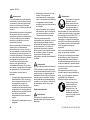
390BA000 KN
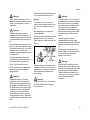
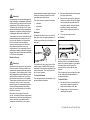
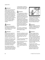
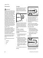
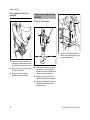
Transporting the Power Tool
This power tool should be carried only in
a horizontal position. Grip the shaft in a
manner that the machine is balanced
horizontally. Keep the hot muffler away
from your body and the cutting
attachment behind you. Accidental
HT 100, HT 101, HT 130, HT 131
acceleration of the engine can cause the
chain to rotate and cause serious
injuries.
Warning!
Always switch off the engine and fit the
scabbard over the cutting attachment
before transporting the power tool over
long distances. When transporting it in a
vehicle, properly secure it to prevent
turnover, fuel spillage and damage to
the unit.
Fuel
Your STIHL power tool uses an oilgasoline mixture for fuel (see the
chapter on "Fuel" of your instruction
manual).
Warning!
Gasoline is an extremely
flammable fuel. If spilled
and ignited by a spark or
other ignition source, it
can cause fire and serious burn injury or
property damage. Use extreme caution
when handling gasoline or fuel mix. Do
not smoke or bring any fire or flame near
the fuel or the power tool. Note that
combustible fuel vapor may escape
from the fuel system.
Fueling Instructions
Warning!
Fuel your power tool in well-ventilated
areas, outdoors. Always shut off the
engine and allow it to cool before refueling. Gasoline vapor pressure may
build up inside the fuel tank depending
on the fuel used, the weather conditions
and the tank venting system.
In order to reduce the risk of burns and
other personal injury from escaping gas
vapor and fumes, remove the fuel filler
cap on your power tool carefully so as to
allow any pressure build-up in the tank
to release slowly. Never remove the fuel
filler cap while the engine is running.
Select bare ground for fueling and move
at least 10 feet (3 m) from the fueling
spot before starting the engine. Wipe off
any spilled fuel before starting your
machine.
Warning!
Check for fuel leakage
while refueling and during operation. If fuel
leakage is found, do not
start or run the engine
until the leak is fixed and
any spilled fuel has been wiped away.
Take care not to get fuel on your clothing. If this happens, change your
clothing immediately.
Different models may be equipped with
different fuel caps.
Warning!
To reduce the risk of serious injury from
burns, never attempt to refuel the unit
until it has been completely removed
from the operator.
5
English
the base of the cap into the correct
position. Then, twist the cap
clockwise, closing it normally.
Misaligned, damaged or broken cap
Toolless cap with grip
N
Warning!
In order to reduce the risk of fuel spillage and fire from an improperly
tightened fuel cap, correctly position
and tighten the fuel cap in the fuel tank
opening.
If the cap does not drop fully into the
opening when the positioning marks
line up and/or if the cap does not
tighten properly when twisted, the
base of the cap may be prematurely
rotated (in relation to the top) to the
closed position. Such misalignment
can result from handling, cleaning
or an improper attempt at
tightening.
N
If your cap still does not tighten
properly, it may be damaged or
broken; immediately stop use of the
unit and take it to your authorized
STIHL dealer for repair.
Screw Cap
Fold the grip flush with
the top of the cap. Grip
the cap and check for
tightness. If the grip does
not lie completely flush
with the cap and the
detent on the grip does
not fit in the corresponding recess in the filler
opening, or if the cap is
loose in the filler opening,
the cap is not properly
seated and tightened and
you must repeat the
above steps.
6
Left:
Right:
Unit vibrations can cause
an improperly tightened
fuel filler cap to loosen or
come off and spill quantities of fuel. In order to
reduce the risk of fuel
spillage and fire, tighten the fuel filler
cap by hand as securely as possible.
See also the "Fueling" chapter in your
Instruction Manual for additional
information.
Base of cap in closed position (with open space)
Base of cap correctly positioned for installation
Before Starting
Take off the chain guard (scabbard) and
inspect the pole pruner for proper
condition and operation. (See the
maintenance chart near the end of the
instruction manual.)
001BA226 KN
To do this with this STIHL cap, raise the
grip on the top of the cap until it is upright
at a 90° angle. Insert the cap in the fuel
tank opening with the raised positioning
marks on the grip of the cap and on the
fuel tank opening lining up. Using the
grip, press the cap down firmly while
turning it clockwise as far as it will go
(approx. 1/4 turn).
001BA227 KN
001BA220 KN
Warning!
N
To return the cap to the open
position for installation, turn the cap
(with the grip up) until it drops fully
into the tank opening. Next, twist the
cap counterclockwise as far as it will
go (approx. 1/4 turn) – this will twist
Warning!
Always check your power tool for proper
condition and operation before starting,
particularly the throttle trigger, throttle
trigger lockout, stop switch and cutting
attachment. The throttle trigger must
move freely and always spring back to
the idle position. Never attempt to modify the controls or safety devices.
HT 100, HT 101, HT 130, HT 131
English
Never operate your power tool if it is
damaged, improperly adjusted or maintained, or not completely or securely
assembled.
Warning!
Check that the spark plug boot is
securely mounted on the spark plug – a
loose boot may cause arcing that could
ignite combustible fumes and cause a
fire.
Keep the handles clean and dry at all
times; it is particularly important to keep
them free of moisture, pitch, oil, fuel mix,
grease or resin in order for you to
maintain a firm grip and properly control
your power tool.
For proper assembly of the bar and
chain follow the procedure described in
the chapter "Mounting the Bar and
Chain" of your instruction manual.
STIHL Oilomatic chain, guide bar and
sprocket must match each other in
gauge and pitch.
Adjust carrying harness and hand grip to
suit your size before starting work.
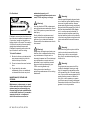
Starting
To reduce the risk of fire and burn
injuries, start the engine at least 10 feet
(3 m) from the fueling spot, outdoors
only.
Start and operate your pole pruner
without assistance.
For specific starting instructions, see the
appropriate section of your manual.
Proper starting methods reduce the risk
of injury.
Place the pole pruner on firm ground or
other solid surface in an open area or, in
the alternative, as shown in the above
picture. Maintain good balance and
secure footing.
Warning!
Proper chain tension is extremely
important. In order to avoid improper
setting, the tensioning procedure must
be followed as described in your manual. Always make sure the hex nut(s) for
the sprocket cover is (are) tightened
securely after tensioning the chain.
Check chain tension once more after
having tightened the nut(s). Never start
the pole pruner with the sprocket cover
loose.
HT 100, HT 101, HT 130, HT 131
Warning!
To reduce the risk of injury from loss of
control be absolutely sure that the guide
bar and chain are clear of you and all
other obstructions and objects, including the ground, because when the
engine starts at starting-throttle, engine
speed will be fast enough for the clutch
to engage the sprocket and turn the
chain.
Once the engine has started,
immediately blip the throttle trigger,
which should release the starting throttle
and allow the engine to slow down to
idle.
With the engine running only at idle,
attach the power tool to the spring hook
of your harness (see appropriate
chapter of this manual).
275BA006 KN
Warning!
Warning!
Warning!
When you pull the starter grip, do not
wrap the starter rope around your hand.
Do not let the grip snap back, but guide
the starter rope to rewind it properly.
Failure to follow this procedure may
result in injury to your hand or fingers
and may damage the starter
mechanism.
To reduce the risk of injury from loss of
control, do not attempt to "drop start"
your power tool.
7
English
Important Adjustments
Warning!
In order to properly control your pole
pruner, always maintain good balance
and a firm foothold. Never work on a
ladder, in a tree or on any other insecure
support. Never hold the machine above
shoulder height. Do not overreach.
When working at a height above 15 feet
(4.5 m) use a lift bucket. For pole pruner
with adjustable shaft, expand the shaft
only as far as necessary for the
intended application.
Warning!
To reduce the risk of personal injury
from loss of control or contact with the
running cutting tool, do not use your unit
with incorrect idle adjustment. At correct
idle speed, the saw chain should not
move. For directions on how to adjust
idle speed, see the appropriate section
of your instruction manual.
Proper chain tension is very important at
all times. Check it at regular intervals
(whenever the pole pruner is shut off). If
the chain becomes loose while cutting,
switch off the engine and then tighten.
Never try to tighten the chain while the
engine is running.
During Operation
Holding and Controlling the Power
Tool
Always hold the unit firmly with both
hands on the handles while you are
working. Wrap your fingers and thumbs
around the handles.
390BA026 KN
If you cannot set the correct idle speed,
have your STIHL dealer check your
power tool and make proper
adjustments and repairs.
Place your left hand on the shaft and
your right hand on rear grip and throttle
trigger. Left-handers should follow these
instructions, too. Keep your hands in this
position to have your pole pruner under
control at all times.
Warning!
Never attempt to operate your power
tool with one hand. Loss of control of the
power tool resulting in serious or fatal
injury may result.
Warning!
Special care must be taken in slippery
conditions (wet ground, snow) and in
difficult, overgrown terrain. Watch for
hidden obstacles such as tree stumps,
roots, rocks, holes and ditches to avoid
stumbling. For better footing, clear away
fallen branches, scrub and cuttings. Be
extremely cautious when working on
slopes or uneven ground.
Warning!
Take extreme care in wet and freezing
weather (rain, snow, ice). Put off the
work when the weather is windy, stormy
or rainfall is heavy.
Working Conditions
Operate and start your power tool only
outdoors in a well-ventilated area.
Operate it under good visibility and
daylight conditions only. Work carefully.
8
HT 100, HT 101, HT 130, HT 131
English
Warning!
As soon as the engine is
running, this product generates toxic exhaust
fumes containing chemicals, such as unburned
hydrocarbons (including
benzene) and carbon monoxide, that
are known to cause respiratory problems, cancer, birth defects, or other
reproductive harm. Some of the gases
(e. g. carbon monoxide) may be colorless and odorless. To reduce the risk of
serious or fatal injury / illness from inhaling toxic fumes, never run the machine
indoors or in poorly ventilated locations.
If exhaust fumes become concentrated
due to insufficient ventilation, clear
obstructions from work area to permit
proper ventilation before proceeding
and / or take frequent breaks to allow
fumes to dissipate before they become
concentrated.
HT 100, HT 101, HT 130, HT 131
Warning!
Inhalation of certain dusts, especially
organic dusts such as mold or pollen,
can cause susceptible persons to have
an allergic or asthmatic reaction. Substantial or repeated inhalation of dust
and other airborne contaminants, in particular those with a smaller particle size,
may cause respiratory or other illnesses. This includes wood dust,
especially from hardwoods, but also
from some softwoods such as Western
Red Cedar. Control dust at the source
where possible. Use good work practices, such as such as always cutting
with a properly sharpened chain (which
produces wood chips rather than fine
dust) and operating the unit so that the
wind or operating process directs any
dust raised by the power tool away from
the operator. Follow the recommendations of EPA / OSHA / NIOSH and
occupational and trade associations
with respect to dust ("particulate matter"). When the inhalation of dust cannot
be substantially controlled, i.e., kept at
or near the ambient (background) level,
the operator and any bystanders should
wear a respirator approved by NIOSH /
MSHA for the type of dust encountered.
Warning!
Breathing asbestos dust is dangerous
and can cause severe or fatal injury,
respiratory illness or cancer. The use
and disposal of asbestos-containing
products have been strictly regulated by
OSHA and the Environmental Protection Agency. If you have any reason to
believe that you might be cutting asbestos, immediately contact your employer
or a local OSHA representative.
Warning!
This power tool has a large range. In
order to reduce the risk of personal or
even fatal injury to bystanders from falling objects or inadvertent contact with
the moving chain of your power tool
always keep bystanders at least 50 feet
(15 m) away when the power tool is
running.
Warning!
Even though bystanders should be kept
away from the running saw, never work
alone. Keep within calling distance of
others in case help is needed.
Stop the engine immediately if you are
approached.
9
English
Operating Instructions
Warning!
Warning!
m
15
t)
0f
(5
Do not operate your power tool using
the starting throttle position, as you do
not have control of the engine speed.
In the event of an emergency, switch off
the engine immediately – move the slide
control / stop switch to 0 or STOP.
15m (50ft)
Warning!
Danger!
Your power tool is not
insulated against electric
shock. To reduce the risk
of electrocution, never
operate this power tool in
the vicinity of any wires or
cables (power, etc.) which may be carrying electric current.
Electricity can jump from one point to
another by means of arcing. Higher
voltage increases the distance electricity
can arc. Electricity can also move
through branches, especially if they are
wet. Maintain a clearance of at least
50 feet (15 m) between the pole pruner
(including any branches it is contacting)
and any electrical line carrying live
current. Before working with less
clearance, contact your electric utility
and make sure the current is turned off.
10
To reduce the risk of cut injuries, keep
hands and feet away from the saw
chain. Never touch a moving chain with
your hand or any other part of your
body. The saw chain continues to move
for a short period after the throttle trigger
is released (inertia effect).
Accelerating the engine while the chain
is blocked increases the load and will
cause the clutch to slip continuously.
This may result in overheating and
damage to important components (e. g.
clutch, polymer housing components) –
which can then increase the risk of injury
from the chain moving while the engine
is idling.
Prior to limbing, clear the working area
from interfering limbs and brush. Then,
establish an escape area away from
where the cut limbs can fall, and remove
all obstacles.
Keep work area clear – move away
fallen limbs. Place all tools and
equipment at a safe distance from the
branches being limbed, but not in the
escape area.
Warning!
Always observe the general condition of
the tree. Look for decay and rot in the
trunk and branches. If it is rotted inside,
it could snap and fall toward the operator while being cut. Also look for broken
or dead branches which could vibrate
loose and fall on the operator. If branch
is thick or heavy, make a shallow relief
cut on the bottom of the branch before
cutting down from the top to help prevent splitting of the branch.
Warning!
If the chain becomes clogged, always
turn off the engine and make sure the
chain has stopped before cleaning.
Make sure that the saw chain does not
touch any foreign materials such as
rocks, fences, nails and the like. Such
objects may be flung off and injure the
operator or bystanders, or damage the
saw chain.
HT 100, HT 101, HT 130, HT 131
English
Warning!
275BA005 KN
Always pull the unit out of the cut with
the chain running to reduce the possibility of pinching the cutting attachment.
Don't put pressure on the pole pruner
when reaching the end of a cut. The
pressure may cause the bar and rotating chain to pop out of the cut or kerf, go
out of control and strike some other
object.
If the bar becomes pinched and caught
in the branch so that the chain can no
longer move, shut off the pole pruner
and carefully move the branch to open
the pinch and release the bar.
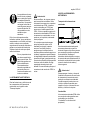
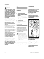
Warning!
Warning!
To reduce the risk of severe or even
fatal injury from falling objects do not cut
vertically above your body. Hold the
pole pruner at an angle of not more than
60° from the horizontal level (see picture). Objects may fall in unexpected
directions. Do not stand directly underneath the limb being cut!
Watch for falling wood! As soon as the
limbed branch starts to fall, step aside
and keep a sufficient distance away from
the falling wood.
HT 100, HT 101, HT 130, HT 131
The muffler and other parts of the
engine (e. g. fins of the cylinder, spark
plug) become hot during operation and
remain hot for a while after stopping the
engine. To reduce risk of burns do not
touch the muffler and other parts while
they are hot.
Warning!
Never modify your muffler. The muffler
could be damaged and cause an
increase in heat radiation or sparks,
thereby increasing the risk of fire and
burn injury. You may also permanently
damage the engine. Have your muffler
serviced and repaired by your STIHL
servicing dealer only.
Catalytic Converter
Warning!
Some STIHL power tools
are equipped with a catalytic converter, which is
designed to reduce the
exhaust emissions of the
engine by a chemical
process in the muffler. Due to this process, the muffler does not cool down as
rapidly as conventional mufflers when
the engine returns to idle or is shut off.
To reduce the risk of fire and burn injuries, the following specific safety
precautions must be observed.
Warning!
To reduce the risk of fire and burn injury,
keep the area around the muffler clean.
Remove excess lubricant and all debris
such as pine needles, branches or
leaves. Let the engine cool down sitting
on concrete, metal, bare ground or solid
wood (e. g. the trunk of a felled tree)
away from any combustible substances.
Warning!
Since a muffler with a catalytic converter
cools down less rapidly than conventional mufflers, always set your power
tool down in the upright position and
never locate it where the muffler is near
dry brush, grass, wood chips or other
combustible materials while it is still hot.
11
English
Your catalytic converter is furnished with
screens designed to reduce the risk of
fire from the emission of hot particles.
Due to the heat from the catalytic
reaction, these screens will normally
stay clean and need no service or
maintenance. If you experience loss of
performance and you suspect a clogged
screen, have your muffler maintained by
a STIHL servicing dealer.
Reactive forces may occur any time the
chain is rotating.The force used to cut
wood can be reversed and work against
the operator. If the rotating chain is suddenly stopped by contact with any solid
object such as a branch or is pinched,
the reactive forces may occur instantly.
These reactive forces may result in loss
of control, which, in turn, may cause
personal injury. An understanding of the
causes of these reactive forces may
help you avoid the element of surprise
and loss of control.
Because of the design of the pole
pruner, the reactive forces experienced
when working with it are generally not as
severe as those encountered with a
chainsaw. Nevertheless, you should
12
Be aware of the location of the guide
bar nose at all times.
2.
Never let the nose of the guide bar
contact any object. Do not cut limbs
with the nose of the guide bar. Be
especially careful near wire fences
and when cutting small, tough
limbs, which may easily catch the
chain.
3.
Cut only one limb at a time.
The most common reactive forces are:
–
kickback,
–
pushback,
–
pull-in.
Kickback
Kickback may occur when the moving
saw chain near the upper quadrant of
the bar nose contacts a solid object or is
pinched.
Reactive Forces
Warning!
1.
The reaction of the cutting force of the
chain causes a rotational force on the
chainsaw in the direction opposite to the
chain movement. This may cause the
bar to move upward.
To Avoid Kickback
The best protection from kickback is to
avoid kickback situations:
A = Pull-in
A
001BA037 KN
An improperly mounted or damaged cylinder housing or a damaged / deformed
muffler shell may interfere with the cooling process of the catalytic converter.
To reduce the risk of fire or burn injury,
do not continue work with a damaged or
improperly mounted cylinder housing or
a damaged / deformed muffler shell.
always maintain a proper grip and good
footing to control the power tool when
you experience such forces.
002BA230 KN
Warning!
Pull-in occurs when the chain on the
bottom of the bar is suddenly stopped
when it is pinched, caught or encounters
a foreign object in the wood. The
reaction of the chain pulls the saw
forward.
Pull-in frequently occurs when the chain
is not rotating at full speed before it
contacts the wood.
To Avoid Pull-in
1.
Be alert to forces or situations that
may cause material to pinch the
chain at the bottom of the bar.
2.
Always start a cut with the chain
rotating at full speed.
HT 100, HT 101, HT 130, HT 131
English
maintained properly or if
nonapproved replacement parts were
used, STIHL may deny coverage.
B = Pushback
B
001BA038 KN
Warning!
Pushback occurs when the chain on the
top of the bar is suddenly stopped when
it is pinched, caught or encounters a
foreign object in the wood. The reaction
of the chain may drive the saw rapidly
straight back toward the operator.
Pushback frequently occurs when the
top of the bar is used for cutting.
Use only identical STIHL replacement
parts for maintenance and repair. Use of
non-STIHL parts may cause serious or
fatal injury.
Strictly follow the maintenance and
repair instructions in the appropriate
sections of your instruction manual.
Please refer to the maintenance chart in
this manual.
Warning!
1.
Be alert to forces or situations that
may cause material to pinch the
chain at the top of the bar.
2.
Do not cut more than one limb at a
time.
Always stop the engine and make sure
that the chain is stopped before doing
any maintenance or repair work or
cleaning the power tool. Do not attempt
any maintenance or repair work not
described in your instruction manual.
Have such work performed by your
STIHL servicing dealer only.
Do not twist the bar when
withdrawing it from an underbuck
cut because the chain can pinch.
Wear gloves when handling or
performing maintenance on the cutting
attachment.
To Avoid Pushback
3.
MAINTENANCE, REPAIR AND
STORING
Maintenance, replacement, or repair
of the emission control devices and
systems may be performed by any
nonroad engine repair establishment
or individual. However, if you make a
warranty claim for a component
which has not been serviced or
HT 100, HT 101, HT 130, HT 131
Warning!
Use the specified spark plug and make
sure it and the ignition lead are always
clean and in good condition. Always
press spark plug boot snugly onto spark
plug terminal of the proper size. (Note: If
terminal has detachable SAE adapter
nut, it must be securely attached.) A
loose connection between spark plug
terminal and the ignition wire connector
in the boot may create arcing that could
ignite combustible fumes and cause a
fire.
Warning!
Never test the ignition system with the
ignition wire boot removed from the
spark plug or with a removed spark
plug, since uncontained sparking may
cause a fire.
Warning!
Do not operate your power tool if the
muffler is damaged, missing or modified. An improperly maintained muffler
will increase the risk of fire and hearing
loss. If your muffler was equipped with a
spark-arresting screen to reduce the
risk of fire, never operate your power
tool if the screen is missing or damaged.
Remember that the risk of forest fires is
greater in hot or dry weather.
13
English
Keep the chain, bar and sprocket clean;
replace worn sprockets or chains. Keep
the chain sharp. You can spot a dull
chain when easy-to-cut wood becomes
hard to cut or burn marks appear on the
wood. Keep chain at proper tension.
Using the Unit
Wear suitable protective clothing,
observe safety precautions.
Tighten all nuts, bolts and screws except
the carburetor adjustment screws after
each use.
N
Adjust telescoping shaft to the
required length (HT 101, HT 131
only).
For maintenance items please also refer
to the maintenance chart in this manual.
N
Starting the engine
N
Put on the shoulder strap.
Store the power tool in a dry and high or
locked location out of reach of children.
Before storing for longer than a few
days, always empty the fuel tank. See
chapter "Storing the machine" in this
manual.
Store fuel and chain oil in approved and
properly labeled safety-type canisters
only. Take care when handling gasoline!
Avoid direct contact with the skin and
avoid inhaling fuel vapor!
Always hold the shaft with your left hand
in the area of the handle hose.
Preparations
N
Do not clean your machine with a
pressure washer. The solid jet of water
may damage parts of the machine.
HT 100, HT 130
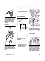
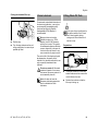
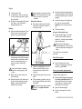
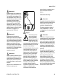
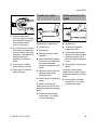
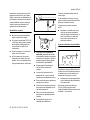
Cutting Sequence
To allow branches a free fall, always cut
the lower branches first. Prune heavy
branches (large diameter) in several
controllable pieces.
Never stand directly underneath
the branch you are cutting – be
wary of falling branches. Note that
a branch may spring back at you
after it hits the ground – risk of
injury.
Disposal
390BA018 KN
Warning!
The shaft should always be held at an
angle of 60° or less.
The least tiring working position is a tool
angle of 60°.
Any lesser angle may be used to suit the
situation concerned.
Do not throw cuttings into the garbage
can – they can be composted.
Working Techniques
Hold the control handle with your right
hand, and the shaft with your left hand.
Your left arm should be extended to the
most comfortable position.
14
HT 100, HT 101, HT 130, HT 131
English
390BA052 KN
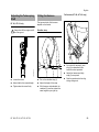
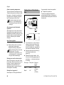
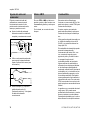
Cross-cut
N
To do this, apply the cutting
attachment and pull it across the
bottom of the branch in an arc as far
as the bar nose.
N
Perform the cross-cut (2) – position
the bar with the hook against the
branch and then perform the crosscut.
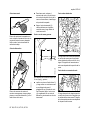
Cutting above obstacles
Flush-cutting thick branches
To avoid pinching the bar in the cut,
position the cutting attachment with the
hook against the branch and then
perform the cross-cut from the top
downwards.
4
390BA020 KN
A
Relieving cut
3
390BA024 KN
2
1
The unit's long reach makes it possible
to prune branches that are overhanging
obstacles, such as rivers or lakes. The
tool angle in this case depends on the
position of the branch.
Cutting from a lift bucket
390BA041 KN
N
To avoid tearing the bark on thick
branches, always start by performing a
relieving cut (1) on the underside of the
branch.
HT 100, HT 101, HT 130, HT 131
perform undercut (3) and then
cross-cut at a distance of about
8 in./20 cm (A) from the final cut.
Then carry out the flush-cut (4),
starting with a relieving cut and
finishing with a cross-cut.
390BA058 KN
If branch diameter is more than
4 in (10 cm), first
The unit's long reach enables cutting to
be performed next to the trunk without
the risk of the lift bucket damaging other
branches. The tool angle in this case
depends on the position of the branch.
15
English
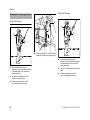
30° angle drive (special accessory)
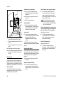
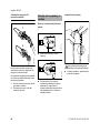
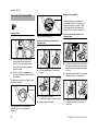
Fitting the chain
Mounting the Bar and
Chain
Removing the chain sprocket cover
390BA042 KN
1
2
390BA003 KN
Unscrew the nut and remove the
cover.
390BA053 KN
N
1
2
The angle drive may be adjusted on the
drive tube to the following positions only:
1
2
16
For cross-cutting vertical branches
and bushes.
For a better view of the cutting
attachment.
N
Wear work gloves to protect your
hands from the sharp cutters.
390BA043 KN
The angle drive keeps the cutting
attachment at an angle of 30° to the
drive tube.
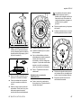
N
Fit the chain – start at the bar nose.
Turn the screw (1)
counterclockwise until the tensioner
slide (2) butts against the left end of
the housing slot, then back it off 5
full turns.
HT 100, HT 101, HT 130, HT 131
English
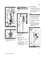
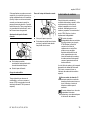
Tensioning the Chain
5
Checking Chain Tension
N
Fit the guide bar over the screw (3)
and engage peg of tensioner slide in
the hole (4) – place the chain over
the sprocket (5) at the same time.
N
Turn the tensioning screw (1)
clockwise until there is very little
chain sag on the underside of the
bar – and the drive link tangs are
engaged in the bar groove.
N
Refit the cover and screw on the nut
fingertight.
N
Go to chapter on "Tensioning the
Saw Chain"
1
Retensioning during cutting work:
N
Stopping the engine
N
Loosen the nut.
N
Hold the bar nose up.
N
Use a screwdriver to turn the
tensioning screw (1) clockwise until
the chain fits snugly against the
underside of the bar.
N
While still holding the bar nose up,
tighten down the nut firmly.
N
Go to "Checking Chain Tension".
A new chain has to be retensioned more
often than one that has been in use for
some time.
N
HT 100, HT 101, HT 130, HT 131
390BA046 KN
3
390BA045 KN
4
390BA044 KN
1
N
Shut off the engine
N
Wear work gloves to protect your
hands.
N
The chain must fit snugly against
the underside of the bar and it must
still be possible to pull the chain
along the bar by hand.
N
If necessary, retension the chain.
A new chain has to be retensioned more
often than one that has been in use for
some time.
N
Check chain tension frequently –
see chapter on "Operating
Instructions".
Check chain tension frequently –
see chapter on "Operating
Instructions".
17
English
Adjusting the Throttle
Cable
4-MIX Engine
A properly adjusted throttle cable is the
precondition for correct operation in the
full throttle, starting throttle and idle
positions.
Adjust the throttle cable only when
the unit is completely and properly
assembled.
002BA163 KN
N
N
Use a suitable tool to push the slide
to the end of the slot (see
illustration).
2
N
18
002BA161 KN
1
Press down the throttle trigger
lockout (1) and squeeze the throttle
trigger (2) (full throttle) – this sets
the throttle cable correctly.
Fuel
The STIHL 4-MIX engine features
mixture lubrication and must be run on a
fuel mixture of gasoline and engine oil.
This engine is certified to operate on
unleaded gasoline and the STIHL twostroke engine oil at a mix ratio of 50:1.
It operates otherwise on the 4-stroke
principle.
Your engine requires a mixture of highquality gasoline and two-stroke air
cooled engine oil.
Use mid-grade unleaded gasoline with a
minimum octane rating of 89 (R+M/2)
and no more than 10% ethanol content.
Fuel with a lower octane rating may
increase engine temperatures. This, in
turn, increases the risk of piston seizure
and damage to the engine.
The chemical composition of the fuel is
also important. Some fuel additives not
only detrimentally affect elastomers
(carburetor diaphragms, oil seals, fuel
lines, etc.), but magnesium castings and
catalytic converters as well. This could
cause running problems or even
damage the engine. For this reason
STIHL recommends that you use only
high-quality unleaded gasoline!
Gasoline with an ethanol content of
more than 10% can cause running
problems and major damage in engines
with a manually adjustable carburetor
and should not be used in such engines.
The ethanol content in gasoline affects
engine running speed – it may be
necessary to readjust the carburetor if
you use fuels with various ethanol
contents.
HT 100, HT 101, HT 130, HT 131
English
If your power tool shows an incorrect
idle adjustment, have your STIHL dealer
check your power tool and make proper
adjustments and repairs.
The idle speed and maximum speed of
the engine change if you switch from a
fuel with a certain ethanol content to
another fuel with a much higher or lower
ethanol content.
This problem can be avoided by always
using fuel with the same ethanol
content.
Use only STIHL two-stroke engine oil or
equivalent high-quality two-stroke
engine oils that are designed for use
only in air cooled two-cycle engines.
We recommend STIHL HP Ultra 2-Cycle
Engine Oil since it is specially
formulated for use in STIHL engines.
Do not use BIA or TCW rated (twostroke water cooled) mix oils or other
mix oils that state they are for use in both
water cooled and air cooled engines
(e.g., outboard motors, snowmobiles,
chain saws, mopeds, etc.).
Take care when handling gasoline.
Avoid direct contact with the skin and
avoid inhaling fuel vapor. When filling at
the pump, first remove the container
from your vehicle and place the
container on the ground before filling. To
reduce the risk of sparks from static
HT 100, HT 101, HT 130, HT 131
Fueling
The container should be kept tightly
closed in order to limit the amount of
moisture that gets into the mixture.
The machine‘s fuel tank should be
cleaned as necessary.
Preparations
Fuel mix ages
Only mix sufficient fuel for a few days
work, not to exceed 3 months of storage.
Store in approved fuel-containers only.
When mixing, pour oil into the container
first, and then add gasoline. Close the
container and shake it vigorously by
hand to ensure proper mixing of the oil
with the fuel.
Gasoline
US gal.
1
2 1/2
5
002BA420 KN
To reduce the risk of personal injury
from loss of control and / or contact with
the running cutting tool, do not use your
unit with incorrect idle adjustment. At
correct idle speed, the cutting tool
should not move.
discharge and resulting fire and/or
explosion, do not fill fuel containers that
are sitting in or on a vehicle or trailer.
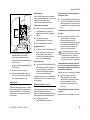
N
Before fueling, clean the filler cap
and the area around it so that dirt
cannot fall into the tank.
N
Always position the machine so that
the filler cap is facing upwards.
Oil (STIHL 50:1 or equivalent high-quality oils)
US fl.oz.
2.6
6.4
12.8
One of two different filler caps is
installed as standard at the factory.
Dispose of empty mixing-oil containers
only at authorized disposal locations.
002BA418 KN
Warning!
Toolless filler cap (with folding grip)
19
English
002BA419 KN
Refueling
Take care not to spill fuel while fueling,
and do not overfill the tank. STIHL
recommends use of the STIHL filling
system (special accessory).
described above must be repeated. See
also the "Toolless cap with grip" section
in the Safety Precautions.
Opening the threaded filler cap
Closing the toolless filler cap
Threaded filler cap
Swing the grip into an upright
position.
N
Turn the cap counterclockwise
(approx. 1/4 turn).
N
Remove the filler cap.
Position the cap with the grip in an
upright position; the raised
positioning marks must line up.
N
Turn cap clockwise as far as it will
go (approx. 1/4 turn).
249BA054 KN
N
N
20
N
Turn the cap counterclockwise until
it can be removed from the tank
opening.
N
Remove the filler cap.
Refueling
Take care not to spill fuel while fueling
and do not overfill the tank. STIHL
recommends use of the STIHL filling
system (special accessory).
249BA056 KN
249BA053 KN
249BA055 KN
200BA421 KN
Opening the toolless filler cap
N
Fold the grip down so that it is flush
with the surface.
If the grip is not flush with the surface
and the lug on the clip does not engage
entirely in the recess (arrow), the cap is
not properly closed and the steps
HT 100, HT 101, HT 130, HT 131
English
Closing the threaded filler cap
200BA422 KN
Chain Lubricant
N
Position cap.
N
Turn the cap clockwise as far as it
will go and tighten it as securely as
possible by hand.
Filling Chain Oil Tank
For automatic and reliable lubrication of
the chain and guide bar – use only an
environmentally compatible quality
chain and bar lubricant. Rapidly
biodegradable STIHL Bioplus is
recommended.
Biological chain oil must be
resistant to aging (e.g. STIHL
Bioplus) since it will otherwise
quickly turn to resin. This results
in hard deposits that are difficult to
remove, especially in the area of
the chain drive and chain. It may
even cause the oil pump to seize.
A full chain oil tank is sufficient for
only half a tankful of fuel. Check
the oil level regularly during
cutting work. Never allow the oil
tank to run dry.
Preparations
Do not use waste oil. Renewed
contact with waste oil can cause
skin cancer. Moreover, waste oil is
environmentally harmful.
Waste oil does not have the
necessary lubricating properties
and is unsuitable for chain
lubrication.
HT 100, HT 101, HT 130, HT 131
390BA047 KN
The service life of the chain and guide
bar depends on the quality of the
lubricant. It is therefore essential to use
only a specially formulated chain
lubricant.
N
Thoroughly clean the oil filler cap
and the area around it to ensure that
no dirt falls into the tank.
N
Position the machine so that the
filler cap is facing up.
21
English
Closing the filler cap
N
N
N
To open the tank, swing the grip to
the vertical position.
To close the oil tank, place the filler
cap in position with the grip upright,
making sure the recesses are in
alignment.
N
Turn the filler cap counterclockwise
as far as stop and remove.
Turn the filler cap clockwise as far
as stop.
N
Fold the grip down so that it is flush
with the top of the cap.
Filling up with chain oil
N
Filling up with chain oil
Take care not to spill chain oil while
refilling and do not overfill the tank.
22
If the oil level in the tank does not go
down, the reason may be a fault in the oil
supply system: Check chain lubrication,
clean the oilways, contact your dealer
for assistance if necessary STIHL
recommends that you have servicing
and repair work carried out exclusively
by an authorized STIHL servicing
dealer.
390BA048 KN
The bayonet-type oil tank filler cap with
hinged grip can be opened and closed
without tools.
Checking Chain
Lubrication
402BA037 KN
402BA036 KN
Opening the filler cap
The saw chain must always throw off a
small amount of oil.
Never operate your saw without
chain lubrication. If the chain runs
dry, the whole cutting attachment
will be irretrievably damaged
within a very short time. Always
check chain lubrication and the oil
level in the tank before starting
work.
Every new chain has to be broken in for
about 2 to 3 minutes.
After breaking in the chain, check chain
tension and adjust if necessary – see
"Checking Chain Tension".
HT 100, HT 101, HT 130, HT 131
English
Adjusting the Telescoping
Shaft
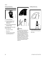
Full harness (HT 100, HT 101 only)
Fitting the Harness
The type and style of the harness
depend on the market.
Always shut off the engine and fit
the chain guard
Shoulder strap
1
1
3
390BA049 KN
390BA040 KN
2
N
Loosen the screw.
N
Put on the shoulder strap (1).
N
Adjust shaft to the required length.
N
Adjust the length of the strap.
N
Tighten down the screw firmly.
N
With the power tool attached, the
carabiner (2) must be at about the
same height as your right hip.
HT 100, HT 101, HT 130, HT 131
2
N
Put on the full harness (1) and
sling (2) as described in the
instruction sheet provided.
N
Adjust the harness and thigh
strap (3) as required.
N
Rest the powerhead in the sling
during cutting work.
386BA012 KN
HT 101, HT 131 only
23
English
HT 101, HT 131 only
Backpack Carrying System
HT 100, HT 130 only
4
1
5
2
1
2
246BA015 KN
N
N
Put the backpack carrying
system (1) on your back and adjust
it as described in the instruction
sheet provided.
N
Attach the carabiner (2) to the
machine's carrying ring.
N
Attach the pole pruner to the
carrying strap when cutting.
24
246BA010 KN
246BA016 KN
3
Adjust the hip belt (3), both shoulder
straps (4) and the carrying strap (5).
N
Put the backpack carrying
system (1) on your back and adjust
it as described in the instruction
sheet provided.
N
Secure the sliding adjuster (2) to the
shaft.
N
Attach the pole pruner to the
carrying strap when cutting.
HT 100, HT 101, HT 130, HT 131
English
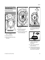
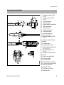
Symbol on slide control
Starting / Stopping the
Engine
4
7
Controls
h – stop symbol and arrow. To stop
the engine, push the slide control in
the direction of the arrow on the stop
symbol (h) to STOP-0.
Starting
5
4
STOP-
7
STOP
Press down the trigger lockout lever
and squeeze the throttle trigger.
N
and hold them in that position.
N
Move the slide control to START
and hold it there.
N
Now release the throttle trigger,
slide control and trigger lockout in
that order. This is the starting
throttle position.
2
Adjust the hip belt (3), both shoulder
straps (4) and the carrying strap (5).
1
N
Squeeze the grips to move the
sliding adjuster up or down the
shaft.
1
2
3
Throttle trigger lockout
Throttle trigger
Slide control
9
8
Positions of slide control
4
5
6
STOP-0 – engine off – the ignition is
switched off
F – normal run position – the engine
is running or can start
START – the ignition is switched on
– the engine can start
249BA007 KN
246BA012 KN
002BA181 KN
N
6
246BA011 KN
3
START
3
5
N
N
HT 100, HT 101, HT 130, HT 131
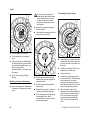
Set the choke knob (8):
25
English
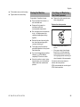
Do not stand or kneel on the drive
tube. This will bend the drive tube
and may result in permanent
damage.
g if the engine is cold
e for warm start – also use this position if the engine has been running
but is still cold.
N
Press the fuel pump bulb (9) at least
five times – even if the bulb is
already filled with fuel.
Alternative method:
N
Starting
N
Remove the blade scabbard. Check
that the chain is not touching the
ground or any other obstacles.
Place the unit on the ground: It must
rest securely on the engine support
and the hook. If necessary, rest the
hook on a raised support (e.g. a
branch, mound or something
similar).
Check that nobody is standing
within the working range of the
pruner.
N
Crank the engine until it begins to
fire. After no more than five
attempts, turn the choke knob to
e.
N
Continue cranking.
As soon as the engine runs
N
Blip the throttle trigger. The slide
control moves to the normal run
position F – and the engine settles
down to idle speed.
Make sure the carburetor is
correctly adjusted. The saw chain
must not rotate when the engine is
idling.
Your machine is now ready for
operation.
Shut off the engine.
N
N
Hold the unit firmly with your left
hand on the fan housing – your
thumb should be under the fan
housing.
N
Make sure you have a safe and
secure footing.
N
Hold the starter grip with your right
hand.
N
Hold the unit with your left hand on
the fan housing and press it down
firmly – your thumb should be
under the fan housing.
N
Pull the starter grip slowly until you
feel it engage and then give it a brisk
strong pull.
26
Do not let the starter grip snap back.
Guide it slowly back into the housing
so that the starter rope can rewind
properly.
Remove the chain guard. Position
the shaft on a branch so that it is
held by the hook.
390BA033 LA
N
N
Do not pull out the starter rope all
the way – it might otherwise
break.
Push the slide control in the
direction of the arrow on the stop
symbol (h) to STOP-0.
At very low outside temperatures:
As soon as the engine runs:
N
Blip the throttle trigger to disengage
the starting throttle position. The
slide control moves to the normal
run position (F) – and the engine
settles down to idle speed.
N
Open the throttle slightly.
N
Warm up the engine for a short
period.
HT 100, HT 101, HT 130, HT 131
English
If the engine does not start
Fuel tank run until completely dry
N
After refueling, press the fuel pump
bulb at least five times – even if the
bulb is filled with fuel.
N
Set the choke knob according to
engine temperature.
N
Start the engine.
Choke knob
If you did not turn the choke knob to e
quickly enough after the engine began to
fire, the combustion chamber is flooded.
N
Turn the choke knob to e.
N
Set the slide control, lockout lever
and throttle trigger to the starting
throttle position.
N
Start the engine by pulling the
starter rope briskly – 10 to 20 pulls
may be necessary.
If the engine still does not start
N
Move the slide control to STOP-0.
N
Remove the spark plug – see
"Spark Plug".
N
Dry the spark plug.
N
Crank the engine several times with
the starter to clear the combustion
chamber.
N
Refit the spark plug – see "Spark
Plug".
N
Move the slide control to START.
N
Set the choke knob to e – even if
the engine is cold.
N
Now start the engine.
Throttle cable adjustment
N
Check adjustment of throttle cable –
see chapter on "Adjusting the
Throttle Cable".
HT 100, HT 101, HT 130, HT 131
Operating Instructions
During break-in period
A factory-new machine should not be
run at high revs (full throttle off load) for
the first three tank fillings. This avoids
unnecessary high loads during the
break-in period. As all moving parts
have to bed in during the break-in
period, the frictional resistances in the
engine are greater during this period.
The engine develops its maximum
power after about 5 to 15 tank fillings.
During Operation
Do not make the mixture leaner to
achieve an apparent increase in
power – this could damage the
engine – see "Adjusting the
Carburetor".
Check chain tension frequently
A new chain has to be retensioned more
often than one that has been in use for
some time.
Chain cold
Tension is correct when the chain fits
snugly against the underside of the bar
and can still be pulled along the bar by
hand. Retension if necessary – see
"Tensioning the Saw Chain".
27
English
Chain at operating temperature
The chain stretches and begins to sag.
The drive links must not come out of the
bar groove – the chain may otherwise
jump off the bar. Retension the chain –
see "Tensioning the Saw Chain".
If groove depth is less than specified:
Taking Care of the Guide
Bar
N
The drive link tangs will otherwise
scrape along the bottom of the groove –
the cutters and tie straps will not ride on
the bar rails.
2
The chain contracts as it cools
down. If it is not slackened off, it
can damage the gear shaft and
bearings.
Replace the guide bar.
Allow engine to run for a short while at
idle speed so that engine heat can be
dissipated by the flow of cooling air. This
protects engine-mounted components
(ignition, carburetor) from thermal
overload.
1
3
After Finishing Work
N
Storing your saw for a short period
Wait for the engine to cool down. Drain
the fuel tank. Store the machine in a dry
location. Check the tightness of all
accessible screws and nuts (not
adjusting screws) at regular intervals
and retighten if necessary.
Storing for a long period
See chapter on "Storing the Machine"
28
N
Turn the bar over – every time you
sharpen the chain and every time
you replace the chain – this helps
avoid one-sided wear, especially at
the nose and underside of the bar.
N
Regularly clean the oil inlet hole (1),
the oilway (2) and the bar
groove (3).
N
Measure the groove depth – with
the scale on the filing gauge (special
accessory) – in the area used most
for cutting.
Slacken off the chain if you have
retensioned it at operating
temperature during cutting work.
Always slacken off the chain after
finishing work. The chain
contracts as it cools down. If it is
not slackened off, it can damage
the gear shaft and bearings.
390BA050 KN
After long period of full-throttle
operation
Chain type
Picco
Rapid
Chain pitch Minimum
groove
depth
3/8" P
0.20"
(5.0 mm)
1/4"
0.16"
(4.0 mm)
HT 100, HT 101, HT 130, HT 131
English
Cleaning the Air Filter
Engine Management
If there is a noticeable loss of engine
power
4
2
273BA006 KN
1
N
Turn the choke knob to g
N
Take out the screw (1) and remove
the filter cover (2).
N
Clean away loose dirt from around
the filter.
N
Grip the filter element (3) at the
cutout (arrow) in the filter
housing (4) and remove it.
N
Fit a new filter element. As a
temporary measure you can knock it
out on the palm of your hand or blow
it out with compressed air. Do not
wash.
N
Replace damaged parts.
Exhaust emissions are controlled by the
design of the fundamental engine
parameters and components (e.g.
carburation, ignition, timing and valve or
port timing) without the addition of any
major hardware.
Adjusting the Carburetor
The carburetor comes from the factory
with a standard setting.
This setting provides an optimum fuel-air
mixture under most operating
conditions.
With this carburetor it is only possible to
adjust the high speed and low speed
screws within fine limits.
Standard Setting
N
Stopping the engine
N
Check chain tension
N
Check the air filter and clean or
replace as necessary.
N
Check that the throttle cable is
properly adjusted – readjust if
necessary – see chapter on
"Adjusting the Throttle Cable".
N
Check the spark arresting screen
(not in all versions) and clean or
replace as necessary.
Installing the filter
N
Install the filter element in the filter
housing and fit the cover.
N
Insert the screw and tighten it down
firmly.
HT 100, HT 101, HT 130, HT 131
29
English
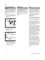
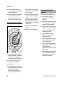
Conditions for adjustment
H
3/4
L
3/4
N
Carry out the standard setting
without disturbing the high speed
screw (H).
N
Warm up the engine for about 3
minutes.
N
Open the throttle wide.
Chain rotates when engine is idling
N
If the chain continues moving
when the engine is idling, have
your saw machine and repaired by
your servicing dealer.
At high altitude
N
249BA032 KN
LA
N
Carefully turn both adjusting screws
counterclockwise as far as stop:
–
The high speed screw (H) is 3/4 turn
open.
–
The low speed screw (L) is 3/4 turn
open.
N
Start and warm up the engine.
N
Adjust idle speed with the idle speed
screw (LA) so that the chain does
not run.
Fine Tuning
At sea level
N
Rule of thumb:
Turn the high speed screw (H) about
one quarter of a turn for every 1000 m
(3300 ft) change in altitude.
30
Turn the high speed screw (H)
counterclockwise (richer), no further
than stop, until there is no
noticeable increase in engine
speed.
It is possible that maximum engine
speed may be reached with the standard
setting.
Adjusting Idle Speed
Erratic idling behavior, engine stops
even though setting of LA-screw has
been corrected, poor acceleration
Idle setting is too lean
N
Turn the low speed screw (L)
counterclockwise, no further than
stop, until the engine runs and
accelerates smoothly.
Erratic idling behavior
Idle setting is too rich
N
Turn the low speed screw (L)
clockwise, no further than stop, until
the engine runs and accelerates
smoothly.
It is usually necessary to change the
setting of the idle speed screw (LA) after
every correction to the low speed
screw (L).
N
A slight correction of the setting of the
high speed screw (H) may be necessary
if engine power is not satisfactory when
operating at high altitude or at sea level.
Turn the high speed screw (H)
clockwise (leaner), no further than
stop, until there is no noticeable
increase in engine speed.
Turn the idle speed screw (LA)
counterclockwise until the chain
stops rotating and then turn the
screw about another 1/2 to 3/4 turn
in the same direction.
Warm up the engine for about 3
minutes.
Engine stops while idling
N
Turn the idle speed screw (LA)
slowly clockwise until the engine
runs smoothly – the chain must not
rotate.
HT 100, HT 101, HT 130, HT 131
English
Spark Arresting Screen in
Muffler
If the engine is down on power, check
the spark arresting screen in the muffler.
N
Lift the spark arresting screen (5)
and pull it out.
N
Clean the spark arresting screen. If
the screen is damaged or heavily
carbonized, fit a new one.
N
Wait for the muffler to cool down.
N
Refit the spark arresting screen.
N
Move the slide control to STOP-0.
N
Insert the screw and tighten it down
firmly.
N
Fit the shroud.
249BA059 KN
1
N
Take out the screw (1).
Spark Plug
If engine is down on power, difficult to
start or runs poorly at idling speed, first
check the spark plug.
Fit a new spark plug after approx. 100
operating hours or earlier if the
electrodes are badly eroded.
Wrong fuel mix (too much engine oil in
the gasoline), a dirty air filter and
unfavorable running conditions (mostly
at part throttle etc.) affect the condition
of the spark plug. These factors cause
deposits to form on the insulator nose
which may result in trouble in operation.
Removing the spark plug
2
N
N
2
Move the slide control to STOP-0.
1
249BA063 KN
3
249BA060 KN
N
Take out the screws (2) and remove
the shroud (3).
N
Pull off the spark plug boot (1).
N
Unscrew the spark plug.
Take out the screw (4).
HT 100, HT 101, HT 130, HT 131
31
English
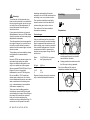
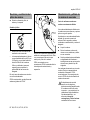
Checking the Spark Plug
Installing the spark plug
Clean dirty spark plug.
N
Check electrode gap (A) and
readjust if necessary – see
"Specifications".
N
Use only resistor type spark plugs of
the approved range.
Rectify problems which have caused
fouling of spark plug:
–
Too much oil in fuel mix.
–
Dirty air filter.
–
Unfavorable running conditions,
e.g. operating at part load.
32
2
3
002BA178 KN
N
2
002BA363 KN
A
000BA039 KN
1
Warning!
To reduce the risk of fire and burn injury,
use only spark plugs authorized by
STIHL. Always press spark plug boot (1)
snugly onto spark plug terminal (2) of
the proper size. (Note: If terminal has
detachable SAE adapter nut, it must be
attached.) A loose connection between
spark plug boot and ignition wire connector in the boot may create arcing that
could ignite combustible fumes and
cause a fire.
N
Screw the spark plug (3) into the
cylinder and fit the boot (2) (press it
down firmly).
HT 100, HT 101, HT 130, HT 131
English
Replacing the Starter Rope
and Rewind Spring
Replacing the Starter Rope
6
3
4
5
1
N
Push the slide control in direction of
arrow h – to STOP-0.
N
Take out the screws (1).
N
Remove the starter cover (2) from
the housing.
HT 100, HT 101, HT 130, HT 131
N
Ease the spring clip (3) off the
starter post.
N
Remove the rope rotor with
washer (4) and pawl (5).
N
Remove the remaining rope from
the rotor and starter grip.
N
Tie a simple overhand knot in the
new rope and then thread it through
the top of the grip and the rope
bushing (6).
N
Thread the rope through the rotor
and secure it with a simple
overhand knot.
N
Coat the rope rotor bearing bore
with non-resinous oil.
N
Slip the rotor over the starter post –
turn it back and forth to engage the
anchor loop of the rewind spring.
249BA015 KN
1
249BA061 KN
2
249BA014 KN
249BA013 KN
1
33
English
The bits of spring may still be
under tension and could fly apart
when you take them out of the
housing. To reduce the risk of
injury, wear face protection and
work gloves.
3
4
Remove the spring housing and
pieces of spring.
N
Lubricate the new spring with a few
drops of non-resinous oil.
Refit the pawl (5) in the rotor.
N
Fit the washer (4) on the starter
post.
N
Use a screwdriver or suitable pliers
to fit the spring clip (3) on the starter
post and over the pawl's peg – the
spring clip must point
counterclockwise – as shown in the
illustration.
N
Go to "Tensioning the Rewind
Spring".
249BA018 KN
N
249BA016 KN
249BA013 KN
5
N
Tensioning the rewind spring
N
Position the new spring housing,
bottom plate facing up, against the
cutouts (arrows).
N
Push the spring housing into the
starter cover.
N
Reinstall the rope rotor – then go to
"Tensioning the Rewind Spring".
N
If the spring pops out of the spring
housing and uncoils: Refit it
counterclockwise, starting outside
and working inwards.
Replacing a broken rewind spring
N
34
Remove the rope rotor as described
in chapter on "Replacing the starter
rope".
N
Make a loop in the unwound starter
rope and use it to turn the rope rotor
six full revolutions in the direction of
the arrow.
N
Hold the rotor steady. Pull out and
straighten the twisted rope.
N
Let go of the rotor.
N
Release the rope slowly so that it
winds onto the rotor. The starter grip
must locate firmly in the rope
bushing. If the grip droops to one
side: Add one more turn on the rope
rotor to increase spring tension.
N
When the starter rope is fully
extended it must still be possible to
rotate the rotor another half turn. If
this is not the case, the spring is
overtensioned and could break.
Take one turn of the rope off the
rotor.
HT 100, HT 101, HT 130, HT 131
English
Fit the starter cover on the housing.
N
Tighten down the screws firmly.
Storing the Machine
For periods of 3 months or longer
HT 100, HT 101, HT 130, HT 131
N
Drain and clean the fuel tank in a
well ventilated area.
N
Dispose of fuel properly in
accordance with local
environmental requirements.
N
Run the engine until the carburetor
is dry – this helps prevent the
carburetor diaphragms sticking
together.
N
Remove the saw chain and guide
bar, clean them and spray with
corrosion inhibiting oil.
N
Thoroughly clean the machine –
pay special attention to the cylinder
fins and air filter.
N
If you use a biological chain and bar
lubricant, e.g. STIHL BioPlus,
completely fill the chain oil tank.
N
Store the machine in a dry, high or
locked location, out of the reach of
children and other unauthorized
persons.
Checking and Replacing
the Chain Sprocket
N
Remove the chain sprocket cover,
chain and guide bar.
Replace the chain sprocket
a
000BA054 KN
N
–
after using two saw chains or
sooner
–
if the wear marks (a) are deeper
than 0.02 in (0.5 mm) since this
would reduce the life of the chain.
Use a gauge (special accessory) to
check the depth of the wear marks.
It is best to use two saw chains in
rotation with one sprocket.
STIHL recommends the use of original
STIHL chain sprockets.
35
English
Maintaining and
Sharpening the Saw Chain
Chain Pitch
Cutting effortlessly with a correctly
sharpened chain
a
The chain sprocket is driven via a friction
clutch. Have the chain sprocket replaced
by a servicing dealer.
STIHL recommends that you have
servicing and repair work carried out
exclusively by an authorized STIHL
servicing dealer.
N
Clean the chain.
N
Check the chain for cracks in the
links and damaged rivets.
N
Replace any damaged or worn
parts of the chain and match the
new parts to the shape and size of
the original parts.
Carbide-tipped saw chains (Duro) are
particularly wear resistant. STIHL
recommends you have your chain
resharpened by a STIHL servicing
dealer.
It is absolutely essential to comply
with the angles and dimensions
specified below. If the saw chain is
incorrectly sharpened – and in
particular if the depth gauge is set
too low – there is an increased
risk of kickback, with resulting risk
of injury.
The saw chain cannot be locked in place
on the guide bar. Therefore, it is best to
remove the chain from the bar and
resharpen it on a workshop sharpening
tool (FG 2, HOS, USG).
36
The chain pitch (a) is marked on the
depth gauge end of each cutter.
Mark (a)
7
1 or 1/4
6, P or PM
2 or 325
3 or 3/8
Chain Pitch
inch
mm
1/4 P
6,35
1/4
6,35
3/8 P
9,32
0.325
8,25
3/8
9,32
Select file diameter according to chain
pitch – see table “Sharpening Tools”.
You must observe certain angles when
resharpening the chain cutter.
Filing and side plate angles
A
B
A
689BA021 KN
Do not work with a dull or damaged
chain as it will increase the physical
effort required, produce unsatisfactory
results and a higher rate of wear.
689BA027 KN
A properly sharpened chain slices
through wood effortlessly and requires
very little feed pressure.
Filing angle
HT 100, HT 101, HT 130, HT 131
English
B
Side plate angle
The correct side plate angle is obtained
automatically if you use the prescribed
file holder and file diameter.
Angle (°)
A
B
Micro = semi-chisel chain, 30
75
e.g. 63 PMC3, 26 RMC3,
36 RMC
Super = full chisel chain, 30
60
e.g. 63 PS3, 26 RSC,
36 RSC3
Ripping chain, e.g.
10
75
63 PMX, 36 RMX
A file holder must be used for manual
resharpening (see table "Sharpening
Tools"). The correct filing angles are
marked on the file holder.
N
Clamp the bar in a vise if necessary.
N
Sharpen the chain frequently, take
away as little metal as possible –
two or three strokes of the file are
usually enough.
Use only special saw chain
sharpening files. Other files have the
wrong shape and cut.
For checking angles
Cutter shapes
The angles must be the same on all
cutters. If the angles are uneven: Chain
will run roughly, not in a straight line,
wear quickly and finally break.
File holder
Use a STlHL filing gauge (special
accessory, see table "Sharpening
Tools"). This is a universal tool for
checking the filing and side plate angles,
depth gauge setting, cutter length and
groove depth. It also cleans the guide
bar groove and oil inlet holes.
689BA043 KN
001BA203 KN
90°
N
Hold the file horizontally (at a right
angle to the side of the guide bar)
and file according to the angles
marked on the file holder. Rest the
file holder on the top plate and depth
gauge.
689BA025 KN
File correctly
N
Use a file holder
HT 100, HT 101, HT 130, HT 131
689BA018 KN
STIHL saw chains are sharpened to a
filing angle of 30°. Exceptions are
ripping chains with a filing angle of 10°.
Ripping chains have an X in their
designations.
N
Select sharpening tools according
to chain pitch.
N
Always file from the inside to the
outside of the cutter.
N
If you use an FG 2, HOS or USG
sharpener: Remove the chain from
the bar and sharpen according to
the instructions supplied with the
tool.
N
The file only sharpens on the
forward stroke – lift the file off the
cutter on the backstroke.
N
Avoid touching the tie straps and
drive links with the file.
N
Rotate the file at regular intervals
while filing to avoid one-sided wear.
37
English
Use a piece of hardwood to remove
burrs from the cutting edge.
Chain Pitch
N
Check angles with the filing gauge.
inch
1/4 P
1/4
3/8 P
0.325
3/8
N
Find the shortest cutter and then file
all other cutters back to the same
length. It is best to have this work
done by a servicing dealer on an
electric grinder.
Depth gauge setting
This setting may be increased by
0.2 mm (0.008") for cutting softwood in
the mild weather season – no frost.
1
N
2
The kickback tendency of the
machine is increased if the depth
gauges are too low.
Place a filing gauge (1) that
matches the chain pitch on the
chain and press it against the cutter
– if the depth gauge projects from
the filing gauge, the depth gauge
has to be lowered.
Saw chains with humped drive link (2) –
upper part of humped drive link (2) (with
service mark) is lowered along with the
depth gauge.
The other parts of the humped
drive link must not be filed since
this may increase the kickback
tendency of the power tool.
38
File the top of the depth gauge
parallel to the stamped service
marking (see arrow) – but do not
lower the highest point of the depth
gauge in this process.
Use a filing gauge to check the
setting every time you sharpen the
chain.
689BA061 KN
689BA023 KN
Specified distance or setting
between depth gauge and cutting
edge.
N
The depth gauge setting is reduced
when the chain is sharpened.
a
a
File down the depth gauge until it is
level with the filing gauge.
Lowering depth gauges
N
The depth gauge determines the height
at which the cutter enters the wood and
thus the thickness of the chip removed.
N
689BA044 KN
If the cutters are not the same length,
they will have different heights. This
makes the chain run roughly and can
cause it to break.
(mm)
(6,35)
(6,35)
(9,32)
(8,25)
(9,32)
689BA052 KN
All cutters must be the same length.
Depth gauge
setting (a)
mm
(inch)
0,45
(0.018)
0,65
(0.026)
0,65
(0.026)
0,65
(0.026)
0,65
(0.026)
689BA051 KN
N
N
Place the filing gauge on the chain –
the highest point of the depth gauge
must be level with the filing gauge.
HT 100, HT 101, HT 130, HT 131
English
N
After sharpening, clean the chain
thoroughly, remove filings or
grinding dust – lubricate the chain
thoroughly.
N
Before a long out-of-service period,
clean the chain and store it in a welloiled condition.
Sharpening Tools (special accessories)
Chain Pitch
Round file ^ Round file
File holder
inch
(mm)
mm (inch)
Part No.
Part No.
1/4 P
(6,35) 3,2 (1/8)
5605 771 3206
5605 750 4300
1/4
(6,35) 4,0 (5/32)
5605 772 4006
5605 750 4327
3/8 P
(9,32) 4,0 (5/32)
5605 772 4006
5605 750 4327
0.325
(8,25) 4,8 (3/16)
5605 772 4806
5605 750 4328
3/8
(9,32) 5,2 (13/64) 5605 772 5206
5605 750 4329
1) consisting of file holder with round file, flat file and filing gauge
HT 100, HT 101, HT 130, HT 131
Filing gauge
Part No.
0000 893 4005
1110 893 4000
1110 893 4000
1110 893 4000
1110 893 4000
Flat file
Part No.
0814 252 3356
0814 252 3356
0814 252 3356
0814 252 3356
0814 252 3356
Sharpening kit 1)
Part No.
--5605 007 1027
5605 007 1027
5605 007 1028
5605 007 1029
39
English
Inspections and
Maintenance by Dealer
Fuel pickup body in tank
N
Have the pickup body in the fuel
tank replaced every year.
STIHL recommends that you have
servicing and repair work carried out
exclusively by an authorized STIHL
servicing dealer.
40
HT 100, HT 101, HT 130, HT 131
English
Complete machine
Control handle
Air filter
Pickup body in fuel tank
Visual inspection (condition, leaks)
X
Clean
Check operation
X
X
X
Replace
X
Check
Carburetor
Check idle adjustment – chain must not
rotate
X
X
X
X
Cooling inlets
X
X
X
Readjust idle
Spark plug
X
X
Replace
Clean
if required
X
X
Clean
Fuel tank
if damaged
if problem
every 12 months
monthly
weekly
after each refueling stop
before starting work
The following intervals apply to normal operating conditions only. If your daily working time is longer or operating conditions are difficult (very dusty work area, etc.),
shorten the specified intervals accordingly.
after finishing work or daily
Maintenance and Care
X
Adjust electrode gap
X
Replace after every 100 operating hours
Visual inspection
X
Clean
X
Valve clearance
Check and, if necessary, have adjusted
by dealer after first 139 hours of
operation1)
X
Combustion chamber
Decoke after first 139 hours of operation, then every 150 hours of operation
X
Spark arresting screen in muffler
Check
X
X
Clean or replace
X
All accessible screws and nuts (not adjustRetighten
ing screws)
Antivibration elements
HT 100, HT 101, HT 130, HT 131
Check
Have replaced by dealer1)
X
X
X
X
X
X
41
Chain lubrication
Saw chain
Check
X
Inspect, also check sharpness
X
X
Check chain tension
X
X
Sharpen
Check (wear, damage)
Guide bar
X
X
Clean and turn over
X
Deburr
X
Replace
Chain sprocket
Safety labels
1)
42
Check
X
X
X
X
Have replaced by dealer1)
Replace
if required
if damaged
if problem
every 12 months
monthly
weekly
after each refueling stop
before starting work
The following intervals apply to normal operating conditions only. If your daily working time is longer or operating conditions are difficult (very dusty work area, etc.),
shorten the specified intervals accordingly.
after finishing work or daily
English
X
X
STIHL recommends a STIHL servicing dealer.
HT 100, HT 101, HT 130, HT 131
English
Main Parts
1
2
3
4
5
6
7
8
9
10
11
12
13
14
15
16
17
18
19
20
21
22
23
24
25
26
27
28
#
HT 100, HT 101, HT 130, HT 131
Handle Hose (HT 100, HT 130)
Fixed Drive Tube (HT 100, HT 130)
Carrying Ring
Slide Control
Throttle Trigger Lockout
Throttle Trigger
Spark Plug Boot
Choke Knob
Air Filter Cover
Fuel Tank
Machine Support
Machine Support (HT 130, HT 131)
Oilomatic Saw Chain
Guide Bar
Oil Tank
Oil Filler Cap
Telescopic Drive Tube (Shaft)
(HT 101, HT 131)
Clamp Screw (HT 101, HT 131)
Chain Sprocket Cover
Hook
Chain Guard (Scabbard)
Chain Sprocket
Chain Tensioner
Fuel Filler Cap
Carburetor Adjusting Screws
Fuel Pump
Starter Grip
Muffler (with Spark Arresting
Screen)
Serial Number
43
English
Definitions
1
2
Handle Hose (HT 100, HT 130)
For holding and controlling the unit
with the hand during operation.
Fixed Drive Tube (HT 100,
HT 130)
Encloses and protects the drive
shaft between the engine and
gearbox.
12 Machine Support (HT 130,
HT 131)
For resting machine on the ground.
13 Oilomatic Saw Chain
A loop consisting of cutters, tie
straps and drive links.
14 Guide Bar
Supports and guides the saw chain.
15 Oil Tank
Tank for chain lubricating oil.
3
Carrying Ring
Connects the unit to the harness.
4
Slide Control
For starting throttle, run and stop.
Keeps the choke partially open
during starting and switches off the
ignition to stop the engine.
5
Throttle Trigger Lockout
Must be depressed before the
throttle trigger can be activated.
18 Clamp Screw (HT 101, HT 131)
For adjusting the length of the
telescopic drive tube.
6
Throttle Trigger
Controls the speed of the engine.
7
Spark Plug Boot
Connects the spark plug with the
ignition lead.
19 Chain Sprocket Cover
Covers the clutch and chain
sprocket.
8
Choke Knob
Eases engine starting by enriching
mixture.
9
Air Filter Cover
Covers and protects the air filter
element.
10 Fuel Tank
For fuel and oil mixture.
11 Machine Support
For resting machine on the ground.
44
16 Oil Filler Cap
For closing the oil tank.
17 Telescopic Drive Tube (Shaft)
(HT 101, HT 131)
Adjustable drive tube enables user
to optimize machine's reach.
25 Carburetor Adjusting Screws
For tuning the carburetor.
26 Fuel Pump
Provides additional fuel feed for a
cold start.
27 Starter Grip
The grip of the pull starter, for
starting the engine.
28 Muffler (with Spark Arresting
Screen)
Muffler reduces exhaust noises and
diverts exhaust gases away from
operator.
Spark arresting screen is designed
to reduce the risk of fire.
20 Hook
For hooking the machine to a
branch and pulling branches away.
21 Chain Guard (Scabbard)
To protect the operator from
touching the chain.
22 Chain Sprocket
The toothed wheel that drives the
saw chain.
23 Chain Tensioner
Permits precise adjustment of chain
tension.
24 Fuel Filler Cap
For closing the fuel tank.
HT 100, HT 101, HT 130, HT 131
English
Specifications
Bore:
Stroke:
Engine power to
ISO 8893:
EPA / CEPA
The Emission Compliance Period
referred to on the Emissions
Compliance Label indicates the number
of operating hours for which the engine
has been shown to meet Federal
emission requirements.
Category
A = 300 hours
B = 125 hours
C = 50 hours
HT 130, HT 131
Engine
Displacement:
Single cylinder four-stroke engine with
mixture lubrication
HT 100, HT 101
Displacement:
1.57 in. (40 mm)
0.98 in. (25 mm)
1.40 hp
(1.05 kW)
at 7,000 rpm
Idle speed:
2,800 rpm
Cut-off speed (rated): 10,500 rpm
Max. output shaft
speed (chain
sprocket):
8,290 rpm
Valve clearance
Inlet valve:
0.004 in.
(0.10 mm)
Exhaust valve:
0.004 in.
(0.10 mm)
1.92 cu.in
(31.4 cm3)
2.22 cu.in
(36.3 cm3)
Bore:
1.69 in (43 mm)
Stroke:
0.98 in. (25 mm)
Engine power to
1.90 hp (1.4 kW)
ISO 8893:
at 8,500 rpm
Idle speed:
2,800 rpm
Cut-off speed (rated): 10,500 rpm
Max. output shaft
speed (chain
sprocket):
10,500 rpm
Valve clearance
Inlet valve:
0.004 in.
(0.10 mm)
Exhaust valve:
0.004 in.
(0.10 mm)
HT 100, HT 101
Spark plug (resistor
type):
Electrode gap:
Bosch USR 7AC
0.02 in. (0.5 mm)
HT 130, HT 131
Spark plug (resistor
type):
Electrode gap:
NKG CMR 6H
0.02 in. (0.5 mm)
Chain lubrication
Fully automatic, speed-controlled oil
pump with rotary piston
Oil tank capacity:
7.4 fl.oz (0.22 L)
Fuel System
All position diaphragm carburetor with
integral fuel pump
Fuel tank capacity: 17.9 fl.oz (0.50 L)
Weight
dry, without bar and chain
HT 100:
12.1 lbs (5.5 kg)
HT 101:
16.8 lbs (7.6 kg)
HT 130:
12.6 lbs (5.7 kg)
HT 131:
17.2 lbs (7.8 kg)
Ignition System
Electronic magneto ignition
HT 100, HT 101, HT 130, HT 131
45
English
Cutting Attachment
Rollomatic guide bars
Reduced kickback STIHL guide bar
(with green label)
Cutting length:
12 in. (30 cm)
Pitch:
3/8" P (9.32 mm)
Groove width:
0.043" (1.1 mm)
Nose sprocket:
7-teeth
3/8" Picco chain
Reduced kickback STIHL saw chain
(with green label)
Picco Micro Mini Comfort 3
(61 PMMC3)
Pitch:
3/8" P (9.32 mm)
Drive link gauge: 0.043" (1.1 mm)
Special Accessories
Contact your STIHL dealer for
information regarding special
accessories that may be available for
your product.
Maintenance and Repairs
Users of this unit should carry out only
the maintenance operations described
in this manual. Other repair work may be
performed only by authorized STIHL
service shops.
Warranty claims following repairs can be
accepted only if the repair has been
performed by an authorized STIHL
servicing dealer using original STIHL
replacement parts.
Original STIHL parts can be identified by
the STIHL part number, the {
logo and, in some cases, by the STIHL
parts symbol K. The symbol may
appear alone on small parts.
Chain sprocket
6-tooth for 3/8" P (spur sprocket)
Please ask your STIHL dealer for the
latest recommendations on new
bar/chain combinations developed after
publication of this instruction manual.
46
HT 100, HT 101, HT 130, HT 131
English
STIHL Incorporated
Federal Emission Control
Warranty Statement
Your Warranty Rights and
Obligations
The U.S. Environmental Protection
Agency (EPA) and STIHL Incorporated
are pleased to explain the Emission
Control System Warranty on your
equipment type engine. In the U.S. new
1997 and later model year small off-road
equipment engines must be designed,
built and equipped, at the time of sale, to
meet the U.S. EPA regulations for small
non road engines. The equipment
engine must be free from defects in
materials and workmanship which
cause it to fail to conform with U.S. EPA
standards for the first two years of
engine use from the date of sale to the
ultimate purchaser.
STIHL Incorporated must warrant the
emission control system on your small
off-road engine for the period of time
listed below provided there has been no
abuse, neglect or improper maintenance
of your small off-road equipment engine.
Your emission control system includes
parts such as the carburetor and the
ignition system. Also included may be
hoses, and connectors and other
emission-related assemblies.
Where a warrantable condition exists,
STIHL Incorporated will repair your
small off-road equipment engine at no
cost to you including diagnosis (if the
diagnostic work is performed at an
authorized dealer), parts and labor.
HT 100, HT 101, HT 130, HT 131
Manufacturer's Warranty Coverage
In the U.S., 1997 and later model year
small off-road equipment engines are
warranted for two years. If any emissionrelated part on your engine is defective,
the part will be repaired or replaced by
STIHL Incorporated free of charge.
Owner's Warranty Responsibilities
As the small off-road equipment engine
owner, you are responsible for the
performance of the required
maintenance listed in your instruction
manual. STIHL Incorporated
recommends that you retain all receipts
covering maintenance on your small offroad equipment engine, but STIHL
Incorporated cannot deny warranty
solely for the lack of receipts or for your
failure to ensure the performance of all
scheduled maintenance.
Any replacement part or service that is
equivalent in performance and durability
may be used in non-warranty
maintenance or repairs, and shall not
reduce the warranty obligations of the
engine manufacturer.
problem exists. The warranty repairs will
be completed in a reasonable amount of
time, not to exceed 30 days.
If you have any questions regarding your
warranty rights and responsibilities,
please contact a STIHL customer
service representative at 1-800-4678445 or you can write to
STIHL Inc.,
536 Viking Drive, P.O. Box 2015,
Virginia Beach, VA 23450-2015
www.stihlusa.com
Coverage by STIHL Incorporated
STIHL Incorporated warrants to the
ultimate purchaser and each
subsequent purchaser that your small
off-road equipment engine will be
designed, built and equipped, at the time
of sale, to meet all applicable
regulations. STIHL Incorporated also
warrants to the initial purchaser and
each subsequent purchaser that your
engine is free from defects in materials
and workmanship which cause the
engine to fail to conform with applicable
regulations for a period of two years.
As the small off-road equipment engine
owner, you should be aware, however,
that STIHL Incorporated may deny you
warranty coverage if your small off-road
equipment engine or a part has failed
due to abuse, neglect, improper
maintenance or unapproved
modifications.
Warranty Period
You are responsible for presenting your
small off-road equipment engine to a
STIHL service center as soon as a
If any emission-related part on your
engine is defective, the part will be
replaced by STIHL Incorporated at no
cost to the owner. Any warranted part
which is not scheduled for replacement
The warranty period will begin on the
date the utility equipment engine is
purchased by the initial purchaser and
you have signed and sent back the
warranty card to STIHL.
47
English
as required maintenance, or which is
scheduled only for regular inspection to
the effect of "repair or replace as
necessary" will be warranted for the
warranty period. Any warranted part
which is scheduled for replacement as
required maintenance will be warranted
for the period of time up to the first
scheduled replacement point for that
part.
Diagnosis
You, as the owner, shall not be charged
for diagnostic labor which leads to the
determination that a warranted part is
defective. However, if you claim
warranty for a component and the
machine is tested as non-defective,
STIHL Incorporated will charge you for
the cost of the emission test. Mechanical
diagnostic work will be performed at an
authorized STIHL servicing dealer.
Emission test may be performed either
at STIHL Incorporated or at any
independent test laboratory.
Warranty Work
STIHL Incorporated shall remedy
warranty defects at any authorized
STIHL servicing dealer or warranty
station. Any such work shall be free of
charge to the owner if it is determined
that a warranted part is defective.
Any manufacturer-approved or
equivalent replacement part may be
used for any warranty maintenance or
repairs on emission-related parts and
must be provided without charge to the
owner. STIHL Incorporated is liable for
48
damages to other engine components
caused by the failure of a warranted part
still under warranty.
The following list specifically defines the
emission-related warranted parts:
mixture (see also instruction "Fuel").
Deviations from this recommendation
regarding quality and mixing ratio of fuel
and oil may require shorter maintenance
intervals.
–
Air Filter
–
Carburetor
–
Fuel Pump
–
Choke (Cold Start Enrichment
System)
–
Control Linkages
–
Intake Manifold
–
Magneto or Electronic Ignition
System (Ignition Module)
–
Spark Plug
–
Catalytic Converter (if applicable)
–
Fuel Tank
–
Fuel Cap
–
Fuel Line
and
–
Fuel Line Fittings
N
–
Clamps
–
Fasteners
Limitations
This Emission Control Systems
Warranty shall not cover any of the
following:
N
repair or replacement required
because of misuse, neglect or lack
of required maintenance,
N
repairs improperly performed or
replacements not conforming to
STIHL Incorporated specifications
that adversely affect performance
and/or durability, and alterations or
modifications not recommended or
approved in writing by STIHL
Incorporated,
replacement of parts and other
services and adjustments
necessary for required maintenance
at and after the first scheduled
replacement point.
Where to make a Claim for Warranty
Service
Bring the product to any authorized
STIHL servicing dealer and present the
signed warranty card.
Maintenance Requirements
The maintenance instructions in this
manual are based on the application of
the recommended 2-stroke fuel-oil
HT 100, HT 101, HT 130, HT 131
English
Trademarks
Some of STIHL’s Common Law
Trademarks
STIHL Precision Series™
STIHL Protech™
STIHL RAPID™
STIHL Registered Trademarks
STIHL SuperCut™
STIHL®
BioPlus™
{
Easy2Start™
K
EasySpool™
The color combination orange-grey
(U.S. Registrations #2,821,860;
#3,010,057, #3,010,058, #3,400,477;
and #3,400,476)
ElastoStart™
Ematic™
FixCut™
HT Plus™
IntelliCarb™
STIHL Territory™
TapAction™
TrimCut™
This listing of trademarks is subject to
change.
Any unauthorized use of these
trademarks without the express written
consent of
ANDREAS STIHL AG & Co. KG,
Waiblingen is strictly prohibited.
Master Control Lever™
Micro™
Pro Mark™
Quad Power™
4-MIX®
Quiet Line™
AUTOCUT®
STIHL Compact™
EASYSTART®
STIHL HomeScaper Series™
FARM BOSS®
STIHL Interchangeable Attachment
Series™
iCademy®
OILOMATIC®
STIHL M-Tronic™
STIHL Cutquik®
STIHL Magnum™
STIHL DUROMATIC®
STIHL MiniBoss™
STIHL Quickstop®
STIHL MotoPlus 4™
STIHL ROLLOMATIC®
STIHL Multi-Cut HomeScaper Series™
STIHL WOOD BOSS®
STIHL OUTFITTERS™
TIMBERSPORTS®
STIHL PICCO™
WOOD BOSS®
STIHL PolyCut™
YARD BOSS®
STIHL PowerSweep™
HT 100, HT 101, HT 130, HT 131
49
English
50
HT 100, HT 101, HT 130, HT 131
español / EE.UU
© ANDREAS STIHL AG & Co. KG, 2011
0458-246-8621-D. M4.F11.CP.
0000000568_003_EA
Impreso en papel libre de cloro.
Las tintas contienen aceites vegetales, el papel es reciclable.
Manual de instrucciones original
Contenido
Acerca de este manual de
instrucciones
Medidas de seguridad y técnicas
de manejo
Uso
Montaje de la espada y la cadena
Tensado de la cadena
Revisión de tensión de la cadena
Ajuste del cable del acelerador
Motor 4-MIX
Combustible
Llenado de combustible
Lubricante de cadena
Llenado del tanque de aceite de la
cadena
Revisión de lubricación de la
cadena
Ajuste de la varilla telescópica
Uso de la correa para hombro
Sistema de transporte tipo mochila
Arranque / parada del motor
Instrucciones para el uso
Cuidado de la espada
Limpieza del filtro de aire
Gestión del motor
Ajuste del carburador
Chispero en el silenciador
Bujía
Sustitución de la cuerda de
arranque y del resorte de
rebobinado
Almacenamiento de la máquina
52
53
66
68
69
69
70
70
70
72
73
74
75
75
75
76
77
80
81
82
82
82
84
85
Revisión y sustitución del piñón de
cadena
Mantenimiento y afilado de la
cadena de aserrado
Inspección y mantenimiento por el
concesionario
Información para mantenimiento
Componentes importantes
Especificaciones
Accesorios especiales
Información de reparación
Declaración de garantía de STIHL
Incorporated sobre sistemas de
control de emisiones según normas
Federales
Marcas comerciales
89
89
El manejo de este podador de varilla
sólo debe permitirse a personas que
comprendan el contenido de este
manual.
94
95
97
99
100
101
Para obtener el rendimiento y
satisfacción máximos del podador de
varilla STIHL, es importante que lea,
comprenda y respete las medidas de
seguridad y las instrucciones de uso y
mantenimiento dadas en el capítulo
"Medidas de seguridad y técnicas de
uso", antes de usar su podador de
varilla. Para obtener información
adicional, visite www.stihlusa.com.
101
103
Comuníquese con su representante de
STIHL o el distribuidor de STIHL para su
zona si no se entiende alguna de las
instrucciones dadas en el presente
manual.
Advertencia!
Dado que el podador de varilla es una
herramienta de corte motorizada de
gran velocidad y de alcance largo, es
necesario tomar medidas especiales de
seguridad para reducir el riesgo de
lesiones. El uso descuidado o inadecuado puede causar lesiones graves e
incluso mortales.
86
88
{
HT 100, HT 101, HT 130, HT 131
51
español / EE.UU
Acerca de este manual de
instrucciones
Pictogramas
Todos los pictogramas que se
encuentran fijados o grabados en la
máquina se explican en este manual.
Según el modelo, los pictogramas
siguientes pueden aparecer en su
máquina.
Tanque de combustible
que contiene la mezcla
de combustible y aceite
Tanque de aceite para la
espada y cadena
Sentido de rotación de la
cadena
N
Se usa un punto para denotar un
paso o procedimiento.
Una descripción de un paso o
procedimiento que se refiere
directamente a una ilustración puede
contener números de referencia que
aparecen en la ilustración. Ejemplo:
N
Suelte el tornillo (1).
N
Palanca (2) ...
algunos cambios, modificaciones y
mejoras no se describen en este
manual. Si las características de
funcionamiento o la apariencia de su
máquina difieren de las descritas en
este manual, comuníquese con el
concesionario STIHL para obtener la
ayuda que requiera.
Además de las instrucciones de uso, en
este manual pueden encontrarse
párrafos a los que usted debe prestar
atención especial. Tales párrafos están
marcados con los símbolos y las
palabras identificadoras que se
describen a continuación.
¡Peligro!
Indica un riesgo inminente de lesiones
graves o mortales.
Advertencia!
Presione para accionar la
bomba manual de
combustible
Bomba de combustible
manual
Símbolos en el texto
Muchas de las instrucciones de uso y
seguridad vienen acompañadas de
ilustraciones.
Los pasos individuales o
procedimientos descritos en el manual
pueden estar señalados en diferentes
maneras:
52
Identifica una situación de peligro que,
al no evitarse, puede resultar en lesiones graves o mortales.
¡Precaución!
Indica el riesgo de daños a la propiedad, incluyendo a la máquina o sus
componentes.
Mejoramientos técnicos
La filosofía de STIHL es mejorar
continuamente todos sus productos.
Como resultado de ello, periódicamente
se introducen cambios de diseño y
mejoras. Por lo tanto, es posible que
HT 100, HT 101, HT 130, HT 131
español / EE.UU
Medidas de seguridad y
técnicas de manejo
Dado que el podador de
varilla es una herramienta de corte
motorizada de gran velocidad y de alcance largo,
es necesario tomar medidas especiales de
seguridad para reducir el
riesgo de lesiones.
Es importante que usted
lea, comprenda bien y
respete las siguientes
advertencias y medidas
de seguridad. Lea el
manual de instrucciones
y las precauciones de
seguridad periódicamente. El uso
descuidado o inadecuado
puede causar lesiones
graves o incluso
mortales.
Pida a su concesionario STIHL que le
enseñe el manejo de la herramienta
motorizada. Respete todas las
disposiciones, reglamentos y normas de
seguridad locales del caso.
Advertencia!
No preste ni alquile nunca su herramienta motorizada sin entregar el
manual de instrucciones. Asegúrese
que todas las personas que utilicen la
máquina lean y comprendan la información contenida en este manual.
Advertencia!
El uso de esta máquina puede ser peligroso. La cadena del podador tiene
muchos cortadores afilados. Si los cortadores entran en contacto con alguna
parte del cuerpo del operador, le causarán una herida, aunque la cadena esté
detenida.
No corte ningún material que no sea
madera u objetos de madera. Utilice el
podador solamente para recortar ramas.
Advertencia!
No debe usarse para ningún otro propósito ya que el uso indebido puede
resultar en lesiones personales o daños
a la propiedad, incluso daños de la
máquina.
Advertencia!
Nunca se debe permitir a los niños que
usen esta herramienta motorizada. No
se debe permitir la proximidad de otros,
especialmente niños y animales, donde
se esté utilizando la máquina.
Advertencia!
Para reducir el riesgo de ocasionar
lesiones a las personas en la cercanía y
daños a la propiedad, nunca deje la
herramienta motorizada en marcha
desatendida. Cuando no está en uso
(por ejemplo durante el descanso), apáguela y asegúrese que las personas no
autorizadas no puedan usarla.
STIHL. Los distintos modelos pueden
contar con piezas y controles diferentes.
Vea la sección correspondiente de su
manual de instrucciones para tener una
descripción de los controles y la función
de los componentes de su modelo.
El uso seguro de un podador de varilla
atañe a
1.
el operador
2.
la herramienta motorizada
3.
el uso de la herramienta
motorizada.
EL OPERADOR
Condición física
Usted debe estar en buenas
condiciones físicas y psíquicas y no
encontrarse bajo la influencia de
ninguna sustancia (drogas, alcohol,
etc.) que le pueda restar visibilidad,
destreza o juicio. No maneje esta
máquina cuando está fatigado.
Advertencia!
Esté alerta. Si se cansa, tómese un descanso. El cansancio puede provocar
una pérdida del control. El uso de cualquier herramienta motorizada es
fatigoso. Si usted padece de alguna
dolencia que pueda ser agravada por la
fatiga, consulte a su médico antes de
utilizar esta máquina.
Las medidas de seguridad y avisos
contenidos en este manual se refieren al
uso de todos los podadores de varilla
HT 100, HT 101, HT 130, HT 131
53
español / EE.UU
–
Advertencia!
El uso prolongado de una herramienta
motorizada (u otras máquinas) expone
al operador a vibraciones que pueden
provocar el fenómeno de Raynaud
(dedos blancos) o el síndrome del túnel
carpiano.
Estas condiciones reducen la capacidad
de las manos de sentir y regular la
temperatura, producen entumecimiento
y ardor y pueden provocar trastornos
nerviosos y circulatorios, así como
necrosis de los tejidos.
No se conocen todos los factores que
contribuyen a la enfermedad de
Raynaud, pero el clima frío, el fumar y
las enfermedades o condiciones físicas
que afectan los vasos sanguíneos y la
circulación de la sangre, como asimismo
los niveles altos de vibración y períodos
prolongados de exposición a la
vibración son mencionados como
factores en el desarrollo de la
enfermedad de Raynaud. Por lo tanto,
para reducir el riesgo de la enfermedad
de dedos blancos y del síndrome del
túnel carpiano, sírvase notar lo
siguiente:
–
–
54
La mayor parte de las herramientas
motorizadas de STIHL se ofrecen
con un sistema antivibración ("AV")
cuyo propósito es reducir la
transmisión de las vibraciones
creadas por la máquina a las manos
del operador. Se recomienda el uso
del sistema AV a aquellas personas
que utilizan herramientas
motorizadas en forma constante y
regular.
Use guantes y mantenga las manos
abrigadas.
–
Mantenga el sistema AV en buen
estado. Una herramienta
motorizada con los componentes
flojos o con elementos AV dañados
o desgastados también tendrá
tendencia a tener niveles más altos
de vibración.
Agarre firmemente los mangos en
todo momento, pero no los apriete
con fuerza constante y excesiva.
Tómese descansos frecuentes.
Todas las precauciones antes
mencionadas no le garantizan que va a
estar totalmente protegido contra la
enfermedad de Raynaud o el síndrome
del túnel carpiano. Por lo tanto, los
operadores constantes y regulares
deben revisar con frecuencia el estado
de sus manos y dedos. Si aparece
alguno de los síntomas arriba
mencionados, consulte inmediatamente
al médico.
Advertencia!
El sistema de encendido de la máquina
STIHL produce un campo electromagnético de intensidad muy baja. El mismo
puede interferir con algunos tipos de
marcapasos. Para reducir el riesgo de
lesiones graves o mortales, las personas portadoras de marcapasos deben
consultar a sus médicos y al fabricante
del marcapasos antes de usar esta
máquina.
Vestimenta adecuada
Advertencia!
Para reducir el riesgo de lesiones el
operador debe usar el equipo protector
adecuado.
Advertencia!
Para reducir el riesgo de
lesionarse los ojos,
nunca maneje la herramienta motorizada si no
tiene puestas gafas o
anteojos de seguridad
bien ajustados con una protección adecuada en las partes superior y laterales
que satisfagan la norma ANSI Z 87.1 (o
la norma nacional correspondiente).
Para reducir el riesgo de lesionarse la
cara, STIHL recomienda usar también
una careta o protector facial adecuado
sobre las gafas o anteojos de
seguridad.
Use un casco aprobado para reducir el
riesgo de lesionarse la cabeza.
El ruido de la herramienta motorizada
puede dañar los oídos. Siempre use
amortiguadores del ruido (tapones u
orejeras) para protegerse los oídos. Los
usuarios constantes y regulares deben
someterse con frecuencia a un examen
o control auditivo.
Esté especialmente alerta y tenga
cuidado cuando se usa protectores de
oídos, ya que los mismos reducen la
posibilidad de oír señales de
advertencia (gritos, alarmas, etc.).
Siempre use guantes
cuando manipule la
máquina y la herramienta de corte. Los
guantes gruesos y antideslizantes mejoran el
manejo y ayudan a proteger las manos.
HT 100, HT 101, HT 130, HT 131
español / EE.UU
Evite el uso de chaquetas sueltas,
bufandas, corbatas, joyas, pantalones
acampanados o con vueltas, pelo largo
suelto o cualquier cosa que pueda
engancharse en las ramas, matorrales o
piezas en movimiento de la máquina.
Sujétese el pelo de modo que quede
sobre los hombros.
Es muy importante tener
una buena superficie de
apoyo para los pies. Póngase botas gruesas con
suela antideslizante.
Recomendamos las
botas de seguridad con
puntera de acero con
insertos reforzados resistentes a cortaduras.
LA HERRAMIENTA MOTORIZADA
Para las ilustraciones y definiciones de
los componentes de la herramienta
motorizada, vea el capítulo sobre
"Piezas principales".
Advertencia!
Nunca modifique, de ninguna manera,
esta herramienta motorizada. Utilice
únicamente los accesorios y repuestos
suministrados por STIHL o expresamente autorizados por STIHL para
usarse con el modelo específico de
STIHL. Si bien es posible conectar a la
herramienta motorizada de STIHL ciertos accesorios no autorizados, su uso
puede ser, en la práctica, extremadamente peligroso.
Si la máquina experimenta cargas
excesivas para las cuales no fue
diseñada (por ejemplo, impactos
severos o una caída), siempre
asegúrese que la máquina está en
buenas condiciones antes de seguir con
el trabajo. Inspeccione específicamente
la integridad del sistema de combustible
(ausencia de fugas) y asegúrese de que
los controles y dispositivos de seguridad
funcionen como es debido. No siga
manejando esta máquina si está
dañada. En caso de dudas, pida que el
concesionario de servicio de STIHL la
revise.
USO DE LA HERRAMIENTA
MOTORIZADA
Transporte de la herramienta
motorizada
390BA000 KN
La ropa debe ser de confección fuerte y ajustada,
pero no tanto que impida
la completa libertad de
movimiento. Use pantalones largos hechos de un
material grueso para protegerse las piernas. No
use pantalones cortos,
sandalias o pies
descalzos.
Esta herramienta motorizada puede
acarrearse solamente en posición
horizontal. Agarre el eje de una manera
que mantenga la máquina equilibrada
horizontalmente. Mantenga el
silenciador caliente lejos de su cuerpo y
el accesorio de corte detrás de usted. La
aceleración accidental del motor puede
causar la rotación de la cadena y
lesiones graves.
Advertencia!
Siempre apague el motor y coloque la
funda sobre el accesorio de corte antes
de transportar la herramienta motorizada por una distancia considerable.
Cuando transporte la máquina en un
vehículo, sujétela firmemente para
impedir su vuelco, el derrame de combustible y el daño a la máquina.
Combustible
La herramienta motorizada STIHL utiliza
una mezcla de aceite-gasolina como
combustible (vea el capítulo
"Combustible" en el manual del
propietario).
HT 100, HT 101, HT 130, HT 131
55
español / EE.UU
La gasolina es un combustible muy inflamable.
Si se derrama y arde a
causa de una chispa u
otra fuente de ignición,
puede provocar un incendio y quemaduras graves o daños a la
propiedad. Tenga sumo cuidado
cuando manipule gasolina o la mezcla
de combustible. No fume cerca del combustible o la herramienta motorizada, ni
acerque ningún fuego o llama a ellos.
Puede escapar vapor inflamable del sistema de combustible.
Instrucciones para el llenado de
combustible
Advertencia!
Para reducir el riesgo de lesiones graves causadas por quemaduras, nunca
intente abastecer la máquina con combustible sin que el operador se haya
despojado de la misma.
Advertencia!
Cargue de combustible su herramienta
motorizada en lugares al aire libre bien
ventilados. Siempre apague el motor y
deje que se enfríe antes de llenar de
combustible. Dependiendo del combustible utilizado, de las condiciones
climáticas y del sistema de ventilación
del tanque, es posible que se forme
vapor de gasolina a presión dentro del
tanque de combustible.
de gasolina y otras emanaciones, quite
la tapa de llenado de combustible de la
herramienta motorizada
cuidadosamente de modo que la
presión que se pueda haber acumulado
en el tanque se disipe lentamente.
Nunca quite la tapa de llenado de
combustible mientras el motor esté
funcionando.
Elija una superficie despejada para
llenar el tanque y aléjese 3 m (10 pies)
por lo menos del lugar en que lo haya
llenado antes de arrancar el motor.
Limpie todo el combustible derramado
antes de arrancar la máquina.
Advertencia!
Compruebe que no existen fugas de
combustible mientras
llena el tanque y durante
el funcionamiento de la
máquina. Si detecta
alguna fuga de combustible, no arranque el motor ni lo haga funcionar sin
antes reparar la fuga y limpiar el combustible derramado. Tenga cuidado de
no mancharse la ropa con combustible.
Si la mancha, cámbiesela
inmediatamente.
El tipo de tapa de llenado difiere con los
distintos modelos.
Tapa sin herramientas con
empuñadura
Advertencia!
Para reducir el riesgo de derramar combustible y provocar un incendio debido a
una tapa de combustible mal apretada,
coloque la tapa en la posición correcta y
apriétela en la boca de llenado del
tanque.
001BA220 KN
Advertencia!
Para hacer esto con esta tapa STIHL,
levante la empuñadura en la parte
superior de la tapa hasta dejarla vertical
a un ángulo de 90°. Inserte la tapa en la
boca de llenado del tanque, alineando
las marcas de posición en la
empuñadura de la tapa y en la boca del
tanque. Utilice la empuñadura para
oprimir la tapa firmemente hacia abajo
mientras la gira en sentido horario hasta
que tope (aprox. un cuarto de vuelta).
Para reducir el riesgo de quemaduras,
así como otras lesiones corporales
ocasionadas por los escapes de vapor
56
HT 100, HT 101, HT 130, HT 131
español / EE.UU
inmediato y llévela a un
concesionario STIHL autorizado
para repararla.
Tapa roscada
001BA227 KN
Doble la empuñadura
dejándola a ras con la
parte superior de la tapa.
Sujete la tapa y compruebe que esté bien
apretada. Si la empuñadura no queda
completamente a ras con
la tapa y el tope de la
empuñadura no encaja
en la hendidura correspondiente de la abertura
de llenado, o si la tapa
está suelta en la boca de
llenado, la tapa no está
debidamente asentada ni
apretada y es necesario
repetir los pasos previamente descritos.
A izquierda: Base de la tapa en posición cerrada (con espacio
vacío)
A derecha: Base de la tapa correctamente colocada para la
instalación
HT 100, HT 101, HT 130, HT 131
001BA226 KN
Si la tapa no encaja completamente
en la abertura cuando se alinean las
marcas de posición y/o si la tapa no
se aprieta debidamente al girarla, la
base de la tapa puede haber girado
prematuramente (con relación a la
parte superior) hasta la posición
cerrada. Tal desalineación puede
ser resultado de la manipulación,
limpieza o un intento incorrecto de
apriete.
Las vibraciones de la
máquina pueden aflojar
una tapa de combustible
que ha quedado mal
apretada, o simplemente
soltarla y derramar combustible. Para reducir el riesgo de
derrames e incendio, apriete la tapa de
llenado de combustible a mano tan firmemente como sea posible.
Consulte también el capítulo
"Combustible" del Manual de
instrucciones para obtener información
adicional.
Tapa desalineada, dañada o rota
N
Advertencia!
N
Para volver a colocar la tapa en
posición abierta para instalarla,
gírela (con la empuñadura hacia
arriba) hasta que caiga
completamente en la abertura del
tanque. A continuación, gire la tapa
en sentido contrahorario hasta que
tope (aprox. 1/4 de vuelta) – esto
gira la base de la tapa a la posición
correcta. Luego gire la tapa en
sentido horario, cerrándola de
modo normal.
N
Si aún no es posible apretar la tapa
de modo debido, la misma podría
estar averiada o rota; ponga la
máquina fuera de servicio de
Antes de arrancar
Quite el protector de la cadena (la
funda) e inspeccione el podador de
varilla para verificar que está en buenas
condiciones de funcionamiento.
(Consulte la tabla de mantenimiento
cerca del final de este manual de
instrucciones.)
57
español / EE.UU
Siempre revise la herramienta motorizada para comprobar que está en
buenas condiciones y que funciona
correctamente antes de arrancarla, en
particular el gatillo de aceleración y su
bloqueo, el interruptor de parada y la
herramienta de corte. El gatillo de aceleración debe moverse libremente y
siempre debe regresar a la posición de
marcha en vacío por la acción de
resorte. Nunca intente modificar los
controles o los dispositivos de
seguridad.
Advertencia!
No maneje nunca una herramienta
motorizada que esté dañada, mal ajustada o mantenida o que no fue armada
completa y debidamente.
Advertencia!
La cadena Oilomatic, la espada y la
rueda dentada STIHL deben coincidir
entre sí en cuanto a calibre y paso.
Advertencia!
La tensión adecuada de la cadena es
extremadamente importante. Para evitar el ajuste inadecuado, ejecute los
procedimientos de tensado tal como se
describen en su manual. Siempre asegúrese que la tuerca o tuercas
hexagonales para la cubierta del piñón
quedan firmemente apretadas después
de tensar la cadena. Compruebe la tensión de la cadena una vez más después
de apretar la tuerca o las tuercas.
Nunca arranque el podador de varilla
mientras la cubierta del piñón está
suelta.
Ajuste el arnés y la empuñadura de
modo correspondiente a su estatura
antes de empezar a trabajar.
Arranque
Asegúrese de que el casquillo de la
bujía esté firmemente colocado – un
casquillo suelto puede crear un arco
voltaico y encender los vapores del
combustible, provocando un incendio.
Para reducir la posibilidad de incendios
y lesiones por quemaduras, arranque el
motor al aire libre, por lo menos 3 m
(10 pies) del lugar en que lo haya
llenado.
Mantenga los mangos limpios y secos
en todo momento; es particularmente
importante mantenerlos libres de
humedad, aceite, combustible, grasa o
resinas para garantizar que la máquina
pueda empuñarse firmemente para
mantenerla bajo control seguro.
Ponga en marcha y maneje el podador
de varilla sin ayuda de nadie.
Para el armado de la espada y la
cadena, siga el procedimiento descrito
en el capítulo "Montaje de la espada y la
cadena" del manual de instrucciones.
58
Para las instrucciones específicas de
arranque, vea la sección
correspondiente en el manual del
usuario. Los métodos correctos de
arranque reducen el riesgo de sufrir
lesiones.
275BA006 KN
Advertencia!
Coloque el podador de varilla sobre
suelo firme u otra superficie dura en una
zona despejada, o en la posición
alternativa mostrada en la ilustración
anterior. Mantenga el equilibrio y elija un
buen punto de apoyo para los pies.
Advertencia!
Para reducir el riesgo de sufrir lesiones
causadas por la pérdida de control, no
intente arrancar el motor de la herramienta "por lanzamiento".
Advertencia!
Para reducir el riesgo de lesiones
debido a la pérdida de control, esté
absolutamente seguro de que la
espada y la cadena se encuentran lejos
de su cuerpo y de todas las obstrucciones y objetos, incluido el suelo, porque
al arrancar el motor acelerado, su velocidad será lo suficientemente rápida
para que el embrague engrane el piñón
y haga girar la cadena.
Tan pronto arranque, accione
inmediatamente por un breve momento
el gatillo de aceleración para
desconectarlo de la posición de
arranque y permitir que el motor se
desacelere a la marcha en vacío.
HT 100, HT 101, HT 130, HT 131
español / EE.UU
Con el motor funcionando a marcha en
vacío solamente, enganche la
herramienta motorizada al gancho de
resorte de su arnés (vea el capítulo
correspondiente en este manual).
Advertencia!
Cuando tire del mango de arranque, no
enrolle la cuerda de arranque alrededor
de la mano. No deje que el mango retroceda bruscamente, sino guíe la cuerda
de arranque para que se enrolle debidamente. Si no ejecuta este procedimiento
puede lastimarse la mano o los dedos y
también dañar el mecanismo de
arranque.
el corte la cadena llega a aflojarse,
apague el motor y ajuste la tensión.
Nunca trate de tensar la cadena
mientras el motor está funcionando.
Advertencia!
Durante el trabajo
Sujeción y control de la herramienta
motorizada
Al trabajar, siempre sujete la máquina
firmemente con ambas manos en los
mangos. Cierre firmemente los dedos y
pulgares sobre los mangos.
Ajustes importantes
Advertencia!
Si no puede regular correctamente el
ralentí, pida a su concesionario STIHL
que revise la herramienta motorizada y
haga los ajustes o reparaciones
correspondientes.
Es importante mantener la cadena
correctamente tensada. Revísela
periódicamente (cada vez que se
apague el podador de varilla). Si durante
HT 100, HT 101, HT 130, HT 131
Advertencia!
Para mantener el control del podador de
varilla, siempre tenga bien apoyados y
equilibrados los pies. No trabaje sobre
una escalera, en un árbol o cualquier
otro punto de apoyo que no sea seguro.
Nunca mantenga la máquina a una
altura más arriba de los hombros. No
trate de alcanzar más lejos de lo debido.
Si se va a trabajar a una altura de más
de 4,5 m (15 pies), utilice un canasto
elevador. En el podador de varilla con
eje ajustable, alargar el eje sólo lo necesario para el trabajo deseado.
Advertencia!
390BA026 KN
Para reducir el riesgo de lesiones personales debido a la pérdida de control o
al contacto con la herramienta de corte
en movimiento, no use una máquina
cuyo régimen de marcha en vacío está
mal regulado. Cuando el régimen de
marcha en vacío está correctamente
regulado, la cadena de aserrado no
debe moverse. Para instrucciones
acerca de cómo ajustar el régimen de
marcha en vacío, vea la sección correspondiente del manual de instrucciones.
Nunca intente manejar la herramienta
motorizada con una sola mano. La pérdida de control de la herramienta
motorizada puede ocasionar lesiones
graves o mortales.
Coloque la mano izquierda sobre el eje
y la derecha sobre la empuñadura
trasera y el gatillo de aceleración. Las
personas que trabajan con la mano
izquierda (zurdos) también deben seguir
estas instrucciones. Mantenga las
manos en esta posición para guardar el
control del podador de varilla en todo
momento.
Se debe tener cuidado especial cuando
las condiciones del suelo son resbaladizas (suelo húmedo, nieve) y en terreno
difícil y con mucha vegetación. Para evitar tropezarse, esté atento a los
obstáculos ocultos tales como tocones,
raíces, hoyos y zanjas. Para obtener un
punto de apoyo seguro, quite las ramas
caídas, los matorrales y el material cortado. Sea sumamente precavido
cuando trabaje en declives o terreno
irregular.
59
español / EE.UU
Advertencia!
Proceda con sumo cuidado cuando trabaje en condiciones climáticas
húmedas o frías (lluvia, nieve, hielo).
Interrumpa el trabajo cuando hay condiciones de mucho viento, tormenta o
lluvia intensa.
Condiciones de trabajo
Maneje y arranque su herramienta
motorizada solamente al aire libre en un
lugar bien ventilado. Manéjela
solamente en condiciones de buena
visibilidad y a la luz del día. Trabaje con
mucho cuidado.
60
Advertencia!
Tan pronto arranca, este
producto genera vapores
de escape tóxicos que
contienen productos químicos (tales como
hidrocarburos sin quemar
y monóxido del carbono, incluyendo el
benceno) considerados como causantes de enfermedades respiratorias,
cáncer, defectos de nacimiento u otra
toxicidad reproductora. Algunos de
estos gases (por ej., monóxido de carbono) pueden ser incoloros e inodoros.
Para reducir el riesgo de sufrir lesiones
graves o mortales por respirar gases
tóxicos, nunca haga funcionar la
máquina puertas adentro o en lugares
mal ventilados. Si debido a la falta de
ventilación adecuada los gases de
escape se concentran, elimine los obstáculos de la zona de trabajo para
obtener ventilación adecuada antes de
proceder y/o tome descansos frecuentes para permitir la disipación de los
gases antes de que se puedan
concentrarse.
Advertencia!
La inhalación de ciertos polvos, especialmente los polvos orgánicos, tales
como el moho o polen, puede provocar
reacciones alérgicas o asmáticas en las
personas sensibles. La inhalación repetida o de grandes cantidades de polvo u
otros contaminantes del aire, especialmente los de partículas pequeñas
puede causar enfermedades respiratorias o de otro tipo. Esto incluye el polvo,
especialmente de las maderas duras,
pero también de algunas maderas blandas, tales como el cedro rojo occidental.
Controle el polvo en su fuente, siempre
que sea posible. Utilice buenas prácticas de trabajo, tal como siempre cortar
con una cadena bien afilada (que produce virutas de madera en vez de polvo
fino) y trabajar de manera que el viento
o el proceso de corte dirija el polvo producido por la herramienta motorizado
en sentido opuesto del operador.
Observe las recomendaciones emitidas
por EPA/OSHA/NIOSH y las asociaciones de trabajo y los sindicatos con
respecto al polvo ("materia particulada"). Cuando sea imposible eliminar
significativamente la inhalación del
polvo, es decir mantener el nivel cerca
del valor ambiente, el operador y las
personas que se encuentren en la cercanía siempre deberán usar un
respirador aprobado por NIOSH/MSHA
para el tipo de polvo presente en el
lugar.
HT 100, HT 101, HT 130, HT 131
español / EE.UU
servicio eléctrico y comprobar que se
haya interrumpido el suministro
eléctrico.
Advertencia!
Apague el motor inmediatamente si se
le aproxima alguna persona.
HT 100, HT 101, HT 130, HT 131
t)
Si bien es necesario mantener los terceros lejos de la motosierra en marcha,
nunca trabaje solo. Manténgase a una
distancia que le permita comunicarse
con otras personas en caso de necesitar ayuda.
0f
Advertencia!
(5
La herramienta motorizada tiene
alcance largo. Para reducir el riesgo de
que otras personas sufran lesiones graves o mortales causadas por la caída de
objetos, o el contacto inesperado con la
cadena en movimiento de la herramienta motorizada, siempre mantenga
a las demás personas a una distancia
no menor de 15 m (50 pies) de la herramienta motorizada cuando se
encuentre en marcha.
m
Advertencia!
Instrucciones de manejo
15
La aspiración del polvo de asbesto es
peligrosa y puede causar lesiones graves o mortales, enfermedades de las
vías respiratorias o cáncer. El uso y la
eliminación de los productos que contienen asbesto están estrictamente
reglamentados por OSHA y el Organismo para la Protección del Medio
Ambiente (EPA) de los EE.UU. Si por
cualquier motivo cree que está cortando
asbesto, póngase en contacto inmediatamente con su empleador o un
representante de OSHA local.
15m (50ft)
Advertencia!
No maneje su herramienta motorizada
usando la posición de arranque del acelerador, dado que usted no puede
controlar la velocidad del motor.
En caso de emergencia, apague el
motor inmediatamente – mueva el
control deslizante / interruptor de parada
a 0 o STOP.
¡Peligro!
Su herramienta motorizada no está aislada
contra las sacudidas
eléctricas. Para reducir el
riesgo de electrocución,
nunca utilice esta herramienta motorizada cerca de alambres o
cables (de alimentación, etc.) que puedan tener corriente eléctrica.
La electricidad puede saltar de un punto
a otro al formar arcos en el aire. Los
niveles altos de voltaje aumentan la
distancia sobre la cual la electricidad
puede formar arcos. La electricidad
también puede conducirse por las
ramas de un árbol, especialmente si
éstas están húmedas. Guarde una
distancia no menor de 15 m (50 pies)
entre el podador de varilla (incluyendo
las ramas con las cuales tenga
contacto) y todas las líneas que
conduzcan corriente eléctrica. Antes de
trabajar a una distancia menor,
comuníquese con la empresa de
Advertencia!
Para reducir el riesgo de lesionarse,
mantenga las manos y los pies alejados
de la cadena de aserrado. No toque
nunca con las manos o cualquier parte
del cuerpo la cadena que está en movimiento. La cadena de aserrado sigue en
marcha por un rato después que se
suelta el gatillo de aceleración (efecto
de inercia).
Al aumentar la velocidad del motor con
la cadena bloqueada se aumenta la
carga y se provoca el patinaje continuo
del embrague. Esto puede causar
sobrecalentamiento y daño de los
componentes importantes (por ejemplo,
el embrague y las piezas de plástico
polimérico de la caja) que, a su vez,
aumenta el riesgo de lesiones causadas
por el movimiento de la cadena cuando
el motor está en marcha a vacío.
61
español / EE.UU
Si la cadena se atasca, siempre apague
el motor y asegúrese que la cadena
está detenida antes de limpiarla.
Asegúrese que la cadena de aserrado
no toque ninguna materia extraña como
por ejemplo rocas, cercas, clavos y
cosas por el estilo. Tales objetos
pueden ser lanzados y lesionar al
operador o a terceros y dañar la cadena
de aserrado.
Advertencia!
Antes de recortar las ramas, despeje de
zona de trabajo las ramas y matorrales
que puedan causar interferencia. Después, establezca un lugar de escape de
la zona de caída de las ramas y retire
todos los obstáculos.
Mantenga despejada la zona de trabajo
– quite las ramas caídas. Coloque todas
las herramientas y el equipo a una
distancia prudente de las ramas
recortadas, pero no en la zona de
escape.
Advertencia!
Siempre observe la condición general
del árbol. Busque evidencia de deterioro y pudrición en el tronco y en las
ramas. Si está podrido en su interior,
podría romperse repentinamente y caer
hacia el operador cuando está siendo
recortado. Siempre busque las ramas
quebradas o muertas que puedan soltarse con la vibración y caerle encima.
Si la rama es gruesa o pesada, haga un
corte de distensión no muy profundo en
la parte inferior de la rama antes de cortarla por su parte superior para evitar
que la rama se parta.
275BA005 KN
Advertencia!
Advertencia!
Para reducir el riesgo de lesiones graves o mortales causadas por la caída de
objetos, no haga cortes directamente
sobre su cuerpo. Sostenga el podador
de varilla a un ángulo no mayor que 60°
respecto a la horizontal (vea la ilustración). Los objetos pueden caer en
direcciones no anticipadas. No se pare
directamente debajo de la rama que es
está recortando!
Esté atento a la caída de las ramas. Tan
pronto la rama recortada empieza a
caer, apártese y guarde una distancia
adecuada de la rama.
62
HT 100, HT 101, HT 130, HT 131
español / EE.UU
Advertencia!
Siempre saque la máquina del corte con
la cadena todavía en marcha para reducir la posibilidad de atrapar el accesorio
de corte. No ejerza presión sobre el
podador de varilla cuando llegue al final
del corte. La presión puede hacer que la
espada y la cadena en movimiento salten fuera de la ranura de corte o entalla,
perdiéndose el control y golpeando otro
objeto.
Si la espada queda aprisionada en la
rama de modo que la cadena ya no
pueda moverse, apague el podador de
varilla y mueva la rama con cuidado
para aflojar la estricción y liberar la
espada.
Advertencia!
El silenciador y otros componentes del
motor (por ej., aletas del cilindro, bujía)
se calientan durante el funcionamiento
y permanecen calientes por un buen
rato después de apagar el motor. Para
reducir el riesgo de quemaduras, no
toque el silenciador y otros componentes mientras están calientes.
Advertencia!
Para reducir el riesgo de incendio y
lesiones por quemadura, mantenga limpia la zona alrededor del silenciador.
Quite el lubricante excesivo y toda la
basura tal como las agujas de pinos,
ramas u hojas. Deje que el motor se
enfríe apoyado sobre una superficie de
hormigón, metal, suelo raso o madera
maciza (por ej., el tronco de un árbol
caído) lejos de cualquier sustancia
combustible.
HT 100, HT 101, HT 130, HT 131
Advertencia!
Nunca modifique el silenciador. El silenciador podría dañarse y causar el
aumento de la radiación de calor o chispas, aumentando así el riesgo de
incendio y lesiones por quemadura.
Además, se podría dañar permanentemente el motor. Haga reparar el
silenciador únicamente por el concesionario de servicio STIHL.
Convertidor catalítico
Advertencia!
Algunas herramientas
motorizadas STIHL están
equipadas con un convertidor catalítico, el que
está diseñado para reducir las emisiones de
escape del motor mediante un proceso
químico en el silenciador. Debido a este
proceso, el silenciador no se enfría tan
rápidamente como los del tipo convencional cuando el motor regresa a
marcha en vacío o es apagado. Para
reducir el riesgo de incendio y de lesiones por quemadura, es necesario
respetar las siguientes medidas de
seguridad específicas.
Advertencia!
Como un silenciador con convertidor
catalítico se enfría más lentamente que
los silenciadores convencionales,
apoye siempre su herramienta motorizada en posición vertical y no lo coloque
nunca donde el silenciador quede cerca
de material seco como por ejemplo
matorrales, pasto o virutas de madera,
o sobre otros materiales combustibles
mientras todavía está caliente.
Advertencia!
Una caja de cilindro dañada o mal instalada, o una envuelta de silenciador
dañada o deformada, puede perjudicar
el proceso de enfriamiento del convertidor catalítico. Para reducir el riesgo de
incendio o lesiones por quemadura, no
continúe trabajando con una caja de
cilindro dañada o mal instalada, o una
envuelta de silenciador dañada o
deformada.
El convertidor catalítico está dotado de
rejillas diseñadas para reducir el riesgo
de incendio debido a la emisión de
partículas calientes. Debido al calor de
la reacción catalítica, estas rejillas
normalmente permanecen limpias y no
necesitan servicio o mantenimiento. Si
el rendimiento de su máquina comienza
a disminuir y sospecha que las rejillas
están obstruidas, haga reparar el
silenciador por un concesionario de
servicio STIHL.
63
español / EE.UU
Debido a su diseño, las fuerzas
reactivas producidas al trabajar con el
podador de varilla, por lo general, no
son tan severas como las producidas
por una motosierra. No obstante,
siempre agarre firmemente la
herramienta motorizada y tenga buen
apoyo para los pies para mantener el
control cuando se producen tales
fuerzas.
Las fuerzas reactivas más comunes
son:
–
contragolpe,
–
rechazo,
–
tirón.
A
La reacción de la fuerza de corte de la
cadena causa una fuerza de rotación en
la motosierra en sentido contrario al
movimiento de la cadena. Esto puede
causar el movimiento hacia arriba de la
espada.
1.
2.
3.
Sea consciente de la ubicación de
la punta de la espada en todo
momento.
Nunca deje que la punta de la
espada haga contacto con ningún
objeto. No corte ramas con la punta
de la espada. Preste especial
atención al trabajar cerca de vallas
de alambre y cuando corte ramas
pequeñas y duras que pueden
fácilmente quedar enredados en la
cadena.
Corte solamente una rama a la vez.
A = Tirón
64
El tirón ocurre cuando la cadena en la
parte inferior de la espada se detiene
repentinamente cuando queda
aprisionada, retenida o choca con algún
objeto extraño en la madera. La
reacción de la cadena tire la motosierra
hacia adelante.
A menudo, el tirón ocurre cuando la
cadena no está a plena velocidad antes
de quedar en contacto con la madera.
Para evitar los tirones
1.
Esté alerta a las fuerzas o
situaciones que pueden permitir
que el material aprisione la cadena
en la parte inferior de la espada.
2.
Siempre empiece el corte con la
cadena girando a velocidad
máxima.
Para evitar el contragolpe
La mejor protección contra un
contragolpe es evitar las situaciones de
contragolpe:
001BA037 KN
Las fuerzas reactivas pueden ocurrir en
cualquier momento mientras la cadena
está girando. La fuerza utilizada para
cortar madera puede cambiar de sentido y actuar contra el operador. Si una
cadena en movimiento se detiene
repentinamente al tocar un objeto sólido
como por ejemplo una rama, o bien
queda aprisionada, pueden presentarse
de inmediato las fuerzas reactivas.
Esas fuerzas reactivas pueden causar
la pérdida del control, lo que a su vez
puede causar lesiones personales. Una
buena comprensión de las causas de
estas fuerzas reactivas puede ayudarle
a evitar el elemento de sorpresa y la
pérdida del control.
El contragolpe puede ocurrir cuando la
cadena en movimiento cerca del
cuadrante superior de la punta de la
espada toca un objeto sólido o queda
aprisionada.
B = Rechazo
B
001BA038 KN
Advertencia!
Contragolpe
002BA230 KN
Fuerzas reactivas
El rechazo ocurre cuando la cadena en
la parte superior de la espada se detiene
repentinamente cuando queda
HT 100, HT 101, HT 130, HT 131
español / EE.UU
aprisionada, retenida o choca con algún
objeto extraño en la madera. La
reacción de la cadena puede impulsar
repentinamente la sierra hacia atrás
contra el operador. El rechazo
frecuentemente ocurre cuando se utiliza
la parte superior de la espada para
hacer los cortes.
Para evitar el rechazo
1.
Esté alerta a las fuerzas o
situaciones que pueden permitir
que el material aprisione la cadena
en la parte superior de la espada.
2.
No corte más de una rama a la vez.
3.
No tuerza la espada al retirarla de
un corte por debajo, porque la
cadena puede quedar aprisionada.
MANTENIMIENTO, REPARACION Y
ALMACENAMIENTO
Los trabajos de mantenimiento,
reemplazo o reparación de los
dispositivos y sistemas de control de
emisiones de escape pueden ser
realizados por cualquier taller o
técnico de motores no diseñados
para vehículos. Sin embargo, si usted
está reclamando cobertura de
garantía para algún componente que
no ha sido reparado o mantenido
debidamente, o cuando se utilizan
repuestos no autorizados, STIHL
puede denegar la garantía.
HT 100, HT 101, HT 130, HT 131
Advertencia!
Utilice solamente piezas de repuesto de
STIHL para el mantenimiento y la reparación. El uso de piezas no fabricadas
por STIHL puede causar lesiones graves o mortales.
Siga precisamente las instrucciones de
mantenimiento y reparación dadas en
las secciones correspondientes del
manual de instrucciones. Consulte la
tabla de mantenimiento en este manual.
Advertencia!
Siempre apague el motor y verifique
que la cadena está parada antes de llevar a cabo cualquier trabajo de
mantenimiento, reparación o limpieza
de la herramienta motorizada. No
intente hacer ningún trabajo de mantenimiento o reparación que no esté
descrito en su manual de instrucciones.
Este tipo de trabajo debe ser realizado
únicamente por el concesionario de servicio de STIHL.
Use guantes para manipular o efectuar
trabajos de mantenimiento de la
herramienta de corte.
Advertencia!
Use la bujía especificada y asegúrese
de que ella y el cable de encendido
estén limpios y en buen estado. Siempre inserte el casquillo de la bujía bien
apretado en el borne de la bujía del
tamaño adecuado. (Nota: Si el borne
tiene una tuerca adaptadora SAE desmontable, tiene que ser firmemente
instalada). Una conexión suelta entre el
borne de la bujía y el conector del cable
de encendido en el casquillo puede
crear un arco voltaico y encender los
vapores del combustible, provocando
un incendio.
Advertencia!
No pruebe nunca el sistema de encendido con el casquillo del cable de
encendido desconectado de la bujía, o
sin tener instalada la bujía, ya que las
chispas al descubierto pueden causar
un incendio.
Advertencia!
Nunca maneje su herramienta motorizada si el silenciador está dañado, se
ha perdido o si fue modificado. Un silenciador mal cuidado aumenta el riesgo
de incendio y puede causar pérdida de
audición. Si el silenciador está equipado
con un chispero para reducir el riesgo
de incendio, no maneje nunca su herramienta motorizada si le falta el chispero
o está dañado. Recuerde que el riesgo
de incendios forestales es mayor
durante las estaciones calurosas y
secas.
65
español / EE.UU
Mantenga limpias la cadena, la espada
y el piñón; sustituya las ruedas o cadenas desgastadas. Mantenga afilada la
cadena. Podrá notar que la cadena está
desafilada cuando la madera fácil de
cortar exige gran esfuerzo y cuando
aparecen marcas de quemaduras en la
madera. Mantenga la cadena correctamente tensada.
Apriete todas las tuercas, pernos y
tornillos, excepto los tornillos de ajuste
del carburador, después de cada uso.
Para mayor información, consulte
también la tabla de mantenimiento en
este manual.
No limpie la máquina con una lavadora
a presión. El chorro fuerte de agua
puede dañar las piezas de la máquina.
Guarde la herramienta motorizada en un
lugar seco y elevado o con llave lejos del
alcance de los niños.
Antes de guardar la máquina durante un
período de más de algunos días,
siempre vacíe el tanque de combustible.
Consulte el capítulo "Almacenamiento
de la máquina" en este manual.
Guarde el combustible y el aceite de la
cadena solamente en envases de
seguridad debidamente aprobados para
tal uso. Manipule la gasolina con sumo
cuidado. Evite el contacto directo con la
piel y evite inhalar los vapores de
combustible!
66
Uso
Preparaciones
N
Use vestimenta protectora
adecuada y respete las medidas de
seguridad.
N
Ajuste la varilla telescópica a la
longitud requerida (HT 101, HT 131
solamente).
N
Arranque del motor
N
Colóquese la correa sobre el
hombro.
Técnicas de trabajo
Sujete el mango de control con la mano
derecha y el eje con la izquierda.
Extienda el brazo izquierdo a la posición
que le resulte más cómoda.
HT 100, HT 130
Siempre sujete el eje con la mano
izquierda, colocándola en la zona de la
manguera del mango.
Secuencia de corte
Para permitir que las ramas caigan
libremente, siempre corte las ramas
más bajas primero. Recorte las ramas
pesadas (de diámetro grande) en varios
trozos fáciles de manejar.
Nunca se pare directamente
debajo de la rama que se está
cortando – esté atento a la caída
de las ramas. Obsérvese que una
rama puede rebotar hacia usted
después de haber caído al suelo –
riesgo de lesiones.
Desecho
No tire los recortes al basurero – pueden
usarse para abono.
390BA018 KN
Advertencia!
El eje siempre deberá mantenerse a un
ángulo de 60° o menos.
La posición de trabajo que menos
cansancio provoca es la que forma un
ángulo de 60° con respecto a la
herramienta.
Cualquier ángulo menor satisface la
situación en cuestión.
HT 100, HT 101, HT 130, HT 131
español / EE.UU
N
Para hacer esto, coloque el
accesorio de corte y tire del mismo
a lo ancho de la parte inferior de la
rama en forma de arco, hasta llegar
a la punta de la espada.
N
Haga el corte transversal (2) –
coloque la barra con el gancho
contra la rama y luego realice el
corte transversal.
390BA052 KN
Para evitar aprisionar la espada en el
corte, coloque el accesorio de corte con
su gancho contra la rama y después
lleve a cabo el corte transversal de
arriba hacia abajo.
Corte sobre obstáculos
Corte a ras de ramas gruesas
Corte de distensión
390BA020 KN
Corte transversal
A
4
3
390BA024 KN
2
1
El largo alcance de la máquina posibilita
el recorte de ramas que se proyectan
sobre obstáculos, tales como los ríos y
lagos. El ángulo de la herramienta en
este caso depende de la posición de la
rama.
Corte desde un canasto elevado
Para evitar arrancar la corteza al
recortar ramas gruesas, siempre haga
primero un corte de distensión (1) en el
lado inferior de la rama.
HT 100, HT 101, HT 130, HT 131
N
realice un corte en el lado inferior 3)
y luego realice un corte transversal
a una distancia de unas 8
pulgadas/20 cm (A) desde el corte
final. Después haga el corte a ras
(4), empezando con un corte de
distensión y terminando con el corte
transversal.
390BA058 KN
390BA041 KN
Si el diámetro de la rama es mayor que
10 cm (4 pulg ), primero
El largo alcance de la máquina permite
cortar junto al tronco sin el riesgo de que
el canasto dañe otras ramas. El ángulo
de la herramienta en este caso depende
de la posición de la rama.
67
español / EE.UU
Transmisión angular de 30°
(accesorio especial)
Instalación de la cadena
Montaje de la espada y la
cadena
Retiro de la cubierta del piñón de la
cadena
390BA042 KN
1
2
390BA003 KN
Destornille la tuerca y quite la
cubierta.
390BA053 KN
N
1
2
68
Para el corte transversal de ramas
verticales y arbustos
Para tener una mejor vista del
accesorio de corte.
2
N
390BA043 KN
La transmisión angular puede ajustarse
en el tubo de mando solamente en las
posiciones siguientes:
Use guantes para proteger las
manos de los cortadores afilados.
1
La transmisión angular mantiene al
accesorio de corte a un ángulo de 30°
respecto al tubo de mando.
N
Coloque la cadena – empiece por la
punta de la espada.
Gire el tornillo (1) en sentido
contrahorario hasta que el tensor
deslizante (2) tope contra el
extremo izquierdo de la ranura de la
caja, después gírelo 5 vueltas en
sentido contrario.
HT 100, HT 101, HT 130, HT 131
español / EE.UU
Tensado de la cadena
5
N
Gire el tornillo tensor (1) en sentido
horario hasta que la cadena tenga
muy poco huelgo por el lado inferior
de la espada – y las pestañas de los
eslabones impulsores se
enganchen en la ranura de la
espada.
N
Vuelva a colocar la cubierta y
apriete la tuerca con los dedos.
N
Pase al capítulo "Tensado de la
cadena de aserrado"
1
Tensado durante el trabajo de corte:
N
Parada del motor
N
Suelte la tuerca.
N
Sostenga la punta de la espada
hacia arriba.
N
Utilice un destornillador para girar el
tornillo tensor (1) en sentido horario
hasta que la cadena quede
ajustada contra el lado inferior de la
espada.
N
Mientras aún sujeta la punta de la
espada hacia arriba, apriete
firmemente la tuerca.
N
Pase a "Revisión de la tensión de la
cadena".
Es necesario volver a tensar las
cadenas nuevas con mayor frecuencia
que las que han estado en uso por algún
tiempo.
N
HT 100, HT 101, HT 130, HT 131
390BA046 KN
Coloque la espada sobre el
tornillo (3) y enganche la espiga del
tensor deslizante en el agujero (4) –
coloque la cadena sobre el
piñón (5) al mismo tiempo.
390BA045 KN
3
390BA044 KN
1
4
N
Revisión de tensión de la
cadena
N
Apague el motor
N
Use guantes de trabajo para
protegerse las manos.
N
La cadena debe quedar ajustada
contra el lado inferior de la espada,
pero debe ser posible tirar de la
cadena a lo largo de la espada con
la mano.
N
De ser necesario, vuelva a tensar la
cadena.
Es necesario volver a tensar las
cadenas nuevas con mayor frecuencia
que las que han estado en uso por algún
tiempo.
N
Revise la tensión de la cadena
frecuentemente – vea el capítulo
"Instrucciones de manejo".
Revise la tensión de la cadena
frecuentemente – vea el capítulo
"Instrucciones de manejo".
69
español / EE.UU
Ajuste del cable del
acelerador
Motor 4-MIX
El ajuste correcto del cable del
acelerador es necesario para el
funcionamiento correcto en las
posiciones de máxima aceleración,
arranque y marcha en vacío.
N
Ajuste el cable del acelerador
solamente cuando la unidad esté
completa y correctamente armada.
Combustible
El motor STIHL 4-MIX se lubrica con
gasolina y aceite y debe funcionar con
una mezcla de gasolina y aceite para
motor.
Este motor está certificado para
funcionar con una mezcla de 50 a 1 de
gasolina sin plomo y aceite STIHL para
motores de dos tiempos.
Por lo demás, es un motor de cuatro
tiempos.
Su motor requiere una mezcla de
gasolina de alta calidad y aceite para
motores de dos tiempos enfriados por
aire.
002BA163 KN
Utilice gasolina de grado intermedio con
un índice de octanaje mínimo de 89
(R+M/2) y un contenido de etanol no
mayor que 10%.
N
Utilice una herramienta adecuada
para empujar la pieza deslizante
hasta el extremo de la ranura (vea
la ilustración).
2
N
70
002BA161 KN
1
Pulse el bloqueo (1) y oprima el
gatillo de aceleración (2)
(aceleración máxima) – esto ajusta
el cable del acelerador
correctamente.
El combustible de octanaje bajo puede
aumentar la temperatura de
funcionamiento del motor. Esto, a su
vez, aumenta el riesgo de que se
agarrote el pistón y se dañe el motor.
La composición química del
combustible también es importante.
Algunos aditivos de combustible no
solamente tienen efectos perjudiciales
en los elastómeros (diafragmas de
carburador, sellos de aceite, tuberías de
combustible, etc.), sino también en las
piezas fundidas de magnesio y en los
convertidores catalíticos. Esto podría
causar problemas de funcionamiento e
incluso daño del motor. Por esta razón,
STIHL recomienda el uso exclusivo de
gasolina sin plomo reconocida de buena
calidad.
La gasolina con un contenido de etanol
mayor que el 10% puede causar
problemas de funcionamiento y averías
graves en motores con carburadores
manualmente ajustables, por lo cual no
debe utilizarse en este tipo de motores.
HT 100, HT 101, HT 130, HT 131
español / EE.UU
El contenido de etanol en la gasolina
afecta el régimen de marcha del motor –
podría resultar necesario reajustar el
carburador si se utilizan combustibles
con diversos niveles de contenido de
etanol.
¡Advertencia!
Para reducir el riesgo de lesiones personales debido a la pérdida de control y
/ o al contacto con la herramienta de
corte en movimiento, no use una
máquina cuyo régimen de marcha en
vacío está mal regulado. Cuando el
ralentí está correctamente regulado, la
herramienta de corte no debe moverse.
Si su herramienta motorizada indica
que el régimen de marcha en vacío está
mal regulado, pida a su representante
de STIHL que revise la herramienta
motorizada y haga los ajustes o reparaciones correspondientes.
Las velocidades de ralentí y máxima del
motor varían si se cambia el
combustible por otro con un contenido
mayor o menor de etanol.
Este problema se evita si siempre se
utiliza combustible con un mismo
contenido de etanol..
Use solamente el aceite STIHL para
motores de dos tiempos o un aceite de
marca equivalente para motores de dos
tiempos diseñado para usar
exclusivamente con los motores de dos
tiempos enfriados por aire.
Se recomienda usar aceite STIHL HP
Ultra para motores de 2 tiempos, puesto
que éste ha sido formulado
especialmente para uso en motores
STIHL.
HT 100, HT 101, HT 130, HT 131
No use aceites para mezclar con
designaciones BIA o TCW (para
motores de dos tiempos enfriados por
agua) ni otros aceites para mezclar
diseñados para usar en motores
enfriados por agua o por aire (por
ejemplo, en motores marinos fuera de
borda, motonieves, sierras de cadenas,
bicimotos, etc.).
Manipule la gasolina con sumo cuidado.
Evite el contacto directo con la piel y
evite inhalar los vapores de
combustible. Cuando se reabastece de
combustible, quite primero el envase del
vehículo y colóquelo en el suelo antes
de llenarlo. Para reducir el riesgo de la
formación de chispas causadas por la
descarga de electricidad estática y un
posible incendio y/o explosión, no llene
los envases de combustible cuando
están colocados dentro de un vehículo o
remolque.
Gasolina
Aceite (STIHL 50:1 ó aceite
de alta calidad equivalente)
gal
EE.UU.
1
2 1/2
5
oz fl
EE.UU.
2,6
6,4
12,8
Deseche los envases vacíos usados
para mezclar el aceite únicamente en
vertederos autorizados para ello.
Mantenga el envase bien cerrado para
limitar la cantidad de humedad que
penetre en la mezcla.
Limpie el tanque de combustible de la
máquina según sea necesario.
Duración de la mezcla de
combustible
Mezcle una cantidad suficiente de
combustible para trabajar unos pocos
días, no lo guarde por más de 3 meses.
Guárdelo únicamente en envases
aprobados para combustible. Para el
proceso de mezclado, vierta el aceite en
el envase primero y luego agregue la
gasolina. Cierre el envase y agítelo
vigorosamente a mano para asegurar
que se mezclen bien el aceite y la
gasolina.
71
español / EE.UU
Carga de combustible
002BA419 KN
Llenado de combustible
Preparaciones
Tapa de llenado roscada
Tenga cuidado de no derramar el
combustible al llenar el tanque y de
tampoco llenarlo en exceso. STIHL
recomienda el uso del sistema de
llenado STIHL (accesorio especial).
Cierre de la tapa de llenado sin
herramientas
N
Antes de llenar la máquina con
combustible, limpie la tapa de
llenado y la zona alrededor del
mismo para evitar la entrada de
tierra al tanque.
249BA053 KN
N
249BA055 KN
002BA420 KN
Apertura de la tapa de llenado sin
herramientas
Siempre coloque la máquina de
modo que la tapa de llenado apunte
hacia arriba.
N
Gire la empuñadura a la posición
vertical
N
Coloque la tapa con la empuñadura
en posición vertical; las marcas de
posición deberán quedar alineadas
entre sí.
N
Gire la tapa en sentido horario hasta
que tope (aprox. 1/4 de vuelta).
N
Pliegue la empuñadura hacia abajo
de modo que quede a ras con la
superficie.
Tapa de llenado sin necesidad de
herramientas (con empuñadura
plegable)
72
N
Gire la tapa en sentido
contrahorario (aprox. 1/4 de vuelta).
N
Quite la tapa de llenado.
249BA056 KN
002BA418 KN
249BA054 KN
En la fábrica se instala una de dos tipos
diferentes de tapas.
HT 100, HT 101, HT 130, HT 131
español / EE.UU
Cierre de la tapa de llenado roscada
200BA422 KN
Si la empuñadura no queda a ras con la
superficie y la orejeta de la pinza no se
encaja completamente en la hendidura
(flecha), la tapa no está correctamente
cerrada y será necesario repetir los
pasos previamente descritos. Consulte
también la sección "Tapa y empuñadura
sin necesidad de herramientas", entre
las Precauciones de seguridad.
200BA421 KN
Apertura de la tapa de llenado
roscada
N
N
Gire la tapa en sentido
contrahorario hasta quitarla de la
boca de llenado del tanque.
Quite la tapa de llenado.
Carga de combustible
Tenga cuidado de no derramar el
combustible y no llene en exceso el
tanque. STIHL recomienda el uso del
sistema de llenado STIHL (accesorio
especial).
N
Coloque la tapa en posición.
N
Gire la tapa en sentido horario hasta
que tope y apriétela hasta donde
sea posible con la mano.
Lubricante de cadena
Para la lubricación automática y
confiable de la cadena y espada – utilice
exclusivamente un lubricante de
calidad, compatible con el medio
ambiente, diseñado para uso con
cadenas y espadas. Se recomienda el
aceite STIHL Bioplus, el cual es
rápidamente biodegradable.
El aceite de cadena
biodegradable debe ser resistente
al envejecimiento (por ejemplo,
STIHL Bioplus), pues de lo
contrario se convertiría
rápidamente en resina. Esto
produce como resultado
depósitos sólidos difíciles de
quitar, especialmente en las
zonas del mando de la cadena y
la cadena misma. Hasta puede
causar el agarrotamiento de la
bomba de aceite.
La vida útil de la cadena y de la espada
depende de la calidad del lubricante.
Por lo tanto, es esencial usar un
lubricante de cadena de formulación
especial.
No use aceite de desecho. El
contacto repetido con aceite de
desecho puede causar cáncer en
la piel. Además, el aceite de
desecho es dañino para el
ambiente.
El aceite de desecho no tiene las
propiedades lubricantes
necesarias y no es adecuado para
la lubricación de cadenas.
HT 100, HT 101, HT 130, HT 131
73
español / EE.UU
La tapa de llenado tipo bayoneta del
tanque de aceite, con empuñadura
articulada, puede abrirse y cerrarse sin
necesidad de herramientas.
N
Preparaciones
N
Para abrir el tanque, gire la
empuñadura a la posición vertical.
Gire la tapa de llenado en sentido
contrahorario hasta el tope y
quítela.
390BA047 KN
Llene el tanque con el aceite de la
cadena.
N
Limpie a fondo la tapa de llenado de
aceite y la zona alrededor de la
misma para evitar la entrada de
suciedad al tanque.
N
Coloque la máquina de modo que la
tapa de llenado quede orientada
hacia arriba.
74
N
Llene el tanque con el aceite de la
cadena.
Tenga cuidado de no derramar el aceite
de la cadena y no llene en exceso el
tanque.
402BA037 KN
El tanque de aceite de cadena
lleno tiene suficiente aceite para
el tiempo de funcionamiento de la
máquina con el tanque de
combustible medio lleno. Revise
el nivel de aceite periódicamente
durante los trabajos de corte.
Nunca permita que se agote el
aceite del tanque.
Cierre de la tapa de llenado
402BA036 KN
Apertura de la tapa de llenado
Llenado del tanque de
aceite de la cadena
N
Para cerrar el tanque de aceite,
coloque la tapa de llenado en su
posición, con la empuñadura
vertical, asegurándose que las
partes hendidas queden alineadas.
N
Gire la tapa de llenado en sentido
horario hasta que tope.
N
Pliegue hacia abajo la empuñadura
de tal modo que quede al ras con la
parte superior de la tapa.
Si el nivel de aceite en el tanque no se
baja, es posible que existe un problema
en el suministro de aceite. Revise la
lubricación de la cadena, limpie los
conductos de aceite y comuníquese con
el concesionario para obtener ayuda.
STIHL recomienda que un
concesionario STIHL autorizado efectúe
los trabajos de mantenimiento y
reparación.
HT 100, HT 101, HT 130, HT 131
español / EE.UU
Revisión de lubricación de
la cadena
Ajuste de la varilla
telescópica
Uso de la correa para
hombro
El tipo y el estilo del arnés dependen del
lugar de venta.
HT 101, HT 131 solamente
Correa para hombro
390BA048 KN
Siempre apague el motor e instale
el protector de cadena.
1
La cadena de aserrado siempre debe
lanzar una pequeña cantidad de aceite.
Nunca haga funcionar la sierra si
la cadena no está lubricada. Si la
cadena funciona sin lubricación,
todo el accesorio de corte sufrirá
daños permanentes en un lapso
muy breve. Siempre revise la
lubricación de la cadena y el nivel
de aceite en el tanque antes de
empezar a trabajar.
390BA049 KN
Es necesario someter las cadenas
nuevas a un período de rodaje de 2 a 3
minutos.
Después del rodaje inicial de la cadena,
revise su tensión y ajústela de ser
necesario – vea el capítulo "Revisión de
la tensión de la cadena".
HT 100, HT 101, HT 130, HT 131
390BA040 KN
2
N
Suelte el tornillo.
N
Ajuste el eje al largo requerido.
N
Apriete el tornillo firmemente.
N
Colóquese la correa para
hombro (1).
N
Ajuste el largo de la correa.
N
Con la herramienta motorizada
sujetada, el mosquetón (2) debe
estar a aproximadamente la misma
altura que su cadera derecha.
75
español / EE.UU
Arnés completo (HT 100, HT 101
solamente)
Sistema de transporte tipo
mochila
HT 100, HT 130 solamente
4
5
1
1
2
246BA016 KN
2
386BA012 KN
N
Colóquese el arnés completo (1) y
la eslinga (2) de la manera indicada
en la hoja de instrucciones provista.
N
Ajuste el arnés y la correa de muslo
(3) según se requiera.
N
Apoye el motor en la eslinga
durante los trabajos de corte.
76
N
246BA015 KN
3
3
N
Colóquese el sistema de transporte
tipo mochila (1) en la espalda y
ajústelo de la manera indicada en la
hoja de instrucciones provista.
N
Enganche el mosquetón (2) a la
argolla de transporte de la máquina.
N
Conecte el podadora de varilla a la
correa de transporte durante los
trabajos de corte.
Ajuste el cinturón para caderas (3),
las dos correas para hombro (4) y la
correa de transporte (5).
HT 100, HT 101, HT 130, HT 131
español / EE.UU
HT 101, HT 131 solamente
Arranque / parada del
motor
4
Controles
1
5
2
4
STOP-
7
STOP
Colóquese el sistema de transporte
tipo mochila (1) en la espalda y
ajústelo de la manera indicada en la
hoja de instrucciones provista.
N
Fije el ajustador deslizante (2) en el
eje.
N
Conecte el podadora de varilla a la
correa de transporte durante los
trabajos de corte.
N
246BA011 KN
6
2
Ajuste el cinturón para caderas (3),
las dos correas para hombro (4) y la
correa de transporte (5).
Comprima las empuñaduras para
mover el ajustador deslizante hacia
arriba o hacia abajo por el eje.
1
002BA181 KN
N
N
246BA012 KN
246BA010 KN
3
1
2
3
Bloqueo del gatillo de aceleración
Gatillo de aceleración
Control deslizante
Posiciones del control deslizante
4
5
6
HT 100, HT 101, HT 130, HT 131
5
START
3
STOP-0 – motor apagado – el
encendido está apagado
F – posición de funcionamiento
normal – el motor está en marcha o
puede arrancarse
START – el encendido está
conectado y es posible arrancar el
motor
77
español / EE.UU
7
h – símbolo de parada y flecha.
Para apagar el motor – empuje el
control deslizante en el sentido de la
flecha en el símbolo de parada (h)
a STOP-0.
390BA033 LA
Símbolo en el control deslizante
9
Arranque
Pulse el bloqueo del gatillo y oprima
el gatillo de aceleración.
N
Manténgalos en esa posición.
N
Mueva el control deslizante a
START y manténgalo en esa
posición.
N
Ahora suelte el gatillo de
aceleración, el control deslizante y
el bloqueo del gatillo, en el orden
indicado. Esta es la posición de
arranque del acelerador.
8
N
Ajuste la perilla del
estrangulador (8):
g Si el motor está frío
e para arranque en caliente – también utilice esta posición si el motor
ha estado en marcha, pero todavía
se encuentra frío.
N
N
Saque la funda de la cuchilla.
Verifique que la cadena no esté
tocando el suelo ni ningún otro
obstáculo.
Coloque la máquina sobre el suelo:
Apóyela de modo firme sobre el
soporte del motor y el gancho. De
ser necesario, apoye el gancho
sobre un soporte elevado (por
ejemplo, una rama, montículo u
objeto similar).
Compruebe que no haya nadie
dentro del alcance del podador.
N
Asegúrese de tener los pies
apoyados de modo seguro y firme.
N
Sujete la máquina con la mano
izquierda sobre la caja del
ventilador y empuje hacia abajo
firmemente - el pulgar debe estar
debajo de la caja del ventilador.
No se pare ni se arrodille sobre el
tubo de mando. Esto doblará el
tubo de mando y podría ocasionar
un daño permanente.
Oprima el bulbo (9) de la bomba de
combustible por lo menos cinco
veces, aunque el bulbo esté lleno
de combustible.
Arranque
78
N
249BA007 KN
N
Método alternativo:
N
Quite el protector de la cadena.
Coloque el eje sobre una rama, de
modo que quede fijado por el
gancho.
HT 100, HT 101, HT 130, HT 131
español / EE.UU
N
N
N
No deje que el mango de arranque
salte bruscamente hacia atrás.
Guíelo lentamente hacia el interior
de la caja para que la cuerda de
arranque se enrolle correctamente.
Haga girar el motor hasta que
empiece a encenderse. Luego de
no más de cinco intentos, gire la
palanca del estrangulador a e.
N
Sostenga la máquina firmemente
colocando la mano izquierda en la
caja del ventilador – el dedo pulgar
debe quedar debajo de la caja del
ventilador.
N
Sujete el mango de arranque con la
mano derecha.
N
Tire lentamente del mango de
arranque hasta que sienta el
enganche del mismo y enseguida
dele un tirón fuerte y rápido.
No tire de la cuerda de arranque
totalmente hasta fuera, se podría
romper.
Accione momentáneamente el
gatillo de aceleración. El control
deslizante se desplaza a la posición
de marcha F y el motor regresa a
aceleración de marcha en vacío.
Asegúrese de que el carburador
esté correctamente ajustado. La
cadena de aserrado no debe girar
cuando el motor está funcionando
a marcha en vacío.
Su máquina está lista para trabajar.
Abra el acelerador ligeramente.
N
Caliente el motor durante un
intervalo corto.
Si el motor no arranca
Perilla de estrangulador
Si no se movió la perilla del
estrangulador a e en un tiempo
suficientemente corto después que el
motor empezó a encenderse, la cámara
de combustión se encuentra "ahogada".
N
Gire la perilla del estrangulador a
e.
N
Ponga el control deslizante, la
palanca de bloqueo y el gatillo de
aceleración en la posición de
arranque.
N
Arranque el motor tirando de la
cuerda de arranque rápidamente,
pueden ser necesarios unos 10 a 20
tirones.
Apague el motor.
N
Para apagar el motor – empuje el
control deslizante en el sentido de la
flecha en el símbolo de parada (h)
a STOP-0.
A temperaturas ambiente muy bajas:
Tan pronto arranca el motor:
N
HT 100, HT 101, HT 130, HT 131
N
Siga intentando el arranque.
Tan pronto arranca el motor
N
desplaza a la posición de
marcha (F) y el motor regresa a
aceleración de marcha en vacío.
Accione momentáneamente el
gatillo de aceleración para
desconectarlo de la posición de
arranque. El control deslizante se
Si el motor todavía no arranca
N
Mueva el control deslizante a
STOP-0.
N
Quite la bujía – vea "Bujía".
N
Seque la bujía.
N
Haga girar el motor varias veces
con el arrancador para despejar la
cámara de combustión.
N
Vuelva a colocar la bujía – vea
"Bujía".
79
español / EE.UU
N
Mueva el control deslizante a
START.
N
Ponga la perilla del estrangulador
en e – aun si el motor está frío.
N
Ahora arranque el motor.
Ajuste del cable del acelerador
N
Revise el ajuste del cable del
acelerador – vea el capítulo "Ajuste
del cable del acelerador".
Se agotó completamente el
combustible en el tanque
N
Después de llenar el tanque, oprima
el bulbo de la bomba de
combustible por lo menos cinco
veces, aunque el bulbo esté lleno
de combustible.
N
Ajuste la perilla del estrangulador
según la temperatura del motor.
N
Instrucciones para el uso
Durante el período de rodaje
Cadena a temperatura de
funcionamiento
Una máquina nueva de fábrica no debe
hacerse funcionar a velocidad alta
(aceleración máxima sin carga) por el
lapso que tome llenar el tanque tres
veces. Esto evita la imposición de
cargas innecesariamente altas durante
el período de rodaje. Ya que todas las
piezas móviles deben asentarse
durante el período de rodaje inicial,
durante este tiempo la resistencia
causada por fricción en el motor es más
elevada. El motor desarrolla su potencia
máxima después de haber llenado el
tanque de 5 a 15 veces.
La cadena se estira y empieza a colgar
con soltura. Los eslabones impulsores
no deben salirse de la ranura de la
espada; la cadena podría salirse de la
espada. Vuelva a tensar la cadena –
Vea "Tensado de la cadena de
aserrado".
Durante el trabajo
Permita que el motor funcione por un
lapso breve a velocidad de marcha en
vacío para que disipe el calor por la
acción del aire de enfriamiento. Esto
ayuda a evitar que los componentes
montados en el motor (encendido,
carburador) sufran sobrecargas
térmicas.
Arranque el motor.
No empobrezca la mezcla para
obtener un aumento aparente de
potencia – esto puede dañar el
motor – vea "Ajuste del
carburador" Revise frecuentemente la tensión de
la cadena
Es necesario volver a tensar las
cadenas nuevas con mayor frecuencia
que las que han estado en uso por algún
tiempo.
Cadena fría
La tensión es correcta cuando la cadena
encaja ajustadamente contra la parte
inferior de la espada y todavía puede ser
tirada a lo largo de la espada con la
80
mano. Ténsela nuevamente de ser
necesario – Vea "Tensado de la cadena
de aserrado".
La cadena se contrae al enfriarse.
Si no se suelta la tensión, se
podría dañar el eje del engranaje
y los cojinetes.
Después de un período prolongado
de aceleración máxima
Después de terminar el trabajo
N
Afloje la cadena si se ha vuelto a
tensar la cadena cuando está a
temperatura de funcionamiento
durante los trabajos de corte.
Suelte siempre la tensión de la
cadena después de terminar los
trabajos. La cadena se contrae al
enfriarse. Si no se suelta la
tensión, se podría dañar el eje del
engranaje y los cojinetes.
HT 100, HT 101, HT 130, HT 131
español / EE.UU
Antes de guardar la sierra por un
período corto
Cuidado de la espada
Espere hasta que el motor se enfríe.
Vacíe el tanque de combustible. Guarde
la máquina en un lugar seco. Revise el
apriete de todos los tornillos y las
tuercas accesibles (no los tornillos de
ajuste) en intervalos regulares y vuelva
a apretarlos, de ser necesario.
Tipo de
cadena
Paso de
cadena
Picco
3/8 pulg P
Rapid
1/4"
2
Profundidad
mínima de
ranura
5,0 mm
(0,20 pulg)
4,0 mm
(0,16 pulg)
Si la profundidad de la ranura es menor
que la especificada:
Almacenamiento por largo tiempo
N
Consulte el capítulo "Almacenamiento
de la máquina".
De lo contrario las pestañas de los
eslabones impulsores rasparán la parte
inferior de la ranura – los cortadores y
las amarras no viajarán sobre los rieles
de la espada.
HT 100, HT 101, HT 130, HT 131
3
390BA050 KN
1
Sustituya la espada.
N
Dé vuelta a la espada – cada vez
que afile la cadena – y cada vez que
sustituya la cadena – con ello
ayudará a evitar que se produzca
desgaste por un solo lado,
especialmente en la punta y la cara
inferior de la espada.
N
Limpie regularmente el orificio de
entrada de aceite (1), el conducto
de aceite (2) y la ranura de la
espada (3).
N
Mida la profundidad de la ranura,
con el calibrador de rectificación
(accesorio especial), en la zona
utilizada para la mayoría de los
cortes.
81
español / EE.UU
Limpieza del filtro de aire
Gestión del motor
Si se nota una pérdida considerable
de la potencia del motor
4
2
273BA006 KN
1
N
Gire la perilla del estrangulador a
g
N
Saque el tornillo (1) y quite la
cubierta (2) del filtro.
N
Limpie toda la suciedad de
alrededor del filtro.
N
Sujete el elemento (3)del filtro por la
muesca (flecha) de la caja del
filtro (4) y extráigalo.
N
Coloque un elemento nuevo en el
filtro. Como una medida provisoria,
es posible limpiarlo golpeándolo en
la palma de la mano o soplándolo
con aire comprimido. No lo lave.
N
Sustituya las piezas dañadas.
Las emisiones de gases de escape son
controladas por el diseño de parámetros
y componentes fundamentales del
motor (por ej. carburación, encendido,
regulación y regulación de las válvulas o
la lumbrera) sin la adición de ningún
equipo importante.
Ajuste del carburador
El carburador se ajusta en la fábrica al
ajuste estándar.
Este ajuste provee una mezcla óptima
de combustible y aire bajo la mayoría de
las condiciones de funcionamiento.
Con este carburador solamente es
posible ajustar los tornillos de velocidad
alta y baja dentro de una gama
pequeña.
Ajuste estándar
N
Parada del motor
N
Revisar la tensión de la cadena
N
Revise el filtro de aire y límpielo o
sustitúyalo de ser necesario.
N
Revise que el cable del acelerador
esté debidamente ajustado –
reajústelo de ser necesario – vea el
capítulo "Ajuste del cable del
acelerador".
N
Revise el chispero del silenciador
(no se instala en todas las
versiones) y límpielo o sustitúyalo
de ser necesario.
Instalación del filtro
N
Instale el elemento en la caja del
filtro y coloque la cubierta.
N
Inserte el tornillo y apriételo bien
firme.
82
HT 100, HT 101, HT 130, HT 131
español / EE.UU
Regla general:
Gire el tornillo de ajuste de velocidad
alta (H) aproximadamente un cuarto de
vuelta por cada 1000 metros
(3300 pies) de cambio de altura.
El motor se para cuando funciona a
marcha en vacío
N
Condiciones para ajuste
H
3/4
N
L
3/4
249BA032 KN
LA
N
Gire los dos tornillos de ajuste
cuidadosamente en sentido
contrahorario hasta que topen:
–
Abra el tornillo de velocidad alta (H)
3/4 de vuelta.
–
Abra el tornillo de velocidad baja (H)
3/4 de vuelta.
N
Arranque el motor y caliente.
N
Ajuste la velocidad de marcha en
vacío con el tornillo (LA) de modo
que la cadena deje de girar.
Lleve a cabo el procedimiento de
ajuste estándar sin cambiar la
posición del tornillo de velocidad
alta (H).
N
Caliente el motor por
aproximadamente 3 minutos.
N
Abra el acelerador al máximo.
Al nivel del mar
N
Gire el tornillo de velocidad alta (H)
en sentido contrahorario (mezcla
más rica) hasta que no haya un
aumento de velocidad del motor
(pero no más allá del tope).
Es posible que se alcance la velocidad
máxima del motor con el ajuste normal
en cada caso.
Ajuste de marcha en vacío
Generalmente es necesario cambiar el
ajuste del tornillo de marcha en
vacío (LA) después de cada corrección
hecha al tornillo de velocidad baja (L).
N
HT 100, HT 101, HT 130, HT 131
N
Gire el tornillo de velocidad alta (H)
en sentido horario (mezcla más
pobre) hasta que no haya un
aumento de velocidad del motor
(pero no más allá del tope).
Ajustes finos
Puede ser necesario efectuar un ajuste
ligero del tornillo de velocidad alta (H) si
la potencia del motor no es adecuada
para trabajar en grandes altitudes o al
nivel del mar.
La cadena gira con el motor a marcha
en vacío
A grandes alturas
N
Gire el tornillo de ajuste de marcha
en vacío (LA) lentamente en sentido
horario hasta que el motor funcione
de modo suave – la cadena no debe
girar.
Gire el tornillo de marcha en vacío
(LA) lentamente en sentido
contrahorario hasta que la
herramienta se detenga y luego gire
el tornillo aproximadamente otra
media vuelta a tres cuartos de
vuelta en el mismo sentido.
Si la cadena sigue en marcha
cuando el motor está funcionando
en marcha en vacío, pida a su
concesionario de mantenimiento
que revise y repare la motosierra.
Funcionamiento irregular a marcha
en vacío, el motor se para aunque se
ha corregido el ajuste del tornillo LA,
aceleración inadecuada
Marcha en vacío con mezcla muy pobre
N
Gire el tornillo de ajuste de
velocidad baja (L) en sentido
contrahorario (sin pasar más allá
del tope) hasta que el motor
funcione y se acelere de modo
uniforme.
Funcionamiento irregular a marcha
en vacío
Marcha en vacío con mezcla muy rica
Caliente el motor por
aproximadamente 3 minutos.
83
español / EE.UU
N
Gire el tornillo de ajuste de
velocidad baja (L) en sentido
horario (sin pasar más allá del tope)
hasta que el motor funcione y se
acelere de modo uniforme.
Chispero en el silenciador
Si el motor pierde potencia, revise el
chispero del silenciador.
N
N
Espere hasta que el silenciador se
enfríe.
Mueva el control deslizante a
STOP-0.
N
Levante el chispero (5) y tire del
mismo para sacarlo.
N
Limpie el chispero. Si el chispero
está dañado o con depósitos
gruesos de carbón, instale uno
nuevo.
N
Vuelva a instalar el chispero.
N
Inserte el tornillo y apriételo bien
firme.
N
Instale la envuelta.
249BA059 KN
1
Saque el tornillo (1).
3
2
84
2
N
Saque los tornillos (2) y quite la
cubierta (3).
N
Saque el tornillo (4).
249BA060 KN
N
HT 100, HT 101, HT 130, HT 131
español / EE.UU
Revisión de la bujía
Bujía
Si el motor pierde potencia, es difícil
arrancarlo o funciona de modo irregular
a ralentí, revise la bujía primero.
Si la mezcla del combustible es
incorrecta (demasiado aceite en la
gasolina), el filtro de aire está sucio, y
las condiciones de trabajo no son
favorables (especialmente a
aceleraciones intermedias) se afecta la
condición de la bujía. Estos factores
permiten la formación de depósitos en la
punta aislante, los cuales pueden
perjudicar el rendimiento.
Retiro de la bujía
N
Mueva el control deslizante a
STOP-0.
249BA063 KN
1
N
Quite el casquillo de la bujía (1).
N
Destornille la bujía.
HT 100, HT 101, HT 130, HT 131
A
N
Limpie la bujía si está sucia.
N
Revise la separación entre
electrodos (A) y ajústela de ser
necesario – vea "Especificaciones".
N
Utilice únicamente bujías tipo
resistencia cuyo margen de
rendimiento sea el aprobado.
Corrija los problemas que hayan
causado la contaminación de la bujía:
–
Demasiado aceite en la mezcla de
combustible.
–
Filtro de aire sucio.
–
Condiciones desfavorables de
funcionamiento, por ejemplo,
funcionando bajo carga parcial.
2
002BA363 KN
Instale una bujía nueva después de
aprox. 100 horas de funcionamiento,
o más temprano si los electrodos están
muy gastados.
000BA039 KN
1
Advertencia!
Para reducir el riesgo de incendio y de
quemaduras, utilice solamente las
bujías autorizadas por STIHL. Siempre
empuje el casquillo (1) de la bujía firmemente en el borne (2) del tamaño
adecuado. (Nota: Si el borne tiene una
tuerca adaptadora SAE desmontable,
tiene que ser instalada.) Una conexión
suelta entre el casquillo de la bujía y el
conector del cable de encendido en el
casquillo puede crear un arco voltaico y
encender los vapores del combustible,
provocando un incendio.
85
español / EE.UU
Instalación de la bujía
Sustitución de la cuerda de
arranque y del resorte de
rebobinado
Sustitución de la cuerda de arranque
3
4
2
5
1
249BA013 KN
3
1
N
86
Atornille la bujía (3) en el cilindro y
coloque el casquillo (2) (empújelo
firmemente).
1
249BA061 KN
002BA178 KN
2
N
Mueva el control deslizante en el
sentido indicado por la flecha h a
STOP-0.
N
Saque los tornillos (1).
N
Quite la cubierta del arrancador (2)
de la caja.
N
Retire la pinza de resorte (3) del
poste del arrancador.
N
Quite cuidadosamente el rotor de la
cuerda con la arandela (4) y el
trinquete (5).
N
Quite el resto de la cuerda del rotor
y del mango de arranque.
HT 100, HT 101, HT 130, HT 131
español / EE.UU
6
Los pedazos de resorte todavía
pueden estar bajo tensión y
podrían salir lanzados cuando los
saque de la caja. Para reducir el
riesgo de lesionarse, póngase un
protector facial y guantes
gruesos.
3
4
N
Retire la caja de resorte y las piezas
del resorte
N
Lubrique el resorte nuevo con unas
cuantas gotas de aceite sin resina.
N
Posicione la caja de resorte nueva,
con la placa inferior orientada hacia
arriba, contra los rebajos (flechas).
N
Empuje la caja de resorte en la
cubierta del arrancador
Haga un nudo de rizo sencillo en el
extremo de la cuerda de arranque
nueva y después pase la cuerda por
la parte superior del mango y por el
buje de la cuerda (6).
249BA015 KN
N
N
Pase la cuerda a través del rotor y
fíjela con un nudo de rizo simple.
N
Cubra la cavidad del cojinete del
rotor de la cuerda con aceite sin
resina.
N
Deslice el rotor sobre el poste del
arrancador. Gírelo hacia uno y otro
lado para engranar la espiral
terminal del resorte de rebobinado.
HT 100, HT 101, HT 130, HT 131
N
Instale el trinquete (5) en el rotor.
N
Instale la arandela (4) en el poste
del arrancador.
N
Use un destornillador o alicates
adecuados para instalar la pinza de
resorte (3) en el poste del
arrancador y sobre el vástago del
trinquete – la pinza de resorte debe
apuntar en sentido contrahorario
como se muestra en la ilustración.
N
Pase a "Tensado del resorte de
rebobinado".
Sustitución de un resorte de
rebobinado roto
N
249BA018 KN
249BA014 KN
249BA013 KN
5
Quite el rotor de la cuerda de la
forma descrita en "Sustitución de la
cuerda de arranque".
87
español / EE.UU
N
Vuelva a instalar el rotor de la
cuerda y luego pase a "Tensado del
resorte de rebobinado".
N
Si el resorte se sale y se desenrolla:
vuélvalo a instalar en sentido
contrahorario - empiece en el
exterior y trabaje hacia el interior.
N
Tensado del resorte de rebobinado
N
249BA016 KN
N
N
Forme un bucle con la cuerda de
arranque sin enrollar y utilícelo para
girar el rotor seis revoluciones
completas en el sentido de la flecha.
N
Sujete firmemente el rotor. Tire y
enderece la cuerda torcida.
N
Suelte el rotor.
N
Suelte lentamente la cuerda para
que se enrolle en el rotor. El mango
de arranque debe quedar
firmemente en el buje para la
cuerda. Si el mango cae hacia un
88
lado: Déle una vuelta adicional al
rotor de la cuerda para aumentar la
tensión del resorte.
Almacenamiento de la
máquina
Cuando la cuerda de arranque se
extiende completamente, debe ser
posible girar el rotor media vuelta
adicional. En caso contrario, el
resorte está sobretensado y podría
romperse: Quítele una vuelta de la
cuerda al rotor.
Para intervalos de 3 meses o más
Instale la cubierta del arrancador en
el motor.
N
Vacíe y limpie el tanque de
combustible en una zona bien
ventilada.
N
Deseche el combustible de acuerdo
con los requerimientos locales de
protección del medio ambiente.
N
Haga funcionar el motor hasta que
el carburador se seque. Esto ayuda
a evitar que los diafragmas del
carburador se peguen.
N
Quite la cadena y la espada,
límpielas y rocíelas con aceite
inhibidor de corrosión.
N
Limpie la máquina a fondo - preste
atención especial a las aletas del
cilindro y al filtro de aire.
N
Si se usa lubricante biodegradable
para cadenas y espadas, tal como
STIHL BioPlus, llene
completamente el tanque de aceite
de la cadena.
N
Guarde la máquina en un lugar seco
y elevado, o bajo llave, fuera del
alcance de los niños y de otras
personas no autorizadas.
Apriete los tornillos firmemente.
HT 100, HT 101, HT 130, HT 131
español / EE.UU
Revisión y sustitución del
piñón de cadena
N
Mantenimiento y afilado de
la cadena de aserrado
Quite la cubierta del piñón, la
cadena y la espada.
Corte sin esfuerzo usando una
cadena correctamente afilada
Cambie el piñón
Una cadena debidamente afilada corta
la madera con poco esfuerzo y requiere
aplicar muy poca presión.
a
000BA054 KN
No trabaje con una cadena desafilada o
dañada, ya que esto aumenta el
esfuerzo físico requerido, produce
resultados no satisfactorios y acelera el
desgaste.
–
–
después de usar dos cadenas de
aserrado o más a menudo
si las marcas de desgaste (a) tienen
una profundidad mayor que 0,5 mm
(0,02 pulg), ya que esta condición
acorta la vida útil de la cadena.
Utilice un calibrador (accesorio
especial) para comprobar la
profundidad de las marcas de
desgaste.
Es mejor usar dos cadenas en rotación
con una rueda dentada.
STIHL recomienda el uso de piñones de
cadena originales de STIHL.
HT 100, HT 101, HT 130, HT 131
El piñón de la cadena es impulsado por
medio de un embrague de fricción. Pida
a un concesionario de servicio que
sustituya el piñón de la cadena.
STIHL recomienda que un
concesionario STIHL autorizado efectúe
los trabajos de mantenimiento y
reparación.
N
Limpie la cadena.
N
Revise la cadena en busca de
roturas en sus eslabones y daños
en sus remaches.
N
Sustituya todas las piezas dañadas
o desgastadas de la cadena e
instale piezas nuevas que tengan la
misma forma y tamaño que las
originales.
Las cadenas de aserrado con picas de
carburo (Duro) son especialmente
resistentes al desgaste. STIHL
recomienda que un concesionario de
servicio STIHL efectúe el afilado de la
cadena de aserrado.
Es absolutamente esencial
cumplir con los ángulos y
dimensiones abajo especificados.
Si la cadena se afila de modo
incorrecto – y en particular si los
calibradores de profundidad se
fijan demasiado bajo – se
aumenta el riesgo de
contragolpes y de las lesiones
resultantes de los mismos.
89
español / EE.UU
La cadena de aserrado no puede
trabarse en su lugar en la espada. Por lo
tanto, es mejor quitar la cadena de la
espada y afilarla colocándola en una
herramienta de afilado de taller (FG 2,
HOS, USG).
irregularmente, no en línea recta, se
desgastará rápidamente y, por último,
se romperá.
Afilado y ángulos de placa lateral
A
Portalima
B
689BA027 KN
El paso de la cadena (a) está marcado
en el extremo de calibrador de
profundidad de cada cortador.
Marca (a)
7
1 ó 1/4
6, P o PM
2 ó 325
3 ó 3/8
Paso de cadena
pulg
mm
1/4 P
6,35
1/4
6,35
3/8 P
9,32
0,325
8,25
3/8
9,32
Seleccione el diámetro de la lima según
el paso de la cadena – consulte la tabla
de "Herramientas de afilado".
Debe respetar ciertos ángulos cuando
afile el cortador de la cadena.
Las cadenas de aserrado STIHL se
afilan a un ángulo de 30°. Las
excepciones son las cadenas
desgarradoras, las cuales se afilan a un
ángulo de 10°. Las cadenas
desgarradoras se identifican con una
"X" en sus designaciones.
B
Ángulo de placa lateral
El ángulo correcto de la placa lateral se
obtiene de modo automático si se utiliza
el portalimas y el diámetro de lima
indicados.
Formas de cortadores
Ángulo (°)
A
B
Micro = cadena de semicin- 30
75
celes, ej.: 63 PMC3,
26 RMC3, 36 RMC
Micro = cadena de cinceles 30
60
completos, ej.: 63 PS3,
26 RSC, 36 RSC3
Cadena desgarradora, ej.: 10
75
63 PMX, 36 RMX
Los ángulos deben ser iguales en todos
los cortadores. Si los ángulos son
desiguales: La cadena funcionará
90
689BA025 KN
Angulo de limado
N
Use un portalima
Se debe usar un portalima para afilar
manualmente la cadena (vea la tabla
"Herramientas de afilado"). Los ángulos
de rectificación correctos están
marcados en el portalima.
Utilice únicamente limas de afilado
especiales para cadenas de
aserrado. Las limas de otros tipos
tienen forma y patrón de corte
incorrectos.
Para comprobar los ángulos
001BA203 KN
A
a
689BA021 KN
Paso de cadena
Utilice un calibrador de rectificación
STIHL (accesorio especial – vea la tabla
"Herramientas de afilado"). Esta es una
HT 100, HT 101, HT 130, HT 131
español / EE.UU
90°
Elija las herramientas de afilado
según el paso de la cadena.
N
Si se usa la herramienta FG 2, HOS
o USG para afilar: Quite la cadena
de la espada y afílela según las
instrucciones incluidas con la
herramienta.
N
Sujete la espada en un tornillo de
banco, de ser necesario.
N
Afile la cadena con frecuencia;
rebaje tan poco metal como sea
posible – dos o tres pasadas de la
lima generalmente son suficientes.
N
N
HT 100, HT 101, HT 130, HT 131
Si los cortadores no tienen el mismo
largo, sus alturas serán diferentes. Esto
hace que la cadena funcione
irregularmente y podría causar su
rotura.
N
Ajuste de calibrador de profundidad
Sostenga la lima en posición
horizontal (perpendicular al lado
de la espada) y pásela a los ángulos
indicados en el portalima. Apoye el
portalima sobre la placa superior y
el calibrador de profundidad.
Siempre pase la lima desde el
interior hacia el exterior del
cortador.
N
La lima afila únicamente en la
pasada de ida – quite la lima del
cortador para la pasada de retorno.
N
Evite tocar las amarras y eslabones
impulsores con la lima.
N
Gire la lima a intervalos regulares al
limar para evitar desgastar uno de
sus lados solamente.
N
Utilice un trozo de madera dura
para quitar las rebabas del borde
cortante.
N
Compruebe el ángulo con el
calibrador de rectificación.
Identifique el cortador más corto y
rectifique los demás cortadores
para que tengan el mismo largo. Lo
mejor es solicitar a un taller que
lleve a cabo esta tarea con un
rectificador eléctrico.
a
689BA023 KN
N
689BA043 KN
Rectificación correcta
689BA018 KN
Todos los cortadores deben tener el
mismo largo.
herramienta universal para revisar los
ángulos de rectificación y de la placa
lateral, el ajuste de los calibradores de
profundidad, el largo de los cortadores y
la profundidad de la ranura. Además,
limpia la ranura de la espada y los
agujeros de entrada de aceite.
El calibrador de profundidad determina
la altura a la cual el cortador penetra en
la madera y por lo tanto determina el
espesor de la viruta que se quita.
a
La distancia o el ajuste especificado
entre el calibrador de profundidad y
el borde de corte.
Este ajuste puede aumentarse en
0,2 mm (0,008 pulg) para cortar
maderas blandas cuando el tiempo está
templado – sin escarcha.
91
español / EE.UU
pulg
1/4 P
1/4
3/8 P
0,325
3/8
(mm)
(6,35)
(6,35)
(9,32)
(8,25)
(9,32)
Las otras partes de la pletina de
amarre con saliente no deben
afilarse ya que eso podría
aumentar la tendencia de la
herramienta motorizada a dar
contragolpes.
Calibrador de
profundidad
Posición (a)
mm
(pulg)
0,45
(0,018)
0,65
(0,026)
0,65
(0,026)
0,65
(0,026)
0,65
(0,026)
689BA051 KN
Reducción de calibradores de
profundidad
El ajuste del calibrador de profundidad
se reduce cuando se afila la cadena.
2
Coloque un calibrador de
rectificación (1) que iguale el paso
en la cadena y empújelo contra el
cortador – si el calibrador de
profundidad sobresale del
calibrador de rectificación, entonces
se debe bajar el de profundidad.
Cadenas de aserrado con eslabón
impulsor con saliente (2) – la parte
superior de eslabón impulsor con
saliente (2) (con marca para
mantenimiento) se baja junto con el
calibrador de profundidad.
92
N
Coloque el calibrador de
rectificación en la cadena – el punto
más alto del calibrador de
profundidad debe estar a nivel con
el de rectificación.
N
Después del afilado, limpie a fondo
la cadena, quite las limaduras o
polvo del rectificado y lubrique
completamente la cadena.
N
Antes de un período largo fuera de
servicio, limpie la cadena y guárdela
en condición bien aceitada.
Lime el calibrador de profundidad
hasta que esté a nivel con el de
rectificación.
689BA044 KN
1
N
N
Cada vez que afile la cadena, use
un calibrador de rectificación para
verificar el ajuste.
689BA061 KN
N
689BA052 KN
Paso de cadena
N
Lime la parte superior del calibrador
de profundidad en sentido paralelo
a la marca de servicio estampada
(vea la flecha) – pero no baje el
punto más alto del calibrador de
profundidad en este proceso.
La tendencia de la máquina a dar
contragolpes aumenta si los
calibradores de profundidad están
demasiado bajos.
HT 100, HT 101, HT 130, HT 131
español / EE.UU
Herramientas de afilado (accesorios especiales)
Paso de cadena
Lima redonda Lima redonda
Portalima
Calibrador de
^
rectificación
pulg
(mm)
mm (pulg)
N° de pieza
N° de pieza
N° de pieza
1/4 P
(6,35) 3,2 (1/8)
5605 771 3206
5605 750 4300
0000 893 4005
1/4
(6,35) 4,0 (5/32)
5605 772 4006
5605 750 4327
1110 893 4000
3/8 P
(9,32) 4,0 (5/32)
5605 772 4006
5605 750 4327
1110 893 4000
0,325
(8,25) 4,8 (3/16)
5605 772 4806
5605 750 4328
1110 893 4000
3/8
(9,32) 5,2 (13/64) 5605 772 5206
5605 750 4329
1110 893 4000
1)
compuesto de un portalima con lima redonda, lima plana y calibrador de rectificación
HT 100, HT 101, HT 130, HT 131
Lima plana
Kit de afilar 1)
N° de pieza
0814 252 3356
0814 252 3356
0814 252 3356
0814 252 3356
0814 252 3356
N° de pieza
--5605 007 1027
5605 007 1027
5605 007 1028
5605 007 1029
93
español / EE.UU
Inspección y
mantenimiento por el
concesionario
Captador de combustible en el
tanque
N
Cada año, pida que le sustituyan el
captador de combustible en el
tanque.
STIHL recomienda que un
concesionario STIHL autorizado efectúe
los trabajos de mantenimiento y
reparación.
94
HT 100, HT 101, HT 130, HT 131
español / EE.UU
Máquina completa
Inspección visual (condición general,
fugas)
X
Limpiar
Mango de control
Filtro de aire
Recogedor en tanque de combustible
Comprobar el funcionamiento
X
X
X
X
Reemplazar
X
Revisar
Carburador
Comprobar el ajuste de marcha en vacío
– la cadena no debe girar
X
X
X
X
X
X
Ajustar la distancia entre electrodos
Entradas de enfriamiento
X
X
Ajustar la marcha en vacío
Bujía
X
X
Reemplazar
Limpiar
si se requiere
X
Limpiar
Tanque de combustible
si tiene daños
si hay problema
cada 12 meses
mensualmente
semanalmente
después de cada parada
para cargar combustible
después de terminar el trabajo o diariamente
Los intervalos dados a continuación corresponden únicamente a condiciones normales de trabajo. Si el tiempo de trabajo por jornada es más largo que lo normal, o
si las condiciones son extremas (zonas polvorientas, etc.), acorte los intervalos indicados de modo correspondiente.
antes de comenzar el trabajo
Información para mantenimiento
X
Cambiar después de aprox. cada 100
horas de funcionamiento
Inspección visual
X
Limpiar
X
Juego de las válvulas
Revisar y ajustar de ser necesario, después de las primeras 139 horas de
funcionamiento1)
X
Cámara de combustión
Descarbonizar después de las primeras
139 horas de funcionamiento, y luego
cada 150 horas
X
Chispero en silenciador
Todos los tornillos y tuercas accesibles
(salvo los tornillos de ajuste)
HT 100, HT 101, HT 130, HT 131
Revisar
Limpiar o reemplazar
Volver a apretar
X
X
X
X
X
95
Revisar
X
Solicitar al concesionario de servicio su
sustitución1)
Lubricación de la cadena
Revisar
X
Inspeccionar, revisar afilado
X
X
Revisar la tensión de la cadena
X
X
X
X
Afilar
Revisar (desgaste, daño)
Espada
X
X
Limpiar e invertir
X
Quitar las rebabas
X
Reemplazar
Revisar
Piñón de la cadena
Solicitar al concesionario de servicio su
sustitución1)
Etiquetas de seguridad
Reemplazar
1)
96
si se requiere
si tiene daños
si hay problema
cada 12 meses
mensualmente
X
Elementos antivibración
Cadena de aserrado
semanalmente
después de cada parada
para cargar combustible
después de terminar el trabajo o diariamente
Los intervalos dados a continuación corresponden únicamente a condiciones normales de trabajo. Si el tiempo de trabajo por jornada es más largo que lo normal, o
si las condiciones son extremas (zonas polvorientas, etc.), acorte los intervalos indicados de modo correspondiente.
antes de comenzar el trabajo
español / EE.UU
X
X
X
X
X
X
STIHL recomienda acudir a un concesionario STIHL para servicio.
HT 100, HT 101, HT 130, HT 131
español / EE.UU
Componentes importantes
1
2
3
4
5
6
7
8
9
10
11
12
13
14
15
16
17
18
19
20
21
22
23
24
25
26
27
28
N.º
HT 100, HT 101, HT 130, HT 131
Manguera de mando (HT 100,
HT 130)
Tubo de mando fijo (HT 100,
HT 130)
Argolla de transporte
Control deslizante
Bloqueo de gatillo de aceleración
Gatillo de aceleración
Casquillo de bujía
Perilla de estrangulador
Tapa del filtro de aire
Tanque de combustible
Apoyo de la máquina
Apoyo de la máquina (HT 130,
HT 131)
Cadena de aserrado Oilomatic
Espada
Tanque de aceite
Tapa de llenado de aceite
Tubo de mando telescópico (eje)
(HT 101, HT 131)
Tornillo de fijación (HT 101,
HT 131)
Cubierta del piñón de la cadena
Gancho
Protector de cadena (funda)
Piñón de la cadena
Tensor de cadena
Tapa de llenado de combustible
Tornillos de ajuste del carburador
Bomba de combustible
Mango de arranque
Silenciador (con chispero)
Número de serie
97
español / EE.UU
Definiciones
1
2
Manguera de mando (HT 100,
HT 130)
Para agarrar con la mano para
manejar y controlar la máquina
durante los trabajos.
Tubo de mando fijo (HT 100,
HT 130)
Encierra y protege el eje impulsor
entre el motor y la caja de
engranajes.
3
Argolla de transporte
Conecta la unidad al arnés.
4
Control deslizante
Para aceleración de arranque,
marcha y parada. Mantiene el
estrangulador parcialmente abierto
durante el arranque y apaga el
encendido del motor para detener
su marcha.
5
Bloqueo de gatillo de aceleración
Debe ser oprimido antes de poder
activar el gatillo de aceleración.
6
Gatillo de aceleración
Regula la velocidad del motor.
7
Casquillo de bujía
Conecta la bujía al alambre de
encendido.
8
Perilla de estrangulador
Facilita el arranque del motor al
enriquecer la mezcla.
9
Tapa del filtro de aire
Cubre y protege el elemento del
filtro de aire.
98
10 Tanque de combustible
Contiene la mezcla de combustible
y aceite.
21 Protector de cadena (funda)
Evita que el operador toque la
cadena.
11 Apoyo de la máquina
Para apoyar la máquina en el suelo.
22 Piñón de la cadena
La rueda dentada que impulsa la
cadena de aserrado.
12 Apoyo de la máquina (HT 130,
HT 131)
Para apoyar la máquina en el suelo.
13 Cadena de aserrado Oilomatic
Cadena cerrada formada por
cortadores, amarras y eslabones
impulsores.
23 Tensor de cadena
Permite el ajuste preciso de la
tensión de la cadena.
24 Tapa de llenado de combustible
Para tapar el tanque de
combustible.
14 Espada
Sirve de soporte y de guía de la
cadena de aserrado.
25 Tornillos de ajuste del
carburador
Para afinar el carburador.
15 Tanque de aceite
Tanque que contiene el aceite
lubricante de la cadena.
26 Bomba de combustible
Suministra alimentación adicional
de combustible para el arranque en
frío.
16 Tapa de llenado de aceite
Para tapar el tanque de aceite.
17 Tubo de mando telescópico (eje)
(HT 101, HT 131)
El tubo de mando ajustable permite
al operador optimizar el alcance de
la máquina.
18 Tornillo de fijación (HT 101,
HT 131)
Para ajustar la longitud del tubo de
mando telescópico.
27 Mango de arranque
El mango del arrancador usado
para arrancar el motor.
28 Silenciador (con chispero)
El silenciador reduce los ruidos del
tubo de escape y desvía los gases
de escape lejos del operador.
El chispero está diseñado para
reducir el riesgo de incendios.
19 Cubierta del piñón de la cadena
Cubre el embrague y el piñón.
20 Gancho
Para enganchar ramas con la
máquina con el fin de apartarlas del
camino.
HT 100, HT 101, HT 130, HT 131
español / EE.UU
Especificaciones
HT 100, HT 101
Cilindrada:
EPA / CEPA
Diámetro:
El período de cumplimiento de
emisiones indicado en la etiqueta de
cumplimiento de emisiones es la
cantidad de horas de funcionamiento
para la cual la máquina ha demostrado
la conformidad con los requerimientos
de emisiones del Gobierno federal de
los EE.UU.
Carrera:
Categoría
A = 300 horas
B = 125 horas
C = 50 horas
Motor
Motor de un cilindro, cuatro tiempos,
lubricado por una mezcla de gasolina
con aceite
Potencia del motor
según ISO 8893:
HT 130, HT 131
31,4 cm3
(1,92 pulg cúb.)
40 mm
(1,57 pulg)
25 mm
(0,98 pulg)
1,05 kW
(1,40 hp)
a 7000 rpm
2800 rpm
Marcha en vacío:
Velocidad de corte
(nominal):
10500 rpm
Velocidad máx. del
eje de salida (piñón
de cadena):
8290 rpm
Juego de las válvulas
Válvula de admisión: 0,10 mm
(0,004 pulg)
Válvula de escape: 0,10 mm
(0,004 pulg)
Cilindrada:
Diámetro:
Carrera:
36,3 cm3
(2,22 pulg cúb.)
43 mm
(1,69 pulg)
25 mm
(0,98 pulg)
1,4 kW (1,90 hp)
a 8500 rpm
2800 rpm
Potencia del motor
según ISO 8893:
Marcha en vacío:
Velocidad de corte
(nominal):
10500 rpm
Velocidad máx. del
eje de salida (piñón
de cadena):
10500 rpm
Juego de las válvulas
Válvula de admisión: 0,10 mm
(0,004 pulg)
Válvula de escape: 0,10 mm
(0,004 pulg)
Sistema de encendido
Encendido por magneto electrónico
HT 100, HT 101
Bujía (tipo
resistencia):
Distancia entre
electrodos:
Bosch USR 7AC
0,5 mm
(0,02 pulg)
HT 130, HT 131
Bujía (tipo
resistencia):
Distancia entre
electrodos:
HT 100, HT 101, HT 130, HT 131
NKG CMR 6H
0,5 mm
(0,02 pulg)
99
español / EE.UU
Lubricación de la cadena
Bomba de aceite de émbolo giratorio
controlada por velocidad y plenamente
automática
Capacidad del tanque de aceite:
0,22 l (7,4 fl.oz)
Sistema de combustible
Carburador de diafragma de todas
posiciones con bomba de combustible
integral
Capacidad del tanque de
combustible:
0,50 l (17,9 fl.oz)
Peso
Cadena Picco de 3/8 pulg
Cadena de aserrado STIHL de contragolpe reducido (con etiqueta verde)
Picco Micro Mini Comfort 3
(61 PMMC3)
Paso:
Paso de 9,32 mm
(3/8 pulg)
Grueso de eslabón 1,1 mm
impulsor:
(0,043 pulg)
Accesorios especiales
Comuníquese con su concesionario
STIHL para información acerca de
accesorios especiales que pueden estar
disponibles para su producto.
Piñón de la cadena
6 dientes para P = 3/8 pulg (piñón de
dientes rectos)
Comuníquese con su concesionario
STIHL para obtener las
recomendaciones más recientes acerca
de nuevas combinaciones de
espada/cadena desarrolladas después
de la publicación de este manual.
seco, sin espada y cadena
HT 100:
5,5 kg (12,1 lb)
HT 101:
7,6 kg (16,8 lb)
HT 130
5,7 kg (12,6 lb)
HT 131
7,8 kg (17,2 lb)
Accesorio de corte
Espadas Rollomatic
Espada STIHL de contragolpe reducido
(con etiqueta verde)
Largo de corte:
30 cm (12 pulg)
Paso:
Paso de 9,32 mm
(3/8 pulg)
Ancho de ranura: 1,1 mm
(0,043 pulg)
Piñón de punta:
7 dientes
100
HT 100, HT 101, HT 130, HT 131
español / EE.UU
Información de reparación
Los usuarios de esta máquina deben
efectuar únicamente los trabajos de
mantenimiento descritos en este
manual. Solamente los talleres
autorizados por STIHL deben llevar a
cabo los demás trabajos de reparación.
Los reclamos de garantía presentados
después de realizadas las reparaciones
serán aceptados únicamente si las
mismas fueron ejecutadas por un
concesionario de servicio autorizado
STIHL utilizando piezas de repuesto
originales de STIHL.
Es posible identificar las piezas
originales de STIHL por el número de
pieza STIHL, el logotipo de {
y, en ciertos casos, el símbolo K de
piezas STIHL. En las piezas pequeñas
el símbolo puede aparecer solo.
Declaración de garantía de
STIHL Incorporated sobre
sistemas de control de
emisiones según normas
Federales
Sus derechos y obligaciones de
garantía
La Agencia de Protección del Medio
Ambiente (EPA) de los EE.UU. y STIHL
Incorporated se complacen en
explicarle la garantía del sistema de
control de emisiones instalado en el
motor de su equipo. En los EE.UU., los
nuevos motores pequeños para equipos
de uso fuera de carretera modelos 1997
y posteriores deben estar diseñados,
construidos y equipados, al tiempo de la
venta, de conformidad con los
reglamentos de la EPA de los EE.UU.
para los motores pequeños de uso fuera
de carretera. El motor del equipo debe
carecer de defectos en el material y la
fabricación que puedan causar el
incumplimiento de las normas de la EPA
de los EE.UU. durante los primeros dos
años de uso del motor a partir de la
fecha de compra por el último
comprador.
STIHL Incorporated debe garantizar el
sistema de control de emisiones en el
motor pequeño para uso fuera de
carretera por el intervalo mencionado
más arriba, siempre que dicho motor no
haya estado sujeto a maltrato,
negligencia o cuidado inapropiado.
El sistema de control de emisiones de
su máquina incluye piezas tales como el
carburador y el sistema de encendido.
HT 100, HT 101, HT 130, HT 131
Además puede incluir mangueras,
conectores y otros conjuntos asociados
con el control de emisiones.
En los casos de existir una condición
amparada bajo garantía, STIHL
Incorporated reparará el motor pequeño
para equipo de uso fuera de carretera
sin costo alguno, incluido el diagnóstico
(si el trabajo de diagnóstico fue
realizado por un concesionario
autorizado), las piezas y la mano de
obra.
Cobertura de garantía del fabricante
En los EE.UU., los motores pequeños
para equipos de uso fuera de carretera
modelos 1997 y posteriores también
están garantizados por dos años. En el
caso de encontrarse defectos en
cualquiera de las piezas del motor
relacionadas con el sistema de control
de emisiones, la pieza será reparada o
sustituida por STIHL Incorporated sin
costo alguno.
Responsabilidades del usuario
relativas a la garantía
Como propietario de motor pequeño
para equipo de uso fuera de carretera,
usted tiene la responsabilidad de
realizar el mantenimiento requerido
descrito en su manual de instrucciones.
STIHL Incorporated le recomienda
guardar todos los recibos comprobantes
de los trabajos de mantenimiento
hechos a su motor pequeño para equipo
de uso fuera de carretera, pero STIHL
Incorporated no puede negar garantía
basado en el solo hecho de faltar los
101
español / EE.UU
recibos o del incumplimiento del
propietario de realizar todos los trabajos
de mantenimiento programados.
El uso de cualquier pieza de repuesto o
servicio cuyo comportamiento y
durabilidad sean equivalentes está
permitido en trabajos de mantenimiento
o reparación no contemplados en la
garantía, y no reducirá las obligaciones
de la garantía del fabricante del motor.
Sin embargo, como propietario del
motor pequeño para equipo de uso
fuera de carretera usted debe ser
consciente de que STIHL Incorporated
puede negarle cobertura de garantía si
dicho motor o una pieza del mismo ha
fallado debido a maltrato, descuido,
mantenimiento inadecuado o
modificaciones no autorizadas.
Usted es responsable de llevar el motor
pequeño para equipo de uso fuera de
carretera a un centro de servicio STIHL
tan pronto surja el problema. Las
reparaciones bajo garantía serán
realizadas en un tiempo razonable, sin
exceder de 30 días.
Ante cualquier duda respecto a sus
derechos y responsabilidades bajo esta
garantía, sírvase contactar al
representante de atención al cliente
STIHL llamando al 1-800-467-8445, o si
lo prefiere puede escribir a
STIHL Inc.,
536 Viking Drive, P.O. Box 2015,
Virginia Beach, VA 23450-2015 EE.UU.
www.stihlusa.com
102
Cobertura por STIHL Incorporated
Diagnóstico
STIHL Incorporated garantiza al último
comprador y a cada comprador
subsiguiente que el motor pequeño para
equipo de uso fuera de carretera está
diseñado, construido y equipado, al
tiempo de la venta, de conformidad con
todos los reglamentos aplicables.
Además, STIHL Incorporated garantiza
al comprador inicial y a cada comprador
subsiguiente que el motor está libre de
defectos en el material y fabricación que
puedan causar el incumplimiento de los
reglamentos aplicables durante un
período de dos años.
Como propietario, a usted no se le debe
cobrar la mano de obra por los
diagnósticos que determinen que una
pieza garantizada está defectuosa. No
obstante, si usted reclama garantía para
un componente y se comprueba que la
máquina no está defectuosa, STIHL
Incorporated le cobrará el costo de la
prueba del sistema de control de
emisiones. El trabajo de diagnóstico
mecánico se realiza en un centro de
servicio autorizado por STIHL. La
prueba del sistema de control de
emisiones se realiza ya sea en la fábrica
de STIHL Incorporated o en un
laboratorio de ensayos independiente.
Período de garantía
El período de garantía comienza en la
fecha en que el motor del equipo
utilitario es entregado a usted y usted
firma y remite la tarjeta de garantía a
STIHL.
Si cualquier componente relacionado
con el sistema de control de emisiones
está defectuoso, el mismo será
sustituido por STIHL Incorporated sin
costo alguno para el propietario.
Cualquier pieza garantizada cuyo
reemplazo no está programado como
mantenimiento requerido, o que debe
recibir únicamente inspección regular
en el sentido de "reparar o sustituir
según sea necesario", estará
garantizada por el período de garantía.
Cualquier pieza cuyo reemplazo está
programado como mantenimiento
requerido estará garantizada por el
intervalo hasta el primer punto de
reemplazo programado para esa pieza.
Trabajo bajo garantía
STIHL Incorporated reparará los
defectos amparados por la garantía en
cualquier estación de garantía o centro
de servicio autorizado por STIHL. Todo
trabajo de este tipo se hará gratis para el
propietario siempre que se determine
que la pieza cubierta por la garantía está
defectuosa.
Se puede usar cualquier pieza de
repuesto aprobada por el fabricante o
equivalente en las piezas relacionadas
con el sistema de control de emisiones,
y debe ser suministrada gratis al
propietario. STIHL Incorporated es
responsable por daños a otros
componentes del motor causados por la
falla de una pieza garantizada que
todavía está bajo garantía.
HT 100, HT 101, HT 130, HT 131
español / EE.UU
La lista siguiente define
específicamente las piezas
garantizadas y relacionadas con las
emisiones:
"Combustible"). Las discrepancias de
estas recomendaciones con respecto a
la calidad y la proporción de la mezcla
de combustible y aceite pueden exigir
intervalos de mantenimiento más
cortos.
–
Filtro de aire
–
Carburador
–
Bomba de combustible
–
Estrangulador (sistema de refuerzo
para arranque en frío)
–
Varillajes de control
Esta garantía de los sistemas de control
de emisiones no cubrirá ninguno de los
puntos siguientes:
–
Múltiple de admisión
N
–
Magneto o sistema de encendido
electrónico (módulo de encendido)
reparación o sustitución requerida
debido a maltrato, negligencia o
falta del mantenimiento requerido,
–
Bujía
N
–
Convertidor catalítico (si lo tiene)
–
Tanque de combustible
–
Tapa de tanque de combustible
–
Línea de combustible
–
Adaptadores de línea de
combustible
reparaciones mal hechas o
sustituciones contrarias a las
especificaciones de STIHL
Incorporated que afecten
desfavorablemente el
funcionamiento y/o la durabilidad, y
las alteraciones o modificaciones
no recomendadas o aprobadas por
escrito por STIHL Incorporated,
–
Abrazaderas
–
Sujetadores/pernos
Dónde presentar el reclamo para
servicio bajo garantía
Lleve el producto a cualquier centro de
servicio autorizado por STIHL y
presente la tarjeta de garantía firmada.
Requerimientos de mantenimiento
Las instrucciones presentadas en este
manual se basan en la aplicación de la
mezcla recomendada para motores de 2
tiempos (vea también la instrucción
HT 100, HT 101, HT 130, HT 131
Limitaciones
Marcas comerciales
Marcas registradas de STIHL
STIHL®
{
y
N
la sustitución de piezas y otros
servicios y ajustes necesarios para
el mantenimiento requerido en y
después del primer punto de
reemplazo programado.
K
La combinación de colores anaranjadogris (Números de registro EE.UU.
2,821,860; 3,010,057, 3,010,058,
3,400,477; y 3,400,476)
4-MIX®
AUTOCUT®
EASYSTART®
FARM BOSS®
iCademy®
OILOMATIC®
STIHL Cutquik®
STIHL DUROMATIC®
STIHL Quickstop®
STIHL ROLLOMATIC®
STIHL WOOD BOSS®
TIMBERSPORTS®
WOOD BOSS®
YARD BOSS®
103
español / EE.UU
Algunos de las marcas comerciales
de STIHL por ley común
STIHL Precision Series™
STIHL Protech™
STIHL RAPID™
STIHL SuperCut™
BioPlus™
Easy2Start™
EasySpool™
ElastoStart™
Ematic™
FixCut™
HT Plus™
IntelliCarb™
STIHL Territory™
TapAction™
TrimCut™
Esta lista de marcas comerciales está
sujeta a cambios.
Queda terminantemente prohibido todo
uso de estas marcas comerciales sin el
consentimiento expreso por escrito de
ANDREAS STIHL AG & Co. KG,
Waiblingen.
Master Control Lever™
Micro™
Pro Mark™
Quad Power™
Quiet Line™
STIHL Compact™
STIHL HomeScaper Series™
STIHL Interchangeable Attachment
Series™
STIHL M-Tronic™
STIHL Magnum™
STIHL MiniBoss™
STIHL MotoPlus 4™
STIHL Multi-Cut HomeScaper Series™
Stihl Outfitters™
STIHL PICCO™
STIHL PolyCut™
STIHL PowerSweep™
104
HT 100, HT 101, HT 130, HT 131
! WARNING!
! ADVERTENCIA!
The engine exhaust from this product
contains chemicals known to the State
of California to cause cancer, birth
defects or other reproductive harm.
El gas de escape del motor de esta máquina
contiene productos químicos que en el estado de
California son considerados como causantes de
cáncer, defectos de nacimiento u otros efectos
nocivos para los órganos de la reproducción.
0458-246-8621-D
englisch / spanisch USA
U
G U
www.stihl.com
*04582468621D*
0458-246-8621-D