1
{
STIHL HT 100, 101, 130, 131
Instruction Manual
English
© ANDREAS STIHL AG & Co. KG, 2015
0458-246-0121-E. VA6.A15.
0000000562_018_GB
Printed on chlorine-free paper
Printing inks contain vegetable oils, paper can be recycled.
Original Instruction Manual
Contents
Guide to Using this Manual
Safety Precautions and Working
Techniques
Using the Unit
Cutting Attachment
Mounting the Bar and Chain
Tensioning the Chain
Checking Chain Tension
Adjusting the Throttle Cable
4-MIX Engine
Fuel
Fueling
Chain Lubricant
Filling Chain Oil Tank
Checking Chain Lubrication
Adjusting the Telescoping Shaft
Fitting the Harness
Backpack Carrying System
Starting / Stopping the Engine
Operating Instructions
Taking Care of the Guide Bar
Cleaning the Air Filter
Adjusting the Carburetor
Spark Arresting Screen in Muffler
Spark Plug
Rewind Starter
Storing the Machine
Checking and Replacing the Chain
Sprocket
Maintaining and Sharpening the
Saw Chain
{
HT 100, HT 101, HT 130, HT 131
2
2
8
10
11
12
12
13
13
13
15
16
16
18
19
19
20
21
23
24
25
25
26
27
28
28
Inspections and Maintenance by
Dealer
Maintenance and Care
Minimize Wear and Avoid Damage
Main Parts
Specifications
Maintenance and Repairs
Disposal
EC Declaration of Conformity
Dear Customer,
33
34
36
37
38
39
40
40
Thank you for choosing a quality
engineered STIHL product.
It has been built using modern
production techniques and
comprehensive quality assurance.
Every effort has been made to ensure
your satisfaction and troublefree use of
the product.
Please contact your dealer or our sales
company if you have any queries
concerning this product.
Your
Dr. Nikolas Stihl
28
29
This instruction manual is protected by copyright. All rights reserved, especially the rights to reproduce, translate and process
with electronic systems.
1
English
Guide to Using this Manual
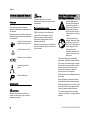
Caution where there is a risk of
damaging the machine or its individual
components.
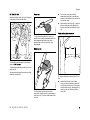
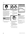
Pictograms
The meanings of the pictograms
attached to the machine are explained in
this manual.
Depending on the model concerned, the
following pictograms may be attached to
your machine.
Fuel tank; fuel mixture of
gasoline and engine oil
Chain oil tank; chain oil
Direction of chain rotation
Operate manual fuel
pump
Manual fuel pump
Symbols in text
WARNING
Warning where there is a risk of an
accident or personal injury or serious
damage to property.
2
NOTICE
Engineering improvements
STIHL's philosophy is to continually
improve all of its products. For this
reason we may modify the design,
engineering and appearance of our
products periodically.
Therefore, some changes, modifications
and improvements may not be covered
in this manual.
Safety Precautions and
Working Techniques
Special safety precautions must be observed
when working with the
pole pruner because it is
a high-speed, fast-cutting power tool with very
sharp cutters and a long
reach.
It is important that you
read the instruction manual before first use and
keep it in a safe place for
future reference. Nonobservance of the
instruction manual may
result in serious or even
fatal injury.
Observe all applicable local safety
regulations, standards and ordinances.
If you have not used this type of power
tool before: Have your dealer or other
experienced user show you how to
operate your machine or attend a
special course in its operation.
Minors should never be allowed to use a
power tool.
Keep bystanders, especially children,
and animals away from the work area.
When the power tool is not in use, shut it
off so that it does not endanger others.
Secure it against unauthorized use.
The user is responsible for avoiding
injury to third parties or damage to their
property.
HT 100, HT 101, HT 130, HT 131
English
The use of noise emitting power tools
may be restricted to certain times by
national or local regulations.
To operate the power tool you must be
rested, in good physical condition and
mental health.
If you have any condition that might be
aggravated by strenuous work, check
with your doctor before operating a
power tool.
Persons with pacemakers only: The
ignition system of your power tool
produces an electromagnetic field of a
very low intensity. This field may
interfere with some pacemakers. STIHL
recommends that persons with
pacemakers consult their physician and
the pacemaker manufacturer to reduce
any health risk.
Do not operate the power tool if you are
under the influence of any substance
(drugs, alcohol) which might impair
vision, dexterity or judgment.
Use your pole pruner for limbing only
(removing or pruning branches). Only
cut wood or wooden objects.
Do not use your power tool for any other
purpose because of the increased risk of
accidents.
Only use guide bars, chains, chain
sprockets and accessories that are
explicitly approved for this power tool
model by STIHL or are technically
identical. If you have any questions in
this respect, consult a servicing dealer.
HT 100, HT 101, HT 130, HT 131
Use only high quality tools and
accessories in order to avoid the risk of
accidents and damage to the machine.
STIHL recommends the use of genuine
STIHL tools, guide bars, chains, chain
sprockets and accessories. They are
specifically designed to match the
product and meet your performance
requirements.
Never attempt to modify your machine in
any way since this may increase the risk
of personal injury. STIHL excludes all
liability for personal injury and damage
to property caused while using
unauthorized attachments.
Do not use a pressure washer to clean
the unit. The solid jet of water may
damage parts of the unit.
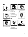
Clothing and Equipment
Wear proper protective clothing and
equipment.
Clothing must be sturdy
but allow complete freedom of movement. Wear
snug-fitting clothing, an
overall and jacket combination, do not wear a
work coat.
Avoid clothing that could get caught on
branches or brush or moving parts of the
machine. Do not wear a scarf, necktie or
jewelry. Tie up and confine long hair
(e.g. with a hair net, cap, hard hat, etc.).
Wear steel-toed safety
boots with non-slip soles
and cut-retardant inserts.
WARNING
To reduce the risk of eye
injuries, wear snug-fitting
safety glasses in accordance with European
Standard EN 166. Make
sure the safety glasses
are a good fit.
Wear hearing protection, e.g. earplugs
or ear muffs.
Wear a safety hard hat with chin strap
where there is a danger of head injuries
from falling objects.
Wear heavy-duty work
gloves made of durable
material (e.g. leather).
STIHL offers a comprehensive range of
personal protective clothing and
equipment.
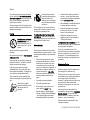
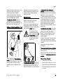
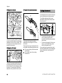
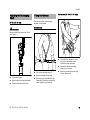
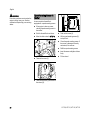
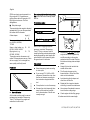
Transporting the Power Tool
390BA000 KN
Do not lend or rent your power tool
without the instruction manual. Be sure
that anyone using it understands the
information contained in this manual.
Always turn off the engine.
Always fit the chain guard (scabbard) –
even when you carry the unit for short
distances.
3
English
Carry the power tool properly balanced
by the drive tube. To reduce the risk of
serious burn injuries, avoid touching hot
parts of the machine, especially the
surface of the muffler.
Transporting by vehicle: Properly secure
your power tool to prevent turnover, fuel
spillage and damage.
Fueling
Gasoline is an extremely
flammable fuel. Keep
clear of naked flames. Do
not spill any fuel – do not
smoke.
Always shut off the engine before
refueling.
Do not fuel a hot engine – fuel may spill
and cause a fire.
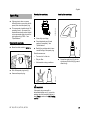
Open the fuel cap carefully to allow any
pressure build-up in the tank to release
slowly and avoid fuel spillage.
Insert the fuel cap with
hinged grip (bayonet-type
cap) correctly in the
opening, turn it clockwise
as far as stop and fold the
grip down.
This reduces the risk of unit vibrations
causing the fuel cap to loosen or come
off and spill quantities of fuel.
To reduce the risk of serious or fatal
burn injuries, check for fuel leakage. If
fuel leakage is found, do not start or run
the engine until leak is fixed.
Before Starting
Check that your power tool is properly
assembled and in good condition – refer
to appropriate chapters in the instruction
manual.
–
Fuel your power tool only in wellventilated areas. If you spill fuel, wipe
the machine immediately – if fuel gets on
your clothing, change immediately.
Your power tool comes standard with
either a screw-type or bayonet-type fuel
cap.
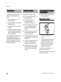
After fueling, tighten
down the screw-type fuel
cap as securely as
possible.
Check the fuel system for leaks,
paying special attention to visible
parts such as the tank cap, hose
connections and the manual fuel
pump (on machines so equipped). If
there are any leaks or damage, do
not start the engine – risk of fire.
Have your machine repaired by a
servicing dealer before using it
again.
–
Correctly mounted guide bar
–
Correctly tensioned chain
–
Slide control / stop switch must
move easily to STOP or 0.
–
Smooth action of throttle trigger
lockout (if fitted) and throttle trigger
– the throttle trigger must return
automatically to the idle position.
–
Check that the spark plug boot is
secure – a loose boot may cause
arcing that could ignite combustible
fumes and cause a fire.
–
Never attempt to modify the controls
or safety devices in any way.
–
Keep the handles dry and clean –
free from oil and dirt – for safe
control of the power tool.
–
Adjust the harness to suit your
height and reach. See chapter on
"Fitting the Harness".
To reduce the risk of accidents, do not
operate your power tool if it is damaged
or not properly assembled.
If you use a shoulder strap or full
harness: Practice removing and putting
down the machine as you would in an
emergency. To avoid damage, do not
throw the machine to the ground when
practicing.
Starting the Engine
Start the engine at least 3 meters from
the fueling spot, outdoors only.
Place the unit on firm ground in an open
area. Make sure you have good balance
and secure footing. Hold the unit
securely. The chain must be clear of the
ground and all other obstructions
because it may begin to run when the
engine starts.
Your power tool is designed to be
operated by one person only. To reduce
the risk of injury, do not allow other
persons within 15 meters of your own
position – even when starting.
Start the engine as described in the
instruction manual.
4
HT 100, HT 101, HT 130, HT 131
English
Note that the chain continues to run for a
short period after you let go of the
throttle trigger (flywheel effect).
Check idle speed setting: The chain
must not move when the engine is idling
with the throttle trigger released.
To reduce the risk of fire, keep hot
exhaust gases and hot muffler away
from easily combustible materials (e.g.
wood chips, bark, dry grass, fuel).
Holding and Controlling the Power Tool
Machines with telescoping shaft: Only
extend the telescoping shaft as far as
necessary for the cutting work that
needs to be done.
During Operation
Make sure you always have good
balance and secure footing.
In the event of impending danger or in
an emergency, switch off the engine
immediately by moving the slide control
/ stop switch to STOP or 0.
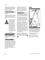
This power tool is not
insulated against electric
shock. To reduce the risk
of electrocution maintain
a minimum clearance of
15 meters from electric
power lines.
m
390BA026 KN
t)
0f
(5
HT 100, HT 101, HT 130, HT 131
Maintain a minimum clearance of
15 meters between the bar nose and
electric power lines. Electricity can jump
considerable distances by means of
arcing. Higher voltage increases the
distance electricity can arc. Have the
power switched off before starting
cutting work in the immediate vicinity of
power lines.
To reduce the risk of injury, shut off the
engine before changing the saw chain.
Make sure the idle speed setting is
correct. The chain must not run when
the engine is idling with the throttle
trigger released.
It the chain still rotates, have your dealer
make proper adjustments or repairs.
Check and correct the idle speed setting
regularly.
Never leave a running power tool
unattended.
15
Always hold the unit firmly with both
hands – right hand on the control handle,
left hand on the drive tube – even if you
are left-handed. Wrap your fingers
around the control handle and drive
tube.
To reduce the risk of damage to
property, also maintain this distance
from other objects (vehicles, windows).
15m (50ft)
Take special care in slippery conditions
(ice, wet ground, snow) – on slopes or
uneven ground.
Watch out for obstacles: Roots and tree
stumps which could cause you to trip or
stumble.
When working at heights:
To reduce the risk of injury from falling
objects and thrown pieces of wood, do
not allow any other persons within a
radius of 15 meters of your own position.
–
Always use a lift bucket
–
Never work on a ladder or in a tree
–
Never work on an insecure support
–
Never operate your power tool with
one hand
5
English
To reduce the risk of accidents, take a
break in good time to avoid tiredness or
exhaustion.
Work calmly and carefully – in daylight
conditions and only when visibility is
good. Stay alert so as not to endanger
others.
Your power tool produces
toxic exhaust fumes as
soon as the engine is
running. These fumes
may be colorless and
odorless and contain
unburned hydrocarbons
and benzol. Never run
the engine indoors or in
poorly ventilated locations, even if your model
is equipped with a catalytic converter.
To reduce the risk of serious or fatal
injury from breathing toxic fumes,
ensure proper ventilation when working
in trenches, hollows or other confined
locations.
Operate your power tool so that it
produces a minimum of noise and
emissions – do not run the engine
unnecessarily, accelerate the engine
only when working.
Limbing
To reduce the risk of fire, do not smoke
while operating or standing near your
power tool. Note that combustible fuel
vapor may escape from the fuel system.
The dusts (e.g. sawdust), vapor and
smoke produced during operation may
be dangerous to health. If dust levels are
very high, wear a suitable respirator.
If your power tool is subjected to
unusually high loads for which it was not
designed (e.g. heavy impact or a fall),
always check that it is in good condition
before continuing work – see also
"Before Starting". Check the fuel system
in particular for leaks and make sure the
safety devices are working properly. Do
not continue operating your power tool if
it is damaged. In case of doubt, consult
your servicing dealer.
If you use a shoulder strap, make sure
exhaust gases are diverted away from
your body since there is otherwise a risk
of fire.
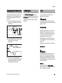
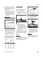
max 60°
390BA025 KN
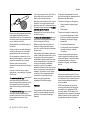
Be particularly alert and cautious when
wearing hearing protection because
your ability to hear warnings (shouts,
alarms, etc.) is restricted.
Hold the pole pruner at an angle. Do not
stand directly underneath the limb being
cut. Do not exceed an angle of 60° from
the horizontal. Watch for falling wood.
Keep the work area clear – remove
interfering limbs and brush.
Before limbing, establish a path of
escape and remove all obstacles.
To reduce the risk of accidents, stop
work immediately in the event of
nausea, headache, visual disturbances
(e.g. reduced field of vision), problems
with hearing, dizziness, deterioration in
ability to concentrate. Apart from other
possibilities, these symptoms may be
caused by an excessively high
concentration of exhaust gases in the
work area.
6
HT 100, HT 101, HT 130, HT 131
390BA052 KN
English
Position the cutting attachment with the
hook against the branch and then
perform the cross-cut. This reduces the
risk of the pruner being jerked forward
as you start the cross-cut.
Always start the cut with the engine at
full throttle.
Always cut with a correctly sharpened,
properly tensioned chain – the depth
gauge setting must not be too large.
Do not operate your power tool in the
starting throttle position – engine speed
cannot be controlled in this position.
Perform cross-cut from the top
downward to avoid the chain pinching in
the cut.
If branch is thick or heavy, make a
relieving cut – see chapter on "Using the
Pole Pruner".
To reduce the risk of injury, take special
care when cutting branches under
tension. Always make a relieving cut on
the compression side first and then
perform the bucking cut at the tension
side.
To reduce the risk of injury, take special
care when cutting shattered wood
because of the risk of injury from slivers
being caught and thrown in your
direction.
HT 100, HT 101, HT 130, HT 131
If on a slope, stand on the uphill side or
to one side of the branch to be cut.
Watch out for rolling branches.
No general recommendation can be
given for the length of usage because it
depends on several factors.
Note when reaching the end of a cut that
the unit is no longer supported by the
guide bar in the cut. You have to take the
full weight of the machine since it might
otherwise go out of control.
The period of usage is prolonged by:
Always pull the unit out of the cut with
the chain running.
The period of usage is shortened by:
–
Hand protection (wearing warm
gloves)
–
Work breaks
–
Any personal tendency to suffer
from poor circulation (symptoms:
frequently cold fingers, tingling
sensations).
Make sure your saw chain does not
touch any foreign materials: Stones,
nails, etc. may be flung off and damage
the saw chain.
–
Low outside temperatures.
–
If the rotating chain makes contact with
a rock or other solid object there is a risk
of sparking which may cause easily
combustible material to catch fire under
certain circumstances. Dry plants and
scrub are also easily combustible,
especially in hot and dry weather
conditions. If there is a risk of fire, do not
use your pole pruner near combustible
materials, dry plants or scrub. Always
contact your local forest authority for
information on a possible fire risk.
The force with which the handles
are held (a tight grip restricts
circulation).
Continual and regular users should
monitor closely the condition of their
hands and fingers. If any of the above
symptoms appear (e.g. tingling
sensation in fingers), seek medical
advice.
To reduce the risk of accidents, use your
pole pruner for limbing and pruning only.
It is not designed for felling.
Before leaving the power tool
unattended: Shut off the engine.
Vibrations
Prolonged use of the power tool may
result in vibration-induced circulation
problems in the hands (whitefinger
disease).
Maintenance and Repairs
Service the machine regularly. Do not
attempt any maintenance or repair work
not described in the instruction manual.
Have all other work performed by a
servicing dealer.
STIHL recommends that you have
servicing and repair work carried out
exclusively by an authorized STIHL
servicing dealer. STIHL dealers are
regularly given the opportunity to attend
training courses and are supplied with
the necessary technical information.
7
English
Only use high-quality replacement parts
in order to avoid the risk of accidents
and damage to the machine. If you have
any questions in this respect, consult a
servicing dealer.
STIHL recommends the use of genuine
STIHL replacement parts. They are
specifically designed to match your
model and meet your performance
requirements.
To reduce the risk of injury, always shut
off the enginebefore carrying out any
maintenance or repairs or cleaning the
machine. – Exception: Carburetor and
idle speed adjustments.
Do not turn the engine over on the
starter with the spark plug boot or spark
plug removed unless the slide control /
stop switch is on STOP or 0 since there
is otherwise a risk of fire from
uncontained sparking.
To reduce the risk of fire, do not service
or store your machine near open flames.
Check the fuel filler cap for leaks at
regular intervals.
Use only a spark plug of the type
approved by STIHL and make sure it is
in good condition – see "Specifications".
Inspect the ignition lead (insulation in
good condition, secure connection).
Check the condition of the muffler.
To reduce the risk of fire and damage to
hearing, do not operate your machine if
the muffler is damaged or missing.
Do not touch a hot muffler since burn
injury will result.
8
Stopping the engine
–
before checking chain tension.
–
before retensioning the chain.
–
before replacing the chain.
–
before rectifying problems.
Using the Unit
Preparations
N
Wear suitable protective clothing,
observe safety precautions.
N
Adjust telescoping shaft to the
required length (HT 101, HT 131
only).
N
Start the engine.
Always change the chain, guide bar and
sprocket in good time.
N
Put on the shoulder strap.
Store fuel and chain lubricant in properly
labelled, safety-type canisters only.
When handling gasoline, avoid direct
contact with the skin and avoid inhaling
fuel vapour – health risk.
Cutting Sequence
Observe sharpening instructions – keep
the chain and guide bar in good
condition at all times for safe and correct
handling of the saw. The chain must be
properly sharpened, tensioned and well
lubricated.
To allow branches a free fall, always cut
the lower branches first. Prune heavy
branches (large diameter) in several
controllable pieces.
WARNING
Never stand directly underneath the
branch you are cutting – be wary of
falling branches. Note that a branch may
spring back at you after it hits the ground
– risk of injury.
Disposal
Do not throw cuttings into the garbage
can – they can be composted.
Working Techniques
Hold the control handle with your right
hand, and the shaft with your left hand.
Your left arm should be extended to the
most comfortable position.
HT 100, HT 101, HT 130, HT 131
English
Cross-cut
HT 100, HT 130
N
To do this, apply the cutting
attachment and pull it across the
bottom of the branch in an arc as far
as the bar nose.
N
Perform the cross-cut (2) – position
the bar with the hook against the
branch and then perform the crosscut.
390BA052 KN
Always hold the shaft with your left hand
in the area of the handle hose.
Flush-cutting thick branches
To avoid pinching the bar in the cut,
position the cutting attachment with the
hook against the branch and then
perform the cross-cut from the top
downwards.
A
390BA018 KN
Relieving cut
The shaft should always be held at an
angle of 60° or less.
4
2
390BA024 KN
The least tiring working position is a tool
angle of 60°.
Any lesser angle may be used to suit the
situation concerned.
1
If branch diameter is more than 10 cm,
first
390BA041 KN
N
To avoid tearing the bark on thick
branches, always start by performing a
relieving cut (1) on the underside of the
branch.
HT 100, HT 101, HT 130, HT 131
3
perform undercut (3) and then
cross-cut at a distance of about 20
cm (A) from the final cut. Then carry
out the flush-cut (4), starting with a
relieving cut and finishing with a
cross-cut.
9
English
Cutting above obstacles
30° angle drive (special accessory)
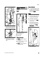
Cutting Attachment
A cutting attachment consists of the saw
chain, guide bar and chain sprocket.
1
The cutting attachment that comes
standard is designed to exactly match
the pole pruner.
1
The unit's long reach makes it possible
to prune branches that are overhanging
obstacles, such as rivers or lakes. The
tool angle in this case depends on the
position of the branch.
Cutting from a lift bucket
390BA053 KN
390BA020 KN
a
The angle drive keeps the cutting
attachment at an angle of 30° to the
drive tube.
The angle drive may be adjusted on the
drive tube to the following positions only:
1
–
The pitch (t) of the saw chain (1),
chain sprocket and the nose
sprocket of the Rollomatic guide bar
must match.
–
The drive link gauge (2) of the saw
chain (1) must match the groove
width of the guide bar (3).
If non-matching components are used,
the cutting attachment may be damaged
beyond repair after a short period of
operation.
390BA058 KN
2
For cross-cutting vertical branches
and bushes.
For a better view of the cutting
attachment.
3
001BA248 KN
2
2
The unit's long reach enables cutting to
be performed next to the trunk without
the risk of the lift bucket damaging other
branches. The tool angle in this case
depends on the position of the branch.
10
HT 100, HT 101, HT 130, HT 131
English
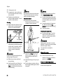
Chain Scabbard
Mounting the Bar and Chain
Fitting the chain
001BA244 KN
Removing the chain sprocket cover
The length of the matching guide bars is
marked on the side of the chain
scabbard.
Unscrew the nut and remove the
cover.
1
2
N
HT 100, HT 101, HT 130, HT 131
390BA003 KN
N
WARNING
390BA043 KN
If guide bars of different lengths are
mounted to the pole pruner, always use
a chain scabbard of the correct length
which covers the complete guide bar.
390BA042 KN
The scope of supply includes a bar
scabbard that matches the cutting
attachment.
Turn the screw (1)
counterclockwise until the tensioner
slide (2) butts against the left end of
the housing slot, then back it off 5
full turns.
Wear work gloves to protect your hands
from the sharp cutters.
N
Fit the chain – start at the bar nose.
11
English
Tensioning the Chain
5
Checking Chain Tension
N
Fit the guide bar over the screw (3)
and engage peg of tensioner slide in
the hole (4) – place the chain over
the sprocket (5) at the same time.
N
Turn the tensioning screw (1)
clockwise until there is very little
chain sag on the underside of the
bar – and the drive link tangs are
engaged in the bar groove.
N
Refit the cover and screw on the nut
fingertight.
N
Go to chapter on "Tensioning the
Saw Chain"
1
Retensioning during cutting work:
N
Stopping the engine
N
Loosen the nut.
N
Hold the bar nose up.
N
Use a screwdriver to turn the
tensioning screw (1) clockwise until
the chain fits snugly against the
underside of the bar.
N
While still holding the bar nose up,
tighten down the nut firmly.
N
Go to "Checking Chain Tension".
A new chain has to be retensioned more
often than one that has been in use for
some time.
N
12
390BA046 KN
3
390BA045 KN
4
390BA044 KN
1
N
Shut off the engine
N
Wear work gloves to protect your
hands.
N
The chain must fit snugly against
the underside of the bar and it must
still be possible to pull the chain
along the bar by hand.
N
If necessary, retension the chain.
A new chain has to be retensioned more
often than one that has been in use for
some time.
N
Check chain tension frequently –
see chapter on "Operating
Instructions".
Check chain tension frequently –
see chapter on "Operating
Instructions".
HT 100, HT 101, HT 130, HT 131
English
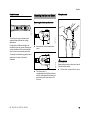
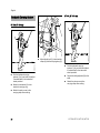
Adjusting the Throttle Cable
4-MIX Engine
A properly adjusted throttle cable is the
precondition for correct operation in the
full throttle, starting throttle and idle
positions.
N
Adjust the throttle cable only when
the unit is completely and properly
assembled.
The STIHL 4-MIX engine features
mixture lubrication and must be run on a
fuel mixture of gasoline and engine oil.
It operates otherwise on the 4-stroke
principle.
Fuel
Your engine requires a mixture of
gasoline and engine oil.
WARNING
For health reasons, avoid direct skin
contact with gasoline and avoid inhaling
gasoline vapor.
002BA163 KN
STIHL MotoMix
N
Use a suitable tool to push the slide
to the end of the slot (see
illustration).
1
N
STIHL MotoMix uses STIHL HP Ultra
two-stroke engine oil for an extra long
engine life.
MotoMix is not available in all markets.
Mixing Fuel
002BA161 KN
2
STIHL recommends the use of STIHL
MotoMix. This ready-to-use fuel mix
contains no benzol or lead, has a high
octane rating and ensures that you
always use the right mix ratio.
Press down the throttle trigger
lockout (1) and squeeze the throttle
trigger (2) (full throttle) – this sets
the throttle cable correctly.
NOTICE
Unsuitable fuels or lubricants or mix
ratios other than those specified may
result in serious damage to the engine.
Poor quality gasoline or engine oil may
damage the engine, sealing rings, hoses
and the fuel tank.
Gasoline
Use only high-quality brand-name
gasoline with a minimum octane rating
of 90 – leaded or unleaded.
HT 100, HT 101, HT 130, HT 131
13
English
If your machine is equipped with a
catalytic converter, you must use
unleaded gasoline.
NOTICE
A few tankfuls of leaded gasoline will
greatly reduce the efficiency of the
catalytic converter.
Gasoline with an ethanol content of
more than 10% can cause running
problems in engines with a manually
adjustable carburetor and should not be
used in such engines.
Engines equipped with M-Tronic deliver
full power when run on gasoline with an
ethanol content of up to 25% (E25).
Engine oil
Use only high-quality two-stroke engine
oil – preferably STIHL HP, HP Super or
HP Ultra, which are specially formulated
for use in STIHL engines. HP Ultra
guarantees high performance and a
long engine life.
These engine oils are not available in all
markets.
Use only STIHL 50:1 two-stroke engine
oil for the fuel mix in models with a
catalytic converter.
Examples
Gasoline
Liters
1
5
10
15
20
25
N
STIHL engine oil 50:1
Liters
(ml)
0.02
(20)
0.10
(100)
0.20
(200)
0.30
(300)
0.40
(400)
0.50
(500)
Dispose of remaining fuel and cleaning
fluid properly in accordance with local
regulations and environmental
requirements.
Use a canister approved for storing
fuel. Pour oil into canister first, then
add gasoline and mix thoroughly.
Storing Fuel
Store fuel only in approved safety-type
fuel canisters in a dry, cool and safe
location protected from light and the sun.
Fuel mix ages – only mix sufficient fuel
for a few weeks work. Do not store fuel
mix for longer than 30 days. Exposure to
light, the sun, low or high temperatures
can quickly make the fuel mix unusable.
STIHL MotoMix may be stored for up to
2 years without any problems.
N
Thoroughly shake the mixture in the
canister before fueling your
machine.
Mix Ratio
STIHL 50:1 two-stroke engine oil: 50
parts gasoline to 1 part oil
WARNING
Pressure may build up in the canister –
open it carefully.
N
14
Clean the fuel tank and canister
from time to time.
HT 100, HT 101, HT 130, HT 131
English
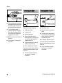
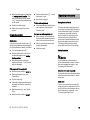
Refueling
002BA419 KN
Fueling
Preparations
Take care not to spill fuel while fueling
and do not overfill the tank. STIHL
recommends use of the STIHL filling
system (special accessory).
Closing the cliplock filler cap
Threaded filler cap
249BA053 KN
002BA420 KN
249BA055 KN
Opening the cliplock filler cap
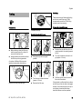
N
Before fueling, clean the filler cap
and the area around it so that dirt
cannot fall into the tank.
N
Always position the machine so that
the filler cap is facing upwards.
N
Swing the clip into an upright
position
N
Turn the cap counterclockwise
(approx. 1/4 turn)
N
Remove the filler cap
N
Position the cap with the clip in an
upright position; the markings must
line up
N
Turn cap clockwise as far as it will
go (approx. 1/4 turn)
N
Fold the cliplock down so that it is
flush with the surface
Cliplock filler cap (bayonet-type)
HT 100, HT 101, HT 130, HT 131
249BA056 KN
249BA054 KN
002BA418 KN
A number of different filler caps are
installed as standard at the factory.
If the cliplock is not flush with the surface
and the lug on the clip does not engage
entirely in the recess (arrow), the cap is
not properly closed and the steps
described above must be repeated.
15
English
002BA447 KN
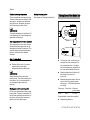
Chain Lubricant
N
Turn the cap counterclockwise until
it can be removed from the tank
opening.
N
Remove the cap.
Filling up with fuel
Take care not to spill fuel while fueling
and do not overfill the tank. STIHL
recommends you use the STIHL filler
nozzle (special accessory).
Closing screw-type tank cap
For automatic and reliable lubrication of
the chain and guide bar – use only an
environmentally compatible quality
chain and bar lubricant. Rapidly
biodegradable STIHL BioPlus is
recommended.
NOTICE
Biological chain oil must be resistant to
aging (e.g. STIHL BioPlus), since it will
otherwise quickly turn to resin. This
results in hard deposits that are difficult
to remove, especially in the area of the
chain drive and chain. It may even cause
the oil pump to seize.
002BA448 KN
Do not use waste oil. Renewed contact
with waste oil can cause skin cancer.
Moreover, waste oil is environmentally
harmful.
Place the cap in the opening.
N
Turn the cap clockwise as far as
stop and tighten it down as firmly as
possible by hand.
16
NOTICE
A full chain oil tank is sufficient for only
half a tankful of fuel. Check the oil level
regularly during cutting work. Never
allow the oil tank to run dry.
Preparations
The service life of the chain and guide
bar depends on the quality of the
lubricant. It is therefore essential to use
only a specially formulated chain
lubricant.
WARNING
N
Filling Chain Oil Tank
390BA047 KN
Opening screw-type tank cap
N
Thoroughly clean the oil filler cap
and the area around it to ensure that
no dirt falls into the tank.
N
Position the machine so that the
tank cap faces up.
NOTICE
Waste oil does not have the necessary
lubricating properties and is unsuitable
for chain lubrication.
HT 100, HT 101, HT 130, HT 131
English
N
002BA579 KN
002BA578 KN
002BA575 KN
Opening
N
Remove the cap.
N
Filling the chain oil tank
Raise the grip until it is upright.
N
While holding the cap depressed,
turn it clockwise until it engages in
position.
Fill up with chain oil
Closing
Marks on tank cap and oil tank must line
up.
HT 100, HT 101, HT 130, HT 131
002BA580 KN
The marks on the cap and oil tank are
then in alignment.
002BA577 KN
Turn the cap counterclockwise
(about a quarter turn).
002BA577 KN
N
STIHL recommends you use the STIHL
filler nozzle for chain oil (special
accessory).
Grip must be vertical:
N
Fit the cap – marks on tank cap and
oil tank must line up.
N
Press the cap down as far as stop.
002BA581 KN
002BA576 KN
Take care not to spill chain oil while
refilling and do not overfill the tank.
N
Fold the grip down.
17
English
Tank cap is locked.
If the oil level in the tank does not go
down, the reason may be a problem in
the oil supply system: Check chain
lubrication, clean the oilways, contact
your dealer for assistance if necessary.
STIHL recommends that you have
servicing and repair work carried out
exclusively by an authorized STIHL
servicing dealer.
Left:
Right:
Bottom of cap is twisted –
inner mark (1) in line with
outer mark.
Bottom of cap in correct position – inner mark is under the
grip. It is not in line with the
outer mark.
002BA576 KN
If the tank cap cannot be locked in the oil
tank opening
Bottom of cap is twisted in relation to
top.
N
18
Remove the cap from the oil tank
and check it from above.
N
Place the cap on the opening and
rotate it counterclockwise until it
engages the filler neck.
N
Continue rotating the cap
counterclockwise (about a quarter
turn) – this causes the bottom of the
cap to be turned to the correct
position.
N
Turn the cap clockwise and lock it in
position – see section on "Closing".
390BA048 KN
002BA583 KN
1
002BA584 KN
Checking Chain Lubrication
The saw chain must always throw off a
small amount of oil.
NOTICE
Never operate your saw without chain
lubrication. If the chain runs dry, the
whole cutting attachment will be
irretrievably damaged within a very short
time. Always check chain lubrication and
the oil level in the tank before starting
work.
Every new chain has to be broken in for
about 2 to 3 minutes.
After breaking in the chain, check chain
tension and adjust if necessary – see
"Checking Chain Tension".
HT 100, HT 101, HT 130, HT 131
English
Adjusting the Telescoping
Shaft
Full harness (HT 100, HT 101 only)
Fitting the Harness
The type and style of the harness
depend on the market.
HT 101, HT 131 only
Shoulder strap
Always shut off the engine and fit the
chain guard
1
1
3
N
Loosen the screw.
N
Adjust shaft to the required length.
N
Tighten down the screw firmly.
HT 100, HT 101, HT 130, HT 131
390BA040 KN
390BA049 KN
2
N
Put on the shoulder strap (1).
N
Adjust the length of the strap.
N
With the power tool attached, the
carabiner (2) must be at about the
same height as your right hip.
2
N
Put on the full harness (1) and
sling (2) as described in the
instruction sheet provided.
N
Adjust the harness and thigh
strap (3) as required.
N
Rest the powerhead in the sling
during cutting work.
386BA012 KN
WARNING
19
English
HT 101, HT 131 only
Backpack Carrying System
HT 100, HT 130 only
4
1
5
2
1
2
246BA013 KN
N
N
Put the backpack carrying
system (1) on your back and adjust
it as described in the instruction
sheet provided.
N
Attach the carabiner (2) to the
machine's carrying ring.
N
Attach the pole pruner to the
carrying strap when cutting.
20
246BA010 KN
246BA014 KN
3
Adjust the hip belt (3), both shoulder
straps (4) and the carrying strap (5).
N
Put the backpack carrying
system (1) on your back and adjust
it as described in the instruction
sheet provided.
N
Secure the sliding adjuster (2) to the
shaft.
N
Attach the pole pruner to the
carrying strap when cutting.
HT 100, HT 101, HT 130, HT 131
English
Symbol on slide control
Starting / Stopping the
Engine
4
7
Controls
Starting
4
STOP-
7
5
N
Press down the trigger lockout lever
and squeeze the throttle trigger
N
and hold them in that position.
N
Move the slide control to START
and hold it there.
N
Now release the throttle trigger,
slide control and trigger lockout in
that order. This is the starting
throttle position.
STOP
2
Adjust the hip belt (3), both shoulder
straps (4) and the carrying strap (5).
1
N
Squeeze the grips to move the
sliding adjuster up or down the
shaft.
1
2
3
Throttle trigger lockout
Throttle trigger
Slide control
9
8
Positions of slide control
4
5
6
STOP-0 – engine off – ignition is
switched off
F – normal run position – the engine
is running or can start
START – ignition is switched on –
the engine can start
249BA007 KN
246BA012 KN
002BA181 KN
N
6
246BA011 KN
3
5
START
3
h – stop symbol and arrow. To stop
the engine, push the slide control in
the direction of the arrow on the stop
symbol (h) to STOP-0.
N
HT 100, HT 101, HT 130, HT 131
Set the choke knob (8):
21
English
g if the engine is cold
e for warm start – also use this position if the engine has been running
but is still cold.
N
Press the manual fuel pump
bulb (9) at least five times – even if
the bulb is filled with fuel.
NOTICE
Do not stand or kneel on the drive tube.
This will bend the drive tube and may
result in permanent damage.
Alternative method:
N
Cranking
N
Remove the chain scabbard. Check
that the chain is not touching the
ground or any other obstacles.
Remove the chain scabbard.
Position the drive tube on a branch
so that it is held by the hook.
NOTICE
Do not pull out the starter rope all the
way – it might otherwise break.
N
Do not let the starter grip snap back.
Guide it slowly back into the housing
so that the starter rope can rewind
properly.
N
Crank the engine until it begins to
fire. After no more than five
attempts, turn the choke knob to e.
N
Continue cranking.
As soon as the engine runs
390BA033 LA
N
N
WARNING
Make sure the carburetor is correctly
adjusted. The saw chain must not rotate
when the engine is idling.
Place the unit on the ground: It must
rest securely on the engine support
and the hook. If necessary, rest the
hook on a raised support (e.g. a
branch, mound or something
similar).
WARNING
Your machine is now ready for
operation.
N
Check that nobody is standing within the
working range of the pruner.
N
Make sure you have a safe and
secure footing.
N
Hold the unit with your left hand on
the fan housing and press it down
firmly – your thumb should be under
the fan housing.
22
Blip the throttle trigger. The slide
control moves to the normal run
position F – and the engine settles
down to idle speed.
Hold the unit firmly with your left
hand on the fan housing – your
thumb should be under the fan
housing.
N
Hold the starter grip with your right
hand.
N
Pull the starter grip slowly until you
feel it engage and then give it a brisk
strong pull.
Stopping the engine
N
Push the slide control in the
direction of the arrow on the stop
symbol (h) to STOP-0.
At very low outside temperatures
As soon as the engine runs:
HT 100, HT 101, HT 130, HT 131
English
N
Blip the throttle trigger to disengage
the starting throttle position. The
slide control moves to the normal
run F – and the engine settles down
to idle speed.
N
Open the throttle slightly.
N
Warm up the engine for a short
period.
If engine does not start
N
Set the choke knob to e – even if
the engine is cold.
N
Now start the engine.
Throttle cable adjustment
N
Fuel tank run until completely dry
N
After refueling, press the manual
fuel pump bulb at least five times –
even if the bulb is filled with fuel.
N
Set the choke knob according to
engine temperature.
N
Start the engine.
Choke knob
If you did not turn the choke knob to e
quickly enough after the engine began to
fire, the combustion chamber is flooded.
N
Turn the choke knob to e.
N
Set the slide control, lockout lever
and throttle trigger to the starting
throttle position.
N
Start the engine by pulling the
starter rope briskly – 10 to 20 pulls
may be necessary.
If the engine still does not start
N
Move the slide control to STOP-0.
N
Remove the spark plug – see
"Spark Plug".
N
Dry the spark plug.
N
Crank the engine several times with
the starter to clear the combustion
chamber.
N
Refit the spark plug – see "Spark
Plug".
N
Move the slide control to START.
HT 100, HT 101, HT 130, HT 131
Check adjustment of throttle cable –
see chapter on "Adjusting the
Throttle Cable".
Operating Instructions
During Break-In Period
A factory-new machine should not be
run at high revs (full throttle off load) for
the first three tank fillings. This avoids
unnecessary high loads during the
break-in period. As all moving parts
have to bed in during the break-in
period, the frictional resistances in the
engine are greater during this period.
The engine develops its maximum
power after about 5 to 15 tank fillings.
During Operation
NOTICE
Do not make the mixture leaner to
achieve an apparent increase in power –
this could damage the engine – see
"Adjusting the Carburetor".
Check chain tension frequently
A new chain has to be retensioned more
often than one that has been in use for
some time.
Chain cold
Tension is correct when the chain fits
snugly against the underside of the bar
and can still be pulled along the bar by
hand. Retension if necessary – see
"Tensioning the Saw Chain".
23
English
Chain at operating temperature
Storing for a long period
The chain stretches and begins to sag.
The drive links must not come out of the
bar groove – the chain may otherwise
jump off the bar. Retension the chain –
see "Tensioning the Saw Chain".
See chapter on "Storing the Machine"
Taking Care of the Guide Bar
2
NOTICE
The chain contracts as it cools down. If it
is not slackened off, it can damage the
gear shaft and bearings.
Allow engine to run for a short while at
idle speed so that engine heat can be
dissipated by the flow of cooling air. This
protects engine-mounted components
(ignition, carburetor) from thermal
overload.
1
After Finishing Work
N
Always slacken off the chain after
finishing work. The chain contracts as it
cools down. If it is not slackened off, it
can damage the gear shaft and
bearings.
Storing your saw for a short period
Fit the chain scabbard and allow engine
to cool down. To avoid condensation, fill
the fuel tank and keep the machine in a
dry place, well away from sources of
ignition, until you need it again.
24
N
Turn the bar over – every time you
sharpen the chain and every time
you replace the chain – this helps
avoid one-sided wear, especially at
the nose and underside of the bar.
N
Regularly clean the oil inlet hole (1),
the oilway (2) and the bar
groove (3).
N
Measure the groove depth – with the
scale on the filing gauge (special
accessory) – in the area used most
for cutting.
Slacken off the chain if you have
retensioned it at operating
temperature during cutting work.
NOTICE
3
390BA050 KN
After long period of full-throttle operation
Chain type Chain pitch
Picco
3/8" P
Minimum
groove depth
5.0 mm
If groove depth is less than specified:
N
Replace the guide bar.
HT 100, HT 101, HT 130, HT 131
English
Cleaning the Air Filter
Adjusting the Carburetor
The carburetor comes from the factory
with a standard setting.
If there is a noticeable loss of engine
power
This setting provides an optimum fuel-air
mixture under most operating
conditions.
4
With this carburetor it is only possible to
adjust the high speed screw within fine
limits.
2
273BA006 KN
1
N
Turn the choke knob to g
N
Take out the screw (1) and remove
the filter cover (2).
N
Clean away loose dirt from around
the filter.
N
Grip the filter element (3) at the
cutout (arrow) in the filter
housing (4) and remove it.
N
N
Fit a new filter element. As a
temporary measure you can knock it
out on the palm of your hand or blow
it out with compressed air. Do not
wash.
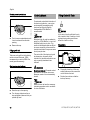
Adjusting idle speed
Engine stops while idling
H L
LA
N
Warm up the engine for about
3 minutes.
N
Turn the idle speed screw (LA)
slowly clockwise until the engine
runs smoothly – the chain must not
rotate.
Replace damaged parts.
Installing the filter
Chain rotates when engine is idling
N
HT 100, HT 101, HT 130, HT 131
N
Install the filter element in the filter
housing and fit the cover.
N
Insert the screw and tighten it down
firmly.
249BA066 KN
The drive link tangs will otherwise
scrape along the bottom of the groove –
the cutters and tie straps will not ride on
the bar rails.
Turn the idle speed screw (LA)
counterclockwise until the chain
stops running and then turn the
screw about another 1/2 to 3/4 turn
in the same direction.
25
English
WARNING
If the chain continues moving when the
engine is idling, have your machine
checked and repaired by your servicing
dealer.
Spark Arresting Screen in
Muffler
In some countries the muffler is
equipped with a spark arresting screen.
N
If the engine is down on power,
check the spark arresting screen in
the muffler.
N
Wait for the muffler to cool down.
N
Take out the screw (4).
N
Move the slide control to STOP-0.
N
Lift the spark arresting screen (5)
and pull it out.
N
Clean the spark arresting screen. If
the screen is damaged or heavily
carbonized, fit a new one.
N
Refit the spark arresting screen.
N
Insert the screw and tighten it down
firmly.
N
Fit the shroud.
249BA059 KN
1
Take out the screw (1).
3
2
N
26
2
249BA060 KN
N
Take out the screws (2) and remove
the shroud (3).
HT 100, HT 101, HT 130, HT 131
English
If the engine is down on power,
difficult to start or runs poorly at idle
speed, first check the spark plug.
N
Fit a new spark plug after about 100
operating hours – or sooner if the
electrodes are badly eroded. Install
only suppressed spark plugs of the
type approved by STIHL – see
"Specifications".
Removing the spark plug
N
Move the slide control to STOP-0.
A
N
Clean dirty spark plug.
N
Check electrode gap (A) and
readjust if necessary – see
"Specifications".
N
Rectify the problems which have
caused fouling of the spark plug.
2
3
002BA178 KN
N
Installing the spark plug
000BA039 KN
Checking the spark plug
Spark Plug
Possible causes are:
249BA063 KN
1
Pull off the spark plug boot (1).
N
Unscrew the spark plug.
Too much oil in fuel mix.
–
Dirty air filter.
–
Unfavorable running conditions.
N
Screw the spark plug (3) into the
cylinder and fit the boot (2) (press it
down firmly).
1
000BA045 KN
N
–
WARNING
If the spark plug comes with a
detachable adapter nut (1), screw the
adapter onto the thread and tighten it
down firmly to reduce the risk of arcing
and fire.
HT 100, HT 101, HT 130, HT 131
27
English
To help prolong the wear life of the
starter rope, observe the following
points:
N
Pull the starter rope only in the
direction specified.
N
Do not pull the rope over the edge of
the guide bushing.
N
Do not pull out the rope more than
specified.
N
Do not allow the starter grip to snap
back, guide it back into the housing
slowly – see chapter on "Starting /
Stopping the Engine."
Have a damaged starter rope replaced
by your dealer before it breaks
completely. STIHL recommends that
you have servicing and repair work
carried out exclusively by an authorized
STIHL servicing dealer.
Storing the Machine
For periods of 3 months or longer
N
Drain and clean the fuel tank in a
well ventilated area.
N
Dispose of fuel properly in
accordance with local
environmental requirements.
N
Run the engine until the carburetor
is dry – this helps prevent the
carburetor diaphragms sticking
together.
N
Remove the saw chain and guide
bar, clean them and spray with
corrosion inhibiting oil.
N
Thoroughly clean the machine – pay
special attention to the cylinder fins
and air filter.
N
If you use a biological chain and bar
lubricant, e.g. STIHL BioPlus,
completely fill the chain oil tank.
N
Store the machine in a dry, high or
locked location, out of the reach of
children and other unauthorized
persons.
Checking and Replacing the
Chain Sprocket
N
Remove the chain sprocket cover,
chain and guide bar.
Replace the chain sprocket
a
000BA054 KN
Rewind Starter
–
after using two saw chains or
sooner
–
if the wear marks (a) on the sprocket
are deeper than approx. 0.5 mm
since this would reduce the life of
the chain. You can use a gauge
(special accessory) to check the
depth of the wear marks.
It is best to use two saw chains in
rotation with one sprocket.
STIHL recommends the use of original
STIHL chain sprockets.
28
HT 100, HT 101, HT 130, HT 131
English
Chain pitch
Cutting effortlessly with a correctly
sharpened chain
a
Do not work with a dull or damaged
chain as it will increase the physical
effort required, produce unsatisfactory
results and a higher rate of wear.
The chain sprocket is driven via a friction
clutch. Have the chain sprocket replaced
by a servicing dealer.
STIHL recommends that you have
servicing and repair work carried out
exclusively by an authorized STIHL
servicing dealer.
N
Clean the chain.
N
Check the chain for cracks in the
links and damaged rivets.
N
Replace any damaged or worn
parts of the chain and match the
new parts to the shape and size of
the original parts.
Carbide-tipped saw chains (Duro) are
particularly wear resistant. STIHL
recommends you have your chain
resharpened by a STIHL servicing
dealer.
WARNING
689BA027 KN
A properly sharpened chain slices
through wood effortlessly and requires
very little feed pressure.
The chain pitch (a) is marked on the
depth gauge end of each cutter.
Mark (a)
7
1 or 1/4
6, P or PM
2 or 325
3 or 3/8
Select file diameter according to chain
pitch – see table “Sharpening Tools”.
You must observe certain angles when
resharpening the chain cutter.
Filing and side plate angles
It is absolutely essential to comply with
the angles and dimensions specified
below. If the saw chain is incorrectly
sharpened – and in particular if the depth
gauge is set too low – there is an
increased risk of kickback, with resulting
risk of injury.
The saw chain cannot be locked in place
on the guide bar. Therefore, it is best to
remove the chain from the bar and
resharpen it on a workshop sharpening
tool (FG 2, HOS, USG).
HT 100, HT 101, HT 130, HT 131
Chain pitch
inch
mm
1/4 P
6,35
1/4
6,35
3/8 P
9,32
0.325
8,25
3/8
9,32
A
B
A
689BA021 KN
Maintaining and Sharpening
the Saw Chain
Filing angle
29
English
B
Use only special saw chain sharpening
files. Other files have the wrong shape
and cut.
For checking angles
Side plate angle
90°
The correct side plate angle is obtained
automatically if you use the prescribed
file holder and file diameter.
Cutter shapes
The angles must be the same on all
cutters. If the angles are uneven: Chain
will run roughly, not in a straight line,
wear quickly and finally break.
File holder
Use a STlHL filing gauge (special
accessory, see table "Sharpening
Tools"). This is a universal tool for
checking the filing and side plate angles,
depth gauge setting, cutter length and
groove depth. It also cleans the guide
bar groove and oil inlet holes.
N
689BA025 KN
Use a file holder
A file holder must be used for manual
resharpening (see table "Sharpening
Tools"). The correct filing angles are
marked on the file holder.
30
N
Hold the file horizontally (at a right
angle to the side of the guide bar)
and file according to the angles
marked on the file holder. Rest the
file holder on the top plate and depth
gauge.
N
Always file from the inside to the
outside of the cutter.
N
The file only sharpens on the
forward stroke – lift the file off the
cutter on the backstroke.
N
Avoid touching the tie straps and
drive links with the file.
N
Rotate the file at regular intervals
while filing to avoid one-sided wear.
N
Use a piece of hardwood to remove
burrs from the cutting edge.
N
Check angles with the filing gauge.
File correctly
N
N
689BA043 KN
001BA203 KN
Angle (°)
A
B
Micro = semi chisel cutter, 30
75
e.g. 63 PM3, 26 RM3,
71 PM3
Super = chisel cutter, e.g. 30
60
63 PS3, 26 RS, 36 RS3
Ripping chain, e.g.
10
75
63 PMX, 36 RMX
689BA018 KN
STIHL saw chains are sharpened to a
filing angle of 30°. Exceptions are
ripping chains with a filing angle of 10°.
Ripping chains have an X in their
designations.
Select sharpening tools according
to chain pitch.
If you use an FG 2, HOS or USG
sharpener: Remove the chain from
the bar and sharpen according to
the instructions supplied with the
tool.
N
Clamp the bar in a vise if necessary.
N
Sharpen the chain frequently, take
away as little metal as possible –
two or three strokes of the file are
usually enough.
All cutters must be the same length.
HT 100, HT 101, HT 130, HT 131
English
If the cutters are not the same length,
they will have different heights. This
makes the chain run roughly and can
cause it to break.
N
Use a filing gauge to check the
setting every time you sharpen the
chain.
Depth gauge setting
689BA023 KN
a
The depth gauge determines the height
at which the cutter enters the wood and
thus the thickness of the chip removed.
a
Specified distance or setting
between depth gauge and cutting
edge.
This setting may be increased by 0.2
mm (0.008") for cutting softwood in the
mild weather season – no frost.
Chain pitch
inch
1/4 P
1/4
3/8 P
0.325
3/8
(mm)
(6,35)
(6,35)
(9,32)
(8,25)
(9,32)
Depth gauge
Setting (a)
mm
(inch)
0,45
(0.018)
0,65
(0.026)
0,65
(0.026)
0,65
(0.026)
0,65
(0.026)
HT 100, HT 101, HT 130, HT 131
N
N
File down the depth gauge until it is
level with the filing gauge.
N
File the top of the depth gauge
parallel to the stamped service
marking (see arrow) – but do not
lower the highest point of the depth
gauge in this process.
2
689BA061 KN
1
689BA051 KN
Find the shortest cutter and then file
all other cutters back to the same
length. It is best to have this work
done by a servicing dealer on an
electric grinder.
The depth gauge setting is reduced
when the chain is sharpened.
Place a filing gauge (1) that
matches the chain pitch on the
chain and press it against the cutter
– if the depth gauge projects from
the filing gauge, the depth gauge
has to be lowered.
Saw chains with humped drive link (2) –
upper part of humped drive link (2) (with
service mark) is lowered along with the
depth gauge.
WARNING
The other parts of the humped drive link
must not be filed since this may increase
the kickback tendency of the power tool.
689BA044 KN
N
Lowering depth gauges
WARNING
The kickback tendency of the machine is
increased if the depth gauges are too
low.
31
689BA052 KN
English
N
N
After sharpening, clean the chain
thoroughly, remove filings or
grinding dust – lubricate the chain
thoroughly.
N
Before a long out-of-service period,
clean the chain and store it in a welloiled condition.
Place the filing gauge on the chain –
the highest point of the depth gauge
must be level with the filing gauge.
Sharpening Tools (special accessories)
Chain pitch
Round file ^ Round file
File holder
inch
(mm)
mm (inch)
Part No.
Part No.
1/4 P
(6,35) 3,2 (1/8)
5605 771 3206
5605 750 4300
1/4
(6,35) 4,0 (5/32)
5605 772 4006
5605 750 4327
3/8 P
(9,32) 4,0 (5/32)
5605 772 4006
5605 750 4327
0.325
(8,25) 4,8 (3/16)
5605 772 4806
5605 750 4328
3/8
(9,32) 5,2 (13/64) 5605 772 5206
5605 750 4329
1) consisting of file holder with round file, flat file and filing gauge
32
Filing gauge
Part No.
0000 893 4005
1110 893 4000
1110 893 4000
1110 893 4000
1110 893 4000
Flat file
Part No.
0814 252 3356
0814 252 3356
0814 252 3356
0814 252 3356
0814 252 3356
Sharpening kit 1)
Part No.
5605 007 1000
5605 007 1027
5605 007 1027
5605 007 1028
5605 007 1029
HT 100, HT 101, HT 130, HT 131
English
Inspections and Maintenance
by Dealer
0810BA049 KN
Bearings in Telescoping Drive Tube
(depending on model)
The bearings (arrows) in the telescoping
drive tube are subject to normal wear
and tear.
If there a noticeable increase in
vibrations or running noises:
N
Have your dealer check and, if
necessary, replace the bearings in
the drive tube – STIHL recommends
a STIHL servicing dealer.
HT 100, HT 101, HT 130, HT 131
33
English
Complete machine
Control handle
Air filter
Manual fuel pump (if fitted)
Pickup body in fuel tank
Visual inspection (condition, leaks)
X
Clean
Check operation
X
X
X
Replace
X
X
Have checked by servicing dealer1)
X
Have replaced by servicing dealer1)
Clean
Carburetor
Check idle adjustment – chain must not
rotate
X
X
Have repaired by servicing dealer1)
Fuel tank
X
X
X
X
Cooling inlets
X
X
X
Adjust idle speed
Spark plug
as required
X
X
Clean
Check
if damaged
if problem
every 12 months
monthly
weekly
after each refueling stop
before starting work
The following intervals apply to normal operating conditions only. If your daily working time is longer or operating conditions are difficult (very dusty work area, etc.),
shorten the specified intervals accordingly.
after finishing work or daily
Maintenance and Care
X
Readjust electrode gap
X
Replace after every 100 operating hours
Visual inspection
X
Clean
X
Valve clearance1)
Check and, if necessary, have adjusted
by dealer after first 139 hours of
operation
X
Combustion chamber1)
Decoke after first 139 hours of operation, then every 150 hours of operation
X
Spark arresting screen2) in muffler
Check
Clean or replace
All accessible screws and nuts (not adjustRetighten
ing screws)
34
X
X
X
X
X
HT 100, HT 101, HT 130, HT 131
Antivibration elements
Chain lubrication
Chain
Check
X
X
Have replaced by servicing dealer1)
X
X
Check
X
Inspect, also check sharpness
X
X
Check chain tension
X
X
Sharpen
Check (wear, damage)
Guide bar
X
X
Clean and turn over
X
Deburr
X
Replace
Chain sprocket
Safety labels
1)
2)
Check
X
X
X
X
Have replaced by servicing dealer1)
Replace
as required
if damaged
if problem
every 12 months
monthly
weekly
after each refueling stop
before starting work
The following intervals apply to normal operating conditions only. If your daily working time is longer or operating conditions are difficult (very dusty work area, etc.),
shorten the specified intervals accordingly.
after finishing work or daily
English
X
X
STIHL recommends an authorized STIHL servicing dealer.
not in all versions, market-specific
HT 100, HT 101, HT 130, HT 131
35
English
Minimize Wear and Avoid
Damage
Observing the instructions in this manual
helps reduce the risk of unnecessary
wear and damage to the power tool.
The power tool must be operated,
maintained and stored with the due care
and attention described in this owner's
manual.
servicing dealer. STIHL dealers are
regularly given the opportunity to attend
training courses and are supplied with
the necessary technical information.
If these maintenance operations are not
carried out as specified, the user
assumes responsibility for any damage
that may occur. Among other parts, this
includes:
–
Damage to the engine due to
neglect or deficient maintenance
(e.g. air and fuel filters), incorrect
carburetor adjustment or
inadequate cleaning of cooling air
inlets (intake ports, cylinder fins).
–
Corrosion and other consequential
damage resulting from improper
storage.
–
Damage to the machine resulting
from the use of poor quality
replacement parts.
The user is responsible for all damage
caused by non-observance of the safety
precautions, operating and maintenance
instructions in this manual. This includes
in particular:
–
Alterations or modifications to the
product not approved by STIHL.
–
Using tools or accessories which
are neither approved or suitable for
the product or are of a poor quality.
–
Using the product for purposes for
which it was not designed.
–
Using the product for sports or
competitive events.
–
Consequential damage caused by
continuing to use the product with
defective components.
Maintenance Work
Parts Subject to Wear and Tear
Some parts of the power tool are subject
to normal wear and tear even during
regular operation in accordance with
instructions and, depending on the type
and duration of use, have to be replaced
in good time. Among other parts, this
includes:
All the operations described in the
"Maintenance Chart" must be performed
on a regular basis. If these maintenance
operations cannot be performed by the
owner, they should be performed by a
servicing dealer.
–
Saw chain, guide bar
–
Drive components (clutch, clutch
drum, chain sprocket)
–
Filters (air, oil, fuel)
–
Starter mechanism
STIHL recommends that you have
servicing and repair work carried out
exclusively by an authorized STIHL
–
Spark plug
–
Components of antivibration system
36
HT 100, HT 101, HT 130, HT 131
English
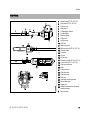
Main Parts
1
2
3
4
5
6
7
8
9
10
11
12
13
14
15
16
17
18
19
20
21
22
23
24
25
26
27
28
#
HT 100, HT 101, HT 130, HT 131
Handle hose (HT 100, HT 130)
Rigid shaft (HT 100, HT 130)
Carrying ring
Slide control
Throttle trigger lockout
Throttle trigger
Spark plug boot
Choke knob
Air filter cover
Fuel tank
Machine support
Machine support (HT 130, HT 131)
Oilomatic chain
Guide bar
Oil tank
Oil filler cap
Telescoping shaft (HT 101, HT 131)
Clamp screw (HT 101, HT 131)
Chain sprocket cover
Hook
Chain scabbard
Chain sprocket
Chain tensioner
Tank cap
Carburetor adjusting screws
Manual fuel pump
Starter grip
Muffler (some versions with spark
arresting screen)
Serial number
37
English
HT 130, HT 131
Specifications
31.4 cc
40 mm
25 mm
1.05 kW (1.4 bhp)
at 7,000 rpm
2,800 rpm
Displacement:
Bore:
Stroke:
Engine power to
ISO 8893:
Idle speed:
Cut-off speed
(rated):
Max. output shaft
speed (chain
sprocket):
Valve clearance
Inlet valve:
Exhaust valve:
10,200 rpm
Ignition System
Engine
STIHL single cylinder four-stroke engine
with mixture lubrication
HT 100, HT 101
Displacement:
Bore:
Stroke:
Engine power to
ISO 8893:
Idle speed:
Cut-off speed
(rated):
Max. output shaft
speed (chain
sprocket):
Valve clearance
Inlet valve:
Exhaust valve:
8,290 rpm
0.10 mm
0.10 mm
Weight
36.3 cc
43 mm
25 mm
1.4 kW (1.9 bhp)
at 8,500 rpm
2,800 rpm
dry, without bar and chain
HT 100:
5.5 kg
HT 101:
7.6 kg
HT 130:
5.7 kg
HT 131:
7.8 kg
10,200 rpm
Cutting Attachment
10,500 rpm
Actual cutting length may be less than
the specified length
0.10 mm
0.10 mm
Rollomatic E Mini guide bar
Cutting length:
Pitch:
Groove width:
30 cm
3/8" P (9.32 mm)
1.1 mm
Electronic magneto ignition
Rollomatic E Mini Light guide bars
Spark plug (resistor
type):
HT 100, HT 101:
Bosch USR 7 AC
HT 130, HT 131:
NGK CMR 6 H
Electrode gap:
0.5 mm
Cutting length:
Pitch:
Groove width:
Fuel System
All position diaphragm carburetor with
integral fuel pump
Fuel tank capacity:
530 cc (0.53 l)
Chain Lubrication
25, 30 cm
3/8" P (9.32 mm)
1.1 mm
3/8" P chains
Picco Micro Mini 3 (61 PMM3)
Type 3610
Pitch:
3/8" P (9.32 mm)
Drive link gauge:
1.1 mm
Chain sprocket
6-tooth for 3/8" P
7-tooth for 3/8" P
Fully automatic, speed-controlled oil
pump with rotary piston
Oil tank capacity:
38
220 cc (0.22 l)
HT 100, HT 101, HT 130, HT 131
English
Noise and Vibration Data
Noise and vibration data measurements
include idling and rated maximum speed
with the same duration of exposure.
For further details on compliance with
Vibration Directive 2002/44/EC see
www.stihl.com/vib/
Sound pressure level Lpeq to ISO 11201
HT 100:
HT 101:
HT 130:
HT 131:
89 dB(A)
89 dB(A)
92 dB(A)
93 dB(A)
Sound power level Lweq to ISO 3744
HT 100:
HT 101:
HT 130:
HT 131:
101 dB(A)
101 dB(A)
106 dB(A)
106 dB(A)
Vibration measurement ahv,eq to
EN ISO 11680-1
HT 100, HT 130
Shaft:
HT 100
HT 130
Control handle:
HT 100
HT 130
4.0 m/s2
4.3 m/s2
4.7 m/s2
6.0 m/s2
HT 100, HT 101, HT 130, HT 131
HT 101, HT 131
Shaft compressed:
HT 101
HT 131
Control handle:
HT 101
HT 131
Shaft fully extended:
HT 101
HT 131
Control handle:
HT 101
HT 131
Maintenance and Repairs
3.7 m/s2
3.0 m/s2
5.5 m/s2
4.7 m/s2
7.5 m/s2
3.4 m/s2
4.9 m/s2
4.7 m/s2
Users of this machine may only carry out
the maintenance and service work
described in this user manual. All other
repairs must be carried out by a
servicing dealer.
STIHL recommends that you have
servicing and repair work carried out
exclusively by an authorized STIHL
servicing dealer. STIHL dealers are
regularly given the opportunity to attend
training courses and are supplied with
the necessary technical information.
The K-factor in accordance with
Directive 2006/42/EC is 2.5 dB(A) for
the sound pressure level and sound
power level; the K-factor in accordance
with Directive 2006/42/EC is 2.0 m/s2
for the vibration measurement.
When repairing the machine, only use
replacement parts which have been
approved by STIHL for this power tool or
are technically identical. Only use highquality replacement parts in order to
avoid the risk of accidents and damage
to the machine.
REACH
STIHL recommends the use of original
STIHL replacement parts.
REACH is an EC regulation and stands
for the Registration, Evaluation,
Authorisation and Restriction of
Chemical substances.
Original STIHL parts can be identified by
the STIHL part number, the {
logo and the STIHL parts symbol K
(the symbol may appear alone on small
parts).
For information on compliance with the
REACH regulation (EC) No. 1907/2006
see www.stihl.com/reach.
39
English
Disposal
EC Declaration of Conformity
Observe all country-specific waste
disposal rules and regulations.
ANDREAS STIHL AG & Co. KG
Badstr. 115
D-71336 Waiblingen
000BA073 KN
confirms that the product described
below
STIHL products must not be thrown in
the garbage can. Take the product,
accessories and packaging to an
approved disposal site for environmentfriendly recycling.
Contact your STIHL servicing dealer for
the latest information on waste disposal.
Category:
Make:
Model:
Pole pruners
STIHL
HT 100
HT 101
HT 130
HT 131
Serial identification: 4182
Displacement
HT 100:
31.4 cc
HT 101:
31.4 cc
HT 130:
36.3 cc
HT 131:
36.3 cc
conforms to the provisions of Directives
2006/42/EC and 2004/108/EC and has
been developed and manufactured in
compliance with the following standards
in the versions valid at the time of
production:
Certification No.
HT 100:
M6 03 06 10127 214
HT 101:
M6 03 06 10127 212
HT 130:
M6 05 12 10127 272
HT 131:
M6 06 07 10127 291
Technical documents deposited at:
ANDREAS STIHL AG & Co. KG
Produktzulassung (Product Licensing)
The year of manufacture and serial
number are applied to the product.
Done at Waiblingen, 15.08.2014
ANDREAS STIHL AG & Co. KG
Thomas Elsner
Director Group Product Management
EN ISO 11680-1, EN 55012,
EN 61000-6-1
The EC type examination was carried
out by
TÜV Süd Product Service GmbH
(NB 0123)
Ridlerstrasse 65
D-80339 Munich
40
HT 100, HT 101, HT 130, HT 131
0458-246-0121-E
englisch
G
www.stihl.com
*04582460121E*
0458-246-0121-E