1
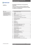
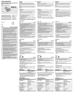
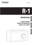
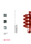
070670_Beipackzettel_VS18-VS26
10.5.2007
15:01 Uhr
Seite 1
VALVE ISLANDS VS18 / VS26 SERIES
GB
DE
INSTALLATION
INSTALLATION DATA
TECHNICAL DATA
Lubrication: Valves will function reliably when they are
supplied with clean dry air either lubricated or nonlubricated. If the air supply is lubricated, then lubrication must be supplied for the life of the product.
Medium: Compressed air, filtered (40 μm), lubricated or
non-lubricated
Maximum operating pressure:
10 bar: VS**S models and VS**G solenoid pilot actuated
valves with internal pilot supply
16 bar: VS**G solenoid pilot actuated valves with external pilot supply
Ambient temperature: -15°C* ... +50°C
* Consult our technical service for use below +2°C.
SAFETY NOTES
• Always switch off the air supply and unplug all
electrical connextions before performing any
maintenance.
• Ensure the machine is in a safe condition before
operating manual overrides.
• All VS18/VS26 24V DC products are designed to be
used with a protective extra low voltage (PELV) power
supply (UL class II supply only).
• All VS18/VS26 115V AC products correspond to the
protection class I. Connection of the protective earth
(PE) ground is required.
ATEX: Please review all ATEX data and notes in the
maintenance and instruction booklet to eliminate any
risks, allowing for safe function of the valve island.
Vibration: In applications where there is significant
vibration, the axis of the spool (longitudinal axis of the
valve) should be at 90° to the direction of the motion.
Tightening torque: To avoid damaging the product,
please make sure that the maximum torque values are
not exceeded. The maximum torques are specified in the
maintenance and instruction booklet.
(see overleaf)
Function
Port
Main/internal pilot air supply
1
Exhaust
3+5
Outlet
2+4
External pilot air supply (if used)
12/14
Collected exhaust of pilot valves
82/84
Note: Never plug port 82/84. Plugging this port will cause valves
to malfunction.
See warning notes overleaf.
Pin
no.
1)
Pin
no.
Wire colour
Socket
Pilot
Station
1
2
3
4
5
6
7
8
9
white
brown
green
yellow
grey
pink
blue
red
black
Solenoid 1-a
Solenoid 2-a
Solenoid 3-a
Solenoid 4-a
Solenoid 1-b
Solenoid 2-b
Solenoid 3-b
Solenoid 4-b
Common
14
14
14
14
12
12
12
12
1-
1
2
3
4
1
2
3
4
-
D-Sub 15-pin 1)
Pin
no.
Wire colour
Socket
Pilot
Station
1
2
3
4
5
6
7
8
9
10
11
12
13
14
15
white
brown
green
yellow
grey
pink
blue
red
black
violet
grey/pink
red/blue
white/green
brown/green
white/yellow
Solenoid 1-a
Solenoid 2-a
Solenoid 3-a
Solenoid 4-a
Solenoid 5-a
Solenoid 6-a
Solenoid 7-a
Solenoid 1-b
Solenoid 2-b
Solenoid 3-b
Solenoid 4-b
Solenoid 5-b
Solenoid 6-b
Solenoid 7-b
Common
14
14
14
14
14
14
14
12
12
12
12
12
12
12
1-
1
2
3
4
5
6
7
1
2
3
4
5
6
7
-
D-Sub 25-pin 1)
Pin
no.
Wire colour
Socket
Pilot
Station
1
2
3
4
5
6
7
8
9
10
11
12
13
14
15
16
17
18
19
20
21
22
23
24
25
white
brown
green
yellow
grey
pink
blue
red
black
violet
grey/pink
red/blue
white/green
brown/green
white/yellow
yellow/brown
white/grey
grey/brown
white/pink
pink/brown
white/blue
brown/blue
white/red
brown/red
white/black
Solenoid 1-a
Solenoid 2-a
Solenoid 3-a
Solenoid 4-a
Solenoid 5-a
Solenoid 6-a
Solenoid 7-a
Solenoid 8-a
Solenoid 9-a
Solenoid 10-a
Solenoid 11-a
Solenoid 12-a
Common
Solenoid 1-b
Solenoid 2-b
Solenoid 3-b
Solenoid 4-b
Solenoid 5-b
Solenoid 6-b
Solenoid 7-b
Solenoid 8-b
Solenoid 9-b
Solenoid 10-b
Solenoid 11-b
Solenoid 12-b
14
14
14
14
14
14
14
14
14
14
14
14
12
12
12
12
12
12
12
12
12
12
12
12
1
2
3
4
5
6
7
8
9
10
11
12
1
2
3
4
5
6
7
8
9
10
11
12
1) Colour code according to DIN 47100.
2) The Norgren D-Sub 44-pin cables do not have 44 wires, but only
34 wires. Therefore, the wires associated with pins 1 through
32 are according to DIN 47100, wires 43 and 44 differ from the
standard and are coloured in green/black and yellow/black.
For Fieldbus data please refer to data sheets and maintenance
and instruction booklet!
1
2
3
4
5
6
7
8
9
10
11
12
13
14
15
16
17
18
19
20
21
22
23
24
25
26
27
28
29
30
31
32
33
34
35
36
37
38
39
40
41
42
43
44
Wire colour
white
brown
green
yellow
grey
pink
blue
red
black
violet
grey/pink
red/blue
white/green
brown/green
white/yellow
yellow/brown
white/grey
grey/brown
white/pink
pink/brown
white/blue
brown/blue
white/red
brown/red
white/black
brown/black
grey/green
yellow/grey
pink/green
yellow/pink
green/blue
yellow/blue
blue/black 2)
red/black 2)
Detaillierte Angaben entnehmen Sie bitte den Datenblättern (VS18: 5.4.159; VS26: 5.4.160) und dem VS18/
VS26 Handbuch (Nr. VS2672926-KG00). Diese Unterlagen finden Sie auf der CD-ROM, welche der Ventilinsel
beiliegt (nur bei Feldbus oder ATEX Ventilinseln).
Andernfalls kontaktieren Sie bitte Ihre lokale Norgren
Vertretung.
TECHNISCHE DATEN
Medium: Gefilterte Druckluft (40 μm), geölt oder ungeölt
Maximaler Betriebsdruck:
10 bar: VS**S Ventile und VS**G Ventile mit interner
Steuerluftversorgung
16 bar: VS**G Ventile mit externer Steuerluftversorgung
Umgebungstemperatur: -15°C* ... +50°C
• Schalten Sie die Druckluftzufuhr ab, bevor Sie die
Luftanschlüsse lösen oder Ventile montieren/
demontieren.
• Stellen Sie sicher, dass sich die Maschine in einem
sicheren Zustand befindet, bevor Sie die Handhilfsbetätigungen aktivieren.
• Alle VS18/VS26 Ventilinseln mit 24V DC sind zur
Verwendung mit einer Sicherheitskleinspannung
(PELV) vorgesehen (UL class II supply only).
• Alle VS18/VS26 Ventilinseln mit 115V AC entsprechen
der Schutzklasse I und müssen an einer Schutzerde
(PE) angeschlossen werden.
ANSCHLUSSBELEGUNG DER MULTIPOL-STECKER:
Socket
Pilot
Solenoid 1-a
Solenoid 2-a
Solenoid 3-a
Solenoid 4-a
Solenoid 5-a
Solenoid 6-a
Solenoid 7-a
Solenoid 8-a
Solenoid 9-a
Solenoid 10-a
Solenoid 11-a
Solenoid 12-a
Solenoid 13-a
Solenoid 14-a
Solenoid 15-a
Solenoid 1-b
Solenoid 2-b
Solenoid 3-b
Solenoid 4-b
Solenoid 5-b
Solenoid 6-b
Solenoid 7-b
Solenoid 8-b
Solenoid 9-b
Solenoid 10-b
Solenoid 11-b
Solenoid 12-b
Solenoid 13-b
Solenoid 14-b
Solenoid 15-b
Solenoid 16-a
Solenoid 16-b
not used
not used
not used
not used
not used
not used
not used
not used
not used
not used
Common
Common
14
14
14
14
14
14
14
14
14
14
14
14
14
14
14
12
12
12
12
12
12
12
12
12
12
12
12
12
12
12
14
12
-
Station
1
2
3
4
5
6
7
8
9
10
11
12
13
14
15
1
2
3
4
5
6
7
8
9
10
11
12
13
14
15
16
16
-
M23 19-pin
Pin
no.
Wire colour
Socket
Pilot
1
2
3
4
5
6
7
8
9
10
11
12
13
14
15
16
17
18
19
white
brown (thin)
green
yellow
grey
blue (thick)
blue (thin)
red
black
violet
grey/pink
yellow/green
white/green
brown/green
white/yellow
yellow/brown
pink
red/blue
brown (thick)
Solenoid 8-a
Solenoid 6-a
Solenoid 4-a
Solenoid 2-b
Solenoid 2-a
Common
Solenoid 1-b
Solenoid 3-b
Solenoid 5-b
Solenoid 7-b
Solenoid 7-a
Earth
Solenoid 6-b
Solenoid 4-b
Solenoid 1-a
Solenoid 3-a
Solenoid 5-a
Solenoid 8-b
not used
14
14
14
12
14
12
12
12
12
14
12
12
14
14
14
12
-
Station
8
6
4
2
2
1
3
5
7
7
6
4
1
3
5
8
-
(siehe auch Rückseite)
D-Sub 9-polig
Stift- Farbcode
Nr.
Anschluss
Seite
Ventilplatz
1
2
3
4
5
6
7
8
9
Pilotventil 1-a
Pilotventil 2-a
Pilotventil 3-a
Pilotventil 4-a
Pilotventil 1-b
Pilotventil 2-b
Pilotventil 3-b
Pilotventil 4-b
Gemeinsam
14
14
14
14
12
12
12
12
1-
1
2
3
4
1
2
3
4
-
Stift- Farbcode
Nr.
Anschluss
Seite
Ventilplatz
1
2
3
4
5
6
7
8
9
10
11
12
13
14
15
Pilotventil 1-a
Pilotventil 2-a
Pilotventil 3-a
Pilotventil 4-a
Pilotventil 5-a
Pilotventil 6-a
Pilotventil 7-a
Pilotventil 1-b
Pilotventil 2-b
Pilotventil 3-b
Pilotventil 4-b
Pilotventil 5-b
Pilotventil 6-b
Pilotventil 7-b
Gemeinsam
14
14
14
14
14
14
14
12
12
12
12
12
12
12
1-
1
2
3
4
5
6
7
1
2
3
4
5
6
7
-
Stift- Farbcode
Nr.
Anschluss
Seite
Ventilplatz
1
2
3
4
5
6
7
8
9
10
11
12
13
14
15
16
17
18
19
20
21
22
23
24
25
Pilotventil 1-a
Pilotventil 2-a
Pilotventil 3-a
Pilotventil 4-a
Pilotventil 5-a
Pilotventil 6-a
Pilotventil 7-a
Pilotventil 8-a
Pilotventil 9-a
Pilotventil 10-a
Pilotventil 11-a
Pilotventil 12-a
Gemeinsam
Pilotventil 1-b
Pilotventil 2-b
Pilotventil 3-b
Pilotventil 4-b
Pilotventil 5-b
Pilotventil 6-b
Pilotventil 7-b
Pilotventil 8-b
Pilotventil 9-b
Pilotventil 10-b
Pilotventil 11-b
Pilotventil 12-b
14
14
14
14
14
14
14
14
14
14
14
14
12
12
12
12
12
12
12
12
12
12
12
12
1
2
3
4
5
6
7
8
9
10
11
12
1
2
3
4
5
6
7
8
9
10
11
12
weiss
braun
grün
gelb
grau
rosa
blau
rot
schwarz
D-Sub 15-polig 1)
weiss
braun
grün
gelb
grau
rosa
blau
rot
schwarz
violett
grau/rosa
rot/blau
weiss/grün
braun/grün
weiss/gelb
D-Sub 25-polig 1)
weiss
braun
grün
gelb
grau
rosa
blau
rot
schwarz
violett
grau/rosa
rot/blau
weiss/grün
braun/grün
weiss/gelb
gelb/braun
weiss/grau
grau/braun
weiss/rosa
rosa/braun
weiss/blau
braun/blau
weiss/rot
braun/rot
weiss/schwarz
MONTAGEHINWEISE
ATEX: Zur sicheren Funktion und zur gefahrfreien Verwendung dieser Ventilinsel müssen die zulässigen Daten und
Hinweise des VS18/VS26 Handbuches beachtet werden.
Schmierung: Die Ventile arbeiten mit sauberer, trockener oder geölter Druckluft zuverlässig. Wurden die
Ventile einmal mit geölter Druckluft betrieben, ist eine
Umstellung auf ungeölte Druckluft nicht mehr zulässig.
Vibration: Anwendungen, bei denen starke Beschleunigungskräfte (Vibrationen etc.) auftreten, erfordern
eine Ventilmontage, bei der sich der Kolbenschieber im
Ventil (Längsachse des Ventils) im 90° Winkel zur
auftretenden Kraft befindet.
Kennzeichnung der pneumatischen Anschlüsse:
Funktion
1) Der Farbcode entspricht DIN 47100.
2) Die Norgren D-Sub Stecker 44-polig haben anstatt 44 nur 34
Drähte. Aus diesem Grund entsprechen die Leitungen, die mit
den Stiften 1 bis 32 verbunden sind, DIN 47100. Die Leitungen 43
und 44 unterscheiden sich vom Standard und sind in grün/
schwarz und gelb/schwarz gefärbt.
Anschlussbelegungen der Feldbus-Stecker entnehmen Sie bitte
den entsprechenden Datenblättern oder dem VS18/VS26 Handbuch!
Anschluss
Drucklufteinspeisung/interne Steuerluft
1
Entlüftung
3+5
Arbeitsanschlüsse
2+4
Externe Steuerluft (falls verwendet)
12/14
Gesammelte Pilotventilentlüftung
82/84
Achtung: Verschliessen Sie niemals den Anschluss 82/84, da dies
zu einer Fehlfunktion des Ventils führen würde.
Pour des instructions détaillées consultez les data
sheets (VS18: 5.4.159; VS26: 5.4.160) et la notice de
maintenance et d’installation VS18/VS26 (réf. no.
VS2672926-KG00) disponible sur le CD-Rom livré avec
l’îlot de distributeurs (uniquement Fieldbus ou ATEX).
Vous pouvez également consulter votre fournisseur
local NORGREN.
DONNEES TECHNIQUES
Fluide: Air comprimé, filtré (40 μm), lubrifié ou non.
Pression maximum d’utilisation:
10 bar: modèles VS**S et distributeurs VS**G à commande électropneumatique avec pilotage interne.
16 bar: distributeurs VS**G à commande électropneumatique avec pilotage externe.
Température ambiante: -15°C* ... +50°C
*Consultez-nous pour températures inférieures à +2°C.
NOTES DE SECURITE
• Couper l’air d’alimentation avant de déconnecter la
conduite principale ou les distributeurs des îlots.
• Assurez-vous que la machine est en position de sécurité avant d’actionner les commandes manuelles.
• Tous les produits VS18/VS26 24V c.c. sont conçus
pour utilisation avec une alimentation de protection à
très basse tension (PELV, UL class II supply only).
• Tous les produits VS18/VS26 115V c.a. correspondent
au degré de protection classe I. Le raccordement à la
terre (PE) est nécessaire.
INSTALLATION
ATEX: Veuillez vérifier toutes les données et les notes
ATEX dans les notices d’entretien et d’installation afin
d’éviter tout risque, permettant un fonctionnement en
sécurité de l’îlot de vannes.
Lubrification: Ces distributeurs fonctionnent en toute
fiabilité avec de l’air propre et sec, lubrifié ou non. Si
l’air d’alimentation est lubrifié, la lubrification doit continuer pendant toute la durée de vie des distributeurs.
Vibrations: Lorsqu’une application provoque d’importantes vibrations, l’axe de la bobine (axe longitudinal du
distributeur) sera monté à 90° par rapport à la direction
du mouvement.
Couple de serrage: Pour éviter la destruction du produit
s’assurer que les valeurs maximales du couple de
serrage ne sont pas dépassées. Les couples maxi sont
indiqués dans le manuel de maintenance.
Identification des orifices:
Fonction
Orifice
Alimentation principale/air de pilotage interne
1
Echappement
3+5
Sorties
2+4
Air de pilotage externe (si utilisé)
12/14
Echappement collecté des pilotes
82/84
Note: Ne jamais obturer 82/84. Obturer cet orifice peut causer un
mauvais fonctionnement des distributeurs.
Voir avertissement au verso.
Warnhinweise siehe Rückseite.
D-Sub 44-polig 1)
Stift- Farbcode
Nr.
1)
ILOTS DE DISTRIBUTEURS SERIESVS18 / VS26
INSTALLATION
Drehmomente: Um Beschädigungen zu vermeiden, dürfen die vorgegebenen Werte nicht überschritten werden.
Die Anzugsdrehmomente sind im VS18/VS26 Handbuch
angegeben.
* Unter +2°C bitte Luftbeschaffenheit beachten.
SICHERHEITSHINWEISE
Port identification:
D-Sub 44-pin 1)
PIN ASSIGNMENT MULTIPOLE CONNECTORS:
VS2672909-KG00C_04/07
FR
EINBAU- UND WARTUNGSVORSCHRIFT
For detailed instructions see data sheets (VS18: 5.4.159;
VS26: 5.4.160) and VS18/VS26 maintenance and instruction booklet (ref. no. VS2672926-KG00) available from
CD-ROM supplied with valve island (Fieldbus or ATEX
only). Alternatively contact local Norgren representative.
D-Sub 9-pin
VS18 / VS26 VENTILINSELN
1
2
3
4
5
6
7
8
9
10
11
12
13
14
15
16
17
18
19
20
21
22
23
24
25
26
27
28
29
30
31
32
33
34
35
36
37
38
39
40
41
42
43
44
weiss
braun
grün
gelb
grau
rosa
blau
rot
schwarz
violett
grau/rosa
rot/blau
weiss/grün
braun/grün
weiss/gelb
gelb/braun
weiss/grau
grau/braun
weiss/rosa
rosa/braun
weiss/blau
braun/blau
weiss/rot
braun/rot
weiss/schwarz
braun/schwarz
grau/grün
gelb/grau
rosa/grün
gelb/rosa
grün/blau
gelb/blau
blau/schwarz 2)
rot/schwarz 2)
Anschluss
Seite
Ventilplatz
Pilotventil 1-a
Pilotventil 2-a
Pilotventil 3-a
Pilotventil 4-a
Pilotventil 5-a
Pilotventil 6-a
Pilotventil 7-a
Pilotventil 8-a
Pilotventil 9-a
Pilotventil 10-a
Pilotventil 11-a
Pilotventil 12-a
Pilotventil 13-a
Pilotventil 14-a
Pilotventil 15-a
Pilotventil 1-b
Pilotventil 2-b
Pilotventil 3-b
Pilotventil 4-b
Pilotventil 5-b
Pilotventil 6-b
Pilotventil 7-b
Pilotventil 8-b
Pilotventil 9-b
Pilotventil 10-b
Pilotventil 11-b
Pilotventil 12-b
Pilotventil 13-b
Pilotventil 14-b
Pilotventil 15-b
Pilotventil 16-a
Pilotventil 16-b
n.v.
n.v.
n.v.
n.v.
n.v.
n.v.
n.v.
n.v.
n.v.
n.v.
Gemeinsam
Gemeinsam
14
14
14
14
14
14
14
14
14
14
14
14
14
14
14
12
12
12
12
12
12
12
12
12
12
12
12
12
12
12
14
12
-
1
2
3
4
5
6
7
8
9
10
11
12
13
14
15
1
2
3
4
5
6
7
8
9
10
11
12
13
14
15
16
16
-
Stift- Farbcode
Nr.
Anschluss
Seite
Ventilplatz
1
2
3
4
5
6
7
8
9
10
11
12
13
14
15
16
17
18
19
Pilotventil 8-a
Pilotventil 6-a
Pilotventil 4-a
Pilotventil 2-b
Pilotventil 2-a
Gemeinsam
Pilotventil 1-b
Pilotventil 3-b
Pilotventil 5-b
Pilotventil 7-b
Pilotventil 7-a
Erde
Pilotventil 6-b
Pilotventil 4-b
Pilotventil 1-a
Pilotventil 3-a
Pilotventil 5-a
Pilotventil 8-b
n.v.
14
14
14
12
14
12
12
12
12
14
12
12
14
14
14
12
-
8
6
4
2
2
1
3
5
7
7
6
4
1
3
5
8
-
M23 19-polig
weiss
braun (dünn)
grün
gelb
grau
blau (dick)
blau (dünn)
rot
schwarz
violett
grau/rosa
gelb/grün
weiss/grün
braun/grün
weiss/gelb
gelb/braun
rosa
rot/blau
braun (dick)
DÉSIGNATION DES BROCHES DANS LES CONNECTEURS
MULITPOLE:
(voir au verso)
Connecteur Sub-D 9 broches 1)
Broche Couleur
no.
du câble
à relier à
Pilote
Station
1
2
3
4
5
6
7
8
9
Bobine 1-a
Bobine 2-a
Bobine 3-a
Bobine 4-a
Bobine 1-b
Bobine 2-b
Bobine 3-b
Bobine 4-b
Commun
14
14
14
14
12
12
12
12
1-
1
2
3
4
1
2
3
4
-
blanc
marron
vert
jaune
gris
rose
bleu
rouge
noir
Connecteur Sub-D 15 broches 1)
Broche Couleur
no.
du câble
à relier à
Pilote
Station
1
2
3
4
5
6
7
8
9
10
11
12
13
14
15
Bobine 1-a
Bobine 2-a
Bobine 3-a
Bobine 4-a
Bobine 5-a
Bobine 6-a
Bobine 7-a
Bobine 1-b
Bobine 2-b
Bobine 3-b
Bobine 4-b
Bobine 5-b
Bobine 6-b
Bobine 7-b
Commun
14
14
14
14
14
14
14
12
12
12
12
12
12
12
1-
1
2
3
4
5
6
7
1
2
3
4
5
6
7
-
blanc
marron
vert
jaune
gris
rose
bleu
rouge
noir
violet
gris/rose
rouge/bleu
blanc/vert
marron/vert
blanc/jaune
Connecteur Sub-D 25 broches 1)
Broche Couleur
no.
du câble
à relier à
Pilote
Station
1
2
3
4
5
6
7
8
9
10
11
12
13
14
15
16
17
18
19
20
21
22
23
24
25
Bobine 1-a
Bobine 2-a
Bobine 3-a
Bobine 4-a
Bobine 5-a
Bobine 6-a
Bobine 7-a
Bobine 8-a
Bobine 9-a
Bobine 10-a
Bobine 11-a
Bobine 12-a
Commun
Bobine 1-b
Bobine 2-b
Bobine 3-b
Bobine 4-b
Bobine 5-b
Bobine 6-b
Bobine 7-b
Bobine 8-b
Bobine 9-b
Bobine 10-b
Bobine 11-b
Bobine 12-b
14
14
14
14
14
14
14
14
14
14
14
14
12
12
12
12
12
12
12
12
12
12
12
12
1
2
3
4
5
6
7
8
9
10
11
12
1
2
3
4
5
6
7
8
9
10
11
12
blanc
marron
vert
jaune
gris
rose
bleu
rouge
noir
violet
gris/rose
rouge/bleu
blanc/vert
marron/vert
blanc/jaune
jaune/marron
blanc/gris
gris/marron
blanc/rose
rose/marron
blanc/bleu
marron/bleu
blanc/rouge
marron/rouge
blanc/noir
1) Couleur de câble conforme à la norme DIN 47100.
2) Le câble du connecteur Sub-D 44 n’a pas 44 fils mais 34 seulement. Les fils des broches 1 à 32 sont conformes à la norme DIN
47100, les fils des broches 43 et 44 diffèrent et sont vert/noir et
jaune/noir.
Pour Fieldbus consultez les data sheets et les notices de
maintenance et d’utilisation!
Connecteur Sub-D 44 broches
Broche Couleur
no.
du câble
à relier à
Pilote
Station
1
2
3
4
5
6
7
8
9
10
11
12
13
14
15
16
17
18
19
20
21
22
23
24
25
26
27
28
29
30
31
32
33
34
35
36
37
38
39
40
41
42
43
44
Bobine 1-a
Bobine 2-a
Bobine 3-a
Bobine 4-a
Bobine 5-a
Bobine 6-a
Bobine 7-a
Bobine 8-a
Bobine 9-a
Bobine 10-a
Bobine 11-a
Bobine 12-a
Bobine 13-a
Bobine 14-a
Bobine 15-a
Bobine 1-b
Bobine 2-b
Bobine 3-b
Bobine 4-b
Bobine 5-b
Bobine 6-b
Bobine 7-b
Bobine 8-b
Bobine 9-b
Bobine 10-b
Bobine 11-b
Bobine 12-b
Bobine 13-b
Bobine 14-b
Bobine 15-b
Bobine 16-a
Bobine 16-b
non-utilisé
non-utilisé
non-utilisé
non-utilisé
non-utilisé
non-utilisé
non-utilisé
non-utilisé
non-utilisé
non-utilisé
Commun
Commun
14
14
14
14
14
14
14
14
14
14
14
14
14
14
14
12
12
12
12
12
12
12
12
12
12
12
12
12
12
12
14
12
-
1
2
3
4
5
6
7
8
9
10
11
12
13
14
15
1
2
3
4
5
6
7
8
9
10
11
12
13
14
15
16
16
-
blanc
marron
vert
jaune
gris
rose
bleu
rouge
noir
violet
gris/rose
rouge/bleu
blanc/vert
marron/vert
blanc/jaune
jaune/marron
blanc/gris
gris/marron
blanc/rose
rose/marron
blanc/bleu
marron/bleu
blanc/rouge
marron/rouge
blanc/noir
marron/noir
gris/vert
jaune/gris
rose/vert
jaune/rose
vert/bleu
jaune/bleu
bleu/noir 2)
rouge/noir 2)
Connecteur M23 19 broches
Broche Couleur
no.
du câble
à relier à
Pilote
Station
1
2
3
4
5
6
7
8
9
10
11
12
13
14
15
16
17
18
19
Bobine 8-a
Bobine 6-a
Bobine 4-a
Bobine 2-b
Bobine 2-a
Commun
Bobine 1-b
Bobine 3-b
Bobine 5-b
Bobine 7-b
Bobine 7-a
Terre
Bobine 6-b
Bobine 4-b
Bobine 1-a
Bobine 3-a
Bobine 5-a
Bobine 8-b
non-utilisé
14
14
14
12
14
12
12
12
12
14
12
12
14
14
14
12
-
8
6
4
2
2
1
3
5
7
7
6
4
1
3
5
8
-
blanc
marron (mince)
vert
jaune
gris
bleu (épais)
bleu (mince)
rouge
noir
violet
gris/rose
jaune/vert
blanc/vert
marron/vert
blanc/jaune
jaune/marron
rose
rouge/bleu
marron (épais)
070670_Beipackzettel_VS18-VS26
10.5.2007
15:01 Uhr
Seite 2
ISLAS DE VÁLVULAS SERIE VS18 / VS26
ES
ISOLE DI VALVOLE VS18 / VS26
IT
INSTALACIÓN
INSTALLAZIONE
Para instrucciones detalladas, ver hojas técnicas
(VS18: 5.4.159; VS26: 5.4.160) o el manual de instrucciones y mantenimiento (VS2672926-KG00) en el
CD-ROM suministrado con la isla de válvulas (sólo
Fieldbus o ATEX). Si lo prefiere, puede contactar
directamente con su compañía Norgren local.
INSTALACIÓN
DATOS TÉCNICOS
Lubricación: Las válvulas funcionarán de forma más fiable
si se les suministra aire limpio y seco, lubricado o no lubricado. Si el aire que se suministra está lubricado, entonces debe lubricarse durante toda la vida del producto.
Fluido: Aire comprimido, filtrado (40 μm) lubricado o no
lubricado
Presión de trabajo máxima:
10 bar: Modelos VS**S y modelos VS**G con
accionamiento eléctrico y suministro interno
16 bar: Modelos VS**G con accionamiento eléctrico y
suministro externo
Temperatura ambiente: -15°C* ... +50°C
* Consultar con nuestro Servicio Técnico para temperaturas inferiores a +2°C.
NOTAS DE SEGURIDAD
• Desconectar el suministro de aire antes de extraer la
conexión principal neumática o las válvulas de la isla.
• Asegurarse que la máquina están en condiciones
seguras antes de accionar los mandos manuales.
• Todos los productos VS18/VS26 24V CC están
diseñados para utilizarse con una protección extra
de bajo voltaje (PELV, UL class II supply only).
• Todos los productos VS18/VS26 115V CA tienen
protección clase I. Se necesita una conexión de toma
tierra (PE).
ATEX: Tener en cuenta todas las notas y datos referentes
a la normativa ATEX del manual de instrucciones y mantenimiento para eliminar cualquier riesgo, permitiendo
así un funcionamiento seguro de la isla de válvulas.
Vibración: En aplicaciones donde haya una vibración
significativa, el eje de la corredera (eje longitudinal de la
válvula) debería estar a 90° de la dirección del
movimiento.
Apriete del giro: Para evitar dañar el producto, por favor, asegúrese de no exceder los valores máximos de
giro. Estos valores máximos están especificados en el
manual de instrucciones y mantenimiento.
Identificación de las vías:
Funcion
Via
Suministro de aire principal/interno
1
Escape
3+5
Salida
2+4
Suministro de aire externo (si se utiliza)
12/14
Escape conducido de las válvulas piloto
82/84
Nota: Nunca obstruir las vías 82/84. La obstrucción de estas vías
puede causar un mal funcionamiento de las válvulas.
Ver notas de advertencia a la derecha .
ASIGNACIÓN PIN DE LOS CONECTORES MULTIPOLO
(ver derecha)
N°
pin
Sub-conector 9-pin 1)
N°
pin
Color cable
Enchufe
Piloto
Estación
1
2
3
4
5
6
7
8
9
blanco
marrón
verde
amarillo
gris
rosa
azul
rojo
negro
Solenoide 1-a
Solenoide 2-a
Solenoide 3-a
Solenoide 4-a
Solenoide 1-b
Solenoide 2-b
Solenoide 3-b
Solenoide 4-b
Común
14
14
14
14
12
12
12
12
1-
1
2
3
4
1
2
3
4
-
Sub-conector 15-pin
Sub-conector 44-pin
1)
N°
pin
Color cable
Enchufe
Piloto
Estación
1
2
3
4
5
6
7
8
9
10
11
12
13
14
15
blanco
marrón
verde
amarillo
gris
rosa
azul
rojo
negro
violeta
gris/rosa
rojo/azul
blanco/verde
marrón/verde
blanco/amarillo
Solenoide 1-a
Solenoide 2-a
Solenoide 3-a
Solenoide 4-a
Solenoide 5-a
Solenoide 6-a
Solenoide 7-a
Solenoide 1-b
Solenoide 2-b
Solenoide 3-b
Solenoide 4-b
Solenoide 5-b
Solenoide 6-b
Solenoide 7-b
Común
14
14
14
14
14
14
14
12
12
12
12
12
12
12
1-
1
2
3
4
5
6
7
1
2
3
4
5
6
7
-
Sub-conector 25-pin 1)
N°
pin
Color cable
Enchufe
Piloto
Estación
1
2
3
4
5
6
7
8
9
10
11
12
13
14
15
16
17
18
19
20
21
22
23
24
25
blanco
marrón
verde
amarillo
gris
rosa
azul
rojo
negro
violeta
gris/rosa
rojo/azul
blanco/verde
marrón/verde
blanco/amarillo
amarillo/marrón
blanco/gris
gris/marrón
blanco/rosa
rosa/marrón
blanco/azul
marrón/azul
blanco/rojo
marrón/rojo
blanco/negro
Solenoide 1-a
Solenoide 2-a
Solenoide 3-a
Solenoide 4-a
Solenoide 5-a
Solenoide 6-a
Solenoide 7-a
Solenoide 8-a
Solenoide 9-a
Solenoide 10-a
Solenoide 11-a
Solenoide 12-a
Común
Solenoide 1-b
Solenoide 2-b
Solenoide 3-b
Solenoide 4-b
Solenoide 5-b
Solenoide 6-b
Solenoide 7-b
Solenoide 8-b
Solenoide 9-b
Solenoide 10-b
Solenoide 11-b
Solenoide 12-b
14
14
14
14
14
14
14
14
14
14
14
14
12
12
12
12
12
12
12
12
12
12
12
12
1
2
3
4
5
6
7
8
9
10
11
12
1
2
3
4
5
6
7
8
9
10
11
12
1) Código de colores según DIN 47100.
2) El conector Norgren Sub-D de 44 pin no tiene 44 hilos sino sólamente 34. Por tanto, los hilos asociados con los pins 1 hasta 32,
son según DIN 47100, los hilos 43 y 44 difieren del estándar y
son de color verde/negro y amarillo/negro.
Para información de Fieldbus, consultar hojas técnicas y manual
de instrucciones y mantenimiento.
VS2672909-KG00C_04/07
1
2
3
4
5
6
7
8
9
10
11
12
13
14
15
16
17
18
19
20
21
22
23
24
25
26
27
28
29
30
31
32
33
34
35
36
37
38
39
40
41
42
43
44
1)
Color cable
blanco
marrón
verde
amarillo
gris
rosa
azul
rojo
negro
violeta
gris/rosa
rojo/azul
blanco/verde
marrón/verde
blanco/amarillo
amarillo/marrón
blanco/gris
gris/marrón
blanco/rosa
rosa/marrón
blanco/azul
marrón/azul
blanco/rojo
marrón/rojo
blanco/negro
marrón/negro
gris/verde
amarillo/gris
rosa/verde
amarillo/rosa
verde/azul
amarillo/azul
azul/negro 2)
rojo/negro 2)
Per istruzioni dettagliate consultare i Fogli di Catalogo
delle (VS18: 5.4.159; VS26: 5.4.160) e i fogli di installazione
e manutenzione VS18/VS26 (no. VS2672926-KG00) disponibili sul CD Rom fornito unitamente alle isole di valvole
(Fieldbus o certificate ATEX). Alternativamente consultare
la rappresentanza Norgren del posto.
DATI DI INSTALLAZIONE
CARATTERISTICHE TECNICHE
Lubrificazione: Le valvole sono adatte al funzionamento
con aria essiccata, lubrificata o non lubrificata. Se la lubrificazione viene fornita alle valvole, questa deve essere
fornita in continuazione per garantire la durata della vita
prodotti.
Fluido: Aria Compressa, filtrata (40 μm), lubrificata o
non lubrificata
Massima pressione di Lavoro:
10 bar: Modelli VS**S e VS**G ad azionamento elettrico
con alimentazione interna
16 bar: VS**G ad azionamento elettrico con
alimentazione esterna
Temperatura Ambiente: -15°C* ... +50°C
* Consultare il nostro Servizio Tecnico per utilizzi al di sotto di +2°C.
INFORMAZIONI DI SICUREZZA
• Togliere l'aria compressa prima di rimuovere la
connessione di alimentazione o prima di rimuovere le
valvole dall'isola
• Accertare che la macchina sia in condizioni di sicurezza prima di azionare i comandi manuali delle valvole.
• Tutte le valvole della serie VS18/VS26 a 24V DC sono
progettati per funzionare con una tensione di alimentazione estremamente bassa (PELV) protective extra
low voltage (UL class II supply only).
• Tutte le valvole della serie VS18/VS26 a 115V AC
rispondono ai requisiti di protezione della classe I.
La messa a Terra (PE) di protezione è richiesta.
CONNESSIONI MULTIPOLARI: COLLEGAMENTI PIN
Enchufe
Piloto
Estación
Solenoide 1-a
Solenoide 2-a
Solenoide 3-a
Solenoide 4-a
Solenoide 5-a
Solenoide 6-a
Solenoide 7-a
Solenoide 8-a
Solenoide 9-a
Solenoide 10-a
Solenoide 11-a
Solenoide 12-a
Solenoide 13-a
Solenoide 14-a
Solenoide 15-a
Solenoide 1-b
Solenoide 2-b
Solenoide 3-b
Solenoide 4-b
Solenoide 5-b
Solenoide 6-b
Solenoide 7-b
Solenoide 8-b
Solenoide 9-b
Solenoide 10-b
Solenoide 11-b
Solenoide 12-b
Solenoide 13-b
Solenoide 14-b
Solenoide 15-b
Solenoide 16-a
Solenoide 16-b
No se utiliza
No se utiliza
No se utiliza
No se utiliza
No se utiliza
No se utiliza
No se utiliza
No se utiliza
No se utiliza
No se utiliza
Común
Común
14
14
14
14
14
14
14
14
14
14
14
14
14
14
14
12
12
12
12
12
12
12
12
12
12
12
12
12
12
12
14
12
-
1
2
3
4
5
6
7
8
9
10
11
12
13
14
15
1
2
3
4
5
6
7
8
9
10
11
12
13
14
15
16
16
-
M23-conector 19-pin
N°
pin
Color cable
Enchufe
Piloto
Estación
1
2
3
4
5
6
7
8
9
10
11
12
13
14
15
16
17
18
19
blanco
marrón (fino)
verde
amarillo
gris
azul (grueso)
azul (fino)
rojo
negro
violeta
gris/rosa
amarillo/verde
blanco/verde
marrón/verde
blanco/amarillo
amarillo/marrón
rosa
rojo/azul
marrón (grueso)
Solenoide 8-a
Solenoide 6-a
Solenoide 4-a
Solenoide 2-b
Solenoide 2-a
Común
Solenoide 1-b
Solenoide 3-b
Solenoide 5-b
Solenoide 7-b
Solenoide 7-a
Tierra
Solenoide 6-b
Solenoide 4-b
Solenoide 1-a
Solenoide 3-a
Solenoide 5-a
Solenoide 8-b
No se utiliza
14
14
14
12
14
12
12
12
12
14
12
12
14
14
14
12
-
8
6
4
2
2
1
3
5
7
7
6
4
1
3
5
8
-
(vedi destra)
Forma D 9 pin 1)
Pin
no.
Colore filo
Piedinatura
Pilota
ggio
Posta
valvola
1
2
3
4
5
6
7
8
9
bianco
marrone
verde
giallo
grigio
rosa
blue
rosso
nero
Solenoide 1-a
Solenoide 2-a
Solenoide 3-a
Solenoide 4-a
Solenoide 1-b
Solenoide 2-b
Solenoide 3-b
Solenoide 4-b
Comune
14
14
14
14
12
12
12
12
1-
1
2
3
4
1
2
3
4
-
Forma D 15 pin
1)
Pin
no.
Colore filo
Piedinatura
Pilota
ggio
Posta
valvola
1
2
3
4
5
6
7
8
9
10
11
12
13
14
15
bianco
marrone
verde
giallo
grigio
rosa
blue
rosso
nero
viola
grigio/rosa
rosso/blue
bianco/verde
marrone/verde
bianco/giallo
Solenoide 1-a
Solenoide 2-a
Solenoide 3-a
Solenoide 4-a
Solenoide 5-a
Solenoide 6-a
Solenoide 7-a
Solenoide 1-b
Solenoide 2-b
Solenoide 3-b
Solenoide 4-b
Solenoide 5-b
Solenoide 6-b
Solenoide 7-b
Comune
14
14
14
14
14
14
14
12
12
12
12
12
12
12
1-
1
2
3
4
5
6
7
1
2
3
4
5
6
7
-
Forma D 25 pin 1)
Pin
no.
Colore filo
Piedinatura
Pilota
ggio
Posta
valvola
1
2
3
4
5
6
7
8
9
10
11
12
13
14
15
16
17
18
19
20
21
22
23
24
25
bianco
marrone
verde
giallo
grigio
rosa
blue
rosso
nero
viola
grigio/rosa
rosso/blue
bianco/verde
marrone/verde
bianco/giallo
giallo/marrone
bianco/grigio
grigio/marrone
bianco/rosa
rosa/marrone
bianco/blue
marrone/blue
bianco/rosso
marrone/rosso
bianco/nero
Solenoide 1-a
Solenoide 2-a
Solenoide 3-a
Solenoide 4-a
Solenoide 5-a
Solenoide 6-a
Solenoide 7-a
Solenoide 8-a
Solenoide 9-a
Solenoide 10-a
Solenoide 11-a
Solenoide 12-a
Comune
Solenoide 1-b
Solenoide 2-b
Solenoide 3-b
Solenoide 4-b
Solenoide 5-b
Solenoide 6-b
Solenoide 7-b
Solenoide 8-b
Solenoide 9-b
Solenoide 10-b
Solenoide 11-b
Solenoide 12-b
14
14
14
14
14
14
14
14
14
14
14
14
12
12
12
12
12
12
12
12
12
12
12
12
1
2
3
4
5
6
7
8
9
10
11
12
1
2
3
4
5
6
7
8
9
10
11
12
1) Colore filo conforme alle DIN 47100.
2) I cavi Norgren Sub-D a 44 poli dispongono di 34 pin utili. Pertanto
i collegamenti associati ai pin 1-32 sono conformi alla normativa
DIN 47100, i collegamenti 43 e 44 si differenziano dallo standard
e sono di colore verde/nero, giallo/nero.
Per i sistemi Fieldbus fare riferimento ai fogli di catalogo e ai
fogli di installazione e manutenzione relativi.
ATEX: Per cortesia rileggete tutte le informazioni relative alle Norme ATEX nel manuale di installazione e
manutenzione per evitare qualsiasi tipo di rischio dando
al prodotto sicurezza applicativa.
PIN ASSIGNMENT MULTIPOLE CONNECTORS:
ANSCHLUSSBELEGUNG DER MULTIPOL-STECKER:
DESIGNATION DES BROCHES DANS LES CONNECTEURS MULTIPOLE:
ASIGNACIÓN PIN DE LOS CONECTORES MULTIPOLO:
CONNESSIONI MULTIPOLARI: COLLEGAMENTI PIN:
D-Sub 9-pin (male)
D-Sub 9-polig (Stift)
Sub-D 9 broches (mâle)
Sub-conector 9-pin (macho)
Forma D 9 pin (maschio)
D-Sub 15-pin (male)
D-Sub 25-pin (male)
D-Sub 15-polig (Stift)
D-Sub 25-polig (Stift)
Sub-D 15 broches (mâle)
Sub-D 25 broches (mâle)
Sub-conector 15-pin (macho) Sub-conector 25-pin (macho)
Forma D 15 pin (maschio)
Forma D 25 pin (maschio)
D-Sub 44-pin (male)
D-Sub 44-polig (Stift)
Sub-D 44-broches (mâle)
Sub-conector 44-pin (macho)
Forma D 44 pin (maschio)
Vibrazione: In applicazioni dove vi sia presenza di forti
vibrazioni, l'asse della valvola (l'asse del cassetto)
dovrebbe essere a 90° rispetto alla direzione del moto.
Coppia di serraggio: Per evitare danni al prodotto è
necessario che i valori massimi delle coppie non
vengano superati. Tali valori massimi sono specificati
nel manuale di istruzione e manutenzione.
Identificazione delle connessioni:
Funzione
Connessione
Alimentazione/pilotaggi interni
1
Scarico
3+5
Uscite
2+4
Alimentazioni esterne (se usate)
12/14
Convogliamento degli scarichi pilotaggi
82/84
Nota: Non chiudere le connessioni 82/84. La chiusura provoca il
funzionamento non corretto della valvola.
Vedi avviso d’attenzione alla destra.
M23 19-pin (male)
M23 19-polig (Stift)
M23 19 broches (mâle)
M23 19-pin (macho)
M23 9 pin (maschio)
Forma D 44 pin 1)
Pin
no.
Colore filo
Piedinatura
Pilota
ggio
Posta
valvola
1
2
3
4
5
6
7
8
9
10
11
12
13
14
15
16
17
18
19
20
21
22
23
24
25
26
27
28
29
30
31
32
33
34
35
36
37
38
39
40
41
42
43
44
bianco
marrone
verde
giallo
grigio
rosa
blue
rosso
nero
viola
grigio/rosa
rosso/blue
bianco/verde
marrone/verde
bianco/giallo
giallo/marrone
bianco/grigio
grigio/marrone
bianco/rosa
rosa/marrone
bianco/blue
marrone/blue
bianco/rosso
marrone/rosso
bianco/nero
marrone/nero
grigio/verde
giallo/grigio
rosa/verde
giallo/rosa
verde/blue
giallo/blue
blue/nero 2)
rosso/nero 2)
Solenoide 1-a
Solenoide 2-a
Solenoide 3-a
Solenoide 4-a
Solenoide 5-a
Solenoide 6-a
Solenoide 7-a
Solenoide 8-a
Solenoide 9-a
Solenoide 10-a
Solenoide 11-a
Solenoide 12-a
Solenoide 13-a
Solenoide 14-a
Solenoide 15-a
Solenoide 1-b
Solenoide 2-b
Solenoide 3-b
Solenoide 4-b
Solenoide 5-b
Solenoide 6-b
Solenoide 7-b
Solenoide 8-b
Solenoide 9-b
Solenoide 10-b
Solenoide 11-b
Solenoide 12-b
Solenoide 13-b
Solenoide 14-b
Solenoide 15-b
Solenoide 16-a
Solenoide 16-b
non utilizzato
non utilizzato
non utilizzato
non utilizzato
non utilizzato
non utilizzato
non utilizzato
non utilizzato
non utilizzato
non utilizzato
Comune
Comune
14
14
14
14
14
14
14
14
14
14
14
14
14
14
14
12
12
12
12
12
12
12
12
12
12
12
12
12
12
12
14
12
-
1
2
3
4
5
6
7
8
9
10
11
12
13
14
15
1
2
3
4
5
6
7
8
9
10
11
12
13
14
15
16
16
-
M23 19-pin
Pin
no.
Colore filo
Piedinatura
Pilota
ggio
Posta
valvola
1
2
3
4
5
6
7
8
9
10
11
12
13
14
15
16
17
18
19
bianco
marrone (fine)
verde
giallo
grigio
blue (grasso)
blue (fine)
rosso
nero
viola
grigio/rosa
giallo/verde
bianco/verde
marrone/verde
bianco/giallo
giallo/marrone
rosa
rosso/blue
marrone (grasso)
Solenoide 8-a
Solenoide 6-a
Solenoide 4-a
Solenoide 2-b
Solenoide 2-a
Comune
Solenoide 1-b
Solenoide 3-b
Solenoide 5-b
Solenoide 7-b
Solenoide 7-a
Terra
Solenoide 6-b
Solenoide 4-b
Solenoide 1-a
Solenoide 3-a
Solenoide 5-a
Solenoide 8-b
non utilizzato
14
14
14
12
14
12
12
12
12
14
12
12
14
14
14
12
-
8
6
4
2
2
1
3
5
7
7
6
4
1
3
5
8
-
WARNING
These products are intended for use in industrial compressed air systems
only. Do not use these products where pressures and temperatures can
exceed those listed under «Technical Data».
Before using these products with fluids other than those specified, for nonindustrial applications, life-support systems, or other applications not within
published specifications, consult NORGREN. Through misuse, age, or
malfunction, components used in fluid power systems can fail in various
modes.
Looking into node connectors
Ansicht: Stecker auf Ventilinsel
Détail d’un connecteur de noeud
Vista del interior del conector
Guardando verso il connettore
The system designer is warned to consider the failure modes of all component parts used in fluid power systems and to provide adequate safeguards
to prevent personal injury or damage to equipment in the event of such
failure.
System designers must provide a warning to end users in the system
instructional manual if protection against a failure mode cannot be
adequately provided.
System designers and end users are cautioned to review specific warnings
found in instruction sheets packed and shipped with these products.
WARNUNG
Diese Produkte sind ausschliesslich in industriellen Druckluftsystemen zu
verwenden. Sie sind dort einzusetzen, wo die unter «Technische Merkmale»
aufgeführten Druck- und Temperaturwerte nicht überschritten werden.
Berücksichtigen Sie bitte die entsprechende Katalogseite.
Vor dem Einsatz der Produkte mit Fluiden sowie bei nicht industriellen
Anwendungen, in lebenserhaltenden- oder anderen Systemen, die nicht in
den veröffentlichten Anleitungsunterlagen enthalten sind, wenden Sie sich
bitte direkt an Norgren. Durch Missbrauch, Verschleiss oder Störungen
können in Hydrosystemen verwendete Komponenten auf verschiedene
Arten versagen.
Systemauslegern wird dringend empfohlen, die Störungsarten aller in
Hydrosystemen verwendeten Komponententeile zu berücksichtigen und
ausreichende Sicherheitsvorkehrungen zu treffen, um Verletzungen von
Personen sowie Beschädigungen der Geräte im Falle einer solchen
Störung zu verhindern.
Systemausleger sind verpflichtet, Sicherheitshinweise für den Endbenutzer im Betriebshandbuch zu vermerken, wenn der Störungsschutz
nicht ausreichend gewährleistet ist.
Systemauslegern und Endbenutzern wird dringend empfohlen, die den Produkten beigelegten Sicherheitsvorschriften einzuhalten.
ATTENTION
Ces composants pneumatiques sont uniquement conçus pour des applications industrielles. N’utilisez pas ces produits si les pressions ou les
températures peuvent dépasser les valeurs mentionnées dans les
«Informations Techniques».
Il est impératif de consulter d’abord NORGREN pour toute utilisation d’un
composant avec un liquide ou un gaz autre que de l’air comprimé ou pour des
applications non décrites dans notre documentation. Les produits utilisés
dans les systèmes sous pression automatisés ou non, peuvent, à la suite
d’une installation abusive ou d’un vieillissement, tomber en panne de différentes façons. Il est conseillé aux concepteurs de machines d’étudier tous
les modes de défaillance possibles de chacun des composants et de prévoir
des protections convenables de manière à éviter tout accident corporel ou
tout dommage aux systèmes environnants en cas de défaillance d’un de
ceux-ci.
Si une protection appropriée ne peut être installée, le concepteur de la
machine devra informer les utilisateurs des risques encourus par un avertissement dans la notice d’utilisation.
Il est recommandé aux concepteurs de systèmes et aux utilisateurs de prendre connaissance des mises en garde portées sur le feuillets emballés avec
les appareils ou indiqués directement sur ces derniers.
ADVERTENCIA
Estos productos están destinados a que se utilicen únicamente en sistemas
industriales de aire comprimido. No utilizar estos productos cuando la presión y temperatura puedan exceder las especificadas en los «Datos
Técnicos».
Antes de utilizar estos productos con fluidos que no sean los especificados,
para aplicaciones no industriales, sistemas médico-sanitarios u otras aplicaciones que no se encuentren entre las especificaciones publicadas, consultar NORGREN.
Por mal uso, antigüedad o montaje deficiente, los componentes utilizados en
sistemas de fluidos energéticos pueden fallar y provocar diversos tipos de
accidentes.
Se advierte a los diseñadores de sistemas que deben considerar la posibilidad de mal funcionamiento de todos los componentes utilizados en sistemas
de fluidos y prever las medidas adecuadas de seguridad para evitar daños
personales o desperfectos en el equipo en el supuesto de producirse tales
fallos.
En el caso de no poder proporcionar la protección adecuada frente a algún
fallo, los diseñadores del sistema deben advertirlo al usuario final en el
manual de instrucciones.
Se aconseja a los diseñadores del sistema, así como a los usuarios finales,
que revisen las advertencias especificadas de montaje que se indican en las
hojas técnicas.
ATTENZIONE
Questi prodotti sono adatti solo per l'impiego in impianti industriali funzionanti con aria compressa. Non devono essere utilizzati nei casi in cui le condizioni di pressione e temperatura non rientrino nei valori indicati nelle
«Caratteristiche Tecniche».
Prima di utilizzare questi prodotti con fluidi differenti da quelli indicati, per
applicazioni non industriali, sistemi medico sanitari o altre applicazioni non
specificatamente indicate nella documentazione, consultare la NORGREN.
In seguito all'utilizzo errato, all'invecchiamento o al mal funzionamento,
i componenti utilizzati in impianti pneumatici possono danneggiarsi. I progettisti degli impianti devono prendere in considerazione tutte le possibilità di
rottura dei componenti utilizzati nell'impianto pneumatico e prevedere
dispositivi di sicurezza per evitare lesioni all'operatore o danneggiamenti
all'impianto.
Se le protezioni non sono adeguatamente sicure, il progettista deve informare l'utilizzatore finale nel Manuale di Istruzione.
Si consiglia agli utilizzatori finali ed ai progettisti, di prendere in considerazione gli avvertimenti riportati nei fogli istruzioni forniti insieme ai componenti.
Supported by distributors worldwide
www.norgren.com