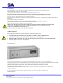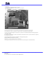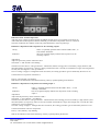
1
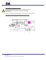
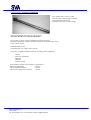
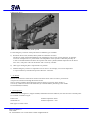
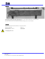
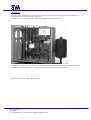
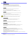
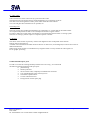
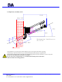
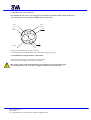
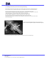
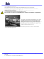
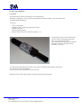
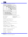
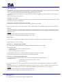
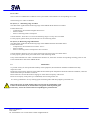
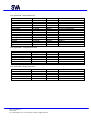
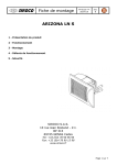
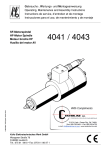
Monitoring system for furnace rooms
Assembly and operating instructions
Table of contents:
1
Safety instructions
2
Application
3
Technical Data
3.1 Generalities
3.2 Ambient temperature
3.3 Water supply
3.4. Compressed Air
3.5 Mounting of the probe
4
Assembly of the monitoring system
5
Recommended spare parts
6
Preparatory assembly works
6.1 Installation of the water connections
6.2 Installation of the air connections
6.3 Installation of the furnace probe camera into the probe housing
7
Mounting of the retraction device
8
Media cabinet ( general description)
8.1 Mounting of the media cabinet
8.2 Set-up of the monitoring device
9
Start up of equipment
9.1Camera
9.2 Setting functions of DIP switches
9.3 Probe
9.4 Retraction device
9.5 Control unit
9.6 Operating instructions GIR 1002/200
9.7 Maintenance work
SVA Industrie-Fernseh GmbH
Marie-Curie Straße 11
40721 Hilden
Tel.: 02103/335500 • Fax.: 02103/ 335501 • E.Mail: [email protected]
All specifications subject to change without notice
1.0 Safety instructions
Prior to connecting and starting the equipment read and understand the safety instructions and operating manuals.
The operating manuals must be kept in a safe place to give the operating personnel access to the
documents at all times.
The manufacturer does not accept any liability for damages caused by improper manipulation and non-observance of the
safety rules.
It is imperative to wear proper safety glasses, face guard and refractory clothes when carrying out any work.
When working on the equipment at the furnace, a further supervising person must be present.
Never deposit the equipment and components belonging to it within a hot area exceeding 60 °C without water flow and air
cooling.
The equipment must also be protected against water penetration and high moisture permeability.
Only qualified service personnel is allowed to open the electrically operated equipment.
Prior to connecting the equipment to the mains, all plugs and cables must be connected.
Do not dismount the plug connections unless electrical power is disconnected.
2.0 Application
First the development of furnace probes permitted a central monitoring
of combustion chambers, burners, melting ends and other objects hard to reach
because of heat and contamination.
Whenever monitoring in a furnace, a boiler or a melting end is required the installation
of a furnace probe is recommended.
The small dimensions of a CCD-colour TV camera module with its special furnace probe lens
permit the installation even in restricted space.
We can offer a variety of special probe types for different installation depths.
Please contact our technicians to discuss the conditions of use
and the material selection of the probe.
SVA Industrie-Fernseh GmbH
Marie-Curie Straße 11
40721 Hilden
Tel.: 02103/335500 • Fax.: 02103/ 335501 • E.Mail: [email protected]
All specifications subject to change without notice
3.0 Technical Data
3.1 General information
-
Power supply:....................230 V
Mains frequency: ........…..50-60 Hz
power consumption: …….max. 500 W
3.2 Ambient temperature
At the probe tip
max. + 2500°C
Outer furnace wall
Camera cable (silicone)
Camera cable (standard)
max. + 80°C close to the retraction device
max. + 250°C
max. + 80°C
3.3 Water supply
The quality of the cooling water can badly influence the life expectancy of the probe house.
Therefore the cooling water should have approximately the quality of drinking water.
In case of polluted water the use of a water re-cooling system or a heat exchanger is required.
This is also recommended for environment protection and cost saving reasons. There is a considerable
reduction of water consumption:
System with heat exchanger
Closed water cooling system
45 %
100%
Due to the low concentration of chlorine ions in mg/l, corrosion damages are much lower.
Admissible contamination of insoluble materials:
Max. 10 mg/l, pH value 6, 0 – 8, 0
Permissible water temperature in the cooling system max. 40°C
after free outflow behind point of consumption.
Delta “T” should not exceeded 3°C.
The water consumption of a probe in a horizontal or downward inclined position is subject to the furnace temperature.
Standard values:
at + 1000 °C
at + 1500 °C
at + 2500 °C
4 l/min.
10l/min.
16l/min
2 bar at the probe
2 bar at the probe
2 bar at the probe
These limit values are not allowed to fall short of at the initial start-up of the system.
They are recalibrated after 24 hours.
See that the water outlet temperature of max. 40 °C is not exceeded.
The water consumption of probes in an upward inclined position is independent of the
furnace temperature, approx. 16 l/min. / 5 bar.
SVA Industrie-Fernseh GmbH
Marie-Curie Straße 11
40721 Hilden
Tel.: 02103/335500 • Fax.: 02103/ 335501 • E.Mail: [email protected]
All specifications subject to change without notice
3.4 Compressed air
Input pressure (outside the compressed-air filter 6 kp/cm 6-bar)
In case of higher input pressure a reducing regulator is required.
For the sealing air and the retractable cylinder surrounding air can be used.
The scavenging air of the camera must be free from oil and water.
Where necessary a cleansing filter must be used.
Sequence of filters: PE 04/20 - SMF 04/20 - AK 04/20
Max. air temperature 38°C at the connection to the probe case.
The proportioning of the sealing air depends on the operating conditions.
If the furnace or the boiler is under high internal pressure, the working pressure of the sealing air must be
increased in order to prevent the flames from penetrating to the outside.
In case of two air circuits in the plant two separate air hoses must be connected
to the media cabinet (see above).
Total air consumption max. 16m3/h , sealing air max.12 m3/h at the initial start-up.
24 hours after commissioning the air consumption will be reduced according to the operating conditions.
3.5 Mounting of the probe
We recommend the installation of an automatic emergency retraction device for safety reasons and to facilitate
maintenance work.
Furnace opening dimensions : probe 60 mm = 80 mm
probe 70 mm = 90 mm
In case of an inclined fitting position of the probe (view upwards) a variation of max. 40 °C on the horizontal line, is
allowed. If this value is exceeded the use of a 70 mm probe is prescribed.
There are no restrictions for probes in horizontal or downward inclined viewing direction.
In case of maintenance work which requires shutting off the water and air flow, the furnace opening must
be sealed by appropriate means in order to prevent the escape of flue gas and flames.
Otherwise personal injuries as well as damages to the lens or the retraction device cannot be excluded.
.
SVA Industrie-Fernseh GmbH
Marie-Curie Straße 11
40721 Hilden
Tel.: 02103/335500 • Fax.: 02103/ 335501 • E.Mail: [email protected]
All specifications subject to change without notice
4.0 Assembly of the monitoring system
In the following chapter you will get by means of the attached Block Diagram
detailed information about the assembly of the system and additional
technical details.
The water re-cooling system will be described in a separate user’s manual. (upon request)
Block Diagram - assembly drawing of the furnace probe - – Numbered (1-17)
1,5 m
15 m
7
5
4
16
6
B- Steuerluft
10mm
A-Steuerluft10mm
Sperrluft 10mm
10mm
Sp³lluft
22mm
Wasser-R³cklauf
22mm
Wasse-Vorlauf
1/2" Luftversorgu
inlet compressed
1/2" Luftversorgu
3/4" Wasser-Vorla
inlet cooling wat
3/4" Wasser -R³ck
return cooling wa
2
II
3
1
Hei▀bereich
hot area
8
13
9
Zentrale
waiting area
10
EIN
AUS
12
17
15
11
15 m
Designinstallation inclmoving device,supply cabinet
for cooling water and compressed ari with control box
SVA Industrie-Fernseh GmbH
Marie-Curie Straße 11
40721 Hilden
Tel.: 02103/335500 • Fax.: 02103/ 335501 • E.Mail: [email protected]
888
14
All specifications subject to change without notice
1.Probe housing ( PATENT Nr.196 50 983)
Four chamber water- and air-cooled
probe housing – different types available with integrated CCD-camera
(optional colour, black or white mode).
Ambient temperature max. 2500 °C at the probe tip.
The probe should not be exposed to the flames.
We can offer a variety of water cooled furnace probes type FRS.
Standard length about 1.000 mm, ambient temperature at the probe tip 2.500 °C,
water- and air-cooled.
Different fields of view:
Axial (Straight) view, angles of 60° and 90°.
The probes are made of different materials according to their application:
-Steel St
-Steel VA (Vanadium)
-Thermax
-Titanium
-Ceramic coated
Probe length according to the customer’s specification:
Maximal probe length
- 4 meters
Dia of standardized probes
- 60 mm
Dia of probes longer than 1500 mm - 70 mm
SVA Industrie-Fernseh GmbH
Marie-Curie Straße 11
40721 Hilden
Tel.: 02103/335500 • Fax.: 02103/ 335501 • E.Mail: [email protected]
All specifications subject to change without notice
2.Retraction device
Retraction device with (transfer) band cylinder
For the emergency retraction of the probe there are different types available:
a)
Retraction device with (transfer) band cylinder for automatic retraction.
The device will be retracted automatically out of the danger zone in case of water shortage, air shortage,
an excess of temperature or a power failure. The temperature of the cylinder is reduced by the help of
a water cooled shield which increases the exposure time of the cylinder (ambient temperature at the device
max. 80°C). The probe orifice in the furnace wall is closes by a shutter.
b) Other types suiting the plant’s requirements are possible.
c)
Manual emergency retraction is required in case of water or air shortage, an excess of temperature
or a power failure by an authorized person within max. 2 minutes.
3. Air Nozzle
The unit is fitted with a 10 mm dia air nozzle at the observation orifice in order to prevent from
overpressure or flame exit through the furnace orifice.
The air volume regulation which depends on the prevailing overpressure in the furnace is
to be set by a ball valve fixed on the media bar (5) so that the flames penetrating to the outside
are neutralised (forced back).
4. Connecting Hoses
The flexible connecting hoses ( length 1700mm) attached between the media bar, the retraction device and the probe
are available in 2 different types:
PTFE-hoses
standard hoses
ambient temperature 200°C
ambient temperature 80°C
Both types are metal coated.
SVA Industrie-Fernseh GmbH
Marie-Curie Straße 11
40721 Hilden
Tel.: 02103/335500 • Fax.: 02103/ 335501 • E.Mail: [email protected]
All specifications subject to change without notice
5.Media bar
The media bar mounted in the region of the probe (approx. 1,5m) is used as a locking device for the permanent
Ermeto piping between media cabinet and media bar.
By means of the ball valves on the media bar, the different feedings can be cut off on demand.
6. Pipework
Piping between media cabinet and media bar is to be done as follows:
Water flow and return
Sealing air and scavenging air
Retraction device
22 mm ¾”
10 mm Ermeto
10 mm Ermeto
Avoid piping in hot areas.
SVA Industrie-Fernseh GmbH
Marie-Curie Straße 11
40721 Hilden
Tel.: 02103/335500 • Fax.: 02103/ 335501 • E.Mail: [email protected]
All specifications subject to change without notice
7.Media cabinet
The testing and switching devices ( water and air) fitting in a compact metal housing protected from splash water
have been developed for a quick failure diagnosis.
A solenoid valve is responsible for the retraction and feeding of the transfer device.
All necessary water flow and air pressure control instruments fit in the compact metal housing protected from dust
and splash water (individual setting) as well as the 2/5 directional control valve of the cylinder.
Diagram of connections media cabinet enclosed.
SVA Industrie-Fernseh GmbH
Marie-Curie Straße 11
40721 Hilden
Tel.: 02103/335500 • Fax.: 02103/ 335501 • E.Mail: [email protected]
All specifications subject to change without notice
8. Camera Cable – Black Box
Housing 150 x 150 x 60 mm, protected from splash water with integrated 30 polar
socket ledge connecting the camera system cable to the high-temperature camera cable.
There is no need for an additional air cooling of the high temperature camera cable.
The housing must be installed outside the hot area, at a distance of approx. 10 m of the camera.
9.Camera Cable
The camera system cable includes a control - and a coaxial video transmission line.
There are two different types of camera system cables:
Silicon cable up to an ambient temperature of 200 °C (camera cable)
System cable up to an ambient temperature of 80 °C (camera cable/system control cable)
10. Switch Box
The switch box fitting in the region of the retraction device permits the local feed and retraction
of the camera probe for maintenance work.
Feeding of the probe is only possible by means of the key switch at the switch box –
For retraction of the probe press the key “retraction device” at the control unit (q.v. point 14).
Attention:
While retracting the probe a safety margin of at least one meter has to be respected.
11. System Control Cable
The 19 mm system control cable can be laid on existing cable brackets in the cold area.
The system cable itself will not be influenced by already laid electric cables.
12. Control Cable
We use a 12 x 0, 5 mm control cable, dia 12 mm, max. temperature 60°C, to transmit all signals
from the switching devices (media cabinet) to the control unit.
13. Air Reserve Tank
The air reserve tank (volume 5 l) is mounted at the media cabinet.
The filling of the tank by means of a non-return valve is supervised by a separate pressure control unit.
In case of an environmental air shortage the stored air volume will be used for the repeated
retraction of the probe.
14. Control Unit
The plug-in panel fitting in a 19” box will be installed in the waiting area.
Continually visual display of the internal temperature of the probe on the front panel (37°C – 47°C)
It is recommended to mount the control unit so that the display of the front panel can always be observed.
Power requirements: 230V/16A
Camera system cable, control – and video cable are connected to the control unit.
Press the key (retraction device) for retraction of the probe.
For feeding of the probe press the entry key on the switch box (q.v. point 10).
This control unit is recommended as a standard device. Also available are units in a splash water protected housing or
in other performances.
SVA Industrie-Fernseh GmbH
Marie-Curie Straße 11
40721 Hilden
Tel.: 02103/335500 • Fax.: 02103/ 335501 • E.Mail: [email protected]
All specifications subject to change without notice
15. Video Cable
Video transmission of the control unit by a protected video cable.
The transmission to the monitor doesn’t need amplification up to a distance of 500 m.
The cable can be laid regardless of other power cables within the cable channel.
Two-wire and glass fibre transmissions are possible, too.
16.Feeding lines
The water supply lines (feeding and discharge) are conducted in ¾” cupper leads to the media cabinet.
At a fireplace temperature of 2500 °C the consumption amounts to approx. 960l/h.
In order to reduce the cooling water consumption we recommend an enclosed water re-cooling system.
The water re-cooling system is subject to a separate operator’s manual.
17. Monitor
The choice of the monitor respectively of the screen diagonal/screen size depends on the distance
between monitor and observer.
Available colour and black and white monitors between 13 and 56 cm (screen diagonal) as well as flat screens of
different dimensions.
While using colour monitors avoid influences by magnetic fields. You may transfer the video signal to a
PC for graphic processing.
5.0 Recommended spare parts
In order to increase the working reliability and the ease of servicing , we recommend
the following testing instruments and spare parts:
• probe housing
• furnace probe lens
• silicon camera cable, completely assembled with connectors
• a set of PTFE high pressure refractory hoses
• CCD-furnace probe camera
• 2 m test cable and test box
• testing monitor with 30 polar plug.
SVA Industrie-Fernseh GmbH
Marie-Curie Straße 11
40721 Hilden
Tel.: 02103/335500 • Fax.: 02103/ 335501 • E.Mail: [email protected]
All specifications subject to change without notice
6.0 Preparatory assembly works
1500
1500
Max 500
Max 500
O/ 60
O/ 60
300
300
100░
100░
O /80
O /80
Max 800
Max 800
25░
25░
Einbauplan Ausfahrvorr
Einbauplan
25.05.95Ausfahrvorr
25.05.95
The installation of a probe system needs sufficient space in the region of the furnace opening.
The drawings of the retraction device give detailed information about the space requirements.
There must be sufficient place on the man-carrying/working platform for the technicians to work on the probe.
In this area the temperature should not exceed 80°C.
In case of an excess of temperature we recommend the mounting of sheet metal heat
deflectors under the working platform.
SVA Industrie-Fernseh GmbH
Marie-Curie Straße 11
40721 Hilden
Tel.: 02103/335500 • Fax.: 02103/ 335501 • E.Mail: [email protected]
All specifications subject to change without notice
6.1 Installation of water connections
The installation of the water–conveying pipes to the media bar should be made outside the hot area.
It is advantageous to lay the pipes in bundles and to isolate them.
Zylinder
Zylinder
Wasser
Wasser
Luft
Isolierung
Luft
The pipes are made of steel, copper or Ermeto.
A cleansing filter should be attached to the water and scavenging air pipes.
6.2 Installation of compressed air connections
The compressed air supply is divided into three branches:
Sealing air, scavenging air and control air (cylinder).
These pipes are laid from the media cabinet to the media bar in a 10 mm Ermeto-pipe.
We recommend to lay the water and air supplies in bundles and to isolate them.
SVA Industrie-Fernseh GmbH
Marie-Curie Straße 11
40721 Hilden
Tel.: 02103/335500 • Fax.: 02103/ 335501 • E.Mail: [email protected]
All specifications subject to change without notice
6.3 Mounting of the furnace probe camera into the probe housing
The mounting of the furnace probe camera on the essential camera carrier insert is realised at the factory.
In case of repair works or cleaning please follow our reassembly instructions: (see attached drawings)
The camera with the probe must be brought into an axial line to the aluminium carrier pipe.
The lock nut has to be adjusted in such a way that the lens tip, centred to the viewing orifice of the probe,
is positioned approx. 2-3 mm backwards (without limitation of the image).
After theses preliminary works the camera carrier can be inserted into the probe.
The camera flange is tightened by 3 hexagon socket head screws (Allen screws).
Now the camera device can be connected to the camera cable or to the control cable.
Starting the unit, the image on the monitor must be aligned in an horizontal level by means of the camera
carrier in the housing.
Unscrew the corrugated thread marked in the picture and turn it
counter clockwise for alignment. Tighten the thread after alignment.
For wiring of the cable form inside the camera carrier please refer to the enclosed drawings.
SVA Industrie-Fernseh GmbH
Marie-Curie Straße 11
40721 Hilden
Tel.: 02103/335500 • Fax.: 02103/ 335501 • E.Mail: [email protected]
All specifications subject to change without notice
7.0 Mounting of the retraction device
The mounting of the retraction device should be carried out in the presence of an SVA technician and
according to his instructions. For space requirements look at the attached dimensional drawings – retraction device.
The unit is designed for an adjustment within a range of +/- 45°.
This is also possible in a horizontal or vertical range of 110 mm. The weight of the retraction device,
including furnace probe, is about 45 kg.
As a result you must ensure the stability of the retraction device support.
Using a retraction device with water cooled mounting plate, the unit must be cooled immediately during installation.
The damping valves attached at the band shielded cylinder must be
adjusted so that while retracting or inserting the probe a sensible
damping of the mechanical movement takes place shortly before
reaching the final position. It must be guaranteed that the movement in
the middle of the cylinder is carried out as quick as possible. The
adjustment, made by turning the knurled screws clockwise or anticlockwise and must be fixed by a lock nut.
The final adjustment of the retraction device must ensure that the probe does not come into contact with the
furnace walls while being inserted.
SVA Industrie-Fernseh GmbH
Marie-Curie Straße 11
40721 Hilden
Tel.: 02103/335500 • Fax.: 02103/ 335501 • E.Mail: [email protected]
All specifications subject to change without notice
8.0 Mounting of the media cabinet
The installation of the media cabinet is made at a distance of about 15 m away from the probe.
Within this area the ambient temperature should not exceed + 50°C.
For pipe dimensions please have a look at the enclosed drawing. For the water and air feeding lines, we recommend the
installation of water and air filters supplied with upstream reducing regulators.
Pay attention in particular to the connection of the water conduits.
8.2. Setting of the monitoring devices
While starting the devices the maximum values have to be set according to the description. Any modifications made
please respect the following specifications.
The air pressure control unit must be adjusted to 2,5 – 3 bar. The contact maker of the water flow control unit
should be set to 800-960 l/h while starting the unit.
Having reached a constant temperature in the probe, the flow can be reduced.
The max. internal probe temperature should not exceed 47 °C. The probe temperature is visualised on the display of the
control unit.
For the air adjustment a distinction between sealing air and scavenging air is to be made:
To neutralize the overpressure in the furnace, the sealing air must be adjusted in order to prevent the flames
from penetrating to the outside.
The scavenge air value is to be set at 2/3 less than the sealing air value.
The scavenging air must be dry and oil free because it will come into direct contact with camera and lens while
cooling the camera housing.
The disregard of these demands will cause an inevitably impurity of the lens.
Furthermore after the first 24 hours after the initial operation of the monitoring device you must pay
attention to:
-
the water flow control
the air flow control
the air pressure control
an excess of temperature
A water circulation free from air must be guaranteed (deairing).
When the limit values have been exceeded or under-run the retraction device must withdraw the probe automatically
out of the hot area.
SVA Industrie-Fernseh GmbH
Marie-Curie Straße 11
40721 Hilden
Tel.: 02103/335500 • Fax.: 02103/ 335501 • E.Mail: [email protected]
All specifications subject to change without notice
9.0 Start-up of equipment
9.1 Camera
The camera has been preset at the factory ( focus and aperture).
If through scavenging air, oil or water have penetrated to the inside of camera or lens the camera must
be purified and focussed again.
Focussing :
-
switch on the camera
transmit the video signal to the monitor (test cable)
install the objective
open the aperture/pinhole
bring into focus an object at a distance of approx. 7 m.
For adjustment, unscrew the lock disk of the
objective and turn the knurled ring for fine
focus. Now tighten the lock disk.
Using a filter this procedure must be repeated
The filter between lens and chip must be
arrested by a lock ring.
For obtaining an optimised picture quality close aperture according to the brightness of the object
(at f 8-16 for pictures in the furnace).
Now the camera can be introduced into the probe case.
Adjustment of the camera dip switches according to the personal requirements.
SVA Industrie-Fernseh GmbH
Marie-Curie Straße 11
40721 Hilden
Tel.: 02103/335500 • Fax.: 02103/ 335501 • E.Mail: [email protected]
All specifications subject to change without notice
9.2 Operator’s Manual for DIP-Switches of furnace probes
On the right side of the camera there are 6 DIP-switches and 2 potentiometers(faders).
block “1” (switch 1 + 2)
block “2” (switch 3 + 4)
block “3” switch 3
block “4” switch 4
White Balance switches
Shutter speed switches
AGC (auto gain control) ON/OFF switch
Y/C/VBS switch
Settings block “1” : WHITE BALANCE switches
switch 1 + switch 2 “OFF” ( switch down) = 3200 K
Setting for indoor shooting under artificial light.
switch 1 “OFF” (switch down) + switch 2 “ON” (switch up) = 5600 K
Daylight setting.
switches 1 + 2 “ON” (switches up)
Manual setting of the colour temperature by means of potentiometer B + R.
Settings block “2” SHUTTER speed switches
switches 3 + 4 “OFF”
= standard operation
switch 3 “OFF”+ switch 4 “ON” = SHUTTER 1/1000
switch 3 “ON” + switch 4 “OFF” = auto-iris
switch 3 „ON“ + switch 4 „ON“
= unconsidered (RGB mode only)
Settings block “3” AGC (auto gain control) ON/OFF switch
Switch 5 “ON” = AGC ON (auto gain control)
Switch 5 “OFF” = permanent intensification 0 dB
Settings block “4” Y/C –VBS switch:
Switch 6 “ON”
Switch 6 “OFF”
= black-white setting
= VBS colour setting
SVA Industrie-Fernseh GmbH
Marie-Curie Straße 11
40721 Hilden
Tel.: 02103/335500 • Fax.: 02103/ 335501 • E.Mail: [email protected]
All specifications subject to change without notice
9.3 The probe
The probe made of VA or Thermax is designed for applications using water or air in hot areas with
a max. temperature of 2500 °C at the probe tip.
The following points should be observed while putting the probe into service:
The probe may only be inserted into the hot area after complete deairation of the water circuit.
Having connected all water hoses and after the first hour of operation the probe should be removed from
the probe holder so that the deairation can be realised as follows:
Hold the probe case alternately with the tip pointing upwards for about 10 sec., and with the tip pointing downwards for
about 10 sec..
Repeat this procedure for several times.
After complete ventilation the water circulation should be checked for air bubbles by means of
the inspection glass (flow control) which is mounted in the media bar.
Perfect circulation without air bubbles must be guaranteed.
While re-inserting the probe into the probe holder, the probe tip should seal with the internal edge of the
furnace wall. According to the lens type it could be advantageous to retract the probe as far as
possible to avoid limitation by the furnace wall.
In any case the probe should not be exposed to the flames!
9.4 Retraction device
Prior to the initial operation of the retraction device respect the following items:
•
•
•
•
The adjustment of forward and return movement is realised by means of damping valves.
Perfect insertion of the probe camera into the furnace wall. – operational test –
Shutting off the air and water flow or in case of deenergizing the probe must be retracted automatically.
That also applies to an excess of temperature.
9.5 Control unit
The control board mounted in a 19” housing, switching element for the control air, water and temperature.
All necessary power units for camera and electronics are integrated in the control unit . The switchboard for control of the
different functions and the display of the internal temperature of the probe fits on the front panel.
Connectors to the camera control system, video socket, alarm output and couplers for the control
cable are installed on the rear panel.
The DIP-switches mounted on the printed boards have been set by the factory according to the requirements
(contacts media bar) .
In case of additional switching contacts the DIP-switches are closed or opened according to their
switching function.
SVA Industrie-Fernseh GmbH
Marie-Curie Straße 11
40721 Hilden
Tel.: 02103/335500 • Fax.: 02103/ 335501 • E.Mail: [email protected]
All specifications subject to change without notice
Control unit:
4x digital input (temperature, water, air, reserve)
4x alarm output ( temperature, water, air, reserve, group signal)
24V =solenoid valve
Operating the retraction device is only possible if a homogeneous switching status is guaranteed.
The potential-free contacts, switched on a 10-polar socket are responsible for the alarm output.
As shown on the attached diagram of connections it is possible to scan detailed information about the group alarm
or the different media.
For control of a solenoid valve or other circuit elements a current feed of 24 Volt (17-polars connector) is required
for interference-free service.
The operating condition of the unit is visualised by LED light-emitting diodes.
During a malfunction the LED will switch off.
Red diode on (constant message) until reset of the device.
The setting of the temperature limit values is prescribed in the enclosed operator’s manual (GIR 1002).
SVA Industrie-Fernseh GmbH
Marie-Curie Straße 11
40721 Hilden
Tel.: 02103/335500 • Fax.: 02103/ 335501 • E.Mail: [email protected]
All specifications subject to change without notice
9.6
Operating Manual GIR 1002/200
Indication of the Actual Temperature
After the supply voltage has been applied, the GIR200 PT100 carries out a segment test for about 8s.
Afterwards, the actual temperature will be indicated, provided that a temperature sensor is connected.
The LED 1 indicates the condition of the relay (LED illuminates: relay has picked up).
Indication / adjustment of the on-position of the switching output 1
Call by:
Indication:
button 1; repeatedly push the button until the LED's "SET“, "1“
and "ON/SP“ illuminate.
The seven-segment display indicates the on-position of the
switching output 1.
Adjustment:
Adjust on-position by means of button 2 and 3.
The LED's "1“ and "ON/SP“ start flashing.
The buttons 2 and 3 have a "roll-type function“. That means, that the closing point is increased by 1 digit (button 2) and
decreased (button 3) respectively, when it is shortly actuated (less than 1 second). If actuated for a longer time (longer than 1
second), the value begins to "roll" up and down.
Once a "rolling" of approx. 150 digits has been carried out, the "rolling procedure" gets accelerated by the factor of 10.
Confirm the new on-position with button 4.
LED "1“ and "ON/SP“ stop flashing.
Shift back to the indication of the actual measuring value by repeated pushing of the button 4.
Indication / adjustment of off-position of switching output 1
Call by:
Indication:
button 1, repeatedly push the button until the LED's "SET“, "1“ and
"OFF/Hy.“ illuminate.
The seven-segment display indicates the off-position of the switching
output 1.
Adjustment:
Adjust the off-position by means of button 2 and 3.
The LED's „1“ and „OFF/Hy.“ start flashing.
The buttons 2 and 3 have a "roll-type function“. That means that the switching point is increased by 1 digit (button 2) and
decreased (button 3) respectively when it is shortly actuated. If actuated for a longer time (longer than 1 second) the value
will begin to "roll" up and down.
Once the "rolling" of approx. 150 digits has been carried out, the "rolling procedure" gets accelerated by the factor of 10.
Confirm with button 4 the new off-position.
LED „1“ and „OFF/Hy.” stop flashing.
Shift to the indication of the actual measuring value by repeated pushing the button 4.
SVA Industrie-Fernseh GmbH
Marie-Curie Straße 11
40721 Hilden
Tel.: 02103/335500 • Fax.: 02103/ 335501 • E.Mail: [email protected]
All specifications subject to change without notice
Offset Adjustment:
The GIR200 Pt 100 is factory-calibrated onto Pt100 sensor according to DIN43760 etc. Thus, the control unit is immediately
usable as soon as the temperature sensor and the supply voltage have been connected.
It is possible that in certain applications an offset adjustment becomes necessary.
(e. g. for the compensation of influences by cable resistances caused by the application of two-conductor or three-conductor
connection.)
In this case please proceed as follows:
Push button 1 (front side).
Additionally push (approx. 1 s) mini push button on rear side of the GIR 1002 Pt100 (behind the terminal for the sensor) until
the LED“CAL“ (front side) illuminates.
LED's "Scale“, "OFF/Hy.“ and LED “CAL” illuminate.
The display shows the offset value memorized in the GIR 1002 Pt100 (zero offset).
Set the new offset value by means of the buttons 2 and 3 (LED "OFF/Hy.“ starts flashing). Afterwards confirm with button
4.
Example:
If at a temperature of 0.0 °C the GIR 1002 Pt100 indicates a temperature of 0.3 °C due to a longer connection cable (only in
case of two-conductor and three-conductor connection), then the GIR 1002 Pt100 can be aligned to 0.0°C by the input of an
offset value of 0.3.
Caution:
This value setting influences the indication of the GIR 1002 Pt100.
Due to this reason, the offset value should normally be set at 0.0.
Error codes
The occurrence of inadmissible conditions in the system leads to the indication of corresponding error codes.
The following error codes are defined:
FE (Error) 1: Measuring range exceeded
This fault message signals that the measuring range of the GIR 200 Pt100 has been exceeded.
Possible fault cause:
- Temperature to be measured is higher than 199.9°C.
- Sensor is defect.
- Sensor connecting cable is interrupted.
Counter-measure: Reset FE 1 as soon as the measuring range is not any more exceeded.
For this purpose, please check your PT100 sensor or the connecting cables.
FE (Error) 2: Measuring range fallen below
This fault message signals that the measuring range of the GIR200 Pt100 has been fallen below.
Possible fault cause:
- Temperature to be measured is less than –50.0°C.
- Sensor is defect.
Set the new offset value by means of the buttons 2 and 3 (LED "OFF/Hy.“ starts flashing) and confirm then with button 4.
Example:
If at a temperature of 0.0 °C the GIR 1002 Pt100 indicates a temperature of 0.3 °C due to a longer connection cable (only in
case of two-wire and three-wire connection), then the GIR 1002 Pt100 can be aligned to 0.0°C by setting 0.3.
Caution:
This value setting influences the indication of the GIR 1002 Pt100.
Due to this reason, the offset value should normally be set at 0.0.
SVA Industrie-Fernseh GmbH
Marie-Curie Straße 11
40721 Hilden
Tel.: 02103/335500 • Fax.: 02103/ 335501 • E.Mail: [email protected]
All specifications subject to change without notice
Error codes
The occurrence of inadmissible conditions in the system leads to the indication of corresponding error codes.
The following error codes are defined:
FE (Error) 1: Measuring range exceeded
This fault alarm signals that the measuring range of the GIR 200 Pt100 has been exceeded.
Possible fault cause:
- Temperature to be measured is higher than 199.9°C
- Sensor is defect.
- Sensor connecting cable is interrupted.
Counter-measure: Reset FE 1 as soon as the measuring range is not any more exceeded.
For this purpose, please check your PT100 sensor or the connecting cables.
FE (Error) 2: Measuring range fallen below
This fault alarm signals that the measuring range of the GIR200 Pt100 has been fallen below.
Possible fault cause:
- Temperature to be measured is lower than –50.0°C
- Sensor is defect
- Sensor connecting cable is interrupted or short-circuited.
Counter-measure: Reset FE 2 as soon as the measuring range will not any more fallen below.
For this purpose, please check your Pt100 sensor or the connecting cables.
If any of the indicated error codes or malfunctions should occur, check first of all the corresponding switching points as well
as the entered offset value of the GIR200 Pt100.
9.7
Maintenance
To provide security for the operational reliability of the equipment, the maintenance should be included in the daily
inspection round.
During this inspection the functions in the media cabinet and the probe temperature should be checked. In addition, a function
check of the telescope should be carried out.
Please make also sure that the used scavenging air of the camera is kept dry and oil-free.
However an impurity of the probe tip is established, clean it with greatest care.
It is strictly prohibited to use any cleaning agents with biting effect and sharp-edged or pointed devices.
Retract the probe out of the furnace when carrying out any maintenance work.
It must be ensured that by no means flames can get out of the inspection glass.
If necessary, it must be enclosed with corresponding fire-proof material.
SVA Industrie-Fernseh GmbH
Marie-Curie Straße 11
40721 Hilden
Tel.: 02103/335500 • Fax.: 02103/ 335501 • E.Mail: [email protected]
All specifications subject to change without notice
List of materials - media cabinet SVA
Designation
water flow meter
air flow meter
pressure control device air
control valve 2/5
switch cabinet
air reservoir
Hensel box with terminals
back pressure valve
screwing
screwing
screwing
screwing
Stop valve ½“
Stop valve
Type
RVD,MS
SN480-A2-GR
901.41WE
S9 581
LA.M1060
5L
9100
RHD
SV10PL
SV22PL
EGE22-LR-ED
EVW10-PL
DN 15,ENIL 1201
DV 10-PL
Order no.
FRM251
FRM260
FRM259
FRM261
FRZ419
FRM262
FRM255
FRM263
FRM266
FRM265
FRM267
FRM268
FRM253
FRM252
Technical data
2,0-16L/min. contact 1,5A ½“
G1/2“,24Vrelaise0-25sec.S. short
EW1,5+0,15/1,3+0,15BAR
RF.1,4“
dimensions 600x600x200
5.1 console
Modular terminals 9700AGS35
ERMETO
ERMETO
ERMETO
ERMETO
ERMETO
Water
air
List of materials - retraction device SVA
Main cylinder
king post
back pressure control valve
fastening cylinder
high speed locking device
shield
safety valve
housing
OSP-P32-00100.32D
E1-large
DRV
DZS30225
D60mm
D60mm
2 bar
D60mm
FRA204
FRA205
FRA202
FRA203
FRA210
FRA211
FRA209
FRA206
stroke 800-Viton
for OSP32
¼“
with mounting plate
water-cooled
½“
Thermax with furnace opening cap
FRG100
FRK151
TVO571
FRS364
FRZ405
FRZ406
½“ water, 10mm air, Thermax tip
½“ 12V PAL
4mm ½“ filter 16 x
19“ case
Connection water air cylinder
7 pieces 3x15mm,4x10mm
List of materials- furnace probe SVA
Probe housing
CCD colour camera
lens 4mm straight view
Control unit
Media bar
hoses
D60mm 1m long.
XC999P (XC555)
Probe lens
STG95 STD
6 Ventilen
PTFE
SVA Industrie-Fernseh GmbH
Marie-Curie Straße 11
40721 Hilden
Tel.: 02103/335500 • Fax.: 02103/ 335501 • E.Mail: [email protected]
All specifications subject to change without notice