1
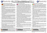
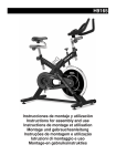
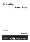
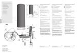
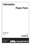
Information
Power Parts
61112035044
09. 2007
3.211.235
*3211235*
www.ktm.com
DEUTSCH
Danke, dass Sie sich für KTM Power Parts entschlossen haben.
Alle unsere Produkte wurden nach den höchsten Standards entwickelt und gefertigt, unter Verwendung der besten verfügbaren
Materialien.
KTM Power Parts sind rennerprobt und gewährleisten ultimative Performance.
KTM KANN NICHT VERANTWORTLICH GEMACHT WERDEN FÜR FALSCHE MONTAGE ODER VERWENDUNG DIESES PRODUKTS. Bitte
befolgen Sie die Montageanleitung. Wenn bei der Montage Unklarheiten auftreten, wenden Sie sich bitte an eine KTM Fachwerkstätte.
Danke.
ENGLISH
2
Thank you for choosing KTM Power Parts!
All of our products are designed and built to the highest standards using the finest materials available.
KTM Power Parts are race proven to offer the ultimate in performance.
KTM WILL NOT BE HELD LIABLE FOR IMPROPER INSTALLATION OR USE OF THIS PRODUCT. Please follow all instructions provided. If you
are unsure of any installation procedure, please contact a certified KTM dealer.
Thank you.
ITALIANO
2
Grazie per aver deciso di acquistare un prodotto KTM Power Parts.
Tutti i nostri prodotti sono stati sviluppati e realizzati secondo i massimi standard e con l'impiego dei migliori materiali disponibili.
Le KTM Power Parts sono collaudate nelle competizioni ed assicurano altissime prestazioni.
KTM NON PUÒ ESSERE RESA RESPONSABILE PER UN MONTAGGIO O USO IMPROPRIO DI QUESTO PRODOTTO. Per favore osservate le
istruzioni nel manuale d'uso.Se dovessero sorgere dei dubbi al montaggio, rivolgetevi ad un'officina specializzata KTM.
Grazie.
FRANCAIS
2
Nous vous remercions d'avoir choisi KTM Power Parts.
Tous nos produits ont été développés et réalisés selon les plus hauts standards et en utilisant les meilleurs matériaux disponibles.
Les Power Parts de KTM ont fait leurs preuves en compétition et garantissent les meilleures performances.
LA RESPONSABILITÉ DE KTM NE SAURAIT ÊTRE ENGAGÉE EN CAS D'ERREUR DANS LE MONTAGE OU L'UTILISATION DE CE PRODUIT.
Il convient de respecter les instructions de montage.
Si quelque chose n'est pas clair lors du montage, il faut s'adresser à un agent KTM.
Merci.
ESPANOL
2
2
Gracias por haberse decidido por el Power Parts KTM.
Todos nuestros productos han sido desarrollados y producidos según los estándares más altos utilizando los mejores materiales
disponibles.
Las KTM Power Parts están probadas en competencia y garantizan un óptimo rendimiento.
NO SE PUEDE HACER RESPONSABLE A LA KTM POR UN MONTAJE O UN USO INCORRECTO DE ESTE PRODUCTO.
Le rogamos seguir las instrucciones para el montaje.
Si durante el montaje resultan confusiones le rogamos contactar a un taller especializado KTM.
Gracias.
Alarmanlage Befestigungskit 611.12.035.044
1x
4x
4x
1x
1x
4x
1x
Halteblech
ISO Blindmutter M8x12,7
Zylinderschraube M4x22 DIN 84A-4.8
EJOT PT Schraube K60x20Z
REED Schalter
Linsenkopfschraube DIN 7981 3,5x16
Anbauanleitung
611.12.035.050
611.12.035.060
0084040223
0017060203
600.12.035.180
0981350163
DEUTSCH
Lieferumfang
3
Montage
Sitzbank abnehmen und Bordwerkzeug aus dem Staufach entfernen.
Die vier ISO-Blindmuttern (1) in das Halteblech einführen. Halteblech mit
der Lasche in die hintere Ausnehmung des Staufaches (2) einführen.
Darauf achten, dass der Haltegummi für das Werkzeug unter dem Blech
geführt wird. Halteblech mit der mitgelieferten EJOT PT Schraube (3)
im Staufach verschrauben.
2
1
3
Blindstecker des Alarmanlagenkabelstrangs (4) abziehen, und Alarmanlagenkabelstrang mit der Alarmanlage verbinden. Schutztülle des
Kabelstranges über die Alarmanlage ziehen und Kabelverlegung auf
Knickfreiheit und Scheuerstellen prüfen.
4
Alarmanlage mit den vier Zylinderschrauben M4x22 auf dem Halter verschrauben.
DEUTSCH
Super Duke
REED Schalter (1) mittig und bündig zur Vorderkante des Staufaches positionieren und die beiden Löcher körnen. Anschließend mit einem 2mm
Bohrer die Löcher bohren. REED Schalter mit den Linsenkopfschrauben
M3,5x16 verschrauben.
Super Duke R
1
1
4
Super Duke
Super Duke R
2
2
REED Schalter (2) wie im Bild gezeigt am Sitzbankboden positionieren und
vorerst nur mit doppelseitigem Klebeband befestigen. Anschließend den
Funktionstest (am Ende der Anbauanleitung beschrieben) durchführen.
Sollte der REED Schalter beim Abnehmen der Sitzbank den Alarm nicht
auslösen, so ist die Position näher an das Gegenstück, welches im
Staufach montiert ist, zu legen. Der maximale Abstand der beiden REED
Magnete sollte 10 mm nicht überschreiten. Ist die richtige Position des
REED Schalters gefunden, die beiden Löcher körnen. Anschließend mit
einem 2 mm Bohrer vorsichtig durch den Sitzbankboden bohren; keinesfalls
zu tief bohren, da sonst der Sitzbankbezug beschädigt werden kann. REED
Schalter mit den Linsenkopfschrauben M3,5x16 verschrauben.
Bordwerkzeug mit Haltegummi im Staufach sichern und Sitzbank montieren.
Funktionstest
Bedienungsanleitung der Alarmanlage 600.12.035.100 aufmerksam
durchlesen und anschließend einen Funktionstest durchführen. Auch
die Funktion des REED Schalters üperprüfen. Dazu Alarmanlage
aktivieren und Sitzbank abnehmen.
Handsender der Alarmanlage bereithalten, um sie jederzeit
ausschalten zu können, da der Schallpegel der Alarmsirene 114 dBA
beträgt.
Scope of supply
Alarm system mounting kit 611.12.035.044
1x
4x
4x
1x
1x
4x
1x
Retaining bracket
ISO M8x12,7 cap nut
M4x22 cylinder screw, DIN 84A-4.8
EJOT PT screw K60x20Z
REED switch
3.5x16 oval head screw, DIN 7981 3,5x16
Mounting instructions
611.12.035.050
611.12.035.060
0084040223
0017060203
600.12.035.180
0981350163
Remove the seat and take the tool set out of the storage compartment.
ENGLISH
Mounting
5
Insert the four ISO cap nuts (1) in the retaining bracket. Insert the tab on
the retaining bracket in the recess at the back of the storage compartment (2). Make sure to run the rubber strap for the tools under the bracket. Screw the retaining bracket onto the storage compartment with the
EJOT PT screw (3) included in the scope of supply.
2
1
3
Pull off the dummy plug on the alarm system wiring harness (4) and
connect the alarm system wiring harness to the alarm system. Pull the
grommet on the wiring harness over the alarm system and make sure
the cables are free of kinks and scuff marks.
4
Screw the alarm system onto the holder using the four M4x22 cylinder
screws.
Super Duke
Position the REED switch (1) centered and flush with the front edge of the
storage compartment and punch the two holes. Use a 2mm bit to drill
the holes. Screw on the REED switch with the M3.5x16 oval head screws.
Super Duke R
1
ENGLISH
Super Duke
1
Super Duke R
2
2
Position the REED switch (2) on the bottom of the seat as illustrated.
Temporarily fasten with double-sided tape. Perform the functional check
(described at the end of the mounting instructions). If the REED switch
does not trigger the alarm when the seat is removed, position it closer to
the other magnet mounted in the storage compartment. The maximum
distance between the two REED magnets should not exceed 10 mm. When
the REED switch is correctly positioned, punch the two holes. Then use
a 2mm bit and carefully drill through the bottom of the seat; do not drill
down too low or you will damage the seat cover. Screw on the REED switch
using the M3.5x16 oval head screws.
6
Hold the tool set in place with the rubber strap and mount the seat.
Functional check
Carefully read through the alarm system operating instructions
600.12.035.100 and perform a functional check. Also make sure the
REED switch works correctly (activate the alarm system and remove
the seat).
Keep the handheld transmitter for the alarm system handy to be able
to turn it off quickly since the siren has a sound level of 114 dBA.
Volume della fornitura
Kit di fissaggio allarme antifurto 611.12.035.044
N.
N.
N.
N.
N.
N.
N.
1
4
4
1
1
4
1
piastra di supporto
dadi ciechi M8x12,7
viti TC M4x22 DIN 84A-4.8
vite EJOT PT K60x20Z
coppia di contatti reed
viti a testa bombata DIN 7981 3,5x16
istruzioni di montaggio
611.12.035.050
611.12.035.060
0084040223
0017060203
600.12.035.180
0981350163
Montaggio
Inserire i quattro dadi ciechi ISO (1) nella piastra di supporto. Inserire la
linguetta della piastra di supporto nella fessura posteriore del vano portaoggetti (2). Far attenzione che l'elastico di fissaggio per la borsa attrezzi
passi sotto la piastra. Avvitare la piastra di supporto con la vite EJOT PT
(3) nel vano portaoggetti.
2
1
3
ITALIANO
Smontare la sella e togliere la borsa attrezzi dal vano portaoggetti.
7
Togliere il connettore cieco del cablaggio della centralina d'allarme (4) e
collegare il cablaggio alla centralina d'allarme. Infilare il cappuccio di
protezione del cablaggio sulla centralina e controllare che i cavi non
presentino pieghe o punti di sfregamento.
4
Avvitare la centralina d'allarme con le quattro viti TC M4x22 sulla piastra di
supporto.
Super Duke
Posizionare il contatto reed (1) centralmente ed a filo con il bordo anteriore
del vano portaoggetti e bulinare i due punti di foratura. Praticare quindi
i due fori con una punta da 2 mm. Avvitare il contatto reed con le viti a
testa bombata M3,5x16.
Super Duke R
1
Super Duke
1
Super Duke R
2
2
Posizionare l'altro contatto reed (2) come illustrato sul fondo sella e per ora
fissarlo solo con un nastro biadesivo. Eseguire quindi il test funzionale
(descritto alla fine delle presenti istruzioni di montaggio). Se i contatti
reed non dovessero far scattare l'allarme alla rimozione della sella, avvicinare la posizione del contatto reed sul fondo sella a quella del contatto
montato nel vano portaoggetti. La distanza massima tra i due magneti
reed non dovrebbe superare i 10 mm. Una volta trovata la posizione giusta
del contatto reed, bulinare i due punti di foratura. Poi forare con cautela
il fondo sella con una punta da 2 mm; in nessun caso praticare dei fori
troppo profondi per non danneggiare la fodera della sella. Avvitare il contatto reed con le viti a testa bombata M3,5x16.
ITALIANO
Legare la borsa attrezzi con l'elastico di fissaggio nel vano portaoggetti e rimontare la sella.
8
Test funzionale
Leggere attentamente il manuale d'uso dell'allarme antifurto
601.12.035.100 ed eseguire una prova di funzionamento. Controllare
anche il funzionamento dei contatti reed. A questo scopo attivare
l'allarme antifurto e togliere la sella.
Tener pronto il telecomando dell'antifurto per poter spegnerlo in
qualsiasi momento, perché la potenza acustica della sirena d'allarme è
di 114 dBA.
Kit de livraison
Kit de fixation alarme 611.12.035.044
1
4
4
1
1
4
1
support
écrous prisonniers M8x12,7
vis à tête cylindrique M4x22 DIN 84A-4.8
vis EJOT PT K60x20Z
contacteur REED
vis à tête bombée DIN 7981 3,5x160
notice de montage
611.12.035.050
611.12.035.060
0084040223
0017060203
600.12.035.180
981350163
Montage
Déposer la selle et sortir l'outillage se trouvant dans la boîte.
Enfiler dans le support les 4 écrous prisonniers ISO (1). Enfiler le support
dans la boîte en faisant prendre la languette dans la fente à l'arrière de
la boîte (2). Faire attention à ce que le caoutchouc qui tient les outils
passe sous le support. Fixer le support dans la boîte au moyen de la vis
EJOT PT fournie (3).
2
1
Retirer la prise borgne en bout du faisceau pour l'alarme (4) et relier le
faisceau à l'alarme. Faire glisser le capuchon de protection sur le
raccordement et vérifier que les fils n'accrochent nulle part et ne
frottent pas.
4
FRANCAIS
3
9
Fixer l'alarme sur le support au moyen des quatre vis à tête cylindrique M4x22.
Super Duke
Présenter le contacteur REED (1) de manière à ce qu'il soit exactement au
milieu du bord avant de la boîte et qu'il affleure ce bord. Pointer les deux
trous puis les percer avec un foret de 2 mm. Fixer le contacteur au moyen
des vis à tête bombée M3,5x16.
Super Duke R
1
Super Duke
1
Super Duke R
2
2
Présenter le contacteur REED (2) sur la selle comme cela est indiqué sur
l'illustration et le fixer dans un premier temps avec du double face seulement. Effectuer le test de fonctionnement tel que décrit à la fin de cette
notice. Si le contacteur REED ne devait pas déclencher l'alarme quand
on retire la selle, il faudrait corriger sa position pour le rapprocher de
l'autre partie fixée sur la boîte. L'écart maximum entre les deux aimants
REED ne doit pas excéder 10 mm. Quand on a trouvé la bonne position
pour le contacteur, on pointe les deux trous, puis on perce avec précaution le fond de la selle en utilisant un foret de 2 mm. Faire attention à
ne pas aller trop loin pour ne pas abîmer le dessus de la selle. Fixer le
contacteur au moyen des vis à tête bombée M3,5x16.
Remettre les outils dans la boîte et les fixer avec le caoutchouc. Remonter
la selle.
FRANCAIS
10
Test de fonctionnement
Lire attentivement la notice d'utilisation de l'alarme 600.12.035.100
avant d'effectuer le test. Vérifier également le bon fonctionnement du
contacteur REED. Pour cela, activer l'alarme et retirer la selle.
Tenir la télécommande de l'alarme sous la main pour pouvoir couper
aussitôt. En effet, le niveau sonore de l'alarme se situe à 114 dBA.
Volumen de suministro
Dispositivo de alarma juego de fijación 611.12.035.044
1
4
4
1
1
4
1
chapa de soporte
tuercas ciegasISO M8x12,7
tornillos cilíndricos M4x22 DIN 84A-4.8
tornillo EJOT PT K60x20Z
interruptor REED
tornillos de cabeza alomada DIN 7981 3,5x16
Instrucciones de montaje
611.12.035.050
611.12.035.060
0084040223
0017060203
600.12.035.180
0981350163
Montaje
Quitar el banco de asiento y retirar la herramienta de a bordo del compartimiento auxiliar.
Introducir las cuatro tuercas ciegas (1) en la chapa de soporte. Introducir la
chapa de soporte con el cubrejunta en el escote trasero del compartimiento auxiliar (2). Tener cuidado de que el elástico de soporte para la
herramienta sea conducido por debajo de la chapa. Atornillar la chapa
de soporte con el tornillo EJOT PT (3) suministrado en el compartimiento
auxiliar.
2
1
3
Retirar la clavija inactiva del tramo de cables del dispositivo de alarma (4)
y conectar el tramo de cables del dispositivo de alarma con el
dispositivo de alarma. Sacar la boquilla de protección del tramo de
cables por encima del dispositivo de alarma y examinar que el tendido
de cables esté libre de dobladuras y puntos de fricción.
Atornillar el dispositivo de alarma sobre el soporte con los cuatro tornillos
cilíndricos M4x22.
ESPANOL
4
11
Super Duke
Posicionar el interruptor REED (1) en el centro y a ras con el borde delantero del compartimiento auxiliar y punzonar los dos agujeros. Enseguida
perforar los agujeros con un taladro de 2 mm. Atornillar el interruptor
REED con los tornillos de cabeza alomada M3,5x16.
Super Duke R
1
Super Duke
1
Super Duke R
2
2
Posicionar el interruptor REED (2) en el fondo del banco de asiento tal y
como está indicado en la fotografía y fijarlo primero solamente con una
cinta adhesiva de doble cara. Seguidamente efectuar la prueba de funcionamiento (descrita al final de las instrucciones de montaje). En caso
que el interruptor REED no accione la alarma cuando se quita el banco
de asiento, entonces hay que poner la posición más cerca a la contrapieza montada en el compartimiento auxiliar. La distancia máxima entre
ambos imanes REED no debería exceder los 10 mm. Cuando se haya encontrado la posición correcta del interruptor REED, punzonar ambos agujeros. Enseguida perforar cuidadosamente con un taladro de 2 mm a través del fondo del banco de asiento; de ninguna manera taladrar demasiado
profundo, de lo contrario se puede dañar el revestimiento del banco de
asiento. Atornillar el interruptor REED con el tornillo de cabeza alomada
M3,5x16.
Asegurar la herramienta de a bordo en el compartimiento auxiliar con el elástico de soporte y montar el banco de asiento.
Prueba de funcionamiento
Leer atentamente el manual de instrucciones del dispositivo de alarma
600.12.035.100 y seguidamente efectuar una prueba de
funcionamiento. Examinar también el funcionamiento del interruptor
REED. Para ello activar el dispositivo de alarma y quitar el banco de
asiento.
Tener listo el emisor manual del dispositivo de alarma para poder
desconectarlo en todo momento, ya que el nivel sonoro de la sirena de
alarma es de 114 dBA.
ESPANOL
12