1
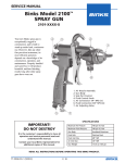
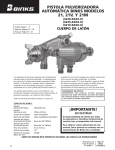
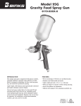
Binks Model 2100 Spray Gun 2100-XXXX-X Your new Binks spray gun is exceptionally rugged in construction, and is built to stand up under hard, continuous use. However, like any other fine precision instrument, its most efficient operation depends on a knowledge of its construction, operation, and maintenance. Properly handled and cared for, it will produce beautiful, uniform finishing results long after other spray guns have worn out. 2 1 3 4 Types of Installation SIPHON FEED CUP HOOKUP Air pressure for atomization is regulated at extractor. The amount of fluid is adjusted by fluid control screw on gun, viscosity of paint, and air pressure (see figure 1). 6 Separator Air Siphon Cup Figure 1 PRESSURE FEED CUP HOOKUP For fine finishing with limited spraying. Air pressure for atomization is regulated at extractor; fluid pressure at cup regulator. For heavy fluids and internal mix nozzle spraying, fluid adjusted by control screw on gun. 1. 2. 3. 4. 5. 6. 7. Air Nozzle Assembly Gun Body Side Port Control Fluid Control Knob Air Connection 1/4" NPS (m) Fluid Connection 3/8" NPS (m) Air Adjusting Valve Pressure cup also available less regulator (see figure 2). Separator Cup Regulator Air Fluid Pressure Cup Figure 2 PRESSURE FEED TANK HOOKUP PRESSURE FEED CIRCULATING HOOKUP For portable painting operations (double regulator). For heavy production spraying. Air pressure for atomization and fluid supply is regulated by two individual air regulators on tank (see figure 4). Air pressure atomization regulated at extractor. Fluid pressure regulated at fluid regulator (see figure 5). PRESSURE FEED TANK HOOKUP For medium production spraying (single regulator). Air pressure for atomization is regulated at extractor, fluid pressure at tank regulator (see figure 3). Separator Air Outlet Air Inlet Pressure Tank Figure 3 5 7 Separator Air Supply Fluid Regulator Air Supply Pressure Tank Figure 4 Air Fluid Fluid Figure 5 Fluid Outlet Air Fluid Replaces Part Sheet 77-2895R-2 Part Sheet 77-2895R-3 In this part sheet, the words WARNING, CAUTION and NOTE are used to emphasize important safety information as follows: ! WARNING Hazards or unsafe practices which could result in severe personal injury, death or substantial property damage. ! Caution Hazards or unsafe practices which could result in minor personal injury, product or property damage. ! NOTE Important installation, operation or maintenance information. Warning Read the following warnings before using this equipment. Read the Manual Before operating finishing equipment, read and understand all safety, operation and maintenance information provided in the operation manual. Inspect the Equipment Daily Inspect the equipment for worn or broken parts on a daily basis. Do not operate the equipment if you are uncertain about its condition. Wear Safety Glasses Failure to wear safety glasses with side shields could result in serious eye injury or blindness. Never Modify the Equipment Do not modify the equipment unless the manufacturer provides written approval. De-energize, Disconnect and Lock Out All Power Sources During Maintenance Failure to De-energize, disconnect and lock out all power supplies before performing equipment maintenance could cause serious injury or death. Know Where and How to Shut Off the Equipment in Case of an Emergency Operator Training All personnel must be trained before operating finishing equipment. Pressure Relief Procedure Always follow the pressure relief procedure in the equipment instruction manual. Equipment Misuse Hazard Equipment misuse can cause the equipment to rupture, malfunction, or start unexpectedly and result in serious injury. Noise Hazard You may be injured by loud noise. Hearing protection may be required when using this equipment. Keep Equipment Guards in Place Do not operate the equipment if the safety devices have been removed. Static Charge Fluid may develop a static charge that must be dissipated through proper grounding of the equipment, objects to be sprayed and all other electrically conductive objects in the dispensing area. Improper grounding or sparks can cause a hazardous condition and result in fire, explosion or electric shock and other serious injury. Projectile Hazard You may be injured by venting liquids or gases that are released under pressure, or flying debris. FIRE AND EXPLOSION HAZARD Never use 1,1,1-trichloroethane, methylene chloride, other halogenated hydrocarbon solvents or fluids containing such solvents in equipment with aluminum wetted parts. Such use could result in a serious chemical reaction, with the possibility of explosion. Consult your fluid suppliers to ensure that the fluids being used are compatible with aluminum parts. Pinch Point Hazard Moving parts can crush and cut. Pinch points are basically any areas where there are moving parts. Automatic Equipment Automatic equipment may start suddenly without warning. CA PROP 65 PROP 65 WARNING WARNING: This product contains chemicals known to the State of California to cause cancer and birth defects or other reproductive harm. FOR FURTHER SAFETY INFORMATION REGARDING BINKS AND DEVILBISS EQUIPMENT, SEE THE GENERAL EQUIPMENT SAFETY BOOKLET (77-5300). 2 AIR PRESSURE Atomizing pressure must be set properly to allow for the drop in air pressure between the regulator and the spray gun. Only 34 PSI at gun inlet 25 feet of 1/4” I.D. hose causes a drop of 26 PSI between the air supply and the gun. (NOT RECOMMENDED) With 60 psi applied at air supply 5/16” 1/4” 48 PSI at gun inlet Cross section view showing comparison of inside hose diameters (actual size). 60 lbs. regulated pressure 25 feet of 5/16” I.D. hose causes a drop of 12 PSI between the air supply and the gun. For this reason Binks recommends the use of 5/16” hose. (RECOMMENDED) DEVILBISS oil and water SEPARATOR is important Achieving a fine spray finish without the use of a good oil and water extractor is virtually impossible. A DeVilbiss regulator / separator serves a double purpose. It eliminates blistering and spotting by keeping air free of oil and water, and it gives precise air pressure control at the gun. Binks recommends using Model HFRL-508 Oil and Water Separator / Regulator. See your local distributor for other models. GUN HANDLING The first requirement for a good resultant finish is the proper handling of the gun. The gun should be held perpendicular to the surface being covered and moved parallel with it. The stroke should be started before the trigger is pulled and the trigger should be released before the stroke is ended. This gives accurate control of the gun and material. The distance between gun and surface should be 6 to 12 inches depending on material and atomizing pressure. The material deposited should always be even and wet. Lap each stroke over the preceding stroke to obtain a uniform finish. Coating will be light at this point Coating will be heavy at this point 6 to 12 inches TRAVEL of GUN Start stroke Wrong Coating should be even and wet when spraying Pull trigger Release trigger End of stroke Right NOTE To reduce overspray and obtain maximum efficiency, always spray with the lowest possible atomizing air pressure. AIR SUPPLY It is extremely poor practice to mount the oil and water extractor on or even near the compressor unit. The temperature of the air is greatly increased as it passes through the compressor and this compressed air must be cooled before the moisture in it will condense. If the air from the compressor is still warm when it passes through the oil and water extractor, moisture will not be effectively removed, but will remain in suspension. Then, when the air cools in the hose beyond the extractor, the moisture will condense into drops of water and cause trouble. Air lines must be properly drained Pitch all air lines back towards the compressor so that condensed moisture will flow back into the air receiver where it can be removed by opening a drain. Every low point on an air line acts as a water trap. Such points should be fitted with an easily accessible drain. See diagram. 3 The spray pattern of the Binks gun is variable from round to flat with all patterns in between. Spray width adjustment Fluid control screw Spray width adjustment: Turn clockwise for round, counterclockwise for fan. Fluid control screw: Turn clockwise to decrease flow, counterclockwise to increase flow. As width of spray is increased, more material must be allowed to pass through the gun to obtain the same coverage on the increased area. In normal operation, the wings on the nozzle are horizontal as illustrated here. This provides a vertical fan shaped pattern which gives maximum coverage as the gun is moved back and forth parallel to the surface being finished. SIPHON SPRAYING PRESSURE SPRAYING Set atomization pressure at approximately 50 PSI for lacquer and 60 PSI for enamel. Test spray. If the spray is too fine, reduce the air pressure or open fluid control screw. If the spray is too coarse, close the fluid control screw. Adjust the pattern width and repeat adjustment of spray if necessary. After selecting correct size fluid orifice, set fluid pressure for desired flow. Open atomization air and test spray. If spray is too fine, reduce air pressure. If spray is too coarse, raise air pressure. Adjust pattern width and repeat adjustment of spray. Keeping fluid control screw in open position will reduce fluid needle wear. Faulty patterns and How to correct them PATTERN CAUSE CORRECTION Dried material in side-port “A” restricts passage of air. Greater flow of air from cleaner side-port “B” forces fan pattern in direction of clogged side. Dissolve material in side-ports with thinner, Dried material around the outside of the fluid nozzle tip at position “C” restricts the passage of atomizing air at one point through the center opening of air nozzle and results in pattern shown. This pattern can also be caused by a loose air nozzle. Remove air nozzle and wipe off fluid tip using rag wet with thinner. Tighten air nozzle. A split spray or one that is heavy on each end of a fan pattern and weak in the middle is usually caused by: (1) Too high an atomization air pressure (2) Attempting to get too wide a spray pattern with thin material. Reducing air pressure will correct cause (1). To correct cause (2), open material control to full position by turning to left. At the same time, turn spray width adjustment to right. This will reduce width of spray, but will correct split spray pattern. (1) D ried out packing around material needle valve permits air to get into fluid passageway. This results in spitting. To correct cause (1) back up knurled nut (E), place two drops of machine oil on packing, replace nut and tighten with fingers F G only. In aggravated cases, replace packing. To correct cause (2), remove fluid nozzle (F), clean back of nozzle and nozzle seat in gun body using rag wet with thinner, replace nozzle and draw up tightly against body. To correct cause (3), tighten or replace swivel nut. (2) D irt between fluid nozzle seat and body or loosely installed fluid nozzle will make gun spit. (3) A loose or defective swivel nut on siphon cup or material hose can cause spitting. 4 then blow gun clean. Do not poke into openings with metal instruments. E Binks Model 2100 SIPHON Spray Gun – Pointers on Cleaning When used with a cup, thinner or suitable solvent should be siphoned through gun by inserting tube in open container of that liquid. Move trigger constantly to thoroughly flush passageway and to clean tip of needle. Thinner ➧ Cleaning Gun Used With Pressure Tank Shut off the air supply to the tank and release the pressure on the tank. Open vent and loosen air nozzle. Hold a piece of cloth, wadded in the hand over the air nozzle and pull the trigger, the air will back up through the fluid nozzle, and force the fluid out of the hose into the tank. Next put enough thinner into the tank to wash the hose and gun thoroughly and spray this through the gun until it is clean. Then blow out the fluid hose to dry it and remove all traces of materials by attaching it to the air line. Thinner Keep thinner level below packing. It is extremely poor practice to place an entire gun in thinner. When this is done, the solvent dissolves the oil in the leather packing and causes the gun to spit. It is good practice to place the nozzle and fluid connection in thinner. Vessel used should be shallow enough to prevent thinner from reaching packing. Lubrication Daily oil fluid needle packing, air valve packing, and trigger bearing screw. Occasionally coat needle valve spring with petroleum jelly. OIL ALL WORKING PARTS EVERY DAY. CONTROLLING THE FAN SPRAY: The fan spray for an external mix nozzle setup is easily controlled by means of the side port control (2). Turning this control to the right, or clockwise, until it is closed will give a round spray; turning it to the left, or counter-clockwise, will widen the spray into a fan shape of any width desired. The direction of the fan spray, either horizontal or vertical, is obtained by turning the air nozzle to the desired position, then tightening the retainer ring. CONTROLLING THE FLUID If a fluid pressure tank is used, the amount of fluid can be controlled by regulating the pressure on the tank. The amount of fluid can also be controlled by means of the fluid control screw (17). Turning this screw to the right, or clockwise, reduces the amount of fluid; to the left, or counter-clockwise, increases the amount of fluid. FAULTY SPRAY A faulty spray is caused by improper cleaning or dried material around the fluid nozzle tip or in the air nozzle. Soak these parts in a solvent that will soften the dried material and remove with a brush or cloth. ! TO REPLACE THE FLUID PACKING: Remove the fluid control screw (17), spring (16) and needle. Then remove the fluid packing nut (5) and take out the old packings with a small stiff wire. Replace with new packings (4) oiled lightly and assemble in reverse order. To set packing, insert needle, tighten nut until the needle begins to be too stiff for the spring to move the needle. Then loosen nut 1/2 to 3/4 turn. CORRECTING AIR LEAK THROUGH GUN Air leaking through the gun is caused by the valve stem assembly (22), not seating properly against the valve body (8). Remove the valve body (8) and valve stem assembly (22). Thoroughly clean parts and inspect for damage. Replace worn or damaged parts and assemble in reverse order. CORRECTING AIR LEAK AROUND AIR VALVE STEM Air leaking around the air valve stem (22) may be caused by worn packings (25) or damaged air valve stem (22). Remove trigger (6), packing nut (24) and packings (25). Clean extended portion of air valve stem (22) and inspect for damage; if stem is damaged, replace same as above, insert new packings and assemble in reverse order. Caution Never use metal instruments to clean the air or fluid nozzles. These parts are carefully machined and any damage to them will cause a faulty spray. If either the air nozzle or fluid nozzle is damaged, the part must be replaced before a perfect spray can be obtained. Keep thinner level below packing 5 Binks Model 2100 Spray Gun – General Maintenance SPRAY GUN ! 1. Immerse only the front end of the gun until solvent just covers the fluid connection. 2. Use a bristle brush and solvent to wash off accumulated paint. 3. Do not submerge the entire spray gun in solvent because: a.the lubricant on the packings will dissolve and the packings will dry out. b.the lubricant at wear surfaces will dissolve causing harder operation and faster wear. c.residue from dirty solvent may clog the narrow air passages in the gun. 4. Wipe down the outside of the gun with solvent-dampened rag. 5. Lubricate gun daily. Use a light machine oil on: a.fluid needle packing. b.air valve packing. c.side port control packing. d.trigger pivot point. Coat the fluid control spring with vaseline. Caution Never use lubricants contaning silicone. This material may cause finish defects. NOTE All parts on a spray gun should be screwed in hand tight at first; this will avoid the possibility of cross threading the parts. If the parts can not be turned by hand easily, make sure you have the correct parts, unscrew, realign, and try again. NEVER use undue force in mating parts. ! AIR NOZZLE, FLUID NOZZLE, FLUID NEEDLE 1. All nozzles and needles are precision made. They should be handled with care. 2. Do not make any alterations in the gun. To do so could cause finishing difficulties. 3. To clean nozzles, soak them in solvent to dissolve any dried material, then blow them clean with air. 4. Do not probe any of the holes in the nozzles with metal instruments. If probing is necessary, use only a tool that is softer than brass. Caution Never unscrew the fluid inlet nipple! (Item 6, front page.) It is not meant to be removed or replaced. Nozzle Selection (See chart on page 7) A.Material to Be Sprayed Select the type of fluid you want to spray or a fluid which has the same characteristics as one of those listed. B. Method of Feeding Material to the Gun Fluid Nozzle—Consider the speed of application and the viscosity of the fluid to be sprayed. Referring to the Fluid Nozzle Orifice Size Chart, those fluid nozzles which can be changed within an air nozzle are indicated. 6 Air Nozzle—Choice is determined by the type of fluid to be sprayed and the volume of air available for the gun. —External Mix Nozzles, which are generally used, accomplish atomization outside the nozzle. Spray patterns are adjustable from round to fan with all intermediate patterns. (Designated by the letter “E”). Siphon Type External Mix Nozzles, designated by the letter “S”, will siphon the material from a cup. Used generally for refinishing and touch-up work which does not require large quantities of paint. Pressure Type External Mix Nozzles, designated by the letter “P”, require pressure to feed the material to the nozzle. A pressure cup, pressure tank or pump is necessary. Used for production work and where large quantities of fluid are handled. This type of nozzle has a greater range of fluid flow and does not limit the size of the paint container. —Internal Mix Nozzles mix the air and fluid within the air nozzle. The spray pattern is determined by the shape of the nozzle and cannot be changed. Internal mix nozzles require less air and produce slightly less fog. Pressure equipment must be used with this type of nozzle. Recommended for maintenance spraying of heavy materials where a fine finish is not required. (Designated by the letter “I”). C. Volume of Air (CFM required) The cubic feet per minute (CFM) listed at 30, 50 and 70 PSI is the actual air used by the air nozzle. Increase of pressure subsequently increases volume of air required by air nozzle, or vice versa. Assume that a compressor will produce 3-5 CFM per horsepower. NOTE The greater the air consumption, the faster the fluid may be applied or the finer a given amount of fluid can be atomized. Nozzle Selection Chart CFM AT TYPE OF FLUID FLUID AIR TYPE TO BE SPRAYED NOZZLE NOZZLE * 30 50 70 PSI PSI PSI VERY THIN 14–16 Sec.—No. 2 Zahn Wash Primers, Dyes, Stains, Solvents, Water, Inks MAX. PAT. (inches) AT 8 in. FLUID Needle No.★ 63SS 63ASS 63BSS 66SS 66SS 66SS 63BSS 63P 63P 63PB 66S 66SD 66SK 200 PE PE PE SE SE SE PI 4.5 5.1 9.0 3.4 7.9 11.0 3.1 7.5 10.0 8.7 12.2 14.3 20.0 5.0 12.1 15.2 19.5 5.2 6.4 5.0 11.0 14.0 9.0 10.5 13.0 12.0 563 563A 563A 565 565 565 563A 21MD-1 21MD-2 21MD-2 21MD-3 SE SE SE PE 12.0 15.2 12.5 11.6 17.3 22.2 18.3 16.6 23.0 29.6 24.4 22.2 11.0 11.0 13.0 16.0 565 565 567 563A VERY THIN TO MEDIUM 14–30 Secs. — No. 2 Zahn 66SS 66SS 67SS 63BSS THIN 16–20 Secs. — No. 2 Zahn Sealers, Primers, Lacquers, Inks, Lubricants Zinc Chromates, Acrylics 63ASS 63P 66SS 66SK 63BSS 200 63CSS PE SE PI PI 5.1 11.0 3.1 3.9 8.7 15.2 5.2 5.5 12.2 19.5 6.4 7.4 11.0 13.0 12.0 9.0 563A 565 563A 563A MEDIUM 19–30 Secs. — No. 2 Zahn Lacquers, Syn. Enamels Varnishes, Shellacs, Fillers, Primers, Epoxies, Urethanes Lubricants, Wax Emulsions 63BSS 63PB 63CSS 63PR 66SS 66SD 66SS 66SK 63CSS 200 66SS PE PE SE SE PI PI 9.0 9.5 7.9 11.0 3.1 3.9 14.3 20.0 15.5 19.5 12.0 15.2 19.5 5.2 6.4 5.5 7.4 14.0 18.0 11.0 13.0 12.0 9.0 563A 563A 565 565 563A 565 HIGH SOLIDS Enamels NOTE: 21MD-1 AND 21MD-2 AIR CAPS CAN SPRAY WITH PRESSURE SET-UPS PRODUCING SPRAY PATTERS APPROX. 12” WIDE. 65SS 63PR PE 9.5 15.5 19.5 18.0 565 HEAVY (CREAM-LIKE) Over 28 Secs. — No. 4 Ford House Paint, Wall Paint (Oil, Latex), Block Sealers, Mill Whites, Vinyls, Acrylics, Epoxies, Gel Coats 67SS 68SS 67SS 68SS 67PB 68PB 206 201 PE PE PI PI 9.5 9.5 6.0 4.6 14.9 14.1 9.5 6.8 19.5 19.1 13.0 9.1 12.0 12.0 15.0 11.0 567 568 567 568 VERY HEAVY Unaggregated, Block Fillers, Textured Coatings, Fire Retardants, Road Marking Paint, Bitumastics, Cellular Plastisols, Underbody, Roof Coatings 68SS 68SS 59ASS 59ASS 59BSS 59BSS 59CSS 68PB 206 242 244 250 252 262 PE PI PI PI PI PI PI 9.5 6.2 4.1 7.8 7.3 7.8 7.3 14.1 9.8 6.0 11.5 11.0 11.5 11.0 19.1 13.2 8.2 15.2 14.7 15.2 14.7 12.0 15.0 6.0 12.0 RD 6.0 6.0 568 568 559 559 559 559 559 PE 9.0 14.3 20.0 PE 9.5 15.5 19.5 PE 9.5 14.1 19.1 PE 7.9 12.1 16.2 PE 7.9 12.1 16.2 PE 7.9 12.1 16.2 PE 9.5 14.2 19.0 PE 10.4 PE/SE 4.2 PE 10.4 PE 9.5 14.2 19.0 PE 9.5 14.2 19.0 14.0 15.0 12.0 4.0 7.0 4.0 10.0 8.0-9.0 RD 8.0-9.0 18.0 18.0 ADHESIVES Waterbase White Vinyl Glue Solvent Base Neoprenes (Contact Cements) 63CSS 66SS 67SS 63SS 63ASS 63BSS 66SS 66SS 66SS 66SS L6SS L3BSS 63PB 63PR 67PB 66SD 66SD 66SD-3 66SD-3 66SDJG 66R 66SDJG 63PH-1 63PH-1 CERAMICS & SIMILAR ABRASIVE MATERIALS Glazes, Engobes Porcelain Enamel 63CVT 64VT 67VT 68VT 66PH 64PA 67PD 68PB PE PE PE PE 11.5 12.1 10.0 9.5 16.4 15.0 15.0 14.1 22.0 21.0 20.0 19.1 13.0 13.0 15.0 12.0 573CVT 574VT 577VT 578VT 66SS 67SS 68SS 200 206 206 PI PI PI 3.1 6.0 6.2 5.2 9.5 9.8 6.4 13.0 13.2 15.0 18.0 20.0 565 567 568 66SS 67SS 66SS 66SS 200 206 R3 R8 PI 3.1 PI 6.0 PI PI 5.2 9.5 4.2 4.2 12.0 15.0 FAN FAN 565 567 565 565 TEFLONS 63ASS 63BSS 66SS 63PB 63PR 66SD PE PE SE 9.0 9.5 7.9 14.3 20.0 15.5 19.5 12.1 10.0 15.0 7.0 563A 563A 565 HAMMERS 63CSS 66SS 66SS 63PB 63PB 66SD PE PE SE 9.0 9.0 7.9 14.3 14.3 12.1 14.0 14.0 7.0 563A 565 565 WRINKLE ENAMELS 63CSS 66SS 63PB 63PB PE PE 9.0 9.0 14.3 14.3 20.0 20.0 10.0 10.0 563A 565 67VT 67PB PE 9.5 14.1 19.1 12.0 577VT + 66SS 67SS 67VT 68SS 68VT 794 .070 .086 .086 .110 .110 .040 CONCRETE CURING COMPOUNDS MULTICOLOR PAINTS ZINC RICH COATINGS 563A 565 567 563 563A 563A 565 565 565 565 565 563A FLUID NOZZLE ORIFICE SIZES 59ASS 59BSS 59CSS + 63SS + 63ASS + 63BSS .171 .028 .040 .046 .218 .281 + 63CSS 63CVT 64VT 65SS .052 .052 .064 .059 ll air nozzles shown in combination with these (+) fluid nozzles can also be used in combination with any other fluid nozzle marked (+) A *See text Section B, page 6, for type code. ★All standard needles listed are stainless steel. 7 Binks Model 2100 SIPHON Spray Gun 26 2 ! 20 CAUTION 1 The fluid inlet is not meant to be removed or replaced. 21 18 17 16 15 12 14 13 7 28 3 29 19 24 8 22 4 5 11 25 30 9 10 23 6 27 Parts List ITEM PART NO. NO. DESCRIPTION When ordering, please specify Part No. ITEM PART NO. NO. DESCRIPTION QTY. 1 — 2100 gun body.................................... 2 54-3347side port control assembly.......... 3 54-1013material body.................................... 4 2-28-5❍+★teflon packing................................... 5 56-164packing nut......................................... 6 54-5458 2100 trigger........................................ 7 20-5285-5❍+o-ring viton........................................ 8 54-750-5❍+spring.................................................... 9 54-1236air valve assembly............................ 10sgk-457air adjustment valve...................... 11 54-768air connection.................................. 12 *see footnoteair nozzle............................................ 13 54-918-5❍+gasket................................................... 14 *see footnotefluid nozzle........................................ 15 **see footnotefluid needle........................................ 16 54-1347-5❍+spring.................................................... ❍Available only as 5-Pack. +Indicates parts in 6-229 Repair Kit. ★Alternate needle packing (optional) 54-747-5. •Accessory item. 8 1 1 1 1 1 1 1 1 1 1 1 1 1 1 1 1 QTY. 17 54-1007control screw................................... 18 54-304-5❍+spring.................................................... 19 20-3757+ o-ring.................................................... 20 54-738-5❍+packing................................................. 21 54-1014-5❍+pin........................................................... 22 54-1025+valve stem assembly........................ 23 82-126-5❍screw.................................................... 24 82-135-5❍nut......................................................... 25 82-158-5❍+packing................................................. 26 54-1780• quick change sideport conTrol... (optional) 27jga-132•plug ( optional)................................. 28 82-469round brush....................................... 29 omx-88flat brush............................................ 30 54-1020 STUD....................................................... 1 1 1 1 1 1 1 1 1 1 1 1 1 1 *Be sure to specify number stamped on air nozzle and fluid nozzle, or see Nozzle Selection Chart. **Be sure to specify number stamped on needle valve stem and spray gun model when ordering. Fluid Nozzle Designation # Part Number For Fluid Orifice Inches Orifice MM Model 2100 Gun Needle Designation Needle Part Number 63SS 45-6301 0.028 0.8 563 47-56300 63ASS 45-6311 0.040 1.1 563A 47-56310 63BSS 45-6321 0.046 1.2 563A 47-56310 L3BSS 45-6329 0.046 1.2 563A 47-56310 63CSS 45-6331 0.052 1.3 563A 47-56310 63CVT 45-6332 0.052 1.3 573CVT 47-56302 64VT 45-6402 0.064 1.6 574VT 47-56302 65SS 45-6501 0.059 1.6 565 47-56500 66SS 45-6601 0.070 1.8 565 47-56500 66XSS (Extrusion) 45-6608 0.040 1.1 565 47-56500 L6SS 45-6605 0.070 1.8 565 47-56500 67SS 45-6701 0.086 2.0 567 47-56700 67VT 45-6702 0.086 2.0 577VT 47-56702 68SS 45-6801 0.110 2.2 568 47-56800 68VT 45-6802 0.110 2.2 578VT 47-56802 59ASS 45-5911 0.171 4.3 559 47-55900 59BSS 45-5912 0.218 5.5 559 47-55900 59CSS 45-5913 0.218 7.1 559 47-55900 Air Nozzle (Air Cap) Designation # Part Number Air Nozzle (Air Cap) Designation # Part Number Additional parts Required 21MD-1 46-21MD-1 101 46-2101 54-4512 BASE & RING 21MD-2 46-21MD-2 200 46-2200 54-4512 BASE & RING 21MD-3 46-21MD-3 201 46-2201 54-4512 BASE & RING 63P 46-6000 206 46-2206 54-4512 BASE & RING 63PB 46-6002 R-3 46-1002 54-4512 BASE & RING 63PH-1 46-6061 R-6SS 46-1042 54-4512 BASE & RING 63PR 46-6079 R-8 46-1011 54-4512 BASE & RING 63PW 46-6091 242 46-2242 54-2065 RING 64PA 46-6007 244 46-2244 54-2065 RING 66PD 46-6013 250 46-2250 54-2065 RING 66PE 46-6014 252 46-2252 54-2065 RING 66PH 46-6016 262 46-2262 54-2065 RING 66R 46-6041 706 46-2013 54-372 BASE 66S 46-6018 709SS 46-2020 54-372 BASE 66SD 46-6020 713 46-2025 54-372 BASE 66SK 46-6082 66SD-3 46-6092 66SDJG 46-6103 67PB 46-6026 67PD 46-6028 68PB 46-6032 9 2100 Gun Assembly Ordering Information 2100-0000-0 2100 Gun Assembly 2100-2500-0 2100 Gun 63ASS-L / AIR NOZZLE 2100-2800-0 2100 Gun 63BSS-L / AIR NOZZLE 2100-2800-7 2100 Gun 63BSS-63PB (P) 2100-2808-2 2100 Gun 63BSS-66D-3 2100-2821-3 2100 Gun 63BSS-21MD-3 (P) 2100-3100-0 2100 Gun 63CSS-L / AIR NOZZLE 2100-3300-0 2100 Gun 63SS-L / AIR NOZZLE 2100-3600-0 2100 Gun 64VT-L / AIR NOZZLE 2100-4100-0 2100 Gun 6XSS-EXTRUSION 2100-4300-0 2100 Gun 66SS-L / AIR NOZZLE 2100-4307-5 2100 Gun 66SS-66S (S) 2100-4307-9 2100 Gun 66SS-66SD (S) 2100-4308-2 2100 Gun 66SS-66SD-3 2100-4308-8 2100 Gun 66SS-66SK (S) 2100-4314-9 2100 Gun 66SS-200 AIR CAP 2100-4321-1 2100 Gun 66SS-21MD-1 (S) 2100-4321-2 2100 Gun 66SS-21MD-2 (S) 2100-4800-0 2100 Gun 67SS-L / AIR NOZZLE 2100-4900-0 2100 Gun 67VT-L / AIR NOZZLE 2100-4909-5 2100 Gun 67VT-67PB (P) 2100-5100-0 2100 Gun 68SS-L / AIR NOZZLE 2100-5111-5 2100 Gun 68SS-68PB (P) 2100-5200-0 2100 Gun 68VT-L / AIR NOZZLE 2100-6260-0 2100 SIPHON GUN ASSEMBLY 2100-8000-0 2100 Gun 59ASS-L / AIR NOZZLE 2100-8100-0 2100 Gun 59BSS-L / AIR NOZZLE 2100-8200-0 2100 Gun 59CSS-L / AIR NOZZLE 2100-9300-0 2100 Gun L3BSS-L / AIR NOZZLE WARRANTY This product is covered by Binks’ 1 Year Limited Warranty. Binks Worldwide Sales and Service Listing: www.binks.com ITW Industrial Finishing ITW Automotive Refinishing Binks has authorized distributors throughout the world. For technical assistance or the distributor nearest you, see listing below. Binks has authorized distributors throughout the world. For equipment, parts and service, check the Yellow Pages under “Automotive Body Shop Equipment and Supplies.” For technical assistance, see listing below. U.S./Canada Technical Service Office: 195 Internationale Blvd., Glendale Heights, IL 60139 Toll-Free Telephone: 1-888-992-4657 (U.S.A. and Canada only) Toll-Free Fax: 1-888-246-5732 U.S./Canada Customer Service Office: 11360 S. Airfield Road, Swanton, OH 43558 Toll-Free Telephone: 1-800-445-3988 (U.S.A. and Canada only) Toll-Free Fax: 1-800-445-6643 9/10 © 2010 Illinois Tool Works Inc. All rights reserved. Printed in U.S.A. PISTOLA PULVERIZADORA Modelo 2100 de Binks 2100-XXXX-X Su nueva pistola pulverizadora de Binks es de diseño excepcionalmente resistente, construida para resistir el uso continuo intenso. No obstante, como cualquier otro instrumento fino de precisión, la mayor eficiencia de su funcionamiento depende del conocimiento de su diseño, manejo y mantenimiento. Con el debido manejo y cuidado, producirá acabados atractivos y uniformes por mucho más tiempo que otras pistolas pulverizadoras. 2 1 3 4 TIPOS DE INSTALACIÓN ENGANCHE DE LA CUBETA DE ALIMENTACIÓN A SIFÓN La presión de aire para atomización se regula en el extractor. La cantidad de fluido es ajustada por el tornillo de control de fluido en la pistola, la viscosidad de la pintura y la presión de aire (ver figura 1). 6 Separador Aire Cubeta del sifón Figura 1 ENGANCHE DE LA CUBETA DE ALIMENTACIÓN A PRESIÓN Para acabado fino con rociado limitado. La presión de aire para atomización se regula en el extractor; la presión del fluido en el regulador de la cubeta. Para los fluidos espesos y rociado con boquilla de mezcla interna, el fluido es ajustado por el tornillo de control en la pistola. La cubeta de presión también está disponible sin el regulador (ver figura 2). Regulador de la cubeta Aire Cubeta de presión de fluido ENGANCHE DEL TANQUE DE ALIMENTACIÓN A PRESIÓN Para rociado de producción media (regulador único). La presión de aire para atomización se regula en el extractor, la presión de fluido en el regulador del tanque (ver figura 3). Separador 5 7 Para operaciones portátiles de pintura (regulador doble). La presión de aire para atomización y suministro de fluido es regulada por dos reguladores de aire individuales en el tanque (ver figura 4). ENGANCHE DE CIRCULACIÓN DE ALIMENTACIÓN A PRESIÓN Para rociado espeso de producción. La presión de aire para atomización se regula en el extractor. La presión de fluido se regula en el regulador de fluido (ver figura 5). Separador Suministro de aire Regulador de fluido Suministro de aire Tanque a presión Figura 4 Aire Fluido Fluido Figura 5 Salida de aire Entrada de aire Tanque a presión Figura 3 Conjunto de la boquilla de aire Cuerpo de la pistola Control del puerto lateral Perilla de control de fluido Conexión de aire 1/4" NPS (m) Conexión de fluido 3/8" NPS (m) Válvula de ajuste de aire ENGANCHE DEL TANQUE DE ALIMENTACIÓN A PRESIÓN Separador Figura 2 1. 2. 3. 4. 5. 6. 7. Salida de fluido Aire Fluido Sustituye hoya de piezas 77-2895R-2 Hoja de piezas 77-2895R-3 En esta Hoja de piezas, las palabras ADVERTENCIA, PRECAUCIÓN y NOTA se emplean para enfatizar información de seguridad importante de la manera siguiente: ! Advertencia ! Prácticas peligrosas o inseguras que pueden ocasionar lesiones personales graves, la muerte o daño substancial a la propiedad. PRECAUCIÓN NOTA Información importante de instalación, operación o mantenimiento. Prácticas peligrosas o inseguras que pueden ocasionar lesiones personales leves, la muerte, daño al producto o a la propiedad. ! Advertencia Lea las siguientes advertencias antes de usar este equipo. LEA EL MANUAL Antes de operar los equipos de acabado, lea y comprenda toda la información de seguridad, operación y mantenimiento incluida en el manual de operaciones. INSPECCIONE LOS EQUIPOS DIARIAMENTE Inspeccione diariamente los equipos para verificar que no tengan piezas gastadas o rotas. No opere los equipos si no está seguro de esta condición. Use gafas protectoras No usar gafas protectoras con resguardos laterales puede ocasionar lesiones graves en los ojos o ceguera. NUNCA MODIFIQUE LOS EQUIPOS No modifique el equipo sin la autorización escrita del fabricante. DESACTIVE, DESCONECTE Y BLOQUEE TODAS LAS FUENTES DE ENERGÍA DURANTE EL MANTENIMIENTO. No desactivar, desconectar ni bloquear todas las fuentes de suministro de energía antes de realizar operaciones de mantenimiento en los equipos puede ocasionar lesiones graves o la muerte. SEPA CÓMO Y DÓNDE DESACTIVAR LOS EQUIPOS EN CASO DE EMERGENCIA. CAPACITACIÓN DE LOS OPERADORES Todos los miembros del personal deben ser capacitados antes de operar los equipos de acabado. PROCEDIMIENTO DE LIBERACIÓN DE PRESIÓN Siga siempre el procedimiento de liberación de presión que aparece en el manual de instrucciones del equipo. PELIGRO DE USO INDEBIDO DEL EQUIPO El uso indebido del equipo puede ocasionar averías, mal funcionamiento o activación imprevista lo que a su vez puede producir lesiones graves. PELIGRO DE RUIDO Usted puede resultar lesionado por el ruido muy fuerte. Podría necesitar protección de los oídos al usar este equipo. MANTENGA LAS DEFENSAS DEL EQUIPO EN SU LUGAR No operar los equipos si los dispositivos de seguridad fueron removidos. CARGA ESTÁTICA Los fluidos pueden generar una carga estática que debe ser disipada mediante la debida puesta a tierra del equipo, los objetos que van a ser rociados y todos los demás objetos electroconductores en el área de suministro. La puesta a tierra indebida o las chispas pueden ocasionar condiciones de peligro y producir incendios, explosiones o descargas eléctricas y otras lesiones graves. PELIGRO DE PROYECTILES Usted puede resultar lesionado por dar salida a líquidos o gases liberados bajo presión o por restos volanderos. PELIGRO DE INCENDIO Y EXPLOSIÓN Nunca use 1, 1,1-tricloroetano, cloruro de metileno, otros disolventes con hidrocarburos halogenados o fluidos que contengan dichos disolventes en equipos con piezas de aluminio humedecidas. Tales usos pueden producir una reacción química peligrosa con posibilidades de explosión. Consulte con sus proveedores de fluidos para asegurarse de que los fluidos que se vayan a usar sean compatibles con las piezas de aluminio. PELIGRO DE PUNTOS DE PRESIÓN Las partes móviles pueden aplastar y ocasionar cortaduras. Los puntos de presión son básicamente todas las áreas donde haya partes móviles. EQUIPOS AUTOMÁTICOS Los equipos automáticos pueden activarse súbitamente sin advertencia. PROP 65 DE CA ADVERTENCIA PROP 65 ADVERTENCIA: Este producto contiene sustancias químicas que según información en poder del estado de California producen cáncer, defectos de nacimiento y otros daños al sistema reproductor. PARA MÁS INFORMACIÓN DE SEGURIDAD ACERCA DE LOS EQUIPOS BINKS Y DEVILBISS, CONSULTE EL FOLLETO DE SEGURIDAD GENERAL DE LOS EQUIPOS (77-5300). 12 PRESIÓN DE AIRE La presión de atomización se debe ajustar debidamente para permitir la caída de la presión de aire entre el regulador y la pistola pulverizadora. Sólo 34 PSI en el orificio de entrada de la pistola Una manguera de 25 pies con D.I. de 1/4” causa una caída de presión de 26 PSI entre el suministro de aire y la pistola. Con presión de aire de 60 psi aplicada en el suministro de aire (NO RECOMENDADO) 5/16” 1/4” Vista en corte transversal que ilustra una comparación de los diámetros internos de la manguera (tamaño real). Presión regulada de 60 lbs. 48 PSI en orificio de entrada de la pistola Una manguera de 25 pies con D.I. de 5/16” causa una caída de presión de 12 PSI entre el suministro de aire y la pistola. Por este motivo Binks recomienda el uso de una manguera de 5/16”. (RECOMENDADO) EL SEPARADOR DE AGUA Y ACEITE DE DEVILBISS ES IMPORTANTE Lograr un acabado de rociado fino sin el uso de un buen extractor de aceite-agua es prácticamente imposible. Un regulador / separador de DeVilbiss permite lograr un doble propósito. Elimina la formación de burbujas y las manchas manteniendo el aire libre de aceite y agua y permitiendo un control preciso de la presión de aire en la pistola. Binks recomienda usar el separador / regulador de agua y aceite Modelo HFRL-508. Consulte la disponibilidad de otros modelos con el distribuidor de su localidad. MANEJO DE LA PISTOLA El primer requisito para obtener un buen acabado es el manejo correcto de la pistola. La pistola se debe sostener de forma perpendicular a la superficie que se está recubriendo y se debe mover de forma paralela a dicha superficie. La pasada debe comenzar antes de que se presione el disparador y éste se debe soltar antes de que finalice la pasada. Esto proporciona el control preciso de la pistola y el material. La distancia entre la pistola y la superficie debe ser de 6 a 12 pulgadas, dependiendo del material y la presión de atomización. El material depositado siempre debe estar uniforme y húmedo. Traslape cada pasada sobre la pasada precedente para obtener un acabado uniforme. El recubrimiento será liviano en este punto El recubrimiento será espeso en este punto De 6 a 12 pulgadas DESPLAZAMIENTO DE LA PISTOLA Comience la pasada Apriete el disparador El recubrimiento debe ser uniforme y húmedo al rociar Suelte el disparador Fin de la pasada CORRECTO INCORRECTO NOTA Para reducir el exceso de rociado y lograr la máxima eficiencia, rocíe siempre con la menor presión de aire de atomización posible. SUMINISTRO DE AIRE Es una práctica extremadamente inadecuada montar el extractor de aceite-agua en o incluso cerca de la unidad del compresor. La temperatura del aire se incrementa considerablemente al pasar a través del compresor y este aire comprimido debe ser enfriado antes de que se condense la humedad en él. Si el aire del compresor está todavía tibio al pasar a través del extractor de aceite-agua, la humedad no será eliminada eficazmente sino que permanecerá en estado de suspensión. Entonces, cuando el aire se enfríe en la manguera más allá del extractor, la humedad se condensará convirtiéndose en gotas de agua que causarán problema. Las líneas de aire deben ser debidamente drenadas Oriente todas las líneas de aire hacia el compresor para que la humedad condensada fluya de nuevo hacia el receptor de aire donde puede ser eliminada abriendo un drenaje. Cada punto bajo en una línea de aire actúa como una trampa de agua. Tales puntos deben ser provistos de un drenaje de fácil acceso. Ver el diagrama. Oriente el tubo en dirección opuesta al receptor de aire Unidad del compresor TAMAÑO DEL TUBO, D.I. (pulgadas) Flujo de aire en CFM Longitud del tubo (pies) Instale drenaje en cada punto bajo Separador de aceite-agua Drenaje Drenaje 25 PIES O MÁS El extractor de aceite-agua debe estar al menos a 25 pies del compresor. Más lejos si fuese posible. 13 El patrón de pulverización de la pistola Binks es variable, de redondo a plano, con todos los patrones intermedios. Ajuste del ancho de rociado Tornillo de control de fluido Ajuste del ancho de rociado: Haga girar en sentido horario para redondo, en sentido antihorario para patrón en forma de abanico. Tornillo de control de fluido: Haga girar en sentido horario para disminuir el flujo, en sentido antihorario para aumentar el flujo. A medida que aumenta el ancho del rociado, se debe dejar que pase más material a través de la pistola para obtener la misma cobertura en el área ampliada. ROCIADO A SIFÓN En la operación normal, las aletas de la boquilla están en posición horizontal como se ilustra aquí. Esto proporciona un patrón de rociado vertical en forma de abanico que permite la máxima cobertura a medida que se hace desplazar la pistola hacia atrás y hacia adelante paralela a la superficie objeto del acabado. ROCIADO A PRESIÓN Ajuste la presión de atomización a aproximadamente 50 PSI para laca y 60 PSI para esmalte. Pruebe el pulverizador. Si el rociado es muy fino, reduzca la presión de aire o abra el tornillo de control de fluido. Si el rociado es muy grueso, cierre el tornillo de control de fluido. Ajuste el ancho del patrón de rociado y vuelva a ajustar el rociado, si fuese necesario. Después de seleccionar el tamaño correcto del orificio de fluido, ajuste la presión de fluido de acuerdo con el flujo deseado. Abra el atomizador neumático y pruebe el rociado. Si el rociado es muy fino, disminuya la presión de aire. Si el rociado es muy espeso, aumente la presión de aire. Ajuste el ancho del patrón y repita el ajuste del rociado. Mantener el tornillo de control de fluido en posición abierta reducirá el desgaste de la aguja de fluido. PATRONES DE ROCIADO DEFECTUOSOS Y CÓMO CORREGIRLOS PATRÓN CAUSA CORRECCIÓN El material secado en el puerto lateral “A” restringe el paso del aire. Un mayor flujo de aire del puerto-lateral “B” del limpiador empuja el patrón en forma de abanico en la dirección del lado obstruido. Disuelva el material en los puertos laterales con diluyente, luego sople la pistola para limpiarla. No introduzca instrumentos metálicos en los orificios. El material secado alrededor de la parte exterior de la punta de la boquilla de fluido en posición “C” restringe el paso del aire de atomización en un punto a través del orificio central de la boquilla de aire y produce el patrón de rociado ilustrado. Este patrón de rociado puede también deberse a una boquilla de aire floja. Quite la boquilla de aire y limpie la punta de fluido usando un trapo húmedo con diluyente. Apriete la boquilla de aire. Un rociado dividido o uno espeso en cada extremo de un patrón en forma de abanico y diluido en el centro usualmente se debe a: (1) Una presión de aire de atomización demasiado alta (2) Tratar de obtener un patrón de rociado muy ancho con material diluido. Reducir la presión de aire corregirá la causa (1). Para corregir la causa (2), abra completamente el control de material haciéndolo girar hacia la izquierda. Al mismo tiempo, gire el ajuste de ancho del rociado hacia la derecha. Esto reducirá el ancho del rociado, pero corregirá el patrón de rociado dividido. (1) E l empaque seco alrededor de la válvula de la aguja del material permite al aire entrar en el pasaje de fluido. Esto produce la expulsión de ráfagas. Para corregir la causa (1) retire la tuerca moleteada (E), vierta dos gotas del aceite de la máquina en el empaque, vuelva a colocar la tuerca y apriétela con los dedos F G únicamente. En casos más graves, reemplace el empaque. Para corregir la causa (2), quite la boquilla de fluido (F), limpie la parte trasera de la boquilla y el asiento de la boquilla en el cuerpo de la pistola usando un trapo húmedo con diluyente, vuelva a colocar la boquilla y ajústela bien contra el cuerpo de la pistola. Para corregir la causa (3), apriete o reemplace la tuerca giratoria. (2) L a suciedad entre el asiento de la boquilla de fluido y el cuerpo o una boquilla de fluido instalada sin apretarla hacen que la pistola expulse ráfagas. (3) U na tuerca giratoria floja o defectuosa en la cubeta del sifón o en la manguera del material puede causar que la pistola expulse ráfagas. 14 E PISTOLA PULVERIZADORA DE ALIMENTACIÓN A SIFÓN MODELO 2100 de Binks – SUGERENCIAS PARA LA LIMPIEZA Al usarse con una taza, diluyente o disolvente adecuado, debe sifonarse a través de la pistola insertando el tubo en un recipiente abierto de ese líquido. Mueva el disparador constantemente para limpiar bien el pasaje y limpiar la punta de la aguja. Diluyente ➧ CÓMO LIMPIAR LA PISTOLA USADA CON TANQUE A PRESIÓN Corte el suministro de aire al tanque y reduzca la presión en el tanque. Abra la salida de aire y afloje la boquilla de aire. Sostenga un trozo de tela con la mano sobre la boquilla de aire y tire del disparador, el aire retrocederá a través de la boquilla de fluido e impulsará el fluido fuera de la manguera hacia el tanque. A continuación, ponga suficiente diluyente en el tanque para lavar bien la manguera y la pistola y rociar la pistola con esto hasta que esté limpia. Luego, sople la manguera de fluido para secarla y elimine todos los rastros de materiales fijándola a la línea de aire. DILUYENTE Mantenga el nivel del diluyente debajo del empaque. Es práctica sumamente inadecuada colocar toda la pistola en el diluyente. Cuando se hace esto, el disolvente disuelve el aceite en el empaque de cuero y hace que la pistola expulse ráfagas. Es buena práctica colocar la boquilla y la conexión de fluido en el diluyente. El recipiente usado debe ser poco profundo, lo suficientemente para evitar que el diluyente llegue al empaque. Mantenga el nivel del diluyente debajo del empaque. LUBRICACIÓN Aplique aceite diariamente el empaque de la aguja de fluido, el empaque de la válvula de aire y el tornillo del cojinete del disparador. Ocasionalmente recubra el resorte de la válvula de la aguja con vaselina. APLIQUE ACEITE DIARIAMENTE A TODAS LAS PARTES FUNCIONALES. CÓMO CONTROLAR EL ROCIADO EN FORMA DE ABANICO: El rociado en forma de abanico para una configuración de boquilla mixta exterior se controla fácilmente mediante el control del puerto lateral (2). Hacer girar este control hacia la derecha o en sentido horario hasta que se cierre producirá un rociado redondo; hacer girar hacia la izquierda o en sentido antihorario, ensanchará el rociado dándole una forma de abanico de cualquier ancho deseado. La dirección del rociado en forma de abanico, ya sea horizontal o vertical, se obtiene haciendo girar la boquilla de aire a la posición deseada y apretando el anillo de retención. CÓMO CONTROLAR EL FLUIDO Si se usa un tanque a presión de fluido, la cantidad de fluido se puede controlar regulando la presión del tanque. La cantidad de fluido también se puede controlar mediante el tornillo de control de fluido (17). Hacer girar este tornillo hacia la derecha o en sentido horario, reduce la cantidad de fluido, hacer girar hacia la izquierda o en sentido antihorario aumenta la cantidad de fluido. ROCIADO DEFECTUOSO Un rociado defectuoso es causado por la limpieza inadecuada o a la presencia de material seco alrededor de la punta de la boquilla de fluido o en la boquilla de aire. Empape estas piezas con disolvente para suavizar el material seco y elimínelo con un cepillo o paño. ! PARA REEMPLAZAR EL EMPAQUE DE FLUIDO: Quite el tornillo de control de fluido (17), el resorte (16) y la aguja. Luego quite la tuerca del empaque de fluido (5) y saque los empaques viejos con un alambre rígido pequeño. Reemplácelos con empaques nuevos (4) aceitados ligeramente y re-ensámblelos en orden inverso. Para ajustar el empaque, inserte la aguja, apriete la tuerca hasta que la aguja se ponga demasiado rígida para que el resorte haga que se mueva la aguja. Luego afloje la tuerca dándole de 1/2 a 3/4 de vuelta. CÓMO CORREGIR EL ESCAPE DE AIRE EN TODA LA PISTOLA El escape de aire a través de la pistola es causado por el hecho de que el conjunto del vástago de la válvula (22), no esté apoyado debidamente contra el cuerpo de la válvula (8). Quite el cuerpo de la válvula (8) y el conjunto del vástago de la válvula (22). Limpie bien las piezas e inspeccione para determinar si hay daños. Reemplace todas las piezas gastadas o dañadas y re-ensámblelas en orden inverso. CÓMO CORREGIR EL ESCAPE DE AIRE ALREDEDOR DEL VÁSTAGO DE LA VÁLVULA DE AIRE El escape de aire alrededor del vástago de la válvula de aire (22) puede ser causado por empaques gastados (25) o por el vástago de la válvula de aire (22) dañado. Quite el disparador (6), la tuerca del empaque (24) y los empaques (25). Limpie la parte extendida del vástago de la válvula de aire (22) e inspeccione para determinar si hay daños, si el vástago está dañado; reemplácelo como se indica anteriormente, inserte los empaques nuevos y re-ensámblelo en orden inverso. PRECAUCIÓN Nunca use instrumentos metálicos para limpiar las boquillas de aire o fluido. Estas piezas son maquinadas cuidadosamente y cualquier daño a las mismas causará un rociado defectuoso. Si se daña la boquilla de aire o la boquilla de fluido, la pieza debe ser reemplazada para obtener un rociado perfecto. 15 PISTOLA PULVERIZADORA MODELO 2100 de Binks – MANTENIMIENTO GENERAL PISTOLA PULVERIZADORA 1. Sumerja sólo el extremo delantero de la pistola hasta que el disolvente apenas cubra la conexión de fluido. 2. Use un cepillo de cerda y un disolvente para eliminar la pintura acumulada. 3. No sumerja toda la pistola pulverizadora en el disolvente debido a que: a.el lubricante en los empaques de cuero se disolverá y los empaques se secarán. b.el lubricante en las superficies de desgaste se disolverá dificultando la operación y acelerando el desgaste. c.el residuo del disolvente sucio podría obstruir los pasajes de aire estrechos en la pistola. 4. Limpie la parte exterior de la pistola con un trapo humedecido con disolvente. 5. Lubrique la pistola diariamente. Use un aceite liviano para máquinas en: a.el empaque de la aguja de fluido. b.el empaque de la válvula de aire. c.el empaque del control del puerto lateral. d.el punto de giro del disparador. Aplique una capa de vaselina en el resorte del control de fluido. Recubra el resorte de control de fluido con vaselina. ! PRECAUCIÓN Nunca use lubricantes que contengan silicona. Este material puede causar defectos en el acabado. NOTA Todas las partes de una pistola pulverizadora se deben atornillar primero a mano para evitar roscar las partes equivocadas. Si las partes no se pueden atornillar a mano con facilidad, asegúrese de tener las partes correctas, destornille, realinee y trate de nuevo. NUNCA use fuerza excesiva al acoplar las piezas. ! BOQUILLA DE AIRE, BOQUILLA DE FLUIDO, AGUJA DE FLUIDO 1. Todas las boquillas y agujas son fabricadas con precisión. Deben tratarse con cuidado. 2. No haga ninguna alteración en la pistola. Hacerlo puede causar dificultades en el acabado. 3. Para limpiar las boquillas, empápelas en disolvente para disolver cualquier material seco, luego límpielas soplando con aire. 4. No introduzca instrumentos de metal en ninguno de los orificios de las boquillas. Si fuese necesario penetrar un orificio, use sólo un instrumento que sea más blando que el latón. PRECAUCIÓN Nunca desenroscar la conexión de fluido! (Artículo 6, la primera página.) No pretende ser eliminados o sustituidos. SELECCIÓN DE LA BOQUILLA (Ver tabla en la página 17). A.Material que va a ser rociado Seleccione el tipo de fluido que desea rociar o un fluido que tenga las mismas características de uno de los indicados. B. Método para introducir material en la pistola Boquilla de fluido—Considere la velocidad de aplicación y la viscosidad del fluido que va a ser rociado. Con respecto a la Tabla de tamaños del orificio de la boquilla de fluido, se indican aquellas boquillas de fluido que se pueden cambiar dentro de una boquilla de aire. 16 Boquilla de aire—La selección se determina por el tipo de fluido que va a ser rociado y el volumen de aire disponible para la pistola. —Boquillas mezcladoras externas, que se suelen usar para lograr la atomización fuera de la boquilla. Los patrones de rociado son ajustables, de redondos a en forma de abanico, con todos los patrones intermedios. (Designadas con la letra “E”). Boquillas mezcladoras externas tipo sifón, designadas con la letra “S”, sifonan el material desde una cubeta. Se suelen usar para trabajos de repintado y retoque que no requieran de grandes cantidades de pintura. Boquillas mezcladoras externas tipo a presión, designadas con la letra “P”, requieren de presión para introducir el material en la boquilla. Se necesita una cubeta de presión, un tanque o una bomba a presión. Se usan para trabajos de producción o cuando se manejan grandes cantidades de fluido. Este tipo de boquilla tiene una gama más amplia de flujos de fluido y no limita el tamaño del recipiente de pintura. —Boquillas mezcladoras internas mezclan el aire y el fluido dentro de la boquilla de aire. El patrón de pulverización se determina por la forma de la boquilla y no se puede cambiar. Las boquillas mezcladoras internas requieren de menos aire y producen un poco menos de niebla. Para este tipo de boquilla se debe usar equipo a presión. Se recomiendan para rociado de mantenimiento de materiales espesos en los cuales no se necesite acabado fino. (Designadas con la letra “E”). C. Volumen de aire (se requieren CFM) Los pies cúbicos por minuto (CFM, por sus siglas en inglés) listados a 30, 50 y 70 PSI significan el aire real usado por la boquilla de aire. El aumento de presión aumenta posteriormente el volumen de aire requerido por la boquilla de aire o viceversa. Suponga que un compresor producirá 3-5 CFM por caballo fuerza. NOTA Cuanto mayor sea el consumo de aire, más rápidamente podrá ser aplicado el fluido o se puede atomizar una cantidad dada de fluido más fino. TABLA DE SELECCIÓN DE LA BOQUILLA CFM A TIPO DE FLUIDO QUE VA BOQUILLA BOQUILLA TIPO A SER ROCIADO DE FLUIDO DE AIRE * 30 50 70 PSI PSI PSI MAX. PAT. (pulgadas) A 8 pulg. Aguja de FLUIDO No.★ MUY DILUIDO 14–16 seg.—No. 2 Zahn imprimadores de lavado, tintes, manchas, disolventes, agua, tintas 63SS 63ASS 63BSS 66SS 66SS 66SS 63BSS 63P 63P 63PB 66S 66SD 66SK 200 PE PE PE SE SE SE PI 4.5 5.1 9.0 3.4 7.9 11.0 3.1 7.5 10.0 8.7 12.2 14.3 20.0 5.0 12.1 15.2 19.5 5.2 6.4 5.0 11.0 14.0 9.0 10.5 13.0 12.0 563 563A 563A 565 565 565 563A ENTRE MUY DILUIDO A MEDIANO 14–30 seg. — No. 2 Zahn NOTA: 21MD-1 66SS 66SS 67SS 63BSS 21MD-1 21MD-2 21MD-2 21MD-3 SE SE SE PE 12.0 15.2 12.5 11.6 17.3 22.2 18.3 16.6 23.0 29.6 24.4 22.2 11.0 11.0 13.0 16.0 565 565 567 563A DILUIDO 16–20 seg. — No. 2 Zahn selladores, imprimadores, lacas, tintas, lubricantes, zinc, cromados, acrílicos 63ASS 63P 66SS 66SK 63BSS 200 63CSS PE SE PI PI 5.1 11.0 3.1 3.9 8.7 15.2 5.2 5.5 12.2 19.5 6.4 7.4 11.0 13.0 12.0 9.0 563A 565 563A 563A MEDIANO 19–30 seg. — No. 2 Zahn lacas, sin. Esmaltes barnices, gomas lacas, rellenos, imprimadores, epoxis, lubricantes de uretano, emulsiones de cera 63BSS 63PB 63CSS 63PR 66SS 66SD 66SS 66SK 63CSS 200 66SS PE PE SE SE PI PI 9.0 9.5 7.9 11.0 3.1 3.9 14.3 20.0 15.5 19.5 12.0 15.2 19.5 5.2 6.4 5.5 7.4 14.0 18.0 11.0 13.0 12.0 9.0 563A 563A 565 565 563A 565 SÓLIDOS DE ALTO CONTENIDO Esmaltes 65SS 63PR PE 9.5 15.5 19.5 18.0 565 ESPESOS (CREMOSOS) más de 28 seg. — No. 4 Ford Pintura para casas, pintura para paredes (aceite, látex), selladores de bloques, blancos Molino, vinilos, acrílicos, epoxis, recubrimientos de gel 67SS 68SS 67SS 68SS 67PB 68PB 206 201 PE PE PI PI 9.5 9.5 6.0 4.6 14.9 14.1 9.5 6.8 19.5 19.1 13.0 9.1 12.0 12.0 15.0 11.0 567 568 567 568 MUY ESPESOS No agregados, rellenos de bloques, recubrimientos texturizados, retardantes ignífugos, pintura para marcar carreteras, bitumásticos, platisoles celulares, bajos de la carrocería, recubrimientos de techo 68SS 68SS 59ASS 59ASS 59BSS 59BSS 59CSS 68PB 206 242 244 250 252 262 PE PI PI PI PI PI PI 9.5 6.2 4.1 7.8 7.3 7.8 7.3 14.1 9.8 6.0 11.5 11.0 11.5 11.0 19.1 13.2 8.2 15.2 14.7 15.2 14.7 12.0 15.0 6.0 12.0 RD 6.0 6.0 568 568 559 559 559 559 559 ADHESIVOS Base de agua Base de disolvente de goma blanca de vinilo Neoprenos (cementos de contacto) 63CSS 66SS 67SS 63SS 63ASS 63BSS 66SS 66SS 66SS 66SS L6SS L3BSS 63PB 63PR 67PB 66SD 66SD 66SD-3 66SD-3 66SDJG 66R 66SDJG 63PH-1 63PH-1 PE 9.0 14.3 20.0 PE 9.5 15.5 19.5 PE 9.5 14.1 19.1 PE 7.9 12.1 16.2 PE 7.9 12.1 16.2 PE 7.9 12.1 16.2 PE 9.5 14.2 19.0 PE 10.4 PE/SE 4.2 PE 10.4 PE 9.5 14.2 19.0 PE 9.5 14.2 19.0 14.0 15.0 12.0 4.0 7.0 4.0 10.0 8.0-9.0 RD 8.0-9.0 18.0 18.0 CERÁMICA Y MATERIALES ABRASIVOS SIMILARES Vidriados, esmaltes de porcelana para enlucidos cerámicos 63CVT 64VT 67VT 68VT 66PH 64PA 67PD 68PB PE PE PE PE 11.5 12.1 10.0 9.5 16.4 15.0 15.0 14.1 22.0 21.0 20.0 19.1 13.0 13.0 15.0 12.0 573CVT 574VT 577VT 578VT 66SS 67SS 68SS 200 206 206 PI PI PI 3.1 6.0 6.2 5.2 9.5 9.8 6.4 13.0 13.2 15.0 18.0 20.0 565 567 568 66SS 67SS 66SS 66SS 200 206 R3 R8 PI 3.1 PI 6.0 PI PI 5.2 9.5 4.2 4.2 12.0 15.0 FAN FAN 565 567 565 565 TEFLONES 63ASS 63BSS 66SS 63PB 63PR 66SD PE PE SE 9.0 9.5 7.9 14.3 20.0 15.5 19.5 12.1 10.0 15.0 7.0 563A 563A 565 MARTILLOS 63CSS 66SS 66SS 63PB 63PB 66SD PE PE SE 9.0 9.0 7.9 14.3 14.3 12.1 14.0 14.0 7.0 563A 565 565 ESMALTES ARRUGADOS 63CSS 66SS 63PB 63PB PE PE 9.0 9.0 14.3 14.3 20.0 20.0 10.0 10.0 563A 565 67VT 67PB PE 9.5 14.1 19.1 12.0 577VT Y 21MD-2 LOS CASQUILLOS DE AIRE PUEDEN ROCIAR CON CONFIGURACIONES DE PRESIÓN PRODUCIENDO PATRONES DE ROCIADO DE APROX. 12” DE ANCHO. COMPUESTOS PARA CURADO DE HORMIGÓN PINTURAS MULTICOLOR RECUBRIMIENTOS RICOS EN ZINC 563A 565 567 563 563A 563A 565 565 565 565 565 563A TAMAÑOS DE ORIFICIOS DE BOQUILLA DE FLUIDO 59ASS 59BSS 59CSS + 63SS + 63ASS + 63BSS .171 .028 .040 .046 .218 .281 + 63CSS 63CVT 64VT 65SS .052 .052 .064 .059 + 66SS 67SS 67VT 68SS 68VT 794 .070 .086 .086 .110 .110 .040 L as boquillas de aire mostradas en combinación con estas (+) boquillas de fluido también pueden ser usadas en combinación con cualquier otra boquilla de fluido marcada (+) *Ver la Sección B del texto, página 16, para códigos de tipos. ★Todas las agujas estándares listadas son de acero inoxidable. 17 PISTOLA PULVERIZADORA DE ALIMENTACIÓN A SIFÓN Modelo 2100 de Binks 26 2 ! 20 PRECAUCIÓN 1 La conexión de fluido no está destinado a ser eliminados o sustituidos. 12 14 21 18 17 16 15 13 7 28 3 29 19 24 8 22 4 5 11 25 30 9 23 10 6 27 LISTA DE PIEZAS RTÍCULOPIEZA A NO. NO. Al hacer su pedido, sírvase especificar el Número de la pieza ARTÍCULOPIEZA NO. NO. DESCRIPCIÓN DESCRIPCIÓN CANT. 2100 CUERPO DE LA PISTOLA.......................................... CONJUNTO DEL CONTROL DEL PUERTO LATERAL......... CUERPO DEL MATERIAL.................................................... EMPAQUE DE TEFLÓN...................................................... TUERCA DEL EMPAQUE.................................................... 2100 DISPARADOR............................................................ EMPAQUETADURA DE VITÓN DE LA JUNTA TÓRICA..... RESORTE............................................................................ CONJUNTO DE LA VÁLVULA DE AIRE............................. CONEXIÓN DE AIRE DE LA VÁLVULA DE AJUSTE DE AIRE.. BOQUILLA DE AIRE........................................................... EMPAQUETADURA............................................................ GUARNICIÓN..................................................................... BOQUILLA DE FLUIDO...................................................... AGUJA DE FLUIDO............................................................ RESORTE............................................................................ 1 — 2 54-3347 3 54-1013 4 2-28-5❍+ ★ 5 56-164 6 54-5458 7 20-5285-5❍+ 8 54-750-5❍+ 9 54-1236 10sgk-457 11 54-768 12 *VER NOTA AL PIE 13 54-918-5❍+ 14 *VER NOTA AL PIE 15 **VER NOTA AL PIE 16 54-1347-5❍+ ❍Disponible sólo como paquete de 5. +Indica piezas en el kit de reparación 6-229. ★Empaque de aguja alternativa (opcional) 54-747-5. • Artículo accesorio. 18 1 1 1 1 1 1 1 1 1 1 1 1 1 1 1 1 17 54-1007 18 54-304-5❍+ 19 20-3757+ 20 54-738-5❍+ 21 54-1014-5❍+ 22 54-1025+ 23 82-126-5❍ 24 82-135-5❍ 25 82-158-5❍+ 26 54-1780• 27jga-132• 28 82-469 29 omx-88 30 54-1020 CANT. TORNILLO DE CONTROL................................................... RESORTE............................................................................ JUNTA TÓRICA.................................................................. EMPAQUE.......................................................................... CLAVIJA............................................................................. CONJUNTO DEL VÁSTAGO DE LA VÁLVULA................... TORNILLO.......................................................................... TUERCA.............................................................................. EMPAQUE.......................................................................... CONTROL DEL PUERTO LATERAL DE CAMBIO RÁPIDO.. (OPCIONAL) TAPÓN (OPCIONAL).......................................................... CEPILLO REDONDO........................................................... CEPILLO PLANO................................................................. PERNO................................................................................ 1 1 1 1 1 1 1 1 1 1 1 1 1 1 *Asegúrese de especificar el número estampado en la boquilla de aire y en la boquilla de fluido o consulte la Tabla de selección de boquilla. **Asegúrese de especificar el número estampado en el vástago de la válvula de la aguja y el modelo de la pistola pulverizadora al hacer su pedido. # DESIGNACIÓN BOQUILLA DE FLUIDO NÚMERO DE PIEZA PARA ORIFICIO DE FLUIDO PULGADAS ORIFICIO MM DESIGNACIÓN DE AGUJA DE PISTOLA MODELO 2100 NÚMERO DE PIEZA DE AGUJA 63SS 45-6301 0.028 0.8 563 47-56300 63ASS 45-6311 0.040 1.1 563A 47-56310 63BSS 45-6321 0.046 1.2 563A 47-56310 L3BSS 45-6329 0.046 1.2 563A 47-56310 63CSS 45-6331 0.052 1.3 563A 47-56310 63CVT 45-6332 0.052 1.3 573CVT 47-56302 64VT 45-6402 0.064 1.6 574VT 47-56302 65SS 45-6501 0.059 1.6 565 47-56500 66SS 45-6601 0.070 1.8 565 47-56500 66XSS (Extrusión) 45-6608 0.040 1.1 565 47-56500 L6SS 45-6605 0.070 1.8 565 47-56500 67SS 45-6701 0.086 2.0 567 47-56700 67VT 45-6702 0.086 2.0 577VT 47-56702 68SS 45-6801 0.110 2.2 568 47-56800 68VT 45-6802 0.110 2.2 578VT 47-56802 59ASS 45-5911 0.171 4.3 559 47-55900 59BSS 45-5912 0.218 5.5 559 47-55900 59CSS 45-5913 0.218 7.1 559 47-55900 # DESIGNACIÓN BOQUILLA DE AIRE NÚMERO DE PIEZA (CASQUILLO DE AIRE) # DESIGNACIÓN BOQUILLA DE AIRE NÚMERO DE PIEZA PIEZAS ADICIONALES REQUERIDAS (CASQUILLO DE AIRE) 21MD-1 46-21MD-1 101 46-2101 54-4512 BASE Y ANILLO 21MD-2 46-21MD-2 200 46-2200 54-4512 BASE Y ANILLO 21MD-3 46-21MD-3 201 46-2201 54-4512 BASE Y ANILLO 63P 46-6000 206 46-2206 54-4512 BASE Y ANILLO 63PB 46-6002 R-3 46-1002 54-4512 BASE Y ANILLO 63PH-1 46-6061 R-6SS 46-1042 54-4512 BASE Y ANILLO 63PR 46-6079 R-8 46-1011 54-4512 BASE Y ANILLO 63PW 46-6091 242 46-2242 54-2065 ANILLO 64PA 46-6007 244 46-2244 54-2065 ANILLO 66PD 46-6013 250 46-2250 54-2065 ANILLO 66PE 46-6014 252 46-2252 54-2065 ANILLO 66PH 46-6016 262 46-2262 54-2065 ANILLO 66R 46-6041 706 46-2013 54-372 BASE 66S 46-6018 709SS 46-2020 54-372 BASE 66SD 46-6020 713 46-2025 54-372 BASE 66SK 46-6082 66SD-3 46-6092 66SDJG 46-6103 67PB 46-6026 67PD 46-6028 68PB 46-6032 19 2100 INFORMACIÓN PARA PEDIR CONJUNTO DE LA PISTOLA 2100-0000-0 2100 CONJUNTO DE LA PISTOLA 2100-2500-0 2100 PISTOLA 63ASS-L / BOQUILLA DE AIRE 2100-2800-0 2100 PISTOLA 63BSS-L / BOQUILLA DE AIRE 2100-2800-7 2100 PISTOLA 63BSS-63PB (P) 2100-2808-2 2100 PISTOLA 63BSS-66D-3 2100-2821-3 2100 PISTOLA 63BSS-21MD-3 (P) 2100-3100-0 2100 PISTOLA 63CSS-L / BOQUILLA DE AIRE 2100-3300-0 2100 PISTOLA 63SS-L / BOQUILLA DE AIRE 2100-3600-0 2100 PISTOLA 64VT-L / BOQUILLA DE AIRE 2100-4100-0 2100 PISTOLA 6XSS-EXTRUSIÓN 2100-4300-0 2100 PISTOLA 66SS-L / BOQUILLA DE AIRE 2100-4307-5 2100 PISTOLA 66SS-66S (S) 2100-4307-9 2100 PISTOLA 66SS-66SD (S) 2100-4308-2 2100 PISTOLA 66SS-66SD-3 2100-4308-8 2100 PISTOLA 66SS-66SK (S) 2100-4314-9 2100 PISTOLA 66SS-200 AIR CAP 2100-4321-1 2100 PISTOLA 66SS-21MD-1 (S) 2100-4321-2 2100 PISTOLA 66SS-21MD-2 (S) 2100-4800-0 2100 PISTOLA 67SS-L / BOQUILLA DE AIRE 2100-4900-0 2100 PISTOLA 67VT-L / BOQUILLA DE AIRE 2100-4909-5 2100 PISTOLA 67VT-67PB (P) 2100-5100-0 2100 PISTOLA 68SS-L / BOQUILLA DE AIRE 2100-5111-5 2100 PISTOLA 68SS-68PB (P) 2100-5200-0 2100 PISTOLA 68VT-L / BOQUILLA DE AIRE 2100-6260-0 2100 CONJUNTO PISTOLA A SIFÓN 2100-8000-0 2100 PISTOLA 59ASS-L / BOQUILLA DE AIRE 2100-8100-0 2100 PISTOLA 59BSS-L / BOQUILLA DE AIRE 2100-8200-0 2100 PISTOLA 59CSS-L / BOQUILLA DE AIRE 2100-9300-0 2100 PISTOLA L3BSS-L / BOQUILLA DE AIRE GARANTÍA Este producto está cubierto por la Garantía Limitada por 1 Año de Binks. Centros de venta y servicios de Binks a escala mundial: www.binks.com ITW Industrial Finishing ITW Automotive Refinishing Binks tiene distribuidores autorizados en todo el mundo. Para asistencia técnica o localizar al distribuidor más cercano, consulte la lista a continuación. Binks tiene distribuidores autorizados en todo el mundo. Para equipos, repuestos y servicio de mantenimiento, consulte las Páginas Amarillas bajo “Equipos y suministros para talleres de repintado automotriz” Para asistencia técnica, consulte la lista abajo. Oficina de servicios técnicos en EE.UU./Canadá: 195 Internationale Blvd., Glendale Heights, IL 60139 Línea gratuita: 1-888-992-4657 (EE.UU. y Canadá únicamente) Fax gratuito: 1-888-246-5732 Oficina de servicio al cliente en EE.UU./Canadá: 11360 S. Airfield Road, Swanton, OH 43558 Teléfono gratuito: 1-800-445-3988 (EE.UU. y Canadá únicamente) Fax gratuito: 1-800-445-6643 9/10 © 2010 Illinois Tool Works Inc. Todos los derechos reservados. Impreso en EE.UU.