Download 3” MICRA HS
Transcript
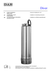
3” MICRA HS it 3” MICRA HS Istruzioni d’installazione e uso en 3” MICRA HS Installation and operating instructions de 3” MICRA HS Installations-und bedienungsanleitungen es 3” MICRA HS Instrucciones de instalación y uso 1 IT 2 IT 1 Applicazioni Le pompe MICRA HS sono state progettate per il pompaggio di liquidi non densi, puliti, non aggressivi, non esplosivi e non contenenti particelle solide, erba, fibre e sabbia in quantità maggiori ai 30g/m3. Applicazioni tipiche: • approvvigionamento idrico per: uso domestico, impianti idrici di piccole dimensioni, piccoli sistemi di irrigazione. • trasferimento di liquidi in serbatoi. • aumento pressione. Informazione valida per tutti i modelli: Il contenuto massimo di sabbia nell’acqua non deve superare i 30 g/m3. Una più alta concentrazione di sabbia ridurrà drasticamente la vita della pompa e aumenterà il rischio di blocco e di intervento continuo delle protezioni con conseguente bruciatura del motore. 2 Caratteristiche tecniche Fattore di potenza: PF=1. Valori del PH: Da 6 a 7. Cavo motore: 1.4 m, 3 x 1 mm2, PE. Temperatura del liquido: La temperatura del liquido pompato non deve eccedere i 35°C. Dimensione bocca pompa: DNM 1”. Diametro pompa: 74mm. Diametro pozzo: Minimo 76mm. Profondità di installazione: Massimo 90 m sotto il livello statico dell’acqua. Peso netto: Massimo 10 kg. 2.1 Immagazzinamento Temperatura di immagazzinamento: da -20°C a +60°C. 2.1.1 Protezione antigelo Se è necessario immagazzinare la pompa dopo l’uso, conservarla in un luogo non esposto al gelo. Il motore non deve essere immagazzinato se non è stato prima riempito con apposito liquido. 3 Preparazione I motori sommersi 3” Tesla s.r.l. sono dotati di cuscinetti lubrificati ad acqua. Non è necessaria ulteriore lubrificazione. I motori sommersi vengono riempiti con uno speciale liquido antigelo fino ad una temperatura di -20°C, idoneo a prevenire la formazione di batteri. 3.1 Requisiti di posizionamento La pompa è stata progettata per l’installazione verticale e orizzontale. L’albero della pompa, tuttavia, non deve mai trovarsi al di sotto del piano orizzontale. Se la pompa è installata in posizione orizzontale, ad es. in vasca, essa deve essere dotata di camicia di raffreddamento. 3.2 Raffreddamento/temperatura liquido pompato Per garantire il necessario raffreddamento del motore, è importante mantenere la temperatura massima del liquido a 35°C in tutte le condizioni. Nota: il diametro del pozzo deve essere di almeno 76 mm (circa 3”). Il motore deve sempre essere installato al di sopra del filtro del pozzo. Se viene utilizzata una camicia di raffreddamento, la pompa può essere installata liberamente nel pozzo. 3 IT 4 Collegamenti elettrici 4.1 Caratteristiche generali Il collegamento elettrico va eseguito da personale qualificato e, conformemente alla normativa vigente. L’apparecchio non è destinato ad essere usato da persone (bambini compresi) le cui capacità fisiche sensoriali o mentali siano ridotte , oppure con mancanza di esperienza o di conoscenza a meno che esse abbiano potuto beneficiare attraverso l’intermediazione di una persona responsabile della sicurezza , di sorveglianza o di istruzioni riguardanti l’uso dell’apparecchio. I bambini devono essere sorvegliati per sincerarsi che non giochino con l’apparecchio. Prima di operare sulla pompa, accertarsi di avere tolto l’alimentazione elettrica e che non possa essere accidentalmente ripristinata. Collegare a terra la pompa. La pompa deve essere collegata ad un interruttore di rete esterno con una distanza minima fra i contatti di 3 mm su tutti i poli. Sulla targhetta del motore-pompa sono riportati la tensione, la corrente nominale massima e il fattore di potenza (PF). Se la pompa è alimentata da una rete elettrica dove è presente un interruttore differenziale (ELCB) come ulteriore protezione, tale interruttore deve intervenire quando siano presenti correnti verso terra con componente continua (correnti DC pulsanti). Tensione di alimentazione: 1 x 200-240 V -10%/+6%, 50/60Hz, PE. L’assorbimento di corrente può venire misurato solo con strumenti in grado di effettuare letture di valori RMS. In caso vengano utilizzati altri strumenti, il valore rilevato differirà da quello effettivo. 5 Installazione 5.1 Dimensione cavo Il calo di tensione del 4% è conforme alle norme CEI-EN 60204-1. Dal calcolo scaturiscono le seguenti lunghezze massime del cavo, ad una tensione di alimentazione di 230 V. Lunghezza massima del cavo [m] Motore (P1) IN [kW] [A] 1,5 mm2 2,5 mm2 4 mm2 6 mm2 Dimensioni del cavo MIN 1 6,7 85 140 220 330 MAX 2,2 8,3 70 110 180 260 5.2 Cavo sommerso di alimentazione Si raccomanda di giuntare il cavo del motore mediante il kit di giunzione. Kit per la giunzione dei cavi Lunghezza del cavo [m] Sezione del cavo [mm2] Modello L30 1,5 Tutti i modelli L60 1,5 Tutti i modelli L90 1,5 Tutti modelli 302 (escluso 302-8) e 303 (escluso 303-5,303-6) L90 2,5 302-8;303-5,303-6;304-3;304-4 Tesla offre già la configurazione con motore, giunzione e cavo schermato (vedere codici disponibili). 4 IT 5.3 Profondità di installazione Max. profondità di installazione sotto il livello statico dell’acqua: 90 m. Min. profondità di installazione sotto il livello dinamico dell’acqua: • Installazione verticale: All’avviamento e durante il funzionamento la pompa deve essere completamente sommersa nell’acqua. • Installazione orizzontale: La pompa deve essere installata e funzionare ad almeno 0,5 m sotto il livello dinamico dell’acqua. Nel caso ci sia il rischio che la pompa venga coperta da fango, la pompa deve essere dotata di camicia di raffreddamento. 5.4 Installazione della pompa nel pozzo Si raccomanda di fissare la pompa mediante una fune di sicurezza che non sia tesa. Fissarla all’imbocco del pozzo tramite fermacavi. Nota: non movimentare la pompa mediante il cavo del motore. 6 Primo avviamento Assicurarsi che il pozzo abbia una capacità d’acqua minima corrispondente alla portata della pompa scelta. Non avviare la pompa fino a quando essa non sia completamente sommersa dal liquido. Avviare la pompa e mantenerla in funzione sino a quando il liquido pompato non fuoriesca perfettamente pulito, altrimenti potrebbero verificarsi occlusioni della valvola di non ritorno e intasamenti della pompa. 7 Funzionamento 7.1 Portata minima Per assicurare il corretto raffreddamento del motore, la portata minima non va mai impostata su un valore inferiore a 0.25 m3/h Un calo di portata improvviso potrebbe essere stato causato dal fatto che la pompa sta pompando più acqua di quanta il pozzo possa fornirne. E’ necessario, allora, fermare la pompa e modificare la portata, agendo sulla valvola di mandata, in accordo alle caratteristiche del pozzo. 7.2 Protezione incorporata Le protezioni sono incorporate all’interno dell’Active Driver 230 V / 10.5 Amp. / 110 Hz (leggere manuale di istruzione allegato). L’inverter è gia impostato a 110 Hz all’accensione del sistema. 8 Manutenzione e assistenza 8.1 Pompe DAB contaminate Nota: se una pompa è stata utilizzata con un liquido nocivo alla salute o tossico, la pompa viene classificata come “contaminata”. Nel richiedere a DAB di effettuare assistenza sulla pompa, è necessario fornire dettagli sul liquido pompato, prima ancora che la pompa venga inviata al servizio di assistenza. In caso contrario, DAB può rifiutarsi di accettare la pompa per eseguire la manutenzione. 5 EN 1 Applications MICRA HS pumps have been designed to pump clean, non-aggressive, non-explosive, non-dense liquids which do not contain solid particles, grass, fibres or sand in quantities of more than 30g/m3. Typical applications: • water supplies for: domestic use, small water supply systems, small irrigation systems. • transferring liquids to tanks. • pressure boosting. Information valid for all models: The maximum sand content in the water must not exceed 30 g/m3. High sand concentrations will drastically reduce the pump’s lifetime and increase the risk of seizing and continual tripping of the overload devices, causing the motor to burn out. 2 Technical characteristics Power factor: PF=1. pH values: From 6 to 7. Motor power cable: 1.4 m, 3 x 1 mm2, PE. Liquid temperature: The temperature of the pumped liquid must not exceed 35°C. Pump port diameter: DNM 1”. Pump diameter: 74 mm. Well diameter: Minimum 76 mm. Installation depth: Maximum 90 m below the static water level. Net weight: Maximum 10 kg. 2.1 Storage Storage temperature: from -20°C to +60°C. 2.1.1 Protection against frost If the pump has to be placed in store after use, keep it in a place where temperatures do not fall below zero. The motor must be filled with the specific liquid before being placed in store. 3 Preparation Tesla s.r.l. 3” submersible motors are fitted with water-lubricated bearings. No further lubrication is required. Submersible motors are filled with a special anti-freeze liquid providing protection down to a temperature of -20°C which will also prevent the formation of bacteria. 3.1 Positioning requirements The pump has been designed for vertical and horizontal installation. However, the pump shaft must never be below the horizontal plane. If the pump is installed horizontal, in a tank for example, it must be fitted with a cooling jacket. 3.2 Pumped liquid temperature/cooling To ensure that the motor is kept cool, the maximum temperature of the liquid must be kept at 35°C in all conditions. Note: the well diameter must be at least 76 mm (about 3”). The motor must always be installed above the well filter. If a cooling jacket is used, the pump can be installed in any position in the well. 6 EN 4 Electrical connections 4.1 General characteristics The electrical connection must be made by qualified staff in accordance with the relevant legal requirements. The device is not intended for use by persons (including children) with below-normal physical, sensorial or mental capacities, or with insufficient experience or know-how, unless they have received supervision or instruction in use of the device from a person in charge of safety. Children must be supervised to ensure that they do not play with the device. Before working on the pump, check that you have disconnected the electricity supply and it cannot be accidentally restored. Connect the pump to the electrical earth. The pump must be connected to an external mains supply switch with a breaking distance between contacts of at least 3 mm on all poles. The pump unit nameplate is marked with the voltage, the maximum rated current and the power factor (PF). If the pump is supplied by an electrical system fitted with a differential safety breaker (ELCB) providing additional protection, this breaker must trip in the event of ground currents with a direct current component (pulsed DC currents). Power supply voltage: 1 x 200-240 V -10%/+6%, 50/60Hz, PE. Current absorption can only be measured with instruments capable of reading RMS values. If instruments of different kinds are used, the value measured will not be the effective value. 5 Installation 5.1 Cable size The voltage drop of 4% complies with the CEI-EN 60204-1 standards. The calculations provide the following maximum cable lengths, at a power supply voltage of 230 V. Maximum cable length [m] Motor (P1) IN [kW] [A] 1,5 mm2 2,5 mm2 4 mm2 6 mm2 Cable size MIN 1 6,7 85 140 220 330 MAX 2,2 8,3 70 110 180 260 5.2 Submersible power supply cable Joints in the motor cable must be made using the relative kit. Cable joint kit Length of cable [m] Cable cross-section [mm2] Model L30 1,5 All models L60 1,5 All models L90 1,5 All 302 (except 302-8) and 303 (except 303-5,303-6) models L90 2,5 302-8;303-5,303-6;304-3;304-4 Tesla offers a pre-assembled package with motor, joint and shielded cable (see codes available). 7 EN 5.3 Installation depth Max. installation depth below static water level: 90 m. Min. installation depth below dynamic water level: • Vertical installation: The pump must be completely submerged in the water at start-up and during operation. • Horizontal installation: The pump must be installed and operate at least 0.5 m below the dynamic water level. If there is a risk that the pump may be covered with mud, it must be fitted with a cooling jacket. 5.4 Installing the pump in the well The pump should be fixed with a safety cable which must not be taut. Fix it to mouth of the well by means of a cable clamp. Note: do not move the pump around by the motor power supply cable. 6 First start-up Ensure that the pump has a minimum water delivery capacity equal to the flow rate of the chosen pump. Do not start the pump until it is completely submerged in the liquid. Start the pump and operate it until the pumped liquid comes out completely clean. Otherwise the check valve may be blocked or the pump may be fouled. 7 Operation 7.1 Minimum flow rate To ensure that the motor is cooled effectively, the minimum flow rate must never be set below a value of 0.25 m3/h. Any sudden reduction in flow rate might be caused by the fact that the pump is delivering more water than the well is able to supply. In this case, stop the pump and use the delivery valve to regulate the flow-rate to suit the well. 7.2 Built-in protective devices The protective devices are incorporated in the Active Driver 230 V / 10.5 Amp. / 110 Hz (read the attached instruction manual). The inverter is already set at 110 Hz when the system is switched on. 8 Maintenance and service 8.1 Contaminated DAB pumps Note: if a pump has been used with a harmful or toxic liquid, the pump is classified as “contaminated”. When contacting DAB to request service for the pump, provide details of the liquid which has been pumped even before the pump is sent to the after-sales service. Otherwise, DAB may refuse to take delivery of the pump for maintenance. 8 DE 1 Anwendungen Die Pumpen MICRA HS sind für das Pumpen von Flüssigkeiten konzipiert, die nicht dickflüssig, nicht aggressiv, nicht explosiv sind und keine festen Partikel, Gras, Fasern und Sand in höheren Mengen als 30 g/m3 enthalten. Typische Anwendungen: • Wasserversorgung für: Haushalte, kleine Wasseranlagen, kleine Bewässerungssysteme. • Beförderung von Flüssigkeiten in Tanks. • Druckerhöhung. Informationen für alle Modelle: Der maximale Sandgehalt im Wasser darf 30 g/m3 nicht übersteigen. Ein höherer Sandgehalt verringert drastisch die Lebensdauer der Pumpe und erhöht die Gefahr, dass die Schutzvorrichtungen blockieren und ununterbrochen eingreifen und der Motor durchbrennt. 2 Technische Merkmale Leistungsfaktor: PF=1. pH-Werte: Von 6 bis 7. Motorkabel: 1,4 m, 3 x 1 mm2, PE. Flüssigkeitstemperatur: Die Temperatur der Pumpflüssigkeit darf 35 °C nicht übersteigen. Abmessungen der Pumpenöffnung: DNM 1”. Pumpendurchmesser: 74 mm. Brunnendurchmesser: Mindestens 76 mm. Installationstiefe: Höchstens 90 m unter dem statischen Wasserstand. Nettogewicht: Maximal 10 kg. 2.1 Lagerung Lagerungstemperatur: von –20 °C bis +60 °C. 2.1.1 Frostschutz Falls die Pumpe nach dem Gebrauch gelagert werden muss, ist sie an einem frostfreien Ort aufzubewahren. Der Motor darf nur gelagert werden, wenn er zuvor mit einer geeigneten Flüssigkeit gefüllt wurde. 3 Vorbereitung Die Tauchmotoren 3” Tesla s.r.l. sind mit wassergeschmierten Lagern ausgestattet. Es ist keine weitere Schmierung erforderlich. Die Tauchmotoren werden mit einer speziellen Frostschutzflüssigkeit für Temperaturen bis –20 °C gefüllt, die zugleich die Entstehung von Bakterien verhindert. 3.1 Anforderungen an die Aufstellung Die Pumpe ist für eine vertikale und horizontale Installation konzipiert. Die Pumpenwelle darf jedoch niemals unterhalb der horizontalen Fläche liegen. Wenn die Pumpe horizontal installiert wurde, beispielsweise in einem Becken, muss sie mit einem Kühlmantel ausgestattet sein. 3.2 Kühlung/Temperatur der Pumpflüssigkeit Um eine ausreichende Motorkühlung zu gewährleisten, ist es wichtig, dass die Höchsttemperatur der Flüssigkeit unter allen Bedingungen auf 35 °C gehalten wird. Anmerkung: Der Brunnendurchmesser muss mindestens 76 mm betragen (zirka 3“). Der Motor muss immer oberhalb des Filters der Pumpe installiert werden. Wenn ein Kühlmantel verwendet wird, muss die Pumpe frei im Brunnen installiert werden. 9 DE 4 Elektrische Anschlüsse 4.1 Allgemeine Merkmale Der elektrische Anschluss ist von qualifiziertem Fachpersonal im Einklang mit den geltenden Vorschriften auszuführen. Das Gerät ist nicht für den Gebrauch durch Personen (einschließlich Kinder) mit eingeschränkten körperlichen, geistigen und sensorischen Fähigkeiten, mangelnder Erfahrung oder Kenntnissen bestimmt, es sei denn, sie werden beim Gebrauch des Gerätes durch eine Person, die für ihre Sicherheit verantwortlich ist, beaufsichtigt und angeleitet. Kinder sind zu beaufsichtigen, um sicherzustellen, dass sie nicht mit dem Gerät spielen. Vor Arbeiten an der Pumpe sicherstellen, dass die Stromversorgung getrennt wurde und nicht versehentlich wieder hergestellt werden kann. Die Pumpe erden. Die Pumpe ist an einen externen Netzschalter mit einem Mindestabstand von 3 mm zwischen den Kontakten und auf allen Polen anzuschließen. Auf dem Typenschild des Pumpenmotors sind Spannung, maximaler Nennstrom und Leistungsfaktor (PF) angegeben. Wenn die Pumpe über ein Stromnetz versorgt wird, in dem ein Fehlerstrom-Schutzschalter (ELCB) als weiterer Schutz installiert ist, muss dieser Schalter auslösen, wenn Erdströme mit Gleichanteil (DC-Anteil gepulste Ströme) vorliegen. Versorgungsspannung: 1 x 200-240 V -10%/+6%, 50/60Hz, PE. Die Stromaufnahme darf nur mit Instrumenten gemessen werden, die in der Lage sind, die RMS-Werte zu messen. Werden andere Instrumente verwendet, unterscheidet sich der gemessene Wert von dem tatsächlichen. 5 Installation 5.1 Kabelgröße Der Spannungsabfall von 4 % entspricht den Normen IEC-EN 60204-1. Die Berechnungen ergeben folgende Höchstlängen für das Kabel bei einer Versorgungsspannung von 230 V. Höchstlänge des Kabels [m] Motor (P1) IN [kW] [A] 1,5 mm2 2,5 mm2 4 mm2 6 mm2 Kabelgröße MIN 1 6,7 85 140 220 330 MAX 2,2 8,3 70 110 180 260 5.2 Unterwasserkabel zur Versorgung Es wird empfohlen, das Motorkabel mit dem Verbindungsbausatz anzufügen. Bausatz zur Verbindung der Kabel Länge des Kabels [m] Kabelquerschnitt [mm2] Modell L30 1,5 Alle Modelle L60 1,5 Alle Modelle L90 1,5 Alle Modelle 302 (außer 302-8) und 303 (außer 303-5, 303-6) L90 2,5 302-8;303-5,303-6;304-3;304-4 Tesla bietet den Pumpen bereits mit Motor + Verbindung + Kabel an (siehe verfügbare Artikelcodes). 10 DE 5.3 Installationstiefe Max. Installationstiefe unter dem statischen Wasserstand: 90 m. Min. Installationstiefe unter dem dynamischen Wasserstand: • Vertikale Installation: Beim Start und während des Betriebs muss die Pumpe vollständig ins Wasser eingetaucht sein. • Horizontale Installation: Die Pumpe muss mindestens 0,5 m unter dem dynamischen Wasserstand installiert und betrieben werden. Falls die Gefahr besteht, dass die Pumpe von Schlamm bedeckt werden könnte, ist sie mit einem Kühlmantel auszustatten. 5.4 Installation der Pumpe im Brunnen Es wird empfohlen, die Pumpe mit Hilfe eines nicht straff gespannten Sicherheitsseils zu fixieren. Mit Kabelschellen an der Brunnenöffnung befestigen. Anmerkung: Die Pumpe nicht mit Hilfe des Motorkabels bewegen. 6 Erste Inbetriebnahme Sicherstellen, dass der Brunnen ein Mindestfassungsvermögen an Wasser aufweist, das der Fördermenge der gewählten Pumpe entspricht. Die Pumpe nicht starten, bevor sie vollständig in die Flüssigkeit eingetaucht ist. Die Pumpe starten und in Betrieb halten, bis die Pumpflüssigkeit vollständig sauber austritt, andernfalls könnten das Rückschlagventil und die Pumpe verstopfen. 7 Betrieb 7.1 Mindestfördermenge Zur korrekten Kühlung des Motors darf die Mindestfördermenge nicht auf einen Wert unter 0,25 m3/h eingestellt werden. Ein plötzlicher Abfall der Fördermenge könnte dadurch verursacht sein, dass die Pumpe mehr Wasser pumpt, als der Brunnen liefern kann. In diesem Fall muss die Pumpe angehalten und ihre Fördermenge geändert werden. Dazu wird das Vorlaufventil entsprechend den Eigenschaften des Brunnens eingestellt. 7.2 Eingebaute Schutzvorrichtungen Die Schutzvorrichtungen sind im PWM 230 V /10,5 Amp. /110 Hz eingebaut (siehe beiliegende Bedienungsanleitung). Der Inverter ist bereits auf 110 Hz bei Start des Systems eingestellt. 8 Wartung und Kundendienst 8.1 Kontaminierte DAB-Pumpen Anmerkung: Wenn eine Pumpe mit einer gesundheitsschädlichen oder giftigen Flüssigkeit verwendet wurde, wird die Pumpe als „kontaminiert“ bezeichnet. Wird der Kundendienst von DAB für die Pumpe angefordert, sind detaillierte Angaben zur Pumpflüssigkeit zu machen, bevor die Pumpe an den Kundendienst geschickt wird. Andernfalls kann DAB die Annahme der Pumpe zur Durchführung der Wartungsarbeiten verweigern. 11 ES 1 Aplicaciones Las bombas MICRA HS se diseñaron para bombear líquidos no densos, limpios, no agresivos, no explosivos y que no contengan sólidos, hierba, fibras ni arena en una cantidad que supere los 30g/m3. Aplicaciones típicas: • abastecimiento hídrico para: uso doméstico, sistemas hídricos de pequeñas dimensiones, pequeños sistemas de riego. • trasiego de líquidos en depósitos. • aumento de presión. Información válida para todos los modelos: El contenido máximo de arena en el agua no debe superar los 30 g/m3. Una concentración más alta de arena reducirá drásticamente la vida de la bomba y aumentará el riesgo de bloqueo y el accionamiento continuo de las protecciones pudiendo quemar el motor. 2 Características técnicas Factor de potencia: PF=1. Valores del PH: de 6 a 7. Cable motor: 1.4 m, 3 x 1 mm2, PE. Temperatura del líquido: La temperatura del líquido bombeado no debe superar 35°C. Dimensión boca de la bomba: DNM 1” Diámetro de la bomba: 74mm. Diámetro del pozo: Mínimo 76mm. Profundidad de instalación: Máximo 90 m bajo el nivel estático del agua. Peso neto: Máximo 10 kg. 2.1 Almacenamiento Temperatura de almacenamiento: de -20°C a +60°C. 2.1.1 Protección anticongelante Si es necesario almacenar la bomba después de su uso, consérvela en un lugar que no esté expuesto al hielo. El motor no debe almacenarse si antes no se llenó con el líquido correspondiente. 3 Preparación Los motores sumergidos 3” Tesla s.r.l. montan cojinetes lubricados por agua. No requieren ninguna otra lubricación. Los motores sumergidos se llenan con un líquido anticongelante hasta una temperatura de -20°C, idóneo para prevenir la formación de bacterias. 3.1 Requisitos de posicionamiento La bomba ha sido diseñada para instalarse vertical y horizontalmente. Sin embargo, el eje de la bomba no debe quedar nunca por debajo del plano horizontal. Si la bomba está instalada en posición horizontal, por ejemplo en un depósito, deberá incorporar una camisa de refrigeración. 3.2 Refrigeración/temperatura líquido bombeado Para garantizar la refrigeración necesaria del motor, es importante mantener la temperatura máxima del líquido a 35°C en cualquier condición. Nota: el diámetro del pozo debe ser de al menos 76 mm (aprox. 3”). El motor siempre debe estar instalado por encima del filtro del pozo. Si se utiliza una camisa de refrigeración, la bomba no puede instalarse libremente en el pozo. 12 ES 4 Conexiones eléctricas 4.1 Características generales La conexión eléctrica debe ser hecha por personal experto y conforme a la normativa vigente. El aparato no está destinado para ser utilizado por personas (niños incluidos) cuyas capacidades físicas, sensoriales o mentales sean reducidas, o bien que sean inexpertos o sin conocimiento, salvo que sean supervisados por una persona responsable de su seguridad, que les controle y les dé las instrucciones oportunas para utilizar el aparato. Controle que los niños no jueguen con el aparato. Antes de reparar la bomba, asegúrese de haber desconectado la alimentación eléctrica y que no pueda activarse accidentalmente. Conecte la bomba a tierra. La bomba debe conectarse a un interruptor de red exterior con una distancia mínima entre los contactos de 3 mm en todos los polos. En la placa del motor-bomba se indican la tensión, la corriente nominal máxima y el factor de potencia (PF). Si la bomba es alimentada desde una red eléctrica en la cual hay un interruptor diferencial (ELCB) como ulterior protección, dicho interruptor debe intervenir cuando hay corrientes hacia tierra con componente continuo (corrientes DC pulsatorias). Tensión de alimentación: 1 x 200-240 V -10%/+6%, 50/60Hz, PE. La absorción de corriente puede medirse con instrumentos capaces de leer valores RMS. En caso que se utilicen otros instrumentos, el valor medido será distinto de aquel efectivo. 5 Instalación 5.1 Dimensión cable La disminución de tensión del 4% es conforme a las normas CEI-EN 60204-1. Del cálculo resultan las siguientes longitudes máximas del cable, a una tensión de alimentación de 230 V. Longitud máxima del cable [m] Motor (P1) IN [kW] [A] 1,5 mm2 2,5 mm2 4 mm2 6 mm2 Tamaño del cable MIN 1 6,7 85 140 220 330 MAX 2,2 8,3 70 110 180 260 5.2 Cable sumergido de alimentación Se recomienda empalmar el cable del motor mediante el juego de empalme. Juego para el empalme de los cables Longitud de cable [m] Sección del cable [mm2] Modelo L30 1,5 Todos los modelos L60 1,5 Todos los modelos L90 1,5 Todos los modelos 302 (excluido 302-8) y 303 (excluido 303-5,303-6) L90 2,5 302-8;303-5,303-6;304-3;304-4 Tesla ya ofrece la bomba con motor + empalme + cable (ver los códigos disponibles). 13 ES 5.3 Profundidad de instalación Profundidad máx. de instalación bajo el nivel estático del agua: 90 m. Profundidad mín. de instalación bajo el nivel dinámico del agua: • Instalación vertical: en el momento del arranque y durante el funcionamiento la bomba debe sumergirse completamente en el agua. • Instalación horizontal: La bomba debe instalarse y funcionar al menos a 0,5 m bajo el nivel dinámico del agua. En el caso que exista el riesgo que la bomba quede cubierta con lodo, la bomba deberá montar la camisa de refrigeración. 5.4 Instalación de la bomba en el pozo Se recomienda fijar la bomba con un cable de seguridad que no esté tenso. Fijarla en la embocadura del pozo con un sujetador de cables. Nota: no desplazar la bomba mediante el cable del motor. 6 Primera puesta en marcha Asegúrese de que el pozo tenga una capacidad de agua mínima correspondiente al caudal de la bomba escogida. No arranque la bomba antes de que esté completamente sumergida por el líquido. Arranque la bomba y manténgala en funcionamiento hasta que el líquido bombeado salga perfectamente limpio, por el contrario podrían producirse obstrucciones de la válvula antirretroceso y el atascamiento de la bomba. 7 Funcionamiento 7.1 Caudal mínimo Para asegurar la refrigeración correcta del motor, el caudal mínimo nunca debe configurarse por debajo de 0,25 m3/h. Una disminución de caudal improviso podría ser causada porque la bomba está bombeando más agua de lo que el pozo pueda proporcionar. Entonces, es necesario detener la bomba y modificar el caudal, actuando sobre la válvula de impulsión, de acuerdo con las características del pozo. 7.2 Protección incorporada Las protecciones se incorporan dentro del PWM 230 V /10.5 Amp. /110 Hz (lea el manual de instrucciones adjunto). El inverter ya está configurado en 110 Hz para el encendido del sistema. 8 Mantenimiento y asistencia 8.1 Bombas DAB contaminadas Nota: Si una bomba ha sido utilizada con un líquido perjudicial para la salud o tóxico, la bomba se clasifica como “contaminada”. Al solicitar a DAB que realice la asistencia técnica de la bomba, hay que proporcionar los detalles sobre el líquido bombeado, antes de que la bomba se envíe al servicio de asistencia. Por el contrario, DAB podría no aceptar la bomba para realizarle el mantenimiento. 14 Dichiarazione di conformità – Declaration of conformity – Konformitatserklarung – Declaración de conformidad it Dichiarazione di Conformità DAB Pumps S.p.A, con sede a Mestrino - Padova - Italia, dichiara che i prodotti descritti sotto Pompe sommerse Micra HS sono conformi alle disposizioni delle seguenti direttive europee e alle disposizioni nazionali di attuazione Bassa Tensione 2006/95/CE e successive modifiche Compatibilità Elettromagnetica 2004/108/CE e successive modifiche e conformi alle seguenti norme tecniche EN 60335-1, EN 60335-2-41 EN 61000-3-2, EN 61000-3-3 en Declaration of Conformity DAB Pumps S.p.A., with headquarters Mestrino - Padova - Italy, hereby declares that the following products Submersible Pumps Micra HS comply with the provisions of the following European Directives and with the regulations transposing them into national law Low Voltage Directive 2006/95/EEC and subsequent amendments Electromagnetic Compatibility Directive 2004/108/CE and subsequent amendments and with the following technical standards EN 60335-1, EN 60335-2-41 EN 61000-3-2, EN 61000-3-3 de Konformitatserklarung DAB Pumps srl, mit Sitz in Mestrino - Padova – Italien, erklart, dass die nachfolgend beschriebenen Produkte. Pumpen Micra HS Den Vorschriften der folgenden europaischen Richtlinien und nationalen Durchfuhrungsbestimmungen Niederspannungsrichtlinie 2006/95//EEC und nachfolgenden Anderungen Elektromagnetische Kompatibilitat 2004/108/CE und nachfolgenden Anderungen Sowie den folgenden technischen Vorschriften entsprechen EN 60335-1, EN 60335-2-41 EN 61000-3-2, EN 61000-3-3 es Declaración de Conformidad DAB Pumps S.p.A, con domicilio en Mestrino - Padua - Italia, declara que los productos descritos como Bombas sumergidas Micra HS son conformes a las disposiciones de las siguientes directivas europeas y las disposiciones nacionales de actuación Baja Tensión 2006/95/CE y siguientes actualizaciones Compatibilidad Electromagnética 2004/108/CE y siguientes actualizaciones y conformes a las siguientes normas técnicas EN 60335-1, EN 60335-2-41 EN 61000-3-2, EN 61000-3-3 Mestrino, 08/03/2011 Francesco Sinico (R&D Director) 15 60143852 DAB PUMPS S.P.A. – via Marco Polo, 14 35035 Mestrino - Padova - Italy Tel. (+39) 049.5125000 - Fax (+39) 049.5125950 http:// www.dabpumps.com Rev.00-03/11 16


