1
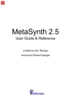
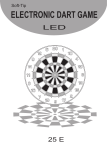
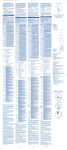
cod.A204
MICRO8
ITALIANO
MANUALE DEL MICRO8 E ACCESSORI
ENGLISH
MANUAL FOR THE MICRO8 AND ACCESSORIES
DEUTSCH
HANDBUCH MICRO8 UND ZUBEHÖR
FRANÇAIS LIVRET D'INSTRUCTIONS MICRO8 ET ACCESSOIRES
ESPAÑOL
MANUAL MICRO8 Y ACCESORIOS
2
ITALIANO
MANUALE DEL MICRO8 E ACCESSORI
INDICE
ENGLISH
MICRO8
4
CONTROL-LAMP 8
6
CONTROL-BALL 8
6
CODICI ARTICOLI
7
MANUAL FOR THE MICRO32 AND ACCESSORIES
CONTENTS
MICRO8
DEUTSCH
8
CONTROL-LAMP 8
10
CONTROL-BALL 8
10
ARTICLE CODES
11
HANDBUCH MICRO8 UND ZUBEHÖR
INHALTSVERZEICHNIS
FRANÇAIS
MICRO8
12
CONTROL-LAMP 8
14
CONTROL-BALL 8
14
ARTIKELNUMMERN
15
LIVRET D'INSTRUCTIONS MICRO8 ET ACCESSOIRES
TABLE DES MATIÈRES
ESPAÑOL
MICRO8
16
CONTROL-LAMP 8
18
CONTROL-BALL 8
18
CODES ARTICLES
19
MANUAL MICRO8 Y ACCESORIOS
INDICE
MICRO8
20
CONTROL-LAMP 8
22
CONTROL-BALL 8
22
CODIGOS ARTICULOS
23
3
Art.708 MICRO 8
Art.740
CONTROL-LAMP8
Art.729
CONTROL-BALL8
Art.440
MINI BOX
Art.416/LOW BOX-16B/LOW
Art.402 BOX-PING-PONG
Art.416 BOX-16B
Art.422 BOX-22B
Art.403 BOX-3B
ITALIANO
4
ITALIANO
MICRO8
NOTE PER L'INSTALLAZIONE
ALIMENTAZIONE: 185-240V~
30 mA.
50-60Hz
AT T E N Z I O N E : P R I M A D I A P R I R E
L'INVOLUCRO TOGLIERE LA TENSIONE DI
ALIMENTAZIONE.
Per visualizzare il totalizzatore di ogni singolo tavolo, tenere premuto il tasto numerato corrispondente. Per azzerare tutti i totalizzatori premere contemporaneamente
i tasti TOTAL e (-). Il valore massimo del totalizzatore generale è di 9 cifre
(999999999), mentre quello di ogni totalizzatore individuale è di 8 cifre
(99999999), dopodichè riparte da zero.
Poichè le cifre visualizzabili sono solo 7,
se i totalizzatori raggiungono 8 o 9 cifre,
non vengono visualizzate le cifre meno importanti di destra. Vengono comunque
spostati i punti decimali in modo da non
creare errori nella lettura.
Apparecchiatura in Classe II.
Il costruttore declina ogni responsabilità
in caso di manomissione alle proprie apparecchiature.
La presa di corrente deve essere in prossimità dell'apparecchiatura e facilmente
accessibile.
Se è necessario il collegamento permanente alla rete di alimentazione, questo
deve essere effettuato da personale qualificato che deve prevedere un dispositivo
di sezionamento esterno facilmente accessibile.
PROGRAMMAZIONE
Inserire la spina in una presa 230V e poi
accendere col tasto ON/OFF.
Prima di iniziare ad operare è bene eseguire tutta la programmazione in modo
che siano abilitate le funzioni che interessano.
Per iniziare la programmazione, girare nel
senso della freccia la chiave
INSTALLATION finchè inizia a lampeggiare la spia rossa (LED) situata sul tasto giallo TOTAL.
Nella programmazione vengono usati i tasti gialli per selezionare e modificare le 6
funzioni possibili che sono:
TOTAL
TOTALIZZATORI
Premendo il tasto TOTAL lampeggia il LED
situato sopra lo stesso.
Il display visualizza la somma dei totalizzatori degli 8 tavoli.
1
MONETARY
UNIT
UNITA' MONETARIA
Premendo questo tasto, sulla sinistra del
display lampeggia il numero "1", mentre
sulla destra viene visualizzato il valore
dell'UNITA' MONETARIA che può essere
modificato con i tasti (+) e (-) nei seguenti possibili valori: 0,05
0,10
0,20
0,50 1 2 5 10 20 50 100 200 500
1000.
Il valore dipende dalla valuta monetaria
della nazione ed anche dall'arrotondamento che si desidera avere
sull'impor to da pagare. Esempi: per
l’EURO 0,05 , USA 0,10 , RUSSIA 1 ,
GIAPPONE 10.
2
BOX BILIE (abilitazione)
BOX
Premendo questo tasto, sulla sinistra del
display lampeggia il numero "2".
I l M I C R O 8 p u ò e s s e re c o l l e g a t o a l
CONTROL-BALL8 il quale può controllare la presenza delle bilie per 8 biliardi
contenute in appositi BOX.
In questo passo di programmazione si definisce quali biliardi hanno il BOX per il
controllo delle bilie.
Premendo un tasto numerato (1-8) si può
accendere o spegnere il rispettivo LED
lampeggiante per definire, se acceso,
che il biliardo corrispondente ha il BOX
bilie. Per il collegamento dei BOX vedere
il capitolo "CONTROL-BALL8".
5
3
TARIFFA DI PARTENZA
Definisce l'importo minimo di
gioco che si desidera far pagare anche se il tavolo viene occupato per poco tempo.
4
TARIFFA ORARIA
E' la tariffa oraria normalmente
usata.
START
TARIFF
TARIFF
5
CLUB
TARIFF
TARIFFA ORARIA CLUB
E' una seconda tariffa oraria
che può essere utile in vari casi (soci club, ore notturne, giorni festivi, ecc.)
PROGRAMMAZIONE TARIFFE
Premere il tasto tariffa desiderato fra i 3
possibili (START TARIFF, TARIFF, CLUB
TARIFF). Sulla sinistra del display lampeggierà il numero corrispondente al tasto tariffa (3, 4 o 5) per indicare quale funzione è attiva. Scegliere poi a quale tavolo si desidera cambiare la tariffa premendo il tasto numerato corrispondente (1-8).
Il LED sul tasto lampeggierà ad indicare il
tavolo scelto. Infine variare la tariffa coi tasti (+) e (-). Per variare velocemente mantenere premuti gli stessi.
Ogni tariffa può essere variata da zero a
250 volte il valore dell'UNITA' MONETARIA
(programmata all'inizio).
Se tutti gli 8 tavoli devono avere la stessa
tariffa, per evitare di fare 8 programmazioni uguali è sufficiente programmare il tavolo numero "1" e poi mantenere premuto
per 5 secondi il tasto "1".
Eseguire la programmazione per tutti e 3 i
tipi di tariffa. Se la tariffa oraria club non
viene usata, si può programmarla uguale
alla tariffa oraria normale.
Per terminare la programmazione basterà
rigirare la chiave.
FUNZIONAMENTO
Prima di iniziare ad operare è bene sia
avvenuta la programmazione in modo che
siano abilitate le funzioni che interessano.
Inserire la spina in una presa 230V e
accendere col tasto ON/OFF.
Per far partire il conteggio premere START
e poi il num. del tavolo interessato. Lo
stesso vale con START CLUB per far
partire il conteggio con la tariffa oraria
club.
ITALIANO
Sul tasto numerato si accenderà il LED
ad indicare che è in conteggio. Se il conteggio è con tariffa club il led ha un leggero lampeggìo. Una volta comandato lo
START, si può cambiare in START CLUB o
viceversa entro il tempo di un minuto.
D u r a n t e i l c o n t e g g i o s i p u ò v e d e re
l'importo maturato fino a quel momento
da un tavolo semplicemente premendo il
suo numero (1-8).
Finito il gioco, per arrestare il conteggio
premere STOP e poi il num. interessato.
Sul display apparirà l'importo da pagare.
Nel caso venga usato il BOX bilie, quando questo viene richiuso (con tutte le bilie), sul MICRO8 lampeggia il LED sul tasto del biliardo interessato per indicare
la fine del gioco e che l'operatore deve
eseguire lo STOP prima di un'eventuale
altro START.
Se si comanda lo STOP di un tavolo che
ha il controllo delle bilie, senza che queste siano al loro posto, lo STOP viene accettato ma avviene una ripartenza automatica. Questo è utile per permettere lo
scambio di giocatori senza dover rimettere le bilie al loro posto. In questo caso
la ripartenza automatica non è CLUB e
quindi se il giocatore entrante è socio
club si ha un minuto di tempo per premere START CLUB e poi il numero tavolo.
Oltre ai totalizzatori visibili solamente
con la chiave (vedi programmazione), è
possibile visualizzare un ulteriore totalizzatore che può essere utile per il personale di servizio. Tale totalizzatore appare mantenendo premuto per più di 2 secondi il tasto TOTAL. Per azzerarlo, mentre si tiene premuto TOTAL premere anche il tasto (-).
In mancanza di energia elettrica potete
accendere il MICRO8 premendo con la
punta di una penna dentro al foro
B AT T E RY c h e è s i t u a t o a f i a n c o d i
ON/OFF.
La batteria interna è una comune batteria
a 9V alcalina (tipo 6LR61) e viene usata
solo premendo il tasto BATTERY. Può
mantenere acceso il MICRO8 per circa
15 ore e NON serve a mantenere i dati in
memoria ma solamente a permettere la visualizzazione degli importi in caso di
black-out elettrico. La sua durata è mediamente superiore ai 5 anni e per la sua
sostituzione è neccessario, dopo aver
staccato la spina di alimentazione elettrica, aprire il MICRO8 svitando le 4 viti sul
retro.
6
CONTROL-LAMP 8
ALIMENTAZIONE: 230V~ 50-60Hz 60mA.
Corrente di carico applicabile per ogni
via di lampade: 5A. Fusibile per ogni via
di lampade: 6,3A F.
ATTENZIONE: PRIMA DI APRIRE L'INVOLUCRO
TOGLIERE LA TENSIONE DI ALIMENTAZIONE
ANCHE ALL'IMPIANTO LAMPADE.
Apparecchiatura in classe II.
I collegamenti devono essere effettuati
da personale qualificato seguendo lo
schema in fig.1. Nell'impianto fisso di collegamento alla rete di alimentazione deve essere previsto un dispositivo di sezionamento con capacità adeguata al carico
lampade applicato.
Il CONTROL-LAMP8 può essere posto fino ad una distanza di 100 mt. dal
MICRO8. In dotazione c'è un sottile cavo
lungo 15 mt. Per distanze superiori sono
disponibili prolunghe, oppure è possibile
tagliare questo cavo ed allungarlo con 2
soli fili collegando un filo ai due conduttori centrali del cavo ed il secondo filo ai 2
conduttori laterali (il cavo ha 4 conduttori).
Sul retro del MICRO8 c'è una presa contrassegnata con CONTROL-LAMP per inserire il connettore del cavo.
Sulla scheda del CONTROL-LAMP8 un
LED rosso indica:
LED lampeggia: il collegamento con il
MICRO8 è OK.
LED sempre acceso: non c'è collegamento con il MICRO8.
LED spento: manca l'alimentazione al
CONTROL-LAMP8 oppure è guasto.
CONTROL-BALL 8
A L I M E N TA Z I O N E : 2 3 0 V ~ 5 0 - 6 0 H z
250mA MAX.
Fusibile di protezione primario: 1A F.
Tensione e corrente per ogni uscita BOX:
24Vac 2A MAX per 40ms.
Apparecchiatura in classe II.
ATTENZIONE: PRIMA DI APRIRE L'INVOLUCRO
TOGLIERE LA TENSIONE DI ALIMENTAZIONE.
I collegamenti devono essere effettuati
da personale qualificato seguendo lo
schema in fig.2. L'alimentazione 230V
del CONTROL-BALL8 deve essere sulla
stessa linea di alimentazione del MICRO8
in modo che siano spenti o accesi dal medesimo interruttore generale.
Il CONTROL-BALL8 controlla la presenza
delle bilie per 8 biliardi e può
essere posto fino ad una distanza di 100
ITALIANO
mt dal MICRO8. In dotazione c'è un
sottile cavo lungo 15 mt. Per distanze
s u p e r i o r i s o n o d i s p o n i b i l i p ro l u n g h e
oppure allungarlo seguendo le istruzioni
come per il CONTROL-LAMP8. Sul retro
del MICRO8 c'è una presa
contrassegnata CONTROL-BALL per
inserire il connettore del cavo. Al
CONTROL-BALL8 si possono collegare 8
BOX (cassetti) contenenti le bilie.
Nella programmazione del MICRO8, si deve
specificare su quali biliardi si desidera ci sia il
controllo delle bilie.
Questo permette la gestione di una parte
dei biliardi senza controllo bilie oppure di
altri giochi.
Il collegamento dal CONTROL-BALL8 ad
ogni BOX è con soli 2 fili ed in bassa
tensione. Inoltre nessun danno si verifica
per cortocircuiti o errati collegamenti. Il
BOX è un robusto contenitore in metallo
che contiene un vassoio con tutte le bilie.
Il BOX si apre solamente quando viene
comandato un inizio gioco (START) dal
MICRO8, permettendo così al giocatore
di estrarre il vassoio.
A fine gioco,
q u a n d o n e l B O X v i e n e re i n s e r i t o i l
vassoio con tutte le bilie e chiuso lo
sportello (se manca una bilia non si
chiude), il MICRO8 arresta il conteggio
del tempo e indica all'operatore la fine
del gioco facendo lampeggiare il LED sul
tasto del biliardo interessato.
I BOX bilie, anche se funzionanti con
sistema isolato a 24V, sono predisposti
internamente con faston per
collegamento all'impianto di terra.
Ci sono BOX per tutti i tipi di gioco:
vedere capitolo CODICI ARTICOLI.
Sulla scheda del CONTROL-BALL8 un
LED rosso indica:
LED lampeggia: il collegamento con il
MICRO8 è OK.
non
c'è
LED sempre acceso:
collegamento con il MICRO8.
manca l'alimentazione al
LED spento:
CONTROL-BALL8 oppure è guasto.
Al CONTROL-BALL8 possono essere
collegati anche dei semplici contenitori
per bilie nei quali l'estrazione del
vassoio provoca l'apertura di un
microinterruttore.
In questo caso lo
S TA R T d e l g i o c o a v v i e n e a u t o m a ticamente quando si estrae il vassoio. Se
si desidera che tale START automatico
sia CLUB, si può comandarlo prima o
e n t ro u n m i n u t o d a l l ' e s t r a z i o n e d e l
vassoio premendo lo START CLUB e poi il
num. interessato.
I due fili del
microinterruttore vanno collegati come i
due fili del BOX.
ITALIANO
7
SCHEDA
CONTROL-LAMP8
8 FUSIBILI 6,3A F 250 Vac
8
LAMP.
8
7
7
6
6
5
4
5
4
3
3
2
2
SCHEDA CONTROL-BALL8
6 5 4 3 2 1
Sezione fili
2
minimo 1mm
1
COMMON-BOX
SERIAL
LINE
230V
230 Vac 60mA
ALIMENTAZIONE
CONTROL-LAMP8
230 Vac
ALIMENTAZIONE LAMPADARI
FIG. 1 COLLEGAMENTI
CONTROL-LAMP8
8 7
1
COLLEGAMENTO
AL MICRO 8
FUSIBILE 1A F 250 Vac
230V
SERIAL
LINE
1
230 Vac 250mA
ALIMENTAZIONE
CONTROL-BALL8
2
3
FIG. 2 COLLEGAMENTI
CONTROL-BALL8
BOX
COLLEGAMENTO
AL MICRO 8
CODICI ARTICOLI
Art.708
Art.739
Art.740
Art.728
Art.729
Art.403
Art.403A
Art.404
Art. 409
Art. 409A
Art. 416
+Art. 446
Art. 416A
Art. 416B
Art. 422
Art. 402
Art. 440
MICRO 8 .
CONTROL-LAMP-4 per controllo 4 lampadari.
CONTROL-LAMP-8 per controllo 8 lampadari.
CONTROL-BALL-4 per controllo 4 BOX bilie.
CONTROL-BALL-8 per controllo 8 BOX bilie.
BOX-3B per INTERNAZIONALE (3x Ø61,5)
BOX-3B per ITALIANA (2xØ68 + 1xØ59).
BOX-4B per 4 bilie (4 x Ø61,5 mm)
BOX-9B per BOCCETTE INTERNAZ. (9x Ø61,5).
BOX-9B per BOCCETTE NAZIONALI (8 x Ø59 + 1 x Ø54 mm).
BOX-16B per POOL (16x Ø57)
SPESSORE 6mm per POOL con bilie Ø50-52 mm.
BOX-16B/52 per POOL INGLESE (16 x Ø50-52 mm).
BOX-16B/68 per PIRAMIDE RUSSA (16 x Ø68 mm).
BOX-22B per SNOOKER (22x Ø52-54).
BOX-PING-PONG per 2 racchette PING-PONG + pallina.
MINI BOX per PALLINO BOCCE o PALLINA PING-PONG (Ø 35-40 mm).
Le misure delle bilie sono le più usate e possono avere una tolleranza di ± 2 mm. Per misure
più piccole basta mettere sul fondo del Box uno spessore disponibile su richiesta.
ENGLISH
8
ENGLISH
MICRO8
NOTES ON THE INSTALLATION
FEED: 185-240V~ 50-60Hz 30 mA.
ATTENTION: REMOVE THE POWER SUPPLY
BEFORE OPENING THE CASE.
Equipment: Class II.
The producer declines every responsability
in case the equipment is tampered with.
The power outlet must be near the
appliance and easily accessible.
If the appliance has to be connected to the
power supply permanently, its connection
must be carried out by qualified personnel
who must install an external cutoff device
in an easily accessible position.
PROGRAMMING MICRO8
Insert the plug in a 230Vac outlet and then
use the ON/OFF button to turn the device
on.
Before using the machine, it would be
best to carry out all the programming so
that each function you wish to use will be
activated.
To s t a r t p r o g r a m m i n g , t u r n t h e
INSTALLATION key in the direction of the
arrow until the red LED situated on the
yellow TOTAL button starts flashing. The
yellow buttons are used during
programming for modifying the 6
available functions, which are:
TOTAL
TOTALS
By pressing the TOTAL button, its LED
will start flashing.
The display will show the sum of the
totals for the 8 tables.
To display the total for each table, keep
the button corresponding to the table
pressed.
To reset all totals, press the buttons
TOTAL and (-) together. The maximum
value of the overall total is made up of 9
digits (999999999), whilst the maximum
value of each single total is made up of
8 digits (99999999), after which they will
restart from 0. As only 7 digits are
displayed, if the totals reach 8 or 9
digits, the two least important digits to
the right will not be shown. Decimal
points will however move so as to avoid
creating errors whilst reading the
numbers.
1
MONETARY
UNIT
MONETARY UNIT
By pressing this button, the number "1"
will flash on the left of the display, whilst
the value of the monetary unit (currency)
will appear on the right which can be
changed by using the buttons (+) and
(-), as follows: 0,05 0,10 0,20 0,50 1
2 5 10 20 100 200 500 1000.
This value depends on the currency
used and the required rounding off of the
sum to be paid.
For example: EURO 0,05 , USA 0,10 ,
RUSSIA 1 , JAPAN 10.
2
BILLIARD BALL BOX (enable)
BOX
By pressing this button, the number "2"
will flash on the left of the display.
The MICRO 8 can be connected to a
CONTROL-BALL-8 which can control the
billiard balls contained in special BOXES
for 8 billiard tables.
In this programming step, you decide
wich billiards has the BOX to control the
balls.
By pressing a numbered button (1-8),
you can turn on or off the corresponding
flashing light. If it is on the
corresponding billiard table will have a
ball BOX. For connecting the BOXES,
refer to the chapter "CONTROL-BALL-8".
9
3
START TARIFF
This defines the minimum playing tariff which must be paid
even if the table is occupied
only for a short period.
4
HOURLY TARIFF
This is the hourly tariff normally
used.
START
TARIFF
TARIFF
5
CLUB
TARIFF
CLUB HOURLY TARIFF
This is a second hourly tariff
that can be useful for several
occasions (club members,
night hours, bank holidays,
etc.).
TARIFF PROGRAMMING.
Press the
required tariff button, amongst the three
possibilities (START TARIFF, TARIFF,
CLUB TARIFF).
The corresponding
number (3, 4 or 5) will flash on the left of
the display to signal which function has
been activated. Next select the table for
which the tariff has to be changed by
pressing the corresponding button (1-8).
The LED on the button will flash to
indicate the selected table. Change the
tariff using the buttons (+) or (-). To
change rapidly keep the button pressed.
Every tariff can be changed from 0 to 250
times the value of the MONETARY UNIT
(set at the beginning). If all 8 tables have
the same tariff, instead of programming 8
times, program table num. "1" and then
keep the button "1" pressed for 5 seconds.
Program all three types of tariff. If the
club tariff is not used, it can be set the
same as the normal tariff.
To exit the programming mode, turn the
key again.
OPERATING MICRO8
Before beginning to operate the unit, it
would be best to carr y out all the
programming so that each and every
operation you wish to use will be
activated.
Insert the plug in a 230VAC outlet and
then turn the unit on with the ON/OFF
button.
To start the counter press START followed
by the required table number. Do the
same for START CLUB if you want the
club tariff to be used.
ENGLISH
The LED on the numbered button will light
up to signal that it has started counting.
If the club tariff has been selected, the
led will flash slowly. Once the START button has been pushed, you will have one
minute to change to START CLUB or viceversa.
During the count, the sum due for each table can be shown at any moment by pressing the corresponding number (1-8).
Once the game is finished, you may stop
the count by pushing the STOP button
and then the table number involved. The
sum due will appear on the display.
If the ball BOX is being used, when it is
closed (with all the balls inside), the LED
on the button corresponding to the table
will flash to signal game over, the operator must press STOP before he can press
another START.
If the STOP is pressed for a table which
has control of the balls and these balls
are not in place, the STOP will be registered but there will be an automatic restart.
This is useful for letting the players change without having to put the balls back in
place. In this case, the automatic re-start
is not a CLUB rate, so if the new player is
a club member you will have one minute
to push START CLUB and then the table
number.
In addition to the totals which can be displayed using the key (see programming), another total can be displayed
which may be useful for service personnel. To display this total, keep the TOTAL
button pressed for two seconds. To reset
it, press the button TOTAL together with
the (-) button.
In the absence of electricity, you may turn
on the MICRO8 by pushing the point of a
pen into the BATTERY hole located on the
side of the ON/OFF button.
The internal battery is a normal 9V alkaline battery (type 6LR61) and is used only
when the BATTERY button is pressed. It
can keep the MICRO 8 on for approximately 15 hours but it is NOT meant for keeping the data in memory but to display
the sums due if a blackout occurs. It
usually lasts more than 5 years. To replace it, disconnect the power supply and
open the MICRO 8 by unscrewing the 4
screws on the back.
10
CONTROL-LAMP 8
FEED: 230V~ 50-60Hz 60mA.
Load of current for every lampsway: 5A.
Fuse for every way of lamps: 6,3A F.
ATTENTION: BEFORE OPENING THE CASE
REMOVE THE POWER SUPPLY FROM THE LAMP
INSTALLATION TOO.
Equipment: 2nd Class.
The connections must be carried out by
qualified personnel following the diagram
in fig. 1. If the appliance is connected
permanently to the power supply, a cutoff
device must be installed with an adequate
capacity according to the lamps
connected.
The CONTROL-LAMP8 may be positioned
up to a distance of one hundred metres
from the MICRO8. It comes equipped with
a thin cable fifteen metres in length.
Extension cords are available for greater
distances, or you may cut this cable and
lengthen it with only 2 wires, connecting
one wire with the two central cable's leads
and the second wire with the 2 lateral leads
(the cable has 4 leads).
On the back of the MICRO 8 there is a
connector marked CONTROL-LAMP for
inserting the connector.
On the CONTROL-LAMP8 board, a red
light indicates:
flashing light: the connection with
MICRO8 is correct.
light always on: the unit is not
connected with the MICRO8.
light off: the CONTROL-LAMP8 is either
broken or has not power feed.
CONTROL-BALL 8
FEED: 230V~ 50-60Hz 250mA MAX.
Primary fuse of protection: 1A F.
Tension for every exit: 24Vac.
MAX current for every exit: 2A AC for 40ms
about.
Equipment: 2nd Class.
ATTENTION: REMOVE THE POWER SUPPLY
BEFORE OPENING THE CASE.
The connections must be carried out by
qualified personnel according to the
diagram in fig. 2. The 230V power supply
of the CONTROL-BALL8 must be carried
out from the same line as the MICRO8 so
they can both be turned on and off by the
same main switch.
The CONTROL-BALL8 controls the
presence of the balls for 8 billiard tables
and may be positioned at a distance of one
hundred metres from the MICRO8.
ENGLISH
distance of one hundred metres from the
MICRO8. It comes equipped with a thin
cable fifteen metres long. For distances of
more than 15 metres, extension cords are
available, but you may also lengthen the
cable by following the instructions given
for the CONTROL-LAMP8. On the back of
the MICRO8 there is a connector marked
CONTROL-BALL for inserting the
connector. The CONTROL- BALL8 can be
connected with 8 BOXes (drawers) holding
the balls. Whilst programming the MICRO8,
you must specify which billiard tables require
ball control. This allows you to control a part
of the billiards tables without balls control
or other games.
The connection from the CONTROL- BALL8
to each BOX is carried out with just two
low-voltage wires.
In addition, no harm will be done in the
event of short-circuiting or mismanaged
connections. The BOX is a sturdy metal
container which holds a tray with all the
balls. The BOX opens only when it receives
a command (START) from the MICRO8 to
begin a game, and at that moment the
player can take the tray out. When the
game is over, and after the tray with ALL
the balls has been put back into the BOX
and the door has been closed (the door will
not close if even one ball is missing), the
MICRO8 stops the time count and tells the
operator that game is over by flashing the
red light on the button of the table involved.
Even through operating with a 24 Volts
insulating system, the ball BOXes are
equipped on the inside with a faston
device in order to be connected with the
electrical grounding system.
There are BOXes for all kinds of games.
See the section on "ARTICLE CODES".
On the CONTROL-BALL8 board, a red light
indicates:
flashing light: the connection with the
MICRO8 is correct.
light always on:
the unit is not
connected with the MICRO8.
light off: the CONTROL-BALL8 is either
broken or has no power feed.
The CONTROL-BALL8 may also be
connected to simple balls containers in
which the withdrawal of the tray turns on a
micro-switch. In this case, the game starts
automatically when the tray is taken out. If
you wish that automatic START to be a club
operation, you can set it before or within
one minute of the tray's extraction by
pushing the STARTCLUB button and then
the button for the table involved. The two
micro-switch wires are connected in the
same way as the two BOX wires.
ENGLISH
11
CONTROL-LAMP8
BOARD
8 FUSES 6,3A F 250 Vac
8
LAMP.
8
7
7
6
6
5
4
5
4
3
3
2
2
CONTROL-BALL8 BOARD
6 5 4 3 2 1
Wire section
2
1mm
COMMON-BOX
230 Vac 60mA
CONTROL-LAMP8
POWER FEED
HOOK-UP TO
THE MICRO 8
FUSE 1A F 250 Vac
230V
SERIAL
LINE
1
230 Vac 250mA
CONTROL-BALL8
POWER FEED
2
3
FIG. 2 CONTROL-BALL8
CONNECTIONS
1
SERIAL
LINE
230V
230 Vac
POWER FEED TO THE LAMPS
FIG. 1 CONTROL-LAMP8
CONNECTIONS
8 7
1
BOX
HOOK-UP TO
THE MICRO 8
ARTICLE CODES
Art. 708
Art. 739
Art. 740
Art. 728
Art. 729
Art. 403
Art. 403A
Art. 404
Art. 409
Art. 409A
Art. 416
+Art. 446
Art. 416A
Art. 416B
Art. 422
Art. 402
Art. 440
MICRO8 .
CONTROL-LAMP4 for controlling 4 lamps.
CONTROL-LAMP8 for controlling 8 lamps.
CONTROL-BALL4 for controlling 4 ball containers (BOX).
CONTROL-BALL8 for controlling 8 ball containers (BOX).
BOX-3B for CARAMBOL (3 balls Ø61,5 mm).
BOX-3B for ITALIANA (2 x Ø68 + 1 x Ø59 mm).
BOX-4B for 4 balls (4 x Ø61,5 mm).
BOX-9B for 9 balls (9 x Ø61,5 mm).
BOX-9B for 9 balls (8 x Ø59 + 1 x Ø54 mm).
BOX-16B for POOL, for controlling 16 balls (Ø57.2 mm).
SPACER 6mm in thickness for English Pool balls (Ø50-52 mm).
BOX-16B/52 for ENGLISH POOL, for controlling 16 balls (Ø50-52 mm).
BOX-16B/68 for RUSSIAN PYRAMID, for controlling 16 balls (Ø68 mm).
BOX-22B for SNOOKER, for controlling 22 balls (Ø52-54 mm).
BOX-PING-PONG for controlling 2 bats and one little ball.
MINI-BOX for controlling a little ball (Ø35-40 mm).
The measurements given for the balls are those most in use, and they may have a variance of
±2mm. For smaller sizes, insert a shim on the bottom of the Box; such provision is available
upon request.
DEUTSCH
12
DEUTSCH
MICRO8
ANMERKUNG ZUR INSTALLATION
STROMVERSORGUNG: 185-240V~ 5060Hz 30 mA.
ACHTUNG: VOR DEM ÖFFNEN DES GEHÄUSES
M Ü S S E N S I E D E N A P PA R AT V O N D E R
NETZSPANNUNG TRENNEN.
Apparatur der Klasse II.
Der Hersteller lehnt jede Verantwortung
im Falle einer Abänderung seiner Geräte
ab.
Der Stromanschluß sollte sich in der
Nähe der Apparatur befinden und leicht
zugänglich sein.
Falls ein fester Anschluß an das
Stromversorgungsnetz erforderlich ist,
muß dieser von Fachpersonal ausgeführt
werden, das eine Trennbuchse leicht
zugänglich anbringen sollte.
PROGRAMMIERUNG MICRO8
Verbinden sie den Netzstecker mit einer
230VAC-Steckdose und schalten sie dann
mit der Taste ON/OFF ein.
Vo r d e r I n b e t r i e b n a h m e s o l l t e d i e
gesamte Programmierung durch-geführt
werden, damit die gewünschten
Funktionen befähigt sind.
Um mit der Programmierung zu beginnen,
drehen Sie den Schlüssel INSTALLATION
in Pfeilrichtung, bis die rote
Kontrolleuchte (LED) auf der gelben Taste
TOTAL zu blinken beginnt. Während der
P ro g r a m m i e r u n g w e rd e n d i e g e l b e n
Tasten zu Wahl und Änderung der 6
möglichen Funktionen betätigt. Da wären:
TOTAL
ZÄHLWERKE
Durch Druck der Taste TOTAL fängt die
LED über derselben zu blinken an. Das
Display zeigt die Summe der Zählwerke
der 8 Tische an.
Zur Sicht des Zählwerkes jedes einzelnen
Tisches halten Sie die Taste mit der
entsprechenden Nummer gedrückt. Um
alle Zählwerke auf Null zu stellen, drücken
Sie gleichzeitig die Tasten TOTAL und (-).
Der höchste vom Hauptzählwerk
anzuzeigende Wert hat 9 Ziffern
( 9 9 9 9 9 9 9 9 9 ) , w ä h re n d d e r v o n d e n
Einzelzählwerken angegebene Wert 8
Ziffer n hat (99999999). Danach wird
wieder von Null angefangen. Da die
angezeigten Ziffern nur 7 sind, werden
auf den Zählwerken bei Erreichen der 8.
oder 9. Ziffer rechts die weniger wichtigen
nicht angezeigt. Es werden allerdings die
Dezimalstellen so versetzt, daß beim
Ablesen keine Fehler auftreten können.
1
MONETARY
UNIT
GELDEINHEIT
Bei Druck dieser Taste blinkt links auf
dem Display die Nummer "1", während
rechts der Wer t der GELDEINHEIT
angezeigt wird. Er kann mit den Tasten
(+) und (-) in den folgenden Werten
geändert werden: 0,05 0,10 0,20 0,50
1 2 5 10 20 50 100 200 500 1000.
Der Wert hängt von der Währungseinheit
des Landes und auch von der
Abrundung, die auf den zu zahlenden
Betrag angewendet werden soll, ab.
Beisp. für EURO 0,05 , USA 0,10 ,
RUßLAND 1 , JAPAN 10 .
2
KUGELBOX (Befähigung)
BOX
Bei Druck dieser Taste blinkt rechts auf
dem Display die Nummer "2". Der MICRO8
kann mit dem CONTROL-BALL8
verbunden werden, der das
Vorhandensein der Kugeln in ihren Boxen
bei 8 Billiardtischen kontrollieren kann.
Bei diesem Programmierungsschritt wird
festgelegt, welche Billiardtische eine BOX
zur Kugelkontrolle haben. Wird eine
numerierte Taste gedrückt, kann das
entsprechende leuchtende Led ein - oder
ausgeschaltet werden, um festzulegen,
wenn eingeschaltet, ob der
entsprechende Billiardtisch die KugelBOX hat. Zum Anschluß mit den Boxen
siehe Kapitel "CONTROL-BALL8".
13
3
STARTTARIF
B e s t i m m t
d e n
Spielmindestbetrag, der bezahlt werden soll, auch wenn
der Tisch nur für kurze Zeit benutzt wird.
4
STUNDENTARIF
Er ist der normalerweise angewandte Stundentarif.
START
TARIFF
TARIFF
5
CLUB
TARIFF
CLUBSTUNDENTARIF
Er ist der zweite Stundentarif,
der bei verschiedenen
Gelegenheiten von Nutzen sein
kann (Mitglieder des Clubs,
Nachtstunden, Festtage,
usw.).
TARIFPROGRAMMIERUNG Drücken Sie
eine von den 3 möglichen Tariftasten
(STARTTARIF, TARIF, CLUBTARIF). Auf der
linken Seite des Displays fängt die der
Tariftaste entsprechende Nummer (3, 4
oder 5) zu blinken an, um anzuzeigen
w e l c h e F u n k t i o n a k t i v i e r t w o rd e n i s t .
Wählen Sie nun, an welchem Tisch der Tarif
zu ändern ist, indem Sie die entsprechend
numerierte Taste (1-8) drücken. Die LED auf
d e r Ta s t e f ä n g t z u b l i n k e n a n , u m
anzuzeigen, welcher Tisch gewählt worden
ist. Nun ändern Sie den Tarif mit den Tasten
(+) und (-). Zur schnellen Änderung halten
Sie besagte Tasten gedrückt. Jeder Tarif
kann von Null bis 250 mal den Wert der
GELDEINHEIT (der zu Beginn programmiert
wurde) betragen. Falls alle 8 Tische den
gleichen Tarif haben sollen und 8 gleiche
Programmierungsabläufe vermieden
werden sollen, reicht es aus, den Tisch
Nummer "1" zu programmieren und dann
die Taste "1" für 5 Sekunden gedrückt zu
halten. Führen Sie die Programmierung für
a l l e 3 Ta r i f t y p e n a u s . F a l l s d e r
Clubstundentarif nicht verwendet wird,
kann er gleich dem normalen Stundentarif
programmiert werden. Um die
Programmierung zu beenden, reicht es aus
den Schlüssel zu drehen.
FUNKTIONSABLAUF MICRO8
Vor der Anwendung ist es ratsam, daß die
Programmierung so erfolgt ist, daß alle in
Betracht kommenden Funktionen befähigt
sind. Stecken Sie den Stecker in eine
Steckdose mit 230VAC und schalten Sie das
Gerät mit der ON/OFF-Taste an.
Um mit der Zählung zu beginnen, drücken
Sie START und danach die Nummer des
fraglichen Tisches. Das gleiche gilt für
START CLUB, um mit der Zählung des
Clubstundentarifs zu beginnen.
DEUTSCH
Auf der numerierten Taste leuchtet nun die
LED auf, um anzuzeigen, daß die Zählung
aktiviert worden ist. Falls die Zählung mit
dem Clubtarif ausgeführt wird, blinkt die
LED leicht. Nachdem Drücken von START
kann innerhalb von einer Minute auf
S TA R T- C L U B o d e r u m g e k e h r t
umgeschaltet werden. Es kann während
der Zählung der bei einem Tisch bis zu
diesem Moment angelaufene Betrag
eingesehen werden, indem einfach seine
Nummer (1-8) gedrückt wird. Bei
Spielbeendigung wird, um das Zählen zu
beenden, STOP gedrückt und danach die
entsprechende Nummer. Auf dem Display
erscheint der zu zahlende Betrag. Falls die
Kugelbox benutzt wird, blinkt bei ihrem
Schließen (mit allen Kugeln) auf dem
MICRO8 die LED auf der Taste des
fraglichen Billiardtisches, um anzuzeigen,
daß das Spiel beendet ist und die
Bedienungsperson STOP drücken muß,
bevor sie eventuell wieder START drücken
kann. Wird STOP an einenm Tisch
gesteuert, der die Kugelkontrolle hat, ohne
daß sich diese an ihren Platz befinden,
wird der STOP akzeptiert, es erfolgt jedoch
ein automatischer Neubeginn.
Dies ist nützlich, um den Spielerwechsel
zu ermöglichen, ohne daß die Kugeln an
ihren Platz zurückgebracht werden
müssen. In diesem Fall ist der erneute
Beginn nicht CLUB, aus diesem Grund,
falls der beginnende Spieler Clubmitglied
sein sollte, verbleibt eine Minute, um
S TA R T- C L U B u n d d a n a c h d i e
Tischnummer zu drücken. Über die nur mit
dem Schlüssel einsehbaren Zählwerke
hinaus (siehe Programmierung) ist die
Einsicht eines weiteren Zählwerkes
möglich, das von Nutzen für das
Dienstpersonal sein kann. Dieses Zählwerk
erscheint durch Druck der Taste TOTAL
von über 2 Sekunden. Um es auf Null zu
stellen, halten Sie gleichzeitig mit TOTAL
auch die Taste (-) gedrückt. Bei Fehlen von
elektrischer Energie können Sie MICRO8
einschalten, indem sie mit einer
Kugelschreiberspitze BATTERY drücken,
dies im Inneren des Lochs, das seitlich von
ON/OFF liegt. Die interne Batterie ist eine
gewöhnliche 9V Alkaline-Batterie (Typ
6LR61) und wird nur durch Druck der Taste
BATTERY benutzt. Sie kann den MICRO8
für zirka 15 Stunden angeschaltet lassen
und dient nicht zur Erhaltung der Daten im
Speicher, sondern erlaubt nur die Einsicht
der Beträge im Falle eines Stromausfalls.
Ihre Lebensdauer liegt im Durchschnitt
höher als 5 Jahre. Zu ihrem Wechsel muß,
nachdem der Stromstecker
herausgezogen worden ist, der MICRO8
durch Herausschrauben der 4 Schrauben
auf der Rückseite geöffnet werden.
14
CONTROL-LAMP 8
STROMVERSORGUNG: 230V~ 50-60Hz
60mA.
Anwendbarer Ladestrom für jede
Lampenleitung: 5A.
Schmelzsicherung für jede Lampenleitung:
6,3A F.
ACHTUNG: VOR DEM ÖFFNEN DES GEHÄUSES
MÜSSEN SIE AUCH DIE LAMPENANLAGE VON DER
NETZSPANNUNG TRENNEN.
Apparatur der Klasse II.
Die Anschlüsse müssen von Fachpersonal
unter Berücksichtigung des Schemas in
Abb.1 ausgeführ t werden. Bei festen
Anschlüssen an das Stromversorgungsnetz
m u ß e i n e Tr e n n b u c h s e m i t f ü r d i e
Stromaufnahme der angebrachten
Deckenlampen angemessenen Kapazität
vorgesehen werden.
Die CONTROL-LAMP8 kann bis zu einer
Entfernung von 100 m vom MICRO8
aufgestellt werden. Als Zugabe erhalten sie
ein dünnes Kabel mit einer Länge von 15 m.
Für größere Entfernungen sind
Verlängerungen erhältlich, oder es besteht
die Möglichkeit das vorhandene Kabel
abzuschneiden und es mit nur 2 Drähten zu
verlängern, indem ein Draht an die beiden
Zentralverbinder des Kabels angeschlossen
wird und der zweite Draht an die beiden
s e i t l i c h e n Ve r b i n d e r ( d a s K a b e l h a t 4
Verbinder).
Auf der Rückseite des MICRO8 befindet sich
ein Steckanschluß mit der Bezeichnung
CONTROL-LAMP zum Einstecken des
Kabelsteckverbinders.
Auf der Karte der CONTROL-LAMP8 zeigt ein
rotes Led an:
Led leuchtend: Die Verbindung mit dem
MICRO8 ist OK.
Led stets eingeschaltet: keine Verbindung
mit dem MICRO8 vorhanden.
Led ausgeschaltet: es fehlt die Versorgung
zur CONTROL-LAMP8 oder
es liegt ein Defekt vor.
CONTROL-BALL 8
STROMVERSORGUNG: 230V~ 50-60Hz
250mA MAX.
Schmelzsicherung zur primären
Absicherung: 1A F.
Spannung und Strom bei jedem BOXAusgang: 24VAC 2A MAX für 40ms.
Apparatur der Klasse II.
ACHTUNG: VOR DEM ÖFFNEN DES GEHÄUSES
M Ü S S E N S I E D E N A P PA R AT V O N D E R
NETZSPANNUNG TRENNEN.
Die Anschlüsse müssen von Fachpersonal
unter Berücksichtigung des Schemas in
Abb.2 ausgeführt werden. Die
Stromversorgung 230V des CONTROLBALL8 muß über die gleiche Stromleitung wie
für den MICRO8 erfolgen, sodaß beide durch
den gleichen Hauptschalter ein- oder
ausgeschaltet werden. Der CONTROL-BALL8
kontrolliert das Vorhandensein der Kugeln für
DEUTSCH
8 Billiardtische und Kann bis zu einer
Entfernung von 100 m vom MICRO8
aufgestellt werden. Als Zugabe erhalten Sie
ein dünnes Kabel von 15 m. Für größere
Entfernungen sind Verlängerungen erhältlich
oder das Kabel wird unter Berücksichtigung
der Anweisungen verlängert wie die
CONTROL-LAMP8. Auf der Rückseite des
MICRO8 befindet sich ein Steckanschluß mit
der Bezeichnung CONTROL-BALL zum
Einstecken des Kabelsteckverbinders. Mit
dem CONTROL-BALL8 können 8 BOXEN
verbunden werden (Kassetten), welche die
Kugeln enthalten. Bei der Programmierung des
MICRO8 muß genau eingegeben werden, bei
welchem Billiardtisch die Kontrolle der Kugeln
gew ü nscht ist.
Dies ermöglicht die Leitung von einem Teil
der Billiardtische ohne Kugelkontrolle oder
von anderen Spielen. Die Verbindung vom
CONTROL-BALL8 zu einer jeden BOX erfolgt
mit nur 2 Drähten und in Niederspannung.
Desweiteren ensteht keinerlei Schaden
aufgrund von Kurzschlüssen oder falschen
Verbindungen.
Die BOX ist ein robuster
Behälter aus Metall, der eine Schale mit allen
Kugeln enthält. Die BOX öffnet sich nur, wenn
ein Spielbeginn (START) durch das MICRO8
gesteuert wird und erlaubt dem Spieler somit
die Schale zu entnehmen. Bei Spielende,
wenn die Schale mit ALLEN Kugeln in die
BOX zurückgeführt und die Tür geschlossen
wurde (fehlt eine Kugel, schließt die Tür
nicht), stoppt das MICRO8 die Zeitzählung
und zeigt dem Benutzer das Spielende an,
indem das rote Led auf der Taste des
entsprechenden Billiardtisches aufleuchtet.
Die Kugel BOXEN, auch wenn sie mit einem
getrennten System von 24 Volt funktioneren,
sind zum Anschluß an die Erdung im Innern
mit Faston ausgestattet. Es sind BOXEN für
alle Spieltypen erhältlich. Siehe Kapitel
"ARTIKELCODES". Auf der Kar te der
CONTROL-BALL8 zeigt ein rotes Led an:
Led blinkt: Die Verbindung mit dem
MICRO8 ist OK.
Led stets eingeschaltet: keineVerbindung
mit dem MICRO8 vorhanden.
Led ausgeschaltet: es fehlt die Versorgung
zur CONTROL-BALL8 oder es
liegt ein Defekt vor.
Mit dem CONTROL-BALL8 können auch
einfache Behälter verbunden werden, für
Kugeln, bei denen das Herausziehen der
Schale, das Öffnen eines Mikrounterbrechers
bewirkt. In diesem Fall erfolgt der Spielstart
automatisch, sobald die Schale entnommen
wird. Wird gewünscht, daß dieser
automatische START ein CLUB-Start ist, kann
dies vor oder innerhalb von einer Minute
nach dem Herausziehen der. Schale durch
Drücken von STARTCLUB und danach der
entsprechenden Nummer, gesteuert werden.
Die beiden Drähte des Mikrounterbrechers
werden wie die beiden Drähte der BOX
verbunden.
DEUTSCH
15
CONTROL-LAMP8
KARTE
8 SICHERUNGEN 6,3A F 250 Vac
8
LAMP.
8
7
7
6
6
5
4
5
4
3
3
2
2
CONTROL-BALL8 KARTE
6 5 4 3 2 1
Querschnitt
2
der drahte 1mm
COMMON-BOX
230 Vac 60mA
Versorgung
CONTROL-LAMP8
Verbindung
zum MICRO8
SICHERUNG 1A F 250 Vac
230V
SERIAL
LINE
1
2
ABB. 2
VERBINDUNGSSCHEMA
CONTROL-BALL8
1
SERIAL
LINE
230V
230 Vac
Versorgung Leuchter
ABB. 1 VERBINDUNGSSCHEMA
CONTROL-LAMP8
8 7
1
230Vac 250mA
Versorgung
CONTROL-BALL8
3
BOX
Verbindung
zum MICRO8
ARTIKELNUMMERN
Art. 708
Art. 739
Art. 740
Art. 728
Art. 729
Art. 403
Art.403A
Art. 404
Art. 409
Art. 409
Art. 416
+Art. 446
Art. 416A
Art. 416B
Art. 422
Art. 402
Art. 440
MICRO 8 .
CONTROL-LAMP-4 für 4 Leuchten.
CONTROL-LAMP-8 für 4 Leuchten.
CONTROL-BALL-4 für 4 Kugelboxen.
CONTROL-BALL-8 für 8 Kugelboxen.
BOX-3B für CARAMBOLA (3x Ø61,5)
BOX-3B für Italiana (2xØ68 + 1xØ59).
BOX-4B für 4 Kugeln (4 x Ø61,5 mm).
BOX-9B für 9 Kugeln (9x Ø61,5)
BOX-9B für 9 Kugeln (8xØ59 + 1xØ54)
BOX-16B für POOL (16x Ø57)
Stärke 6 mm für Pool Ø50-52 mm.
BOX-16B für ENGLISH-POOL (16 x Ø50-52 mm).
BOX-16B/68 für RUSSIAN -PYRAMID (16 x Ø68 mm).
BOX-22B für SNOOKER (22x Ø52-54).
BOX-PING-PONG zur Kontrolle von 2 Schlägern + Ball.
MINI BOX für BOCCIA- oder PING-PONG- Kugel (Ø35-40 mm).
Bei den Maßen der kugeln handelt es sich um die am meisten venwendeten und sie können
eine Toleranz von ± 2mm aufweisen. Für kleinere Abmessungen ist es ausreichend eine
Paßscheibe auf dem Boden der BOX anzubringen, die auf Anfrage erhältlicht ist.
FRANÇAIS
16
FRANÇAIS
MICRO8
NOTICE D'INSTALLATION
Alimentation: 185-240V~ 50-60Hz
30 mA.
ATTENTION: AVANT D'OUVRIR LE BOîTIER,
C O U P E R I M P É R AT I V E M E N T L A T E N S I O N
D'ALIMENTATION.
Appareillage: II Classe.
Le Constructeur décline toute
responsabilité en cas de modification
des propres appareils.
La prise de courant doit se trouver à
proximité de l'appareil et être facilement
accessible. Si un branchement
per manent au réseau d'alimentation
s'impose, celui-ci doit être effectué par
un personnel qualifié qui doit prévoir un
sectionneur extérieur facilement
accessible.
PROGRAMMATION MICRO8
Après avoir branché l'appareil à une prise
d e c o u r a n t 2 3 0 VA C , l ' a l l u m e r e n
appuyant sur la touche ON/OFF.
Avant de commencer à utiliser l'appareil,
il vaut mieux le programmer
complètement pour que toutes ses
fonctions soient validées.
Pour débuter la programmation, tourner
la clé INSTALLATION dans le sens
indiqué par la flèche jusqu'au moment où
le voyant rouge (LED), situé sur la touche
jaune TOTAL, commence à clignoter.
Dans la programmation, les touches
jaunes servent à sélectionner et modifier
les 6 fonctions à disposition, indiquées
ci-dessous:
TOTAL
TOTALISEURS
En appuyant sur la touche TOTAL, le
voyant situé sur celle-ci se met à
clignoter.
L' a ff i c h e u r v i s u a l i s e l a s o m m e d e s
totaliseurs des 8 tables.
Pour afficher le totaliseur de chaque
table, garder appuyée la touche
numérotée correspondante. Pour la mise
à zéro de tous les totaliseurs, appuyer
simultanément sur les touches TOTAL et
(-). La valeur maximale du totaliseur
général est de 9 chiffres (999999999),
tandis que celle de chaque totaliseur
individuel est de 8 chiffres (99999999).
Après quoi, il repart de zéro. Les chiffres
visualisables n'étant que 7, si les
totaliseurs atteignent 8 ou 9 chiffres, les
moins importants de droite ne sont pas
affichés. Le point séparant la partie
entière de la partie décimale se déplace
de façon à ne pas créer d'erreur de
lecture.
1
MONETARY
UNIT
UNITÉ MONÉTAIRE
En appuyant sur cette touche, le chiffre
"1" à gauche de l'afficheur se met à
c l i g n o t e r, t a n d i s q u e s u r l a d ro i t e
apparaît la valeur de l'UNITÉ
MONÉTAIRE qui peut être modifiée à
l'aide des touches (+) et (-) pour les
valeurs suivante: 0,05 0,10 0,20 0,50 1
2 5 10 20 50 100 200 500 1000.
La valeur dépend de la devise du pays et
aussi de l'arrondissement que l'on désire
appliquer sur le montant à payer.
Exemple: pour l'EURO 0,05 , USA 0,10 ,
RUSSIE 1 , JAPON 10 .
2
BOX BOULES (validation)
BOX
En appuyant sur cette touche, le chiffre
"2" à gauche de l'afficheur se met à
clignoter. Le MICRO 8 peut être branché
au CONTROL-BALL 8 qui est à même de
contrôler, pour 8 billards, la présence
des boules contenues dans des BOX
spéciaux.
A ce stade de programmation, on définit
quels sont les billards qui ont le BOX
pour le contrôle des boules.
Une pression sur une touche numérotée
(1-8) permet d'allumer ou d'éteindre le
relatif VOYANT clignotant. S'il est allumé,
le billard correspondant est équipé de
BOX boules. Pour le branchement du
BOX, voir chapitre "CONTROL-BALL 8".
17
3
TARIF DE BASE
Il définit le montant minimal
que l'on désire faire payer
même si le billard est occupé
pour peu de temps.
4
TARIF HORAIRE
C'est le tarif horaire utilisé normalement.
START
TARIFF
TARIFF
5
CLUB
TARIFF
TARIF HORAIRE CLUB
C'est un deuxième tarif horaire
qui peut trouver son utilité en
différents cas de figure (club,
heures nocturnes, jours fériés,
etc.).
PROGRAMMATION DES TARIFS.
Appuyer sur une des trois touches tarif
disponibles (START TARIFF, TARIFF, CLUB
TARIFF). Le chiffre correspondant à la
touche tarif désirée (3, 4 ou 5), à gauche
de l'afficheur, se mettra à clignoter pour
indiquer quelle est la fonction activée.
Sélectionner ensuite la table dont le tarif
doit être modifié en appuyant sur la touche
numérotée correspondante (1-8). Le
VOYANT sur la touche clignotera pour
indiquer la table choisie. Après quoi,
modifier le tarif à l'aide des touches (+) et
(-).
Pour une modification rapide, les garder
appuyées.
Chaque tarif peut être modifié de 0 à 250
fois la valeur de l'UNITÉ MONÉTAIRE
(programmée au début).
Si le même tarif est prévu pour les 8 tables,
pour ne pas devoir effectuer 8
programmations identiques, il suffit de
programmer la table numéro "1" et de
garder ensuite la touche "1" appuyée
pendant 5 secondes.
Effectuer la programmation pour tous les
trois types de tarif. Si le tarif horaire club
n'est pas utilisé, il est possible de le
programmer de la même façon que le tarif
horaire normal.
À la conclusion de la programmation, il
suffit de tour ner de nouveau la clé
INSTALLATION.
FONCTIONNEMENT MICRO8
Avant d'utiliser MICRO8, procéder à sa
programmation de façon à valider toutes
les fonctions désirées.
Introduire la fiche dans une prise de
courant 230VAC et allumer l'appareil au
moyen de la touche ON/OFF.
Pour la mise en marche du compteur,
appuyer sur START, puis sur le numéro du
billard intéressé. Ceci est valable pour
START CLUB pour déclencher le compteur
avec tarif horaire club.
FRANÇAIS
Le VOYANT sur la touche numérotée
s'allumera pour indiquer qu'il est en cours
de comptage. Lorsque le comptage se fait
sur tarif club, le voyant clignote lentement.
Après avoir appuyé sur la touche START,
on dispose d'une minute pour commuter
sur START CLUB et vice-versa. Durant la
phase de comptage, il est possible de
visualiser la somme accumulée par une
quelconque table en appuyant tout
simplement sur son numéro (1-8).
A la fin du jeu, pour arrêter le compteur,
appuyer sur STOP puis sur la touche
numérotée correspondante. L'afficheur
visualisera le montant à payer. En cas
d'utilisation du BOX boules, dès
refermeture de celui-ci (avec toutes les
boules), le VOYANT de la touche du billard
intéressé clignote sur le MICRO8 pour
indiquer la fin du jeu et la nécessité pour
l'opérateur de commander le STOP avant
de déclencher un autre START.
Si on commande le STOP d'une table qui a
le contrôle des boules sans que ces
dernières aient été remises à leur place, le
STOP est accepté, mais le compteur repart
automatiquement.
Ceci est utile pour
permettre le changement de joueurs sans
devoir remettre. Dans ce cas, le noveau
départ automatique ne se déclenche pas
sur CLUB.
Toutefois, si les nouveaux
joueurs bénéficient du tarif CLUB, ceux-ci
disposent d'une minute pour appuyer sur
START CLUB et ensuite sur le numéro du
billard.
À part les totaliseurs qui ne sont
visualisables qu'avec la clé (voir
p ro g r a m m a t i o n ) , i l e s t p o s s i b l e d e
visualiser un autre totaliseur qui peut servir
au personnel de surveillance. Celui-ci
s'affiche en gardant la touche TOTAL
appuyée pour plus de 2 secondes. Pour le
mettre à zéro, appuyer sur la touche (-)
tout en gardant appuyée la touche TOTAL.
En cas de panne de courant, il est
possible de mettre en marche l'appareil en
appuyant avec la pointe d'un stylo - bille
dans le trou BATTERY qui est situé à côté
de la touche ON/OFF. La pile intérieure est
une simple pile 9V alcaline (type 6LR61)
qui est utilisée en appuyant sur la touche
BATTERY. Elle est en mesure de garder le
MICRO8 allumé pendant 15 heures. Elle
NE sert pas maintenir en mémoire les
données mais seulement à la visualisation
des montants en cas de manque de
courant. Sa durée de vie est en moyenne
supérieure à 5 ans. Pour la remplacer, il
est nécessaire d'ouvrir le MICRO8 en
dévissant les 4 vis à l'arrière après avoir
retiré la fiche de la prise de courant.
18
CONTROL-LAMP 8
Alimentation: 230V~ 50-60Hz 60mA.
Intensité de charge pour chaque ligne de
lampes: 5A.
Fusible pour chaque ligne de lampes: 6,3A
F.
ATTENTION: Avant d'ouvrir le boîtier, couper impérativement la tension d'alimentation de
l'appareil tout comme de l'installation des lampes.
Appareillage: II Classe.
Les branchements doivent être effectués
par une personnel qualifié conformément
au schéma en fig. 1. Un sectionneur d'une
portée appropriée à la puissance des lampes installées doit être prévu sur
l'installation permanente de branchement
au réseau d'alimentation.
Le CONTROL-LAMP8 peut être placé jusqu'à 100 mètres du MICRO8. Il est livré
avec un câble fin de 15 mètres.
Des rallonges sont disponibles si les distances sont plus longues mais il est également possible de couper ce câble et de
l'allonger avec deux fils, l'un étant relié aux
deux fils centraux du câble et le deuxième
aux deux fils latéraux (le câble possède 4
fils conducteurs).
À l'arrière du MICRO8 se trouve une prise
marquée CONTROL-LAMP pour insérer le
connecteur du câble.
Sur la fiche du CONTROL-LAMP8, un voyant rouge indique:
le branchement sur
Voyant clignotant:
MICRO8 est OK.
Voyant toujours allumé: CONTROL- LAMP8
n'est pas branché sur MICRO8.
Voyant éteint: le courant n'arrive pas ou
bien CONTROL-LAMP8 est en panne.
CONTROL-BALL 8
Alimentation: 230V~ 50-60Hz 250mA MAX.
Fusible de protection primaire: 1A F.
Tension pour chaque sortie: 24Vac.
Courant MAX pour chaque sortie: 2A AC
pour 40ms ca.
Appareillage: II Classe.
ATTENTION: AVANT D'OUVRIR LE BOÎTIER,
C O U P E R I M P É R AT I V E M E N T L A T E N S I O N
D'ALIMENTATION DE L'APPAREIL.
Les branchements doivent être effectués
par un personnel qualifié conformément au
schéma 2. Le CONTROL-BALL8 et le
MICRO8 doivent être branchés à la même
ligne d'alimentation 230V de façon à
pouvoir les allumer et les éteindre à partir
du même interrupteur général. Le
CONTROL-BALL8 contrôle la présence des
boules pour 8 billards et peut être placé
jusqu'à 100 mètres du MICRO8.
FRANÇAIS
Il est livré avec un câble fin de 15 mètres.
Des rallonges sont disponibles si les
distances sont plus longues mais il est
également possible de procéder comme
pour le CONTROL-LAMP8. À l'arrière du
MICRO8 se trouve une prise marquée
CONTROL-BALL pour insérer le connecteur du câble. 8 BOX (tiroirs) contenant
les boules peuvent être branchés sur un
CONTROL-BALL8.
Lors de la programmation du MICRO 8, il est
nécessaire de spécifier sur quel billard doit se
faire le contrôle des boules. Ceci permet de
gérer une partie des billards ou d'autres
jeux sans contrôler les boules. Le
branchement sur le CONTROL-BALL8 de
chaque BOX s'effectue au moyen de deux
fils en basse tension. En outre, on n'aura
aucun dégât en cas de court-circuit ou de
mauvais branchement. Le BOX est un
robuste tiroir en métal qui contient toutes
les boules. Le BOX ne s'ouvre que lorsqu'on
a commandé le début d'un jeu (START) à
partir de MICRO8; ce n'est qu'à partir de ce
moment que le joueur peut extraire le
plateau des boules. A la fin du jeu, quand le
plateau est remis dans le BOX avec toutes
les boules et que la porte est fermée (s'il
manque une boule, la porte ne se ferme
pas), le MICRO8 interrompt le
fonctionnement du compteur et le
clignotement du VOYANT situé sur la touche
du billard en question indique au personnel
de surveillance que le jeu est terminé.
Même s'ils fonctionnent avec un système
isolé de 24 Volts, les BOX boules sont
équipés à l'intérieur d'une cosse faston
pour la mise à terre.
Il existe des BOX pour tous les types de jeu.
Voir le chapitre "CODES ARTICLES".
Sur le carte du CONTROL-BALL8, un voyant
rouge indique:
Voyant clignotant: le branchement sur
MICRO8 est OK
Voyant toujours allumé: CONTROL-BALL8
n'est pas branché sur MICRO8
Voyant éteint: le courant n'arrive pas ou
bien CONTROL-BALL8 est en panne.
Il est possible de brancher aux CONTROLBALL8 de simples contenants pour boules
dont l'extraction du plateau provoque
l'ouverture d'un micro- interrupteur. Dans ce
cas, le début du jeu se déclenche
automatiquement au moment de l'extraction
du plateau. Pour déclencher ce START
automatique sur CLUB, appuyer sur la
touche START- CLUB avant l'extraction du
plateau ou au maximum une minute après et
ensuite sur le numéro en question. Les deux
fils du micro-interrupteur doivent être
branchés comme les deux fils d'un BOX.
FRANÇAIS
19
CARTE
CONTROL-LAMP8
8 FUSIBLES 6,3A F 250 Vac
8
LAMP.
8
7
7
6
6
5
5
4
4
3
3
2
2
CARTE CONTROL-BALL8
6 5 4 3 2 1
Section min.
2
des fils 1mm
COMMON-BOX
230 Vac 60mA
ALIMENTATION
CONTROL-LAMP8
Branchement
sur MICRO 8
FUSIBLE 1A F 250 Vac
230V
SERIAL
LINE
1
230 Vac 250mA
ALIMENTATION
CONTROL-BALL8
2
FIG. 2 SCHÉMA DE
BRANCHEMENT
DU CONTROL-BALL8
1
SERIAL
LINE
230V
230 Vac
Alimentation Lampadaires
FIG. 1 SCHÉMA DE BRANCHEMENT
DU CONTROL-LAMP8
8 7
1
3
BOX
BRANCHEMENT
SUR MICRO 8
CODES ARTICLES
Art. 708
Art. 739
Art. 740
Art. 728
Art. 729
Art. 403
Art. 403A
Art. 404
Art. 409
Art. 409A
Art. 416
+ Art. 446
Art. 416A
Art. 416B
Art. 422
Art. 402
Art. 440
MICRO8 .
CONTROL-LAMP4 pour 4 lampadaires.
CONTROL-LAMP8 pour 8 lampadaires.
CONTROL-BALL4 pour 4 box boules.
CONTROL-BALL8 pour 8 box boules.
BOX-3B pour CARAMBOLE (3 x Ø61,5 mm).
BOX-3B pour ITALIANA (2 x Ø68 + 1 x Ø59 mm).
BOX-4B pour contrôler 4 boules (4 x Ø61,5 mm).
BOX-9B pour 9 boules (9 x Ø61,5 mm).
BOX-9B pour 9 boules (8 x Ø59 + 1 x Ø54 mm).
BOX-16B pour POOL (16 x Ø57 mm).
Cale 6 mm pour ENGLISH-POOL (16 x Ø57,2 mm).
BOX-16B/52 pour ENGLISH-POOL (16 x Ø50-52 mm).
BOX-16B/68 pour RUSSIAN-PYRAMID (16 x Ø68 mm).
BOX-22B pour SNOOKER (22 x Ø52-54 mm).
BOX-PING-PONG pour 2 raquettes + balle.
MINI-BOX pour cochonnet jeu de boules ou balle de Ping-Pong (Ø35-40 mm).
Les dimensions des boules sont celles qui sont les plus communes. Elles peuvent avoir
une tolérance de ± 2 mm. Pour des dimensions inférieures, il suffit de mettre une plaque
sur le fond du BOX. Disponible sur demande.
ESPAÑOL
20
ESPAÑOL
MICRO8
NOTAS PARA LA INSTALACION
Alimentación: 185-240V~ 50-60Hz
30 mA.
ATENCION: ANTES DE ABRIR EL EMBALAJE
DESCONECTAR EL APARATO.
Equipo: II Clase.
El constructor declina toda responsabilidad en caso de daños provocado a los
aparatos.
La presa de corriente debe estar próxima
al aparato y ser accesible. Si es necesaria la conexión permanente a la red de alimentación, la debe realizar personal calificado que debe prever un dispositivo de
seccionamiento externo fácilmente accesible.
PROGRAMACION MICRO8
Conectar el aparato a una toma de corriente 230VAC y encender mediante la tecla ON/OFF.
Antes de empezar a realizar cualquier
operación, es preciso que lleven a cabo
toda la programación de manera que se
habiliten todas las funciones que le interesan.
Para iniciar la programación girar en
el sentido de la flecha la llave
INSTALACION hasta que se ponga intermitente la luz testigo roja (LED) ubicada
sobre la tecla amarilla TOTAL. En la programación se usan teclas amarillas para
seleccionar y modificar las 6 funciones
posibles que son:
TOTAL
TOTALIZADORES
Apretando la tecla TOTAL se pone intermitente la luz testigo ubicada arriba de la
misma. El display visualiza la suma de
los totalizadores de las 8 mesas.
Para visualizar los totalizadores de cada
mesa, tener apretada la tecla numerada
correspondiente. Para poner en cero todos los totalizadores apretar contemporaneamente las teclas TOTAL y (-). El valor máximo del totalizador general es de
9 cifras (999999999), mientras el de cada
totalizador individual es de 8 cifras
(99999999), después de lo cual vuelve a
partir de cero. Por que las cifras visualizables son solo 7, si los totalizadores alcanzan 8 ó 9 cifras, no se visualizan las
cifras menos importantes de la derecha.
Se desplazan los puntos decimales de
forma de no crear errores en la lectura.
1
MONETARY
UNIT
UNIDAD MONETARIA
Apretando esta tecla, a la izquierda del
display el numero "1" se pone intermitente mientras a la derecha se visualiza el valor de la UNIDAD MONETARIA que puede
modificarse con las teclas (+) y (-) en los
siguientes valores posibles: 0,05 0,10
0,20 0,50 1 2 5 10 20 50 100 200
500 1000. El valor depende de la cotización monetaria de la nación y también del
redondeo que se desea en el importe a
pagar. Ejemplo: para EURO 0,05 , USA
0,10 , RUSIA 1 , JAPÓN 10 .
2
BOX BOLAS (habilitación)
BOX
Apretando esta tecla, a la izquierda del
display el numero "2" se pone intermitente. El MICRO8 se puede conectar al
CONTROL-BALL8 el cual puede controlar la presencia de las bolas para 8 billares contenidas en los BOX correspondientes. En este punto de programación
se determina cuáles billares cuentan con
el BOX para el control de las bolas.
Apretando una tecla numerada (1-8) se
puede encender y apagar el LED intermitente correspondiente. Si está encendido, indica que el billar correspondiente
cuenta con el BOX bolas. Para la conexión del BOX ver el capitulo "CONTROL BALL8".
21
3
TARIFA DE PARTIDA
Define el importe mínimo del juego que se desea hacer pagar,
también en el caso en que la
mesa sea ocupada por poco
tiempo.
4
TARIFA HORARIA
Es la tarifa horaria normalmente usada.
START
TARIFF
TARIFF
5
CLUB
TARIFF
TARIFA HORARIA CLUB
Es una segunda tarifa horaria
que puede ser útil en varios casos (socios club, horas nocturnas, días festivos, etc.).
PROGRAMACION TARIFAS. Apretar la
tecla tarifa deseada entre las 3 posibles
(START TARIFF, TARIFF, CLUB TARIFF). A
l a i z q u i e rd a d e l d i s p l a y s e p o n d r á
intermitente el numero correspondiente a
la tecla tarifa (3, 4, ó 5) para indicar cual
función está activa. Elegir después a que
mesa se desea cambiar la tarifa apretando la tecla numerada
correspondiente (1-8). El LED en la tecla
se pondrá intermitente e indicará la tecla
seleccionada. Por último variar la tarifa
con las teclas (+) y (-).
Para variar
rapidamente mantener apretadas estas
teclas.
Cada tarifa puede variar de cero a 250
veces el valor de la UNIDAD MONETARIA
(programada al inicio).
Si las 8 mesas deben tener las
misma tarifa, para evitar de hacer 8
programaciones iguales es suficiente
programar la mesa nro. "1" y después
mantener apretada durante 5 segundos la
tecla "1".
Realizar la programación para los 3 tipos
de tarifa. Si la tarifa horaria club no se
usa, se puede programar igual a la tarifa
horaria normal.
Para finalizar la programación basta girar
la llave.
FUNCIONAMIENTO MICRO8
Antes de empezar las operaciones,
asegurarse que la programación haya
sido llevada a cabo de manera que estén
habilitadas las funciones que le
interesan.
Conectar el aparato a una toma de
corriente eléctrica 230VAC y apriete la
tecla ON/OFF.
Para poner en marcha el recuento, apriete
START y luego el número del billar
interesado. Lo mismo vale con START
CLUB para hacer partir el recuento con la
tarifa horaria club.
ESPAÑOL
En la tecla numerada se encenderá la luz
testigo que indica que el recuento ha
iniciado. Si el recuento es con la tarifa
club el led tiene una ligera intermitencia.
Una vez puesto en marcha el mando
START, es posible convertirlo en START
CLUB o viceversa dentro de un minuto.
Mientras se lleva a cabo el recuento se
puede ver el importe madurado hasta ese
momento desde una mesa simplemente
apretando su nro. ( 1 a 8).
Una vez terminado el juego, para parar el
recuento, es suficiente apretar STOP y el
número interesado.
En el display
aparecerá el importe a pagar. En el caso
en que se use el BOX bolas, cuando el
mismo sea cerrado (con todas las bolas
adentro). En el MICRO8 estará
intermitente el LED de la tecla del billar
interesado para indicar el final del juego y
para que el operador realice el STOP
antes de otro eventual START.
Si se pone en marcha el mando STOP de
una mesa que controla las bolas, sin que
éstas estén en su lugar, el mando se
acepta pero ocurre una nueva salida
automática. Esto es útil para permitir el
cambio de los jugadores, sin estar
obligados a volver a poner las bolas en su
lugar. En este caso, la nueva salida
automática no es CLUB y por lo tanto si el
jugador que entra es un miembro del
club, se puede aprovechar el lapso de
tiempo de un minuto para apretar STARTCLUB y luego el número de la mesa.
Además de los totalizadores visibles
solamente con la llave (ver program a c i ó n ) , e s p o s i b l e v i s u a l i z a r o t ro
totalizador que puede ser útil para el
personal de servicio. Tal totalizador
aparece apretando mas de dos segundos
la tecla TOTAL. Para ponerlo en cero
mientras se tiene apretado TOTAL apretar
también la tecla (-).
Si faltara la corriente eléctrica, ustedes
podrán poner en marcha MICRO8
apretando con la punta de una pluma en
el agujero BATTERY que está al lado de
ON/OFF.
La batería interna es una común batería
de 9V alcalina (tipo 6LR61) y se usa solo
apretando la tecla BATTERY. Puede
mantenerse encendido el MICRO8
durante aprox. 15 horas y NO sirve para
mantener los datos en memoria sino
solamente permite la visualización de los
importes en caso de blackout eléctrico.
Su duración es medianamente superior a
los 5 años y para la sustitución es
necesario, después de haber
desconectado el enchufe, abrir el
MICRO8 desenroscando los 4 tornillos
traseros.
22
CONTROL-LAMP 8
Alimentación: 230V~ 50-60Hz 60mA.
Corriente de cargo para cada camino de
lámparas: 5A.
Fusibile para cada camino de lámparas:
6,3A F.
Atencion: Antes de abrir el embalaje sacar la
tensión tambièn del sistema de lámparas.
Equipo: II Clase.
Las conexiones deben ser realizadas por
personal calificado siguiendo el esquema
de la fig. 1. En la instalación fija de
conexiones a la red de alimentación,
debe ser previsto un dispositivo de
seccionamiento con capacidad
adecuada a la carga de lámparas
aplicada.
El CONTROL-LAMP8 puede colocarse
hasta una distancia de 100 metros del
MICRO8. Está provisto de un cable fino
de 15 metros de largo. En el caso de
distancias mayores, están disponibles
cables adicionales, o es posible cortar
este cable y alargarlo por medio de sólo
dos cablecitos, conectando el primero a
los 2 conductores centrales del cable y el
segundo a los 2 conductores laterales (el
cable tiene 4 conductores).
En la parte trasera del MICRO 8 existe
una presa marcada con CONTROL LAMP para insertar el conector del cable.
En la ficha del CONTROL-LAMP8 hay un
led rojo indicador:
led intermitente: la conexión con MICRO8
es OK
led encendido: MICRO8 no está
conectado
led apagado: avería o falta de alimentación al CONTROL-LAMP8.
CONTROL-BALL 8
Alimentación: 230V~ 50-60Hz 250mA
MAX.
Fusible de protección primario: 1A F.
Tensión para cada salida: 24Vac.
Corriente MAX para cada salida: 2A AC
para 40ms aproximadamente.
Equipo: II Clase.
ATENCION: ANTES DE ABRIR EL EMBALAJE
SACAR LA TENSION DE ALIMENTACION.
Las conexiones deben ser realizadas por
personal calificado siguiendo el esquema
de la fig. 2. La alimentación 230V del
CONTROL-BALL8 debe estar en la misma
línea de alimentación del MICRO8 para
que se apaguen o se enciendan con el
mismo interruptor general.
El CONTROL-BALL8 controla la presencia
de las bolas para 8 billares y puede
colocarse hasta una distancia aaaaaaa
de unos 100 metros del MICRO8. Está
ESPAÑOL
provisto de un cable fino de 15 metros de
largo. Para distancias mayores, hay
disponibles cables adicionales. De otra
manera, es posible alargarlo siguiendo las
instrucciones dadas para el CONTROLLAMP8. En la parte de atrás del MICRO8
hay una toma marcada CONTROL BALL
para insertar el conector del cable. Al
CONTROL-BALL8 pueden conectarse 8
BOX (cajones) que contienen las bolas.
En la programación del MICRO8, se debe
especificar en cual billar se desea que haya
control de las bolas. Esto permite la gestión
de una parte de billares sin el control de
las bolas o de otros juegos.
Cada BOX está conectado al CONTROLBALL8 por dos cables solamente y una
tensión baja. Recordar que las conexiones
e q u i v o c a d a s o l o s c o r t o c i rc u i t o s n o
provocarán daños. El BOX es un
contenedor metálico robusto que contiene
una bandeja con todas las bolas. El BOX
se abre sólo si el MICRO8 imparte un
m a n d o d e i n i c i o d e j u e g o ( S TA RT ) ,
permitiéndole al jugador extraer la
bandeja. Al terminar el juego, cuando en
el BOX se vuelve a introducir la bandeja
con todas las bolas y se cierra la
ventanilla (ésta no se cierra si falta una
bolita), el MICRO8 interrumpe el cálculo
del tiempo e indica al operador que el
juego ha terminado (led rojo intermitente
sobre la tecla del billar interesado).
El diseño de los BOX para las bolas, que
funcionan gracias a un sistema aislado de
24 Voltios, prevé en su interior un faston
para la conexión con el sistema de tierra.
Existen BOX para todos los tipos de juego.
Véase capítulo "CODIGOS ARTICULOS" .
En la ficha del CONTROL-BALL8 está un
LED rojo indicador:
LED intermitente: la conexión con MICRO8
está OK
LED encendido: MICRO8 no está
conectado
LED apagado: avería o falta de
alimentación al CONTROL-BALL8.
El CONTROL-BALL8 puede conectarse
también a simples bandejas para bolas,
en las cuales las simple extracción de la
bandeja produce la puesta en marcha de
un pequeño interruptor. En este caso, el
START automatico funcione como CLUB,
es posible programar el mando antes o
hasta un minuto después de la extracción
de la bandeja. En el caso de que se desea
que este START automático fueras CLUB,
e s p o s i b l e p ro g r a m a r e l m a n d o d e
antemano o dentro de un minuto de la
e x t r a c c i ó n d e l a b a n d e j a a p re t a n d o
S T A R T- C L U B y l u e g o e l n ú m e r o
interesado. Los dos cables del
microinterruptor deben conectarse igual
que los dos cables del BOX.
ESPAÑOL
23
FICHA DEL
CONTROL-LAMP8
8 FUSIBLES 6,3A F 250 Vac
8
LAMP.
8
7
6
7
6
5
4
5
4
3
3
2
2
FICHA DEL CONTROL-BALL8
4 3 2 1
Sección filos
2
mínimo 1mm
COMMON-BOX
230 Vac 60mA
ALIMENTACIÓN
CONTROL-LAMP8
CONEXIÓN AL
MICRO8
FUSIBLE 1A F 250 Vac
SERIAL
LINE
230V
1
2
3
FIG. 2 CONEXIONES DEL
CONTROL-BALL8
1
SERIAL
LINE
230V
230 Vac
ALIMENTACIÓN LAMPARAS
FIG. 1 CONEXIONES DEL
CONTROL-LAMP8
8 7 6 5
1
BOX
230 Vac 250mA
ALIMENTACIÓN
CONTROL-BALL8
CONEXIÓN AL
MICRO8
CODIGOS ARTICULOS
Art. 708
Art. 739
Art. 740
Art. 728
Art. 729
Art. 403
Art. 403A
Art. 404
Art. 409
Art. 409A
Art. 416
+ Art. 446
Art. 416A
Art. 416B
Art. 422
Art. 402
Art. 440
MICRO8 .
CONTROL-LAMP4 para 4 lamparas.
CONTROL-LAMP8 para 8 lamparas.
CONTROL-BALL4 para 4 box bolitas.
CONTROL-BALL8 para 8 box bolitas.
BOX-3B para Carambola (3 bolas Ø61,5 mm).
BOX-3B para ITALIANA (2 x Ø68 + 1 x Ø59 mm).
BOX-4B para 4 bolas (4 x Ø61,5 mm).
BOX-9B para 9 bolas (9 x Ø61,5 mm).
BOX-9B para 9 bolas (8 x Ø59 + 1 x Ø54 mm).
BOX-16B para POOL (16 x Ø57 mm).
ESPESOR 6 mm para ENGLISH POOL (Ø 50-52 mm).
BOX-16B/52 para ENGLISH-POOL (16 x Ø50-52 mm).
BOX-16B/68 para RUSSIAN-PYRAMID (16 x Ø68 mm).
BOX-22B para SNOOKER (22 x Ø52-54 mm).
BOX-PING-PONG para control 2 raquetas + bolita.
MINI-BOX para BOLA BOCHAS o BOLITA Ping-Pong (Ø35-40 mm).
Las medidas de las bolas son las más usadas y puenden tener una tolerancia de ± 2 mm.
En caso de medidas más reducidas, es suficiente poner un espesor en el fondo del BOX
disponible a pedido.
R
ELECTRONIC DESIGN
www.favero.com