1
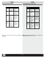
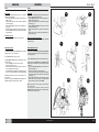
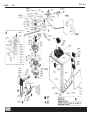
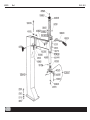
ES
D
TIRE CHANGING MACHINE
DESMONTA-NEUMATICOS
320 S - 326 S
COD.103932
Rev.1
INSTRUCTIONS MANUAL
MANUAL DE INSTRUCCIONES
EN
ENGLISH
ESPAÑOL
WARNINGS
ADVERTENCIAS
The present instructions booklet is an integral part of the product. Carefully study the warnings and instructions contained in it. This information is
important for safe use and maintenance. Conserve this booklet carefully for further consultation.
El presente manual de instrucciones forma parte integrante del producto. Leer atentamente las advertencias y las instrucciones que se señalan en el
mismo, ya que suministran indicaciones importantes referentes a la seguridad del uso y mantenimiento. Conservar con cuidado este manual para
ulteriores consultas.
320 S - 326 S IS AN AUTOMATIC TIRE CHANGING MACHINE DESIGNED AND CONSTRUCTED TO BE USED FOR THE MOUNTING AND DEMOUNTING OF TIRES FOR CARS AND MOTORCYCLES.
THE MACHINE HAS BEEN DESIGNED TO OPERATE WITHIN THE LIMITS DESCRIBED IN THIS BOOKLET AND IN ACCORDANCE WITH THE
MAKER’S INSTRUCTIONS.
The machine must be used only for the purpose for which it was expressly designed. Any other use is considered wrong and therefore unacceptable.
The manufacturer cannot be held responsible for damage resulting from improper, erroneous, or unacceptable use of the machine.
320 S - 326 S ES UN DESMONTA-NEUMATICOS AUTOMATICO PROYECTADO Y CONSTRUIDO PARA SER UTILIZADO COMO HERRAMIENTA
PARA EL DESMONTAJE Y EL MONTAJE DE LOS NEUMATICOS SOBRE LLANTAS DE RUEDAS DE TURISMOS Y DE MOTOCICLETAS.
LA MAQUINA HA SIDO IDEADA PARA FUNCIONAR DENTRO DE LOS LIMITES INDICADOS EN EL PRESENTE MANUAL DE USO Y EN CONFORMIDAD
A LAS INSTRUCCIONES DEL CONSTRUCTOR.
La máquina debe contemplar un uso adecuado únicamente a su ideación. Cualquier otro tipo de uso está considerado como impropio y por lo tanto
irrazonable.
No se ha de considerar responsable al constructor si la máquina sufrirá daños causados por un uso inadecuado y erróneo.
This symbol is used in the present manual to warn the operator of particular risks associated with the use of the machine.
Este símbolo se utiliza en el presente manual cuando se desea llamar la atención del operador sobre particulares riesgos relacionados con el
uso de la máquina.
CONTENTS
ÍNDICE
GENERAL WARNING .......................................................................................................................................................................................................... 2
ADVERTENCIAS GENERALES .......................................................................................................................................................................................... 2
TECHNICAL CHARACTERISTICS .................................................................................................................................................................................... 3
CARACTERISTICAS TECNICAS ........................................................................................................................................................................................ 3
COMPONENT PARTS ........................................................................................................................................................................................................ 4
DESCRIPCION DE LA MAQUINA ....................................................................................................................................................................................... 4
ACCESSORIES
- Accessories provided ........................................................................................................................................................................................................ 5
- Accessories on request .................................................................................................................................................................................................... 6
DESCRIPCION DE LAS PIEZAS COMPONENTES
- Accesorios de equipo ......................................................................................................................................................................................................... 5
- Accesorios opcionales ...................................................................................................................................................................................................... 6
UNPACKING AND LOCATION ............................................................................................................................................................................................ 7
DESEMBALAJE Y COLOCACION ..................................................................................................................................................................................... 7
INSTALLATION
- Assembly procedures ........................................................................................................................................................................................................ 8
- Pneumatic and electrical connection .............................................................................................................................................................................. 9
- Malfunctions: causes and possible remedies ............................................................................................................................................................... 10
INSTALACION
- Operaciones de montaje .................................................................................................................................................................................................... 8
- Conexión neumatica y eléctrica ....................................................................................................................................................................................... 9
- Mal funcionamiento, su causa y posible remedio ......................................................................................................................................................... 10
INSTRUCTIONS FOR USE
- Tire bead breaking and unmounting operations ............................................................................................................................................................ 11
- Mounting and inflation operations .................................................................................................................................................................................. 12
INSTRUCCIONES PARA EL USO
- Operaciones de destalonamiento y desmontaje del neumático .................................................................................................................................... 11
- Operaciones de montaje y de hinchamiento del neumático ......................................................................................................................................... 12
320 S .................................................................................................................................................................................................................................. 13
320 S .................................................................................................................................................................................................................................. 13
326 S .................................................................................................................................................................................................................................. 15
326 S .................................................................................................................................................................................................................................. 15
ROUTINE MAINTENANCE ............................................................................................................................................................................................... 16
MANTENIMIENTO RUTINARIO ........................................................................................................................................................................................ 15
MOVEMENT AND STORAGE ......................................................................................................................................................................................... 16
INSTRUCCIONES PARA MOVER Y ARRINCONAMIENTO .......................................................................................................................................... 16
TECHNICAL ASSISTANCE AND SPARE PARTS ........................................................................................................................................................... 17
ASISTENCIA TECNICA Y PIEZAS DE REPUESTO ...................................................................................................................................................... 16
COD. 103932 Rev.1
2
ENGLISH
ESPAÑOL
TECHNICAL CHARACTERISTICS
CARACTERISTICAS TECNICAS
TECHNICAL DATA
DATOS TECNICOS
320 S - 326 S
320 S
326 S
DIMENSIONS
Max. height ........................................... 69" .................................. 74"
Depth .................................................... 44" .................................. 40"
Width ..................................................... 30" .................................. 30"
320 S
326 S
DIMENSIONES
Altura máx ............................................. 69" .................................. 74"
Profundidad .......................................... 44" .................................. 40"
Anchura ................................................. 30" .................................. 30"
WEIGHT
Net weight ....................................... 452 lb. ............................ 481 lb.
Gross weight ................................... 518 lb. ............................ 540 lb.
PESO
Peso Neto ........................................ 452 lb. ............................ 481 lb.
Peso Bruto ....................................... 518 lb. ............................ 540 lb.
ELECTRIC MOTOR
Power .................................................. 1 Hp
Phases .................................................. 1 ~
Voltage ............................................. 110 V
Bead breaker force ....................... 5.500 lb.
MOTOR ELECTRICO
Potencia .............................................. 1 Hp
Fases .................................................... 1 ~
Alimentación .................................... 110 V
Fuerza Destalonador ................... 5.500 lb.
................................ 1 Hp
................................... 1 ~
............................. 110 V
......................... 5.500 lb.
................................ 1 Hp
................................... 1 ~
............................. 110 V
......................... 5.500 lb.
NOISE LEVEL .................................. 75 db .............................. 75 db
RUIDOSIDAD .................................... 75 db .............................. 75 db
PNEUMATIC SUPPLY
Min./max. operating pressure ........................................... 110-170 psi
ALIMENTACION NEUMATICA
Presión de trabajo mín/máx .............................................. 110-170 psi
RANGE OF APPLICATIONS
GAMA DE APLICACIONES
320 S - 326 S can operate on wheels having the following minimum and
maximum dimensions:
320 S
326 S
VEHICLE WHEEL
min/max
min/max
Wheel width ................................................... 3"-10" ............... 3"-12"
Max. wheel diameter .......................................... 40" .................... 44"
Rim diameter (locked internally) ................. 12"-23" ............. 12"-28"
Rim diameter (locked externally) ............... 10"-20" ............. 10"-26"
320 S - 326 S puede obrar sobre ruedas y llantas con las dimensiones
mínimas y máximas siguientes:
320 S
326 S
VEHICLE WHEEL
mín/máx
mín/máx
Anchura rueda ............................................... 3"-10" ............... 3"-12"
Diámetro máx. rueda .......................................... 40" .................... 44"
Diámetro llanta (bloqueo int) ....................... 12"-23" ............. 12"-28"
Diámetro llanta (bloqueo ext) ..................... 10"-20" ............. 10"-26"
MOTORCYCLE WHEEL *
min/max
min/max
Wheel width ................................................... 3"-10" ............... 3"-10"
Max. wheel diameter .......................................... 40" .................... 44"
Rim diameter ................................................ 15"-25" ............. 15"-25"
RUEDAS MOTOCICLETAS*
mín/máx
mín/máx
Anchura rueda ................................................ 3"-10" ............... 3"-10"
Diámetro máx. rueda .......................................... 40" .................... 44"
Diámetro llanta ............................................. 15"-25" ............. 15"-25"
In order to work on motorcycle wheels it is necessary to install the
motorcycle attachments, available on request (see pg.6).
* Para obrar sobre ruedas de motocicletas es necesario instalar el
dispositivo “conexión motocicletas”, disponible a pedido (v.pág.6)
REGISTRATION PLATE DATA
DATOS DE CHAPA
THE MACHINE DATA IS ON A SPECIAL LABEL ON THE BACK OF THE
MACHINE.
LOS DATOS DE LA MÁQUINA SE ENCUENTRAN EN LA ETIQUETA
INDELEBLE SITUADA EN LA PARTE TRASERA DE LA MÁQUINA.
This contains the specifications, the CE mark, the year of construction
and the serial number.
En la misma se señalan los datos técnicos, la marca CE, el año de
construcción y el número de matrícula.
The Serial number must be quoted in the communications with technical
assistance.
El Número de matrícula debe ser citado en las comunicaciones con la
asistencia técnica
COD. 103932 Rev.1
REGISTRATION PLATE DATA
DATOS DE CHAPA
3
ENGLISH
ESPAÑOL
320 S - 326 S
DESCRIPTION OF THE MACHINE
DESCRIPCION DE LA MAQUINA
with illustrations of the component parts relevant for use
con ilustraciones de las piezas componentes importantes para el
uso
PEDAL CONTROLS (fig. 1)(1)
The machine control pedals include:
» Switch control pedal (1-A) is on both sides of the machine and
rotates the chuck plate in the direction desired;
» Bead breaking control pedal (1-B) to activate the bead breaking
arm (2-F)
» Open control pedal (1-C) for opening and closing the chuck jaws (4P)
» Close control inflation for seating bead and inflating tire (1-D)
for closing the chuck bead seating and inflating the tire (4-P)
BEAD BREAKER (fig. 1) (2)
The bead breaker is a mechanism for unbeading tires from rims and is
composed of:
» Bead breaking arm (2-F) activated pneumatically by a double action
cylinder
» Plate (2-E) for tire bead breaking
» Anti-abrasion supports (2-G) for support during the bead breaking
phase.
COLUMN UNIT (Fig.1) (3)
The column unit is composed of a fixed column which can be tilted back
and which carries the components necessary for unmoun-ting the tire from
the rim (and for re-mounting)
» the swinging arm (3-H) for positioning the head.
» the handwheel (3M) for the adjustment of the horizontal position of
the arm:
» locking lever (3-L) for regulating the vertical position of the rod
» the head (3-I) for removing (and refitting) the tire from the rim with the
help of the bead lifting lever (see accessories provided).
» the sliding roller (3-N), inserted inside the tongue of the head, avoids
any damage to the rim or bead.
SELF-CENTERING CHUCK (Fig.1) (4)
The chuck is the device for locking and rotating the rim. It is driven pneumatically two self-centring cylinders and is composed of:
» 4 slide tracks (4-P) with 4 locking wedges (4-O) for the internal and
external locking of the rim
» A self-centring plate (4-Q) for rotating the rim in both directions without unlocking it.
KEY
JUEGO DE PEDALES (fig.1) (1)
Incluye los pedales de mando de la máquina:
» Pedal mando invertidor (1-A) presente en los dos lados de la máquina,
para hacer girar el plato autocentrado en el sentido deseado.
» Pedal mando destalonador (1-B) para accionar el brazo destalonador
(2-F).
» Pedal mando abertura (1-C) para abrir y cerrar las mordazas del
Autocentrado (4-P)
» Pedal mando cierre (1-D) para cerrar las mordazas del Autocentrado
(4-P).
1
DESTALONADOR (fig.1) (2)
El Destalonador es el dispositivo para destalonar el neumático de la llanta
e incluye:
» Brazo Destalonador (2-F) accionado neumá-ticamente por un cilindro
de doble efecto.
» Paleta (2-E) para el destalonamiento del neumático.
» Apoyos antiabrasivos (2-G) para apoyar la llanta durante la fase de
destalonamiento.
UNIDAD COLUMNA (fig.1) (3)
La Unidad Columna se compone de una Columna fija que soporta los
componentes necesarios para desmontar el neumático de la llanta (y para
montarlo nuevamente):
» el brazo oscilante (3-H) para la colocación de la Torre;
» la manivela (3M) para el arreglo de la posición horizontal del brazo;
» la palanca de bloqueo (3-L) para ajustar la posición vertical de la
barra.
» la torre (3- I) para quitar el neumático de la llanta (y para montarlo
nueva-mente) con el auxilio de la palanca levanta-talones (vea
accesorios de equipo);
» el rodillo de deslizamiento (3-N) insertado en la lengüeta de la Torre,
permite actuar sobre el neumático sin dañar llanta y talón.
AUTOCENTRADO (fig.1) (4)
El Autocentrado es el dispositivo para el bloqueo y la rotación de la llanta;
se acciona neumáticamente gracias a dos cilindros autocentrados y se
compone de:
» 4 recorridos móviles (4-P) con cuñas de bloqueo (4-O) para el
bloqueo interior y exterior de la llanta.
» un plato autocentrado (4-Q) para girar la llanta en los dos sentidos
sin desbloquearla..
EXPLICACION
1) PEDALS
A: Switch pedal
B: Bead-breaker pedal
C: Open pedal
D: Inflation pedal
3) COLUMN
H: Swinging arm
I: Head
L: Locking lever
M: Handwheel
N: Sliding roller
1) JUEGO DE PEDALES
A: Pedal Invertidor
B: Pedal Destalonador
C: Pedal Abertura
D: Pedal Cierre
3) COLUMNA
H: Brazo oscilante
I: Torre
L : Palanca de Bloqueo
M: Manivela
N: Rodillo de deslizamiento
2) BEAD-BREAKER
E: Bead-breaking plate
F: Bead-breaking arm
G: Anti-abrasion supports
4) SELF-C.CHUCK
O: Locking wedges
P: Slide tracks
Q: Self-centring plates
2) DESTALONADOR
E: Paleta Destalonador
F: Brazo Destalonador
G: Apoyos antiabrasivos
4) AUTOCENTRADO
O: Cuñas de Bloqueo
P: Recorridos móviles
Q: Plato Autocentrado
COD. 103932 Rev.0
4
ENGLISH
ESPAÑOL
320 S - 326 S
ACCESSORIES PROVIDED
ACCESORIOS DE EQUIPO
BEAD LIFTING LEVER (fig. 2)
This is a tool required for lifting the tire bead onto the head during the
unmounting stage (see fig. 2 and instructions page 11 and 12).
It also allows the guiding of the bead “setting” during mounting.
When the machine has been installed the bead lifting lever is kept in the
container in the bead breaking machine case on the side of the machine.
PALANCA LEVANTA-TALON (fig.2)
Es una herramienta necesaria para levantar el talón del neumático y llevarlo
sobre la torre durante las fases de desmontaje (véase fig. 2 e instrucciones
de pág. 11 y 12).
Consiente luego de guiar el “encauzamiento” del talón mismo en la fase
de montaje del neumático. La palanca levanta-talones, una vez instalada
la máquina, debe colocarse en la ranura del apoyo del destalonador, al
lado de la máquina.
LUBRICATION PAIL RING (fig.3)
This ring holds the lubrication pail used during mounting and demounting
of tires. Once the machine has been installed the lubrication pail is fitted
in the position indicated in fig.3.
A brush is also provided for lubricating the bead.
2
3
ANILLO PORTA-TARRO (fig.3)
Sirve de soporte al tarro de la grasa que se debe utilizar durante la fase de
montaje de los neumáticos. Después de la instalación de la máquina, el
anillo debe fijarse a la columna como muestra la fig. 3.
Además, está suministrado un pincel para engrasar el talón del neumático.
The box containing the accessories provided (Fig. 4) is placed in the
machine packing materials (See unpacking instructions on page 7).
La caja que contiene los accesorios de equipo (fig. 4) está en el
embalaje de la máquina (véase instrucciones para desembalar a pág. 7)
Always pay careful attention to the WARNING SIGNS shown on
decals applied to the machine (fig.5).
Tenga siempre mucho cuidado con las SEÑALES DE
SEGURIDAD representadas con adhesivos adecuados y
aplicados en la máquina (fig. 5).
If one or more of the warning signs disappears or shows signs of deterioration, you are requested to order a replacement from ACCU-TURN’s “Spare
Parts” service, making use of the relevant code number:
En caso de pérdida o deterioro de una o más etiquetas adhesivas
aplicadas en la máquina, dirígase inmedia-ta-mente al servicio”piezas
de repuesto” ACCU-TURN para requerirla/las indicando el número de
código relativo:
4
5
(a) -”head” decal (code no. 100982 )
(a) - etiqueta “torre” (cód. n. 100982)
(b) - “electrical tension” decal (code no. 100789)
(b) - etiqueta “tensión” (cód. n. 100789)
(c) - “bead-breaker” decal (code no.100983)
(c) - etiqueta “destalonador” (cód.n.100983)
COD. 103932 Rev.1
5
ENGLISH
ESPAÑOL
320 S - 326 S
ACCESSORIES ON REQUEST
ACCESORIOS OPCIONALES
FILTER UNIT FR + L (fig. 6)
This unit is composed of a Filter to eliminate possible impurities and
excessive humidity in the air, a Pressure Reducer to maintain the correct
operating pressure, and a Lubricator to atomize oil in the pneumatic system.
UNIDAD FILTRO FR + L (fig. 6)
La Unidad se compone de un Filtro para eliminar las eventuales
contaminaciones y la excesiva humedad presente en el aire, de un
Reductor de presión para el correcto ajuste de la presión de trabajo y de
un Lubrificador para pulverizar aceite en la instalación neumátic.
ALLOY RIM PROTECTORS
These are special protectors designed for use on light alloy rims: ¬ 19"
Locking wedge protectors. (fig.7) - 4p. - Mount/demount head protectors
(fig. 8) - 1p.
PROTECCIONES PARA LLANTAS DE ALEACION.
Son especiales protecciones predispuestas para actuar sobre llantas de
aleación ligera: ¬ Protecciones recorridos para cuñas de 19" (fig. 7) - 4p.
- Protección Lengüeta de la torre (fig. 8) - 1p.
The inflation of tires is a potentially dangerous operation!
For the inflation of tires on the chuck plate in conditions of
maximum safety, it is advisable to order, fit and use the special
SAFETY BELTS. (see fig. 10 and pg. 11 and 12)
El hinchamiento del neumatico es una operacion
potencialmente peligrosa!
Para hinchar el neumatico sobre el plato del autocentrado
en condiciones de seguridad es obligatorio utilizar los
apropiados CINTURONES DE SEGURIDAD (fig. 10 y pag. 11 y
12)
8" FITTINGS WHEEL CLAMP (4 p.)
these allow the unmounting of tires on small wheels (e.g. tires from trolleys, garden equip., golf carts, etc.(fig. 11).
DISPOSITIVO “CONEXIONES 8”(4p.)
permite el desmontaje de los neumáticos de pequeñas dimensiones como
por ejemplo los neumáticos de carretillas, de herramientas para el jardín,
de medios móviles para el golf, etc. (v.fig.11).
17.5" SPECIAL FITTINGS WHEEL CLAMP (4p.)
these allow work on special 17.5" wheels with an external rim flange that
extends beyond the edge of the rim (see fig. 12).
MOTORCYCLE FITTINGS WHEEL CLAMP
This is an attachment that allows the mounting and unmounting tires from
motorcycle wheels from 15" to 24" (fig. 13). A polyurethane coating protects the rims from marking. The “motorcycle attachment” parts (series of
4 parts) are easily mounted: they are simply inserted in the tracks of the
chuck and locked with the bolt provided.
6
7
8
10
DISPOSITIVO “CONEXIONES ESPECIALES 17,5” (4p.)
sirve para obrar sobre llantas parti-culares de 17,5" con brida exterior más
saliente con respecto al borde de la llanta (fig. 12).
DISPOSITIVO “CONEXIONES MOTOS”
es un dispositivo que consiente desmontar y montar los neumáticos de
las ruedas de motocicletas de 15" a 24" (fig. 13). Una capa de poliuretano
protege de eventuales rayas la llanta misma. Las “conexiones motos”
(serie de 4 p.) se montan con facilidad: basta con introducirlas en los
recorridos del autocentrado y bloquearlas con los tornillos apropiados.
13
12
11
COD. 103932 Rev.0
6
ENGLISH
ESPAÑOL
320 S - 326 S
UNPACKING
DESEMBALAJE
On receipt of the packed machine, remove the straps (taking care when
cutting them) and packing as in fig. 14. After removing the packing check
the machine for missing or damaged parts. If in doubt do not use the
machine and refer to professionally qualified personnel and/or to the
seller.
Al recibir la máquina embalada, quite los flejes, (poniendo mucho cuidado
con quitarlos), los sellos y el cartón como muestra la fig.14. Después de
haber quitado el embalaje, asegúrese de que la máquina esté íntegra
controlando si hay algún daño en sus piezas componentes. En caso de
duda no utilice la máquina, sino dirígase inmediatamente al personal
profesionalmente cualificado y/o a su mismo revendedor.
The packing materials (timber, plastic bags, pluriball, polythene,
nails, staples, etc.) must not be left within reach of children since
they are potentially dangerous.
Deposit the above mentioned materials at the relevant collection
points if they are pollutants or are non biodegradable.
14
Los elementos del embalaje (cartón, sellos y flejes) no deben estar
al alcance de los niños porque son fuentes de potencial peligro.
Ponga dicho material, si contaminador y no biodegradable, en los
apropiados sitios de recogida.
LOCATION
COLOCACION
OVERALL DIMENSIONS:
68.5" x 37" x 33"
DIMENSIONES MAXIMAS EXTREMAS:
68.5" x 37" x 33"
SAFE DISTANCE
For the safe and ergonomic use of the machine, it is advisable to locate
it a minimum of 20" from the surrounding walls.
DISTANCIAS DE SEGURIDAD
Para una utilización segura y ergonómica de la máquina se aconseja
colocarla a una distancia mínima de 20" de las paredes cercanas.
FIXING REQUIREMENTS
The machine is fitted with special rubber feet for the muffling of possible
vibrations.
PRESCRIPCIONES DE FIJACION
La máquina está equipada con especiales tapones de goma para amortiguar
las vibraciones.
To inflate tires on the chuck plate it is necessary to mount the machine to the floor.
For this purpose use the same holes provided for mounting the machine to the pallet (fig. 20, pg. 8).
Para poder hinchar el neumático sobre el plato del autocentrado es
obligatorio fijar en tierra la máquina.
Para esta operación utilice los mismos orificios utilizados para fijar
la máquina sobre el palet. (fig. 20 pag. 8)
THE MACHINE MUST NOT BE LOCATED IN AN EXPLOSIVE ENVIRONMENT.
NUNCA COLOCAR LA MAQUINA EN AMBIENTE EXPLOSIVO.
COD. 103932 Rev.1
15
7
ENGLISH
ESPAÑOL
320 S - 326 S
INSTALLATION
INSTALACION
Assembly operations and locating the machine
Operaciones de montaje y colocación de la máquina
REMOVING THE COVER
» Remove the 4 side cover screw with a 0.4" spanner (fig. 16); Remove
the side cover
DESMONTAJE DE LA TAPA
» Quite los 4 tornillos de la tapa lateral con una llave de 0.4". (fig. 16);
Desmonte la tapa lateral
RAISING THE COLUMN
» Make use of a 3 ft. hoisting strap model DR 50 - safety factor 6:1. Wrap
the strap around the movable arm (fig. 17a)
» Open the bead breaking arm as shown in fig. 17b (1) and raise the
column with a hoist (2).
» Rest the column on the machine body.
LEVANTAMIENTO DE LA COLUMNA
» Procúrese una correa de levanta-miento de m. 1 modelo DR 50 - factor
de seguridad 6:1. Arrolle la correa al brazo oscilante (fig. 17a).
» Abra el brazo destalonador como muestra la fig. 17b (1) y levante la
columna con un gato (fig.17b) (2).
» Apoye la columna sobre la caja.
ATTACHING THE COLUMN
» Attach the column to the machine body (fig. 18) using the screws
contained in the accessories box:
- 4 TEM10 screws
- 4 M10 hex. nuts
- 4 chamfered washers diam.10
- 4 split washers diam.10
FIJACION DE LA COLUMNA
» Fije la columna a la caja (fig. 18), con los tornillos contenidos en la
caja de los accessorios de equipamiento.
- 4 tornillos TEM10
- 4 tuercas M10 hex.
- 4 arandelas achaflanadas diam.10
- 4 arandelas hendidas diam.10
SETTING THE SPRING ON THE VERTICAL ROD
» Release the vertical rod, lift it up 4" and lock it again as shown in
fig.19a (1).
» Unscrew the cap at the top of the rod with a 6 mm hex key (fig.19a)
(2).Warning: when unscrewing the rod take the precaution of keeping
one hand underneath it (fig.19b) (1) and (2).
» Remove the rod. Slide the spring off and re-insert the rod (fig.19c)(1) in
its original seating, locking it at the end of its travel (fig. 19c) (2).
» Insert the spring on the top of the rod (fig.19c) (3) and refit the cap with
a 0.25" hex key.
COLOCACION DEL RESORTE DE LA BARRA VERTICAL
» Desbloquear la barra vertical levantarla de 4" y volver a bloquearla
nuevamente como muestra la fig. 19a (1).
» Destornille la cápsula colocada encima de la barra con una llave de
allen de 6 mm. (fig. 19a)(2). Atención:desbloque la barra metien-do
una mano debajo de la barra misma (v. fig. 19b) (1) y (2).
» Extraiga la barra. Extraiga el resorte e introduzca nuevamente la barra
(fig.19c) (1) en su asiento originario, bloqueándola al tope del recorrido
(fig. 19c) (2).
» Introduzca el resorte en la parte superior de la barra (fig.19c) (3) y
atornille nueva-mente la cápsula con la llave de allen de 0.25".
WARNING: when installing the machine make sure that the nut is
correctly fastened in the cylinder rod as shown in the figure – an
incorrect mounting compromises the functioning and represents a
danger for the operator. (fig.20)
ATENCIÓN: durante la instalación de la máquina, asegúrese de que
la tuerca esté correctamente atornillada al vástago del cilindro como
se indica en la figura. Un montaje incorrecto es perjudicial para el
funcionamiento y representa un peligro para el operador.(fig. 20)
POSITIONING THE MACHINE
» Refit the side cover (fig.16) with the 4 TEM6 flanged self-threading
crews with a 0.4" spanner.
» Unscrew the two bolts that fix the machine to the pallet (fig.20a).
» Wrap the lifting strap (a) (mod. DR250 of 3 ft.) around the column
and strap (b) (mod. FA650 of 10 ft.) (fig. 20b).
» Pass strap (b) through the holes in the flange.
Warning: take care not to crush the cylinder supply tubes !.
» Thread strap (b) through the loop of strap (a); raise the machine with a
hoist (fig. 20b).
» Remove the pallet and position the machine.
COLOCACION DE LA MAQUINA
» Monte nuevamente la tapa lateral (fig. 16) aplicando los 4 tornillos
TEM6 rebordeados y autoenroscantes con una llave de 0.4".
» Destornille las 2 tuercas que fijan la máquina sobre el palet (fig. 20a).
» Enrolle la correa (a) de levantamiento (mod. DR250 de 3 ft.) a la columna y a la correa (b) (mod. FA650 de 10 ft.) (fig. 20b).
» Haga pasar la correa (b) por las ranuras de la brida.
Atención: ctúe con cuidado para no apretar los tubos de alimentación
de los cilindros.
» Inserte la correa (b) en el nudo de la correa (a); levante la máquina con
el gato (fig. 20b).
» Quite el palet y coloque la máquina.
16
COD. 103932 Rev.0
17a
19b
19a
18
20
17b
20a
19c
20b
8
ENGLISH
ESPAÑOL
320 S - 326 S
INSTALLATION
INSTALACION
Connection and operation checks
Conexiones y pruebas de funcionamiento
PNEUMATIC CONNECTION
» Connect the compressed air to the connector positioned between the
lubricator and the air filter (2, fig. 21).
CONEXION NEUMATICA
» Conecte la toma del aire comprimido a la unión colocada entre el
lubrificador y el filtro del aire (vea fig. 21) (2).
ELECTRICAL CONNECTION
CONEXION ELECTRICA
ALL WORK ON THE ELECTRICAL SYSTEM, INCLUDING MINOR
OPERATIONS, MUST BE CARRIED OUT BY PROFESSIONALLY
QUALIFIED PERSONNEL !
CADA INTERVENCION SOBRE EL SISTEMA ELECTRICO,
INCLUSO DE LEVE ENTIDAD, DEBE EFECTUARSE POR EL
PERSONAL PROFESIONALMENTE CUALIFICADO!
» Check that the mains supply voltage is the same as that shown on the
» Controle la conformidad entre la tensión de línea y aquella indicada
registration plate (as shown in fig. 22).
» Check that the ground connection is effective.
» The machine must be connected to the mains through a multipolar
isolating switch which conforms with European norms and with contact openings of at least 0.1".
sobre la chapa de la máquina (como indica la fig. 22).
» Compruebe la eficacia de la toma de tierra.
» La máquina debe estar conectada a la red mediante un selector
omnipolar conforme a las normativas europeas, con abertura de los
contactos de 0.1" al menos.
THE MANUFACTURER DOES NOT ACCEPT ANY RESPONSIBILITY
FOR THE FAILURE TO OBSERVE THE ABOVE MENTIONED INSTRUCTIONS.
EL CONSTRUCTOR DECLINA TODA RESPONSABILIDAD PARA UNA
ERRADA OBSERVANCIA DE DICHAS PRESCRIPCIONES.
OPERATIONAL CHECK (see fig. 23):
PRUEBAS DE FUNCIONAMIENTO(véase la fig. 23):
it is very important for the correct functioning of the machine that a
downward pressure on the switch pedal (A) produces a clockwise
rotation of the chuck plate.
22
21
Es muy importante para un funcionamiento correcto de la máquina
que al apretar el pedal del invertidor (A) hacia abajo se corresponda
un movimiento rotatorio del autocentrado en sentido horario.
COD. 103932 Rev.1
23
9
ENGLISH
ESPAÑOL
MALFUNCTIONS: CAUSES AND POSSIBLE REMEDIES
Malfunction
The chuck does not
rotate
in
any
direction
The chuck rotates
only weakly.
The chuck does not
lock the wheel
correctly.
1.
2.
3.
1.
2.
1.
2.
3.
The bead-breaker
does not have
sufficient power to
break the bead.
1.
2.
3.
Cause
Electrical supply not plugged
in.
Incorrect plug connection.
Electrical tension is incorrect
Incorrect mains tension.
Loose drive belt
The pneumatic supply has
not been connected to the
machine.
Pneumatic supply pressure
too low.
Pressure reducer closed or
badly adjusted (for the
versions with this device)
The pneumatic supply has
not been connected to the
machine.
Pneumatic supply pressure
too low.
Pressure reducer closed or
badly adjusted (for the
versions with this device)
MALOS FUNCIONAMIENTOS, CAUSAS Y REMEDIOS POSIBLES
1.
2/3
1.
2.
1.
2.
3.
1.
2.
3.
Malos
funcionamientos
El autocentrado no
gira en ningún
sentido
Possibile remedies
Check the correct insertion
of the plug and its
connections.
(see 1)
Check the correspondence
of the mains tension with
that shown on the reg. plate
of the machine.
Adjust the belt tightener
Connect the pneumatic
system.
Increase the pressure.
Activate or correct the
adjustment of the pressure
reducer
El autocentrado gira
con fuerza
insuficiente
Causas
1.
2.
3.
1.
2.
Enchufe de tensión
Errada conexión del enchufe
mismo
Tensión no conforme
Errada tensión de red
Correa floja
Remedio posibles
1.
2-3
1.
2.
El autocentrado no
bloquea
correctamente la
rueda
1.
2.
3.
Connect the pneumatic
system.
Increase the pressure.
Activate or correct the
adjustment of the pressure
reducer
El destalonador no
tiene fuerza
suficiente para
accionar la rueda
1.
2.
3.
Other possible malfunctions are principally technical in nature and must be checked and resolved by PROFESSIONALLY QUALIFIED TECHNICIANS.
La red neumática no ha sido
conectada a la máquina
Insuficiente presión a la red
neumática
Reductor de presión cerrado
o mal ajustado (para las
versiones con este
dispositivo)
La red neumática no ha sido
conectada a la máquina
Insuficiente presión a la red
neumática
Reductor de presión cerrado
o mal ajustado (para las
versiones con este
dispositivo)
1.
2.
3.
1.
2.
3.
Conecte correctamente el
enchufe con la toma de
corriente
(véase arriba el punto 1)
Verifique la correspondencia
entre la tensión de red y
aquella indicada sobre la
chapa del constructor
Actúe sobre el tensor de
correa
Conecte la red neumàtica
Ajuste apropiadamente la
presión de la red
Abra o ajuste correctamente
el reductor de presión
Conecte la red neumática
Ajuste apropiadamente la
presión de la red
Abra o ajuste correctamente
el reductor de presión
Otro eventual mal funcionamiento ha de considerarse de carácter únicamente técnico, por lo tanto es el PERSONAL CUALIFICADO
PROFESIONALMENTE que debe intervenir con controles y correcciones.
COD. 103932 Rev.1
10
ENGLISH
ESPAÑOL
320 S - 326 S
INSTRUCTIONS FOR USE
INSTRUCCIONES PARA EL USO
PRELIMINARY OPERATIONS
» Completely deflate the tire;
» Remove wheel balancing weights to eliminate any danger arising from
their presence.
OPERACIONES PRELIMINARES
» Deshinche por completo el neumático;
» Quite los pesos de equilibración de la rueda para eliminar todo riesgo
procedente de la presencia de los pesos mismos.
BEAD-BREAKING (fig. 24)
» Place the wheel on the ground near the bead-breaker. Move the plate
(E) towards the bead and press the bead-breaking control pedal (B).
This operation is conducted at various points of the wheel until the
bead is completely detached.
» Repeat the operation on the opposite side of the wheel.
DESTALONAMIENTO (fig. 24)
» Ponga en tierra la rueda al lado del destalonador; acerque la paleta (E)
al talón y apriete el pedal mando del destalonador (B). La operación
debe realizarse en varios puntos de la rueda hasta que el talón no esté
completamente separado.
» Repita la operación sobre el lado opuesto de la rueda
WHEN USING THE BEAD-BREAKING ARM TAKE CARE NOT TO
TRAP LIMBS BETWEEN THE TIRE AND THE BEAD-BREAKER!
DURANTE EL ACCIONAMIENTO DEL BRAZO DESTALONADOR,
TENGA MUCHO CUIDADO PARA NO APLASTARSE LOS
MIEMBROS ENTRE EL NEUMÁTICO Y EL DESTALONADOR
MISMO!
DEMOUNTING (fig.25)
» Lower the locking lever (L) to unlock the vertical rod
» Press the open control pedal (C) to prepare the chuck jaws (O) to lock
the rim externally (in the case of internal locking, this operation is not
carried out).
» Place the wheel on the self-centring chuck, pressing lightly on the
wheel. Press the close control pedal (D) to lock it;
» Lubricate the bead with the brush specially provided (see box of accessories)
» Move the head (I) close to the rim so that the roller (N) and the rim edge
surface touch
» Raise lever (H): in this way the vertical spacing of the head and locking of the arm; the spacing of the tongue is adjusted by acting on the
handwheel M (3 mm ideal distance:).
» Raise the bead with the special lever (fig. 26) and hook it onto the
tongue of the mount/demount head (I)
» Rotate the chuck pressing the pedal (A) until the bead is completely
out of the rim.
DESMONTAJE (fig. 25)
» Baje la palanca de desbloqueo (L) y desbloque la barra vertical.
» Apriete el pedal mando de la abertura (C) para predisponer las mordazas
(O) para el bloqueo exterior de la llanta (en caso de bloqueo interior
esta operación debe evitarse).
» Ponga la rueda sobre el autocentrado actuando una leve presión sobre
la llanta; apriete el pedal mando del cierre
» (D) para bloquearla.
» Lubrifique el talón con la grasa utilizando el apropiado pincel de equipo
(vea la caja de los accesorios).
» Lleve la torre (I) acerca de la llanta y haga tocar el rodillo (N) y la
superficie con el borde.
» Levantar la palanca (H): de esta manera obtendrá la separación vertical de la torre y el bloqueo del brazo; actuando sobre el volante (M) se
ajusta la distancia de la lengüeta (medida óptima:3 mm).
» Levante el talón con la palanca apropiada (fig. 26) y póngalo sobre la
lengüeta de la torre (I).
» Gire el autocentrado apretando el pedal (A) hasta la completa salida
del talón de la llanta.
Take care not to insert fingers between tire and rim while the
chuck is rotating.
24
25
26
Actúe con cuidado evitando introducir los dedos entre
neumático y llanta, durante las fases de rotación del
autocentrado.
» Push the arm (H) aside and extract the inner tube.
» Repeat the same operation to remove the second bead.
» Aleje el brazo (H) de lado y extraiga la cámara neumática.
» Repita las mismas operaciones para la salida del segundo talón.
COD. 103932 Rev.1
11
ENGLISH
ESPAÑOL
320 S - 326 S
INSTRUCTIONS FOR USE
INSTRUCCIONES PARA EL USO
MOUNTING (see fig.27 and fig. 25)
» Lubricate the tire bead and place it on the rim; move the head to the
working position.
» Place the bead on the edge of the head (I) and under the tongue (fig. 27)
» Rotate the chuck by pressing pedal (A) taking care to make the bead
move into the central groove of the rim so as to eliminate weakening
the bead.
» (to help this action it is advisable to press down on the tire with the
hands).
» Move the adjstable arm (to free the work area)
» Place the rim with the inner tube valve at about 90° to the head, then
insert the inner tube
» Repeat the initial operation (see above) to locate the second bead.
» In the case that the bead has difficulty descending from the head, it
is necessary to “raise” (move upwards) the switch pedal (A) making the
chuck rotate in an counter-clockwise direction.
» Move the arm and press the open pedal (C) to unlock the rim
OPERACIONES DE MONTAJE (fig. 27 y 25)
» Lubrifique los talones del neumático y póngalo sobre la llanta;
» lleve la torre en posición de trabajo.
» Ponga el talón sobre el borde de la torre (I) y debajo de la lengüeta (fig.
27).
» Gire el autocentrado apretando el pedal (A) teniendo cuidado para
hacer entrar el talón en la ranura central de la
» llanta, con el fin de eliminar eventuales deformaciones del talón mismo
(para favorecer esta operación se aconseja presionar sobre el
neumático con ambas manos).
» Aleje el brazo (para liberar la zona de trabajo).
» Coloque la llanta con el orificio para la válvula de la cámara neumática
a 80° aprox. desde la torre; luego introduzca la cámara neumática.
» Repita las operaciones iniciales (vea arriba) para hacer entrar el
segundo talón. En el caso de que el segundo talón haga esfuerzo para
bajar de la torre, es necesario “levantar” (accione hacia arriba) el pedal
invertidor en sentido antihorario.
» Desplace el brazo apretando el pedal de abertura (C) para desbloquear
la llanta.
INFLATION PROCESS
OPERACIONES DE HINCHAMIENTO
WARNING !
The inflation process is potentially dangerous.
(see fig. 28/29)
The operator must adopt all the measures necessary in order to guarantee SAFE CONDITIONS
ATENCION !
La operación de hinchamiento es potencialmente peligrosa.
(véase Fig. 28-29).
El operador debe adoptar todas las medidas necesarias para
garantizar LAS CONDICIONES DE SEGURIDAD
INFLATION SAFETY DEVICE
The machine is fitted with a pressure limiting valve set at 3.5 bar and
a maximum pressure valve set at 4 bar. These are designed to protect
the operator from potential danger resulting from the inflation of tires on the
chuck plate.
DISPOSITIVO DE SEGURIDAD PARA EL HINCHAMIENTO
Para proteger al operador de los peligros que podrían proceder del
hinchamiento del neumático sobre el plato del autocentrado, la máquina
está dotada de una válvula limitadora de la presión de trabajo ajustada
a 3,5 bar y de una válvula de presión máxima ajustada a 4 bar.
WARNING !
To inflate tires on the chuck plate in conditions of “MAXIMUM
SAFETY” it is advisable to order, install and use the special
SAFETY BELTS
(see fig.10 on pg 6 and pgs 13 and 14)
ATENCION !
Para hinchar el neumático sobre el plato del autocentrado
en CONDICIONES DE SEGURIDAD es necesario requerir,
instalar y aplicar los apropiados CINTURONES DE SEGURIDAD
(véase fig. 10 en la pág. 6 y las páginas 13 y 14)
COD. 103932 Rev.0
27
28
29
12
ENGLISH
ESPAÑOL
320 S - 326 S
320 S
320 S
320 S is an automatic tire changer designed to operate also on tubeless
tires.
In addition to the basic model the machine is fitted with the following
components (see fig. 30):
» Automatic inflation device for tubeless tires (IT): This device has
a large capacity air circuit and an instantaneous valve. Activated with
the side inflation pedal (L) the air exits from two holes in each track.
These are ideally positioned to bead in tubeless tires.
» Compressed air cylinder conforming to EEC Directive 87/404. The
cylinder capacity means that the operator always has 4.5 gallons of
compressed air available for the inflation of tubeless tires (fig. 30-B).
» Inflation gauge: This is a gauge (fig. 30-C) fixed to the left side of the
column so as to allow the operator to support the tire during inflation.
The gauge conforms to EEC Directive 87/217.
320 S es un desmonta-neumáticos automático proyec-ta-do para obrar
también sobre los Neumáticos Tubeless.
Con respecto a la versión de base, la máquina está equipada con los
siguientes componentes (vea fig. 30):
» Dispositivo de hinchamiento auto-má-tico para neumáticos
Tubeless (IT): este dispositivo se caracteriza por un especial circuito
de aire “de grandes pasos” y por una válvula de abertura instantánea.
Accionando el pedal de hinchamiento (L) se produce una salida de
aire mediante dos orificios por cada recorrido, de manera que el
neumático Tubeless se pueda perfecta-mente talonar.
» Bombona de aire comprimido con-forme con lo establecido por la
Normativa 87/404 CEE: tiene un caudal que permite al operador de
tener siempre a disposi-ción 4.5 gallons de aire comprimido para el
hinchamiento de los neumáticos Tubeless (fig. 30-B).
» Manómetro de hinchamiento: se trata de un manómetro fijado sobre
el lado izquierdo de la columna (fig. 30-C) para permitir al operador de
sopor-tar el neumático durante las operaciones de hinchamiento. El
manó-metro cumple con las Normativas 87/217 CEE.
WARNING!
The inflation process is potentially dangerous !
The operator must adopt all the measures necessary in order to guarantee SAFE CONDITIONS.
30
ATENCIÓN!
La operación de hinchamiento es potencialmente peligrosa!
El operador debe adoptar todas las medidas necesarias para
garantizar LAS CONDICIONES DE SEGURIDAD.
SAFETY DEVICE
The machine is fitted with a pressure limiting valve set at 3.5 bar and a
maximum pressure valve set at 4 bar.
DISPOSITIVO DE SEGURIDAD
La máquina está dotada de una válvula limitadora de la presión de trabajo
ajustada a 3,5 bar y de una válvula de presión máxima ajustada a 4 bar.
ATENCIÓN !
Para hinchar el neumático sobre el plato del autocentrado
en condiciones de seguridad se aconseja aplicar los
CINTURONES DE SEGURIDAD.
(vea fig. 30a y figg. 35a-35b en la pág. 14)
WARNING!
For the inflation of tires on the chuck plate in conditions of
maximum safety, it is advisable to use the special SAFETY
BELTS
(see fig. 30a and fig. 35a-35b on pg. 14)
KEY
EXPLICACION
A:
B:
C:
D:
E:
F:
G:
H:
I:
A:
B:
C:
D:
E:
F:
LOCKING JAWS
SAFETY BELT (fig. 30a)
INFLATION GAUGE
AIR CYLINDER
SWITCH PEDAL
SPECIAL SLIDE TRACKS with holes for tubeless tires
BEAD BREAKING PEDAL
OPEN/CLOSE PEDAL
TUBELESS INFLATION PEDAL
30a
CUÑAS DE BLOQUEO
CINTURONES DE SEGURIDAD (fig. 30a)
MANOMETRO DE HINCHAMIENTO
BOMBONA DEL AIRE
PEDAL INVERTIDOR
RECORRIDOS MOVILES ESPECIALES CON ORIFICIOS PARA
TUBELESS
G: PEDAL DESTALONADOR
H: PEDAL ABERTURA Y CIERRE
I : PEDAL DE HINCHAMIENTO PARA TUBELESS
COD. 103932 Rev.1
13
ENGLISH
ESPAÑOL
320 S - 326 S
320 S
320 S
INSTALLATION
Refer to the general installation instructions on pgs. 12,14,16. In addition
follow the following instructions:
» Install the air cylinder behind the column using the two M8 bolts
supplied (fig. 31a);
» Connect the rubber hose to the cylinder connector and tighten the
connector band (fig. 31b).
» Connect the gauge holder to the column with the two M6 bolts supplied (fig. 32);
» Connect the air line hose to the connector on the filter unit (see fig. 33).
» Connect the small air hose to the quick connector, inserting it into the
relevant hole (fig. 34).
INSTALACION
Haga referencia a las modalidades generales de instalación de pág. 8-910. Además, siga las siguientes instruc-ciones:
» Instale la bombona del aire detrás de la columna aplicando los dos
tornillos de equipo de M8 (fig. 31a).
» Introduzca el tubo de goma en la unión de la bombona y apriete la
abrazadera. (fig. 31b).
» Conecte el soporte del manómetro a la columna con los dos tornillos de equipo de M6 (fig. 32).)
» Conecte el tubo del aire de línea con la unión de la unidad filtro (vea
fig. 33).
» Conecte el tubo del aire a la conexión rápida introduciéndolo en el
orificio apropiado (fig. 34).
Mounting the safety belts.
If there is a safety belt provided, install it as shown in figure 35.
Montaje de los cinturones de seguri-dad:
Si la máquina está dotada de los cinturones de seguridad, hay que instalarlos
según indica la fig. 35.
INSTRUCTIONS FOR USE
INSTRUCCIONES PARA EL USO
For bead-breaking, demounting and mounting tires, see the general
instructions on pgs. 11 and 12 of this manual.
Para las operaciones de Destalo-na-miento, Desmontaje y Montaje del
neu-má-tico haga referencia a las instruc-ciones generales de la pág. 11
y 12 del presente manual.
31a
31b
32
33
34
For the pedal controls refer to the key on pg. 26.
Para los mandos de pedal, haga referencia a la explicación de pág. 27.
For seating beads and inflation, after mounting the wheel on the rim
proceed as follows:
» If there is a safety belt, fit it as shown in fig. 30a on pg. 26.
» Attach the air hose to the tire valve;
» Raise the tire with both hands to allow the air (which comes out of the
tracks) to get between rim and tire (fig. 36);
» Press the inflation pedal (I) completely down to obtain the air output fro
the tracks. At the same time release the tire to allow the bead to set.
N.B.: Whenever the bead does not seat in, repeat all the stages in the
above sequence.
When the tire is seated, continue inflation by pressing the pedal in the
intermediate position until the desired pressure is reached.
Para las operaciones de talo-na-miento y de hinchamiento, después
de haber montado el neumático sobre la llanta, continúe siguiendo estas
indica-ciones:
» Aplique los cinturones de seguridad, si están en dotación, como
muestra la fig. (30a pág. 26).
» Introduzca el tubo del aire en la válvula del neumático;
» Levante el neumático hacia arriba con ambas manos, consentiendo al
aire (que sale por los orificios de los recorridos) de entrar entre llanta
y neumático (fig. 36);
» Apriete el pedal de hinchamiento (I) hasta el tope del recorrido, para
obtener la salida del aire de los recorridos y contemporáneamente
relaje el neumático para consentir su talo-namiento.
35
36
NOTA: Si el neumático ne se intalona, repita las operaciones descritas
arriba con más cuidado.
Cuando haya talonado el neumático, continúe la operación de
hinchamiento apretando el pedal apropiado (I) en la posición intermedia,
hasta el alcance de la presión deseada.
COD. 103932 Rev.0
14
ENGLISH
ESPAÑOL
320 S - 326 S
326 S
326 S
326 S (fig. 37) is a tire changing machine that combines the special features of the versions IT and AS, which are:
» Automatic system (IT) for the inflation of tubeless tires
activated with a special inflation pedal.
» Fixed column (A), a strong structure that allows work to be caried out
on wheels of large diameter (max diam. 44") (fig.37-F).
» Three-position Device (S) that allows the variation of the degree of
opening of the bead breaking plate (fig. 37-G).
326 S (fig. 37) es un desmonta-neumáticos que incluye los componentes
especiales de las versiones IT y AS, es decir:
» Dispositivo automático (IT) para el hinchamiento de los neumáticos
Tubeless, accionable mediante el apropiado pedal de hinchamiento.
» Columna Fija (A), cuya resistente estructura permite obrar sobre ruedas
de especial diàmetro (diàm. Màx 44") y anchura (ancho màax 16")
(fig.37-F)
» Dispositivo (S) a tres posiciones que permite variar la medida de
abertura de la paleta de destalonamiento (fig.37 -G).
The speciality of 326 S is the location of the air cylinder (or air bottle).
Unlike the IT version, the air cylinder is inside the fixed column
(v.Fig.37-F) and this create extra working space.
37
La peculiaridad del 326 S consiste en la especial colocaciòn de la
bombona del aire.
A diferencia de la versiòn IT, la bombona del aire està introducida
en la columna fija (véase fig. 37-F) a fin de ahorrar espacio en el sitio
de trabajo.
INSTALLATION
To connect the air cylinder fit the rubber hose to the junction on the cylinder
and tighten the metal strip as in fig. 37a.
INSTALACION
Para conectar la bombona del aire, inserte el tubo de goma en la unión del
tanque y apriete la abrazadera metálica como muestra la figura fig. 37a.
For other installation procedures refer to the general installation instructions on pgs. 7, 8, 9 and on pg. 13.
Para las posteriores modalidades de instalación, haga referencia a las
instrucciones generales de las páginas 7-8-9 y 13.
INSTRUCTIONS FOR USE
For the pedal controls refer to the key on pg. 13.
INSTRUCCIONES PARA EL USO
Para los mandos a pedal haga referencia a la leyenda de pág. 13. Para la
colocación de la paleta vea la página adyacente.
For the positioning of the bead breaking plate see previous page.
For the successive operations of bead-breaking, demounting and
mounting of the tire refer to the general instructions on pgs. 11 and 12 of
this manual.
For bead seating and inflation, follow the instructions and warnings on
pg. 14.
Para las operaciones de destalona-miento, montaje y desmontaje del
neumático haga referencia a las instruc-ciones generales y a las
advertencias de las páginas 11 y 12 del presente manual.
Para las operaciones de talona-miento y de hinchamiento, siga las
instrucciones y las advertencias de la pág. 14.
THE INFLATION PROCESS IS POTENTIALLY DANGEROUS.
The operator must adopt all the measures necessary in order to guarantee safe conditions
Whenever inflation is carried out on the chuck plate it is
necessary to use the special SAFETY BELTS
LA OPERACION DE HINCHAMIENTO ES POTENCIALMENTE
PELIGROSA.
El operador debe adoptar todas las medidas necesarias para
garantizar las CONDICIONES DE SEGURIDAD.
En particular, todas las veces que se efectúa el hinchamiento
del neumático sobre el plato del autocentrado, es obligatorio
aplicar los apropiados CINTURONES DE SEGURIDAD.
KEY
EXPLICACION
A:
B:
C:
D:
E:
F:
G:
H:
A:
B:
C:
D:
E:
F:
G:
H:
LOCKING JAWS
SAFETY BELT
INFLATION GAUGE
SWINGING ARM
WORK-HEAD ROD
COLUMN
BEAD BREAKER THREE-POSITION DEVICE
SP SLIDE TRACKS WITH TUBELESS HOLES
37a
CUÑAS DE BLOQUEO
CINTURONES DE SEGURIDAD
MANOMETRO DE HINCHAMIENTO
BRAZO OSCILANTE
BARRA PARA TORRE
COLUMNA
DISPOSITIVO A 3 POSICIONES
RECORRIDOS MOVILES CON ORIFICIOS ESPECIALES TUBELESS
COD. 103932 Rev.1
15
ENGLISH
ESPAÑOL
320 S - 326 S
ROUTINE MAINTENANCE
MANTENIMIENTO RUTINARIO
cleaning the machine and user maintenance
limpieza y mantenimiento de la máquina a los cuidados del usuario
To guarantee the efficiency and correct functioning of the machine it is
essential to clean it and to conduct periodic routine maintenance.
The operations of routine maintenance must be carried out by the user
according to the maker’s instructions given below:
Para garantizar la eficiencia de la máquina y para su uso correcto es
necesario efectuar la limpieza y el periódico mantenimiento rutinario.
Las operaciones de mantenimiento deben ser efectuadas por el usuario
de acuerdo con las instrucciones del constructor aquí señaladas:
Before proceeding to any cleaning or maintenance operations,
switch off the machine using the main switch and remove the
plug from the socket.
38
Antes de iniciar toda operación de limpieza y mantenimiento, apagar
la máquina trámite el interruptor general y retirar el enchufe
de la toma de corriente
MECHANICAL PARTS
Keep the moving parts clean, washing them periodically with soap and
water and lubricating them with oil or grease. In particular:
» Lubricator: check and maintain the level of oil in the lubricator. The
level must not go outside the min/max indicated. If necessary add
liquid oil. See Oil Table.
» Air filter: periodically remove the water condensation that forms in the
air filter.
» Roller: check that the roller always turns freely. Periodically clean
with soap and water and if necessary lubricate with oil.
» Motor drive belt: check that the motor belt is at the correct tension
and that it does not slip.
» Inflation gauge: periodically check the figures on the pump gauge
scale.
PIEZAS MECÁNICAS
Mantenga limpias las piezas mecánicas de movimentación, limpiándolas
periódicamente con Nafta o Queroseno y lubrificándolas con aceite o
grasa, en particular:
» Lubrificador: controle y mantenga el nivel del aceite en el
Lubrificador, nivel que no debe superar los valores mín. y máx.
señalados. Si es necesario añada aceite fluido. Vea la Tabla Aceites.
» Filtro Aire: periódicamente descargue el agua de condensación que
se ha formado en el filtro del aire.
» Rodillo: controle que el Rodillo gire siempre libre. Límpielo
periódicamente con Nafta y si es necesario lubrifíquelo con aceite.
» Correa Motor: controle que la correa del motor esté tendida
correctamente, o bien que no deslice.
» Manómetro de Hinchamiento: controle periódicamente los valores
sobre la escala del manómetro de hinchamiento.
MOVEMENT AND TRANSPORT
TRANSPORTE Y MOVIMIENTO
Whenever it is necessary to move or transport the machine
take all the necessary precautions.
Cuando se necesita transpor-tar y mover la máquina, es
preciso adoptar las debidas precauciones.
For the methods of harnessing and lifting the machine, refer to adjacent
fig. 36 and the instructions on pg. 8.
Para las modalidades de embragaje y de levantamiento de la máquina,
véase la fig.36 y haga referencia a las instrucciones de pág. 8.
OIL TABLE / TABLA DE ACEITES
Gear box oil type
Aceite para reductor
STORAGE AND SCRAPPING
PERIODS OF INACTIVITY
Whenever it is decided to temporarily store the machine, and during periods in which the machine is not in use, remove the plug from the
electrical supply!
PERMANENT STORAGE
If it is decided that this machine is no longer to be used, it is advisable to
make it inoperative by removing the electrical cable after having
disconnected the plug from the supply.
SCRAPPING
Since the tire changing machine is considered as special refuse, it should
be dismantled into homogeneous parts and disposed of according to the
laws in force.
ALMACENAJE Y DESGUACE
ESSO SPARTAN EP460
PERIÓDOS DE INACTIVIDAD
Cuando se decida arrinconar temporáneamente la máquina o de todas
maneras durante los periodos de inactividad del equipo, quite el enchufe
de la toma de corriente!
Lubricating oil type for pneumatic system
Aceite lubricante para sistema neumático
ESSO NUTO H 46
ESSO FEBIS K 32
TECHNICAL CHARACTERISTICS / CARACTERISTICAS TECNICAS
ALMACENAJE DEFINITIVO
Cuando se decida no utilizar más esta máquina se recomienda desactivarla quitando el cable de la alimentación después de haber
extraido el enchufe de la toma.
DESGUACE
Siendo el desmonta-neumá-ticos considerable como desecho de tipo
especial, descomponga en partes homo-géneas según las leyes vigentes.
Idraulic pump oil type
Aceite para bomba hidráulica
ISO 460
ISO 46
DIN 51502-CLP
ISO 34-98-CC
DIN 51502-HLP
DIN 51524 PART.2-HLP
ISO 67-43-HM
ISO 32
The manufacturer will not be responsible for any damage resulting from the use of different oils.
El fabricante no responderà de los daños causados por el uso de otros aceites.
COD. 103932 Rev.0
16
ENGLISH
ESPAÑOL
TECHNICAL ASSISTANCE AND SPARE PARTS
ASISTENCIA TÉCNICA Y PIEZAS DE REPUESTO
» WHENEVER THE MACHINE MALFUNCTIONS, CONSULT THE TROUBLESHOOTING SECTION (PG. 10). ANY OTHER FAULTS MUST BE
CHECKED BY PROFESSIONALLY QUALIFIED TECHNICIANS.
» EN CASO DE QUE LA MÁQUINA PRESENTASE ALGUNA DISFUNCIÓN, CONSULTAR LA SECCIÓN “MAL FUNCIONAMIENTO, SUS CAUSAS Y
POSIBLES SOLUCIONES” (PÁG.10). OTRAS EVENTUALES DISFUNCIONES DEBEN SER CONTROLADAS POR PERSONAL TÉCNICO
PROFESIONALMENTE CUALIFICADO
» IN ALL CASES REFER TO THE ASSISTANCE SERVICE OF YOUR AUTHORISED ACCU-TURN SERVICE CENTER.
FOR PROMPT SERVICE IT IS IMPORTANT, WHEN CALLING, TO SPECIFY THE MACHINE MODEL, THE SERIAL NUMBER (FOUND ON THE
MACHINE IDENTIFICATION PLATE) AND THE TYPE OF FAULT.
» EN CUALQUIER CASO DIRIGIRSE AL SERVICIO DE ASISTENCIA DEL VENDEDOR AUTORIZADO DE LOS EQUIPAMIENTOS ACCU-TURN.
PARA UNA RÁPIDA INTERVENCIÓN ES IMPORTANTE, AL MOMENTO DE LA LLAMADA, ESPECIFICAR EL MODELO DE MÁQUINA, EL N° DE
FABRICACIÓN (SEÑALADO EN LA CHAPA DE LA MATRÍCULA) Y EL TIPO DE DISFUNCIÓN.
WARNING
ALL WORK ON ELECTRICAL, PNEUMATIC, AND HYDRAULIC SYSTEMS MUST BE CONDUCTED BY PROFESSIONALLY QUALIFIED
PERSONNEL.
ATENCIÓN
CUALQUIER INTERVENCIÓN EN LA INSTALACIÓN ELÉCTRICA, HIDRÁULICA Y NEUMÁTICA DEBE SER EFECTUADA EXCLUSIVAMENTE
POR PERSONAL PROFESIONALMENTE CUALIFICADO.
» THE EXPLODED DIAGRAMS ON THE FOLLOWING PAGES SHOW THE COMPONENT PARTS OF THE BASIC MACHINE, SPECIAL VERSIONS,
AND ACCESSORY PARTS.
» LOS CUADROS EXPLICATIVOS DE LAS PÁGINAS SIGUIENTES MUESTRAN LAS PARTES COMPONENTES DE LA MÁQUINA BASE, LAS
VERSIONES ESPECIALES Y LAS PARTES ACCESORIAS.
WARNING
SPARE PARTS MUST BE PURCHASED EXCLUSIVELY FROM AN AUTHORISED ACCU-TURN SERVICE CENTER.
ATENCIÓN
LAS PIEZAS DE REPUESTO DEBEN SOLICITARSE EXCLUSIVAMENTE AL VENDEDOR AUTORIZADO DE LOS EQUIPAMIENTOS ACCUTURN.
THE MANUFACTURER DOES NOT ACCEPT RESPONSIBILITY FOR DAMAGE RESULTING FROM THE USE OF NON ORIGINAL SPARE PARTS.
EL CONSTRUCTOR NO RESPONDE DE EVENTUALES DAÑOS CAUSADOS POR RIESGOS DEBIDOS AL MAL FUNCIONAMIENTO DE PIEZAS
SUSTITUIDAS NO ORIGINALES
COD. 103932 Rev.1
17
SPARE PARTS
REPUESTOS
TIRE CHANGING MACHINE
DESMONTA-NEUMATICOS
N° 103948 REV. 1
N° 101013 REV. 3
N° 103940 REV. 0
N° 103941 REV. 1
N° 103947 REV. 1
N° 103950 REV. 1
N° 101045-356 REV. 12
N° 101039 REV. 0
N° 100078 REV. 0
N° 100183 REV. 0
320 S - 326 S
Updated 27/04/2007
N.103948
Rev. 1
320 S - 326 S
01110
01363
01368
02001
02003
02005
02012
02101
02102
02110
05011
05018
100003
100093
100200
100225
100493
100515
100520
100560
100563
100570
100583
100643
100654
100662
100668
100815
100817
100930
101162
101237
101239
101341
102110
102115
102116
102117
102118
102119
CLAMP CONTROL ROD BUSHING
30X17X0,3 WASHER
1510 1/8 6X4 JOINT
NUT MA 8 934 5588
LOW LOCKNUT M8 UNI 7474
NUT MA 8 936 5589
NUT MA 10 934 5588
CHANFERED WASHER 8 125 UNI 6592
CHANFERED WASHER 10 125 UNI 6592
CHAMFERED WASHER 8X24X1,5
BEARING 30205
6X6X25 TAB
RUBBER FOOT
HINGE PIN
CYLINDER BEARING
NYLON GEAR PULLEY
SELF CENTERING BEARING SPACER
MOTOR MOUNTING
COMPLETE GEAR FOR TUBELESS CONNECTION
ROTATING COLLECTOR SET
6X4 L.700 AIR TUBE
CONTROL PLATE BUSHING
85X70X0,5 WASHER
BEAD BREAKER BEARING
BACK BEAD BREAKER BEARING
CARRYING VALVES BOX
M10X180 SCREW
19" WEDGE CAP
RUBBER SHOCK ABSORBER
SIDE COVER
SEE P/N 102809 (2 PIECES)
INFERIOR PLATE FOR 20" SELF CENTERING
UPPER PLATE FOR 20" SELF CENTERING CHUCK
GREASE BEARING KIT
EUROCARGO WEDGE
CYLINDER ROD DIAM.75 20"
ALUMINIUM FRONT HEAD DIAM.75
STAY BOLT CYLINDER DIAM. 75 20"
CYLINDER CHAMBER DIAM.75 20"
ALUMINIUM REAR HEAD DIAM.75
102120
102121
102129
102130
102333
102335
102683
102771
102784
102785
102786
102787
102831
102834
102836
102852
103190
103814
103815
103817
10502
20304
20505
20510
20514
20516
20519
30504
40016
40037
40061
40066
40167
40172
40174
40175
40177
CYLINDER PISTON DIAM.75
CYLINDER DIAM.75 20"
IT HIGH TRACK 20" + CONNEC.
IT HIGH TRACK WITH BEARING 20"+CONN.
PEDAL COVERING TUBE
BASE COVER FOR FALCO/GRIFONE POLE
FLAT BEAD LIFTING LEVER
26" SQUARE CHUCK
LOWER CLAMP GUIDE
LOWER CLAMP GUIDE
HIGHER CLAMP GUIDE
GUIDE WITH SUPPORT
PEDAL COVER
SELF-CENTERING CHUCK 20"
COVER PROTECTION FOR BLACK POLE BASE
BODY-BOX
COMPLETE CUTOFF FORK
IT CLAMP POSITINING SUPPORT
SLOT CLOSING TABLE
IT CLAMP + CONNECTOR
8X25 SCREW UNI 5739
5X30 INNER HEX.HEAD
8X16 INNER HEX.HEAD
8X20 SCREW UNI 5933
8X30 SCREW UNI 5739
6X10 SCREW
NUT MA10 936 5589
8X25 INNER HEX. HEAD
10X40 SCREW
FLAT WASHER 8,5X32X3
CHAMFERED WASHER SIZE 16 125 UNI 6592
10X25 SCREW
16X1,5 LOCKNUT
GROWER SIZE 5
COUNTER HEAD SCREW 6X8
LOCKNUT MA 10 985 7474
COTTER PIN 1,5X15
40203
40316
40603
WASHER 10X40X2,5
PEDAL PROTECTION COVER
SHAFT OUTER SEEGER SIZE 70
40604
40606
40644
40669
40670
40671
40672
40673
40674
40675
40676
40677
40678
40679
40680
40681
40682
40683
40692
40745
40749
40832
41261
42107
42109
42132
42143
42176
42233
42234
42244
42278
M10X150 SCREW
M16X40 SCREW
OR 3237
CYLINDER PLUG
LEVEL CAP
CAP EXTENSION
SEALING RING
CLOSURE CAP 37X5
ADJUST. SHIM 25,6 X 35,3
WORM
BEARING 6010
12X8X40 TAB
CROWN SHAFT
ADJ. SHIM 50,3X70,3
6010 BEARING
BARING 50X72X8
OPEN UPPER BOX
OPEN LOWER BOX
8X25 SCREW
OR RING 842
OR RING 6187
SELF THREADED NUT 6,3X13
UNION ATR 2525
BIDIRECTIONAL WASHER WITH COUPLER
LIP GASKET DE 300
ROD GUIDE RING
GASKET KIT FOR SELF CENT. CHUCK ALU HEAD
CYLINDER CONNECTION (COD.41264+41265X2)
SCREW M8X30
TE UNI 5737 MA10X 55 8.8 PG PF BRT
ELASTIC PIN UNI 6873 5X20
SPLIT “R” DIAM. 2 LENGHT 53MM
N.101013
Rev. 3
320 S - 326 S
02001
02012
02101
02102
02202
100048
100067
100355
100370
100438
100444
100510
100776
100781
100833
100843
100857
100923
100982
101156
101438
101440
102647
20505
20513
20515
20710
40055
40061
40319
40324
40525
41122
NUT MA 8 934 5588
NUT MA 10 934 5588
CHANFERED WASHER 8 125 UNI 6592
CHANFERED WASHER 10 125 UNI 6592
SEEGER 16
VERTICAL ARM RETURN SPRING
SPRING PRESSURE CAP
45X20X0,3 WASHER
COLIBRI ARM HINGE SCREW
10,5X36X4 FLAT WASHER
COLIBRI COMPLETE VERTICAL ROD
PLASTIC ANTISHOCK RING
STICK-ON LABEL
COMPLETE TOWER SMALL ROLLER
VERTICAL LOCKING PLATE
COLIBRI LOCKING CONTROL SET
VERTICAL LOCK REGISTER SCREW
SPECIAL SCREW FOR TOWER
STICK-ON LABEL
TOWER STIFFENING SHIM
COLIBRI ARM
COLIBRI POLE
SHORT TOWER SET GROUP
8X16 INNER HEX.HEAD
8X30 INNER HEX.HEAD
10X30 SCREW UNI 5739
CONIC GROWER SIZE 10
CHAMFERED WASHER MA20 985 7474
CHAMFERED WASHER SIZE 16 125 UNI 6592
6 LOBE FLYWHEEL 14X60
LOCKING CONTROL HANDLE
HEADLESS SCREW
HIGH BLOK NUT UNI 7473 M20 GALV. B.
N.103940
Rev. 0
320 S - 326 S
01082
01083
01085
01114
01133
01134
01229
01364
01365
01414
01415
01436
0168
02001
02002
02006
02101
02202
100498
100640
100641
100642
100689
100743
100886
100897
100925
100934
100983
102772
102773
102774
102797
102819
103347
20517
40061
40066
40070
40167
BEAD BREAKER CYLINDER CHAMBER
BEAD LOOSENER CYLINDER REAR FLANGE
BEAD LOOSENER CYLINDER FRONT FLANGE
BEAD BREAKER PISTON-RING
BEAD BREAKER TIE ROD
HANDLE FOR PIN SIZE 12
BEAD BREAKING ARM RETURN SPRING
LIP GASKET SIZE 18
GASKET CLAMPING RING 18
OR GASKET 180X2
LIP GASKET SIZE 184
“L” SHAPED CONN. 1500 6X8 1/8
AIR HOSE 8X6 L.60
NUT MA 8 934 5588
LOCKNUT MA 14 982 7473
LOCKNUT M12
WASHER BIS. UNI 6592 8 ZNT B.
SEEGER 16
BEAD BREAKER CYL. PISTON
TALESCOPE
TELESCOPE SPRING
RACING BEAD BREAKER CYLINDER ROD
SHOCKPROOF WASHER
BEAD BREAKER CYLINDER ROD SPRING
RACING PIN FOR SWIVEL JOINT
BEAD BREAKER TOOL
PIN FOR SWIVEL JOINT
BEAD BREAKER ARM PIN
STICK-ON LABEL
3 POSITIONS BEADBREAKER ARM
FIXED BEADBREAKER ARM
BRAKER ARM EXTRACTABLE PART
COMPLETE CUTOFF PIN
SCREWS RACING BEAD BREAKER CYLINDER
SCREW FOR BEAD BREAKER BLADE
6X10 SCREW
CHAMFERED WASHER SIZE 16 125 UNI 6592
10X25 SCREW
CHAMFERED WASHER SIZE 12
16X1,5 LOCKNUT
40176
40203
40764
41103
41105
41231
51470
TOOTHED WASHER SIZE 14
WASHER 10X40X2,5
INTERNAL RING DIM.22
CORRUGATED SPRING WASHER DIN 137/B 12
12X90 INNER HEX HEAD UNI 5931
BEAD BREAKER CYLINDER GASKET SERIES
BEAD BREAKER ANTITILTING RING
N.103941
Rev. 1
320 S - 326 S
01203
01204
01226
01230
01255
01259
01393
01394
01395
01402
02001
02004
02005
02012
02102
02103
02304
05022
05025
100061
100062
100104
100110
100111
100112
100115
100119
100136
100137
100234
100235
100239
100578
100586
100587
100588
100596
100768
100791
100799
OR SPACER
COCK ROD
PEDAL RETURN SPRING
TRIGGER RETURN SPRING
COCK ROD
COCK ROD FORK
TILTING POLE COCK
BEAD BREAKER COCK
SELF CENTERING COCK
OR GASKET 16X8X4
NUT MA 8 934 5588
NUT MA 6 934 5588
NUT MA 8 936 5589
NUT MA 10 934 5588
CHANFERED WASHER 10 125 UNI 6592
TOOTHED WASHER SIZE 8
SPRING COTTER 4X16 1481 UNI 6873
THREE-PHASE INVERTER 279
BREMAS PROTECTION COVER
PEDAL
INVERTER PEDAL
PEDAL BODY
PEDAL PIN
NYLON SPACER
BEAD LOOSENER CONTROL PEDAL
TILTING POLE CONTROL PEDAL
SELF CENTERING CONTROL PEDAL
NYLON TRIGGER
TRIGGER SPACER
THREE-PHASE CABLE INVERTER
SINGLE PHASE CABLE INVERTER
PEDAL SET FOR FALCO
SPRING CONN. PLATE
SEE P/N 01393
SEE P/N 01395
SEE P/N 01394
SPRING STRETCHER HOOK
INVERTER ROD GUIDE BUSHING
STICK-ON LABEL SIZE CM.12X80
WASHER FOR PEDALS COCK 15,37X7,8X1,5
100802
100854
101097
101140
101141
101269
101270
103265
20510
20515
40011
40012
40022
40031
40174
40179
40274
40291
40500
40510
40638
40640
40641
40837
40902
40974
41156
PIN GUIDE WASHER
STICK-ON LABEL SIZE CM.60X120
STICK-ON LABEL
4-POLE TERMINAL BOX 1 OUTPUT 3PH-CABLE
4-POLE TERMINAL BOX 1 OUTPUT 1PH-CABLE
STICK-ON LABEL V230 30X120
STICK-ON LABEL V400 30X120
DOUBLE VERTICAL LOCK
8X20 SCREW UNI 5933
10X30 SCREW UNI 5739
6X25 SCREW UNI 5739
SEEGER SIZE 6 471 UNI 7435
6X10 SCREW UNI 5739
FLAT WASHER
COUNTER HEAD SCREW 6X8
SLOTTED SCREW 3X10
TOOTHED WASHER SIZE 4 UNI 6798
BREMAS SINGLE PHASE INVERTER 4585
BRASS NUT M4
LEGRAND BAND 5X290
SNAPLINK
SAFETY BELT ART.7585525
QUICK SAFETY HOOK
CHAMFERED WASHER DIN 125 UNI 6592 4 ZNT
PLASTIC SILENCER 1/4
NYLON CABLE PRESS PG11
POWER SUPPLY ELECTRICAL CABLE
41166
41168
41197
41254
600900
4 POLE (ALL “G”) STRIP
PA262 (4 POLE ABS) COVER
4X16 SCREW
COCK GASKETS KIT
ROD RETURN SPRING
N.103947
Rev. 1
320 S
20510
40011
40022
40902
100111
100860
01203
01204
01226
01230
01255
01259
01368
01402
02001
02004
02005
02008
02012
02101
02102
02104
02304
100061
100104
100110
100112
100115
100119
100136
100137
100228
100565
100576
100577
100578
100587
100590
100596
100597
TE M8X20 UNI5739 SCREW
TE M6X25 UNI5739 8.8 SCREW
TE M6X10 UNI5739 8.8 SCREW
1/4 PLASTIC SILENCER
NYLON SPACER
BEAD BREAKER COCK GROUP
OR SPACER
COCK ROD
PEDAL RETURN SPRING
TRIGGER RETURN SPRING
COCK ROD
COCK ROD FORK
1510 1/8 6X4 JOINT
OR GASKET 16X8X4
NUT MA 8 934 5588
NUT MA 6 934 5588
NUT MA 8 936 5589
NUT MA 5 934 5588
NUT MA 10 934 5588
CHANFERED WASHER 8 125 UNI 6592
CHANFERED WASHER 10 125 UNI 6592
CHAMFERED WASHER 6 125 UNI 6592
SPRING COTTER 4X16 1481 UNI 6873
PEDAL
PEDAL BODY
PEDAL PIN
BEAD LOOSENER CONTROL PEDAL
TILTING POLE CONTROL PEDAL
SELF CENTERING CONTROL PEDAL
NYLON TRIGGER
TRIGGER SPACER
8X6 AIR HOSE
TUBELESS INFLATOR TANK WITH PLATE
PEDAL SET FOR COLIBRI AND GRIFONE
TUBELESS COCK ROD
SPRING CONN. PLATE
SEE P/N 01395
SEE P/N 100221
SPRING STRETCHER HOOK
ROTATING COLLECTOR FOR INFL.
100599
100614
100799
100802
100845
100848
100850
100855
100856
100859
100899
101131
101160
101412
101480
101780
103475
103476
20510
20515
40011
40012
40031
40040
40171
40179
40224
40363
40382
40494
40516
40616
40617
40618
40620
40621
40622
COLLECTOR BEARING
TANK GROUP FOR TUBELESS INFL.
WASHER FOR PEDALS COCK 15,37X7,8X1,5
PIN GUIDE WASHER
GAUGE GROUP FOR TUBELESS INFL.
ROTATING COLLECTOR+HOSE HOLDER FOR IT
REG.FILTER+LUBR.SET
VALVE GROUP FOR TUBELESS INFL.
GAUGE BEARING
BEAD BREAKER COCK
SIDE COVER
1/4" PRESSURE REG.039 04R 3,5 BAR+VAL
STICK ON LABEL 40X60
POLYVALENT VALVE SUPPORT
SLEEVE
LIMITING PRESSURE REGATOR
PEDAL LEFT COCK
PEDAL CENTRAL COCK
8X20 SCREW UNI 5933
10X30 SCREW UNI 5739
6X25 SCREW UNI 5739
SEEGER SIZE 6 471 UNI 7435
FLAT WASHER
INNER HEX. HEAD 6X35
FLAT WASHER 5X16X1,6
SLOTTED SCREW 3X10
CONNECTION 1500 6X8 1/4
5X40 INNER HEX. HEAD
WATER DISCHARGE COCK 1/4
6X25 INNER HEX. HEAD
JUNCTION ART.1500 1/4 6X4
QUICK COUPLING 6X8 1/4
1/4 A WAY DISTRIBUTION BLOCK
1/4 ZE 003101 SAFETY VALVE
3/4 ANGLE
HOSE JUNCTION 3/4X20
TUBE FASTENER 22X31
40623
40624
40625
20X31 HOSE 18BAR
L480 HOSE 18BAR
1" BLOW VALVE
40626
40627
40635
40636
40638
40640
40641
40642
40643
40685
40704
40709
40907
40967
41082
41180
41254
600900
70305
HEX. GEAR
1" HOSE CONN. ELBOW
QUICK COUPLING
AIR TUBE 6X4 L.80
SNAPLINK
SAFETY BELT ART.7585525
QUICK SAFETY HOOK
AIR DISCHARGE PUSH
INFLATION COMPLETE HOSE
RUBBER SPRING 16X6,5X25
OR GASKET 3093
“T” CONNECTION 8/6
HEX. OT CAP M.Z. 1" FOR IT BOTTLE
CONIC NIPPLE 1/4 3/8
GAUGE SIZE 80
1/8 3,5BAR SAFETY VALVE
COCK GASKETS KIT
ROD RETURN SPRING
STEI M6X6 SCREW CONICAL BIT UNI5927
N.103950
Rev. 1
326 S
20510
40011
40022
40902
100111
100860
01203
01204
01226
01230
01255
01259
01368
01402
02001
02004
02005
02008
02012
02101
02102
02104
02202
02304
100048
100061
100067
100104
100110
100112
100115
100119
100136
100137
100228
100355
100370
100438
100510
100549
100576
TE M8X20 UNI5739 SCREW
TE M6X25 UNI5739 8.8 SCREW
TE M6X10 UNI5739 8.8 SCREW
1/4 PLASTIC SILENCER
NYLON SPACER
BEAD BREAKER COCK GROUP
OR SPACER
COCK ROD
PEDAL RETURN SPRING
TRIGGER RETURN SPRING
COCK ROD
COCK ROD FORK
1510 1/8 6X4 JOINT
OR GASKET 16X8X4
NUT MA 8 934 5588
NUT MA 6 934 5588
NUT MA 8 936 5589
NUT MA 5 934 5588
NUT MA 10 934 5588
CHANFERED WASHER 8 125 UNI 6592
CHANFERED WASHER 10 125 UNI 6592
CHAMFERED WASHER 6 125 UNI 6592
SEEGER 16
SPRING COTTER 4X16 1481 UNI 6873
VERTICAL ARM RETURN SPRING
PEDAL
SPRING PRESSURE CAP
PEDAL BODY
PEDAL PIN
BEAD LOOSENER CONTROL PEDAL
TILTING POLE CONTROL PEDAL
SELF CENTERING CONTROL PEDAL
NYLON TRIGGER
TRIGGER SPACER
8X6 AIR HOSE
45X20X0,3 WASHER
COLIBRI ARM HINGE SCREW
10,5X36X4 FLAT WASHER
PLASTIC ANTISHOCK RING
DOUBLE PEDAL ROD FOR TUBELESS INFLATOR
PEDAL SET FOR COLIBRI AND GRIFONE
100577
100578
100587
100590
100596
100597
100599
100776
100781
100799
100802
100828
100833
100834
100837
100843
100845
100846
100847
100848
100850
100855
100856
100857
100859
100923
101131
TUBELESS COCK ROD
SPRING CONN. PLATE
SEE P/N 01395
SEE P/N 100221
SPRING STRETCHER HOOK
ROTATING COLLECTOR FOR INFL.
COLLECTOR BEARING
STICK-ON LABEL
COMPLETE TOWER SMALL ROLLER
WASHER FOR PEDALS COCK 15,37X7,8X1,5
PIN GUIDE WASHER
TANK POLE SUPPORT
VERTICAL LOCKING PLATE
COLIBRI TANK POLE
COLIBRI AGRICOLTURAL ARM
COLIBRI LOCKING CONTROL SET
GAUGE GROUP FOR TUBELESS INFL.
STICK-ON LABEL
AGRIC.COLIBRI VERTICAL ROD
ROTATING COLLECTOR+HOSE HOLDER FOR IT
REG.FILTER+LUBR.SET
VALVE GROUP FOR TUBELESS INFL.
GAUGE BEARING
VERTICAL LOCK REGISTER SCREW
BEAD BREAKER COCK
SPECIAL SCREW FOR TOWER
1/4" PRESSURE REG.039 04R 3,5 BAR+VAL
101156
101160
101412
101480
102647
103475
103476
10502
20505
20510
20513
20515
40011
40012
TOWER STIFFENING SHIM
STICK ON LABEL 40X60
POLYVALENT VALVE SUPPORT
SLEEVE
SHORT TOWER SET GROUP
PEDAL LEFT COCK
PEDAL CENTRAL COCK
8X25 SCREW UNI 5739
8X16 INNER HEX.HEAD
8X20 SCREW UNI 5933
8X30 INNER HEX.HEAD
10X30 SCREW UNI 5739
6X25 SCREW UNI 5739
SEEGER SIZE 6 471 UNI 7435
40031
40040
40055
40061
40171
40179
40224
40319
40324
40363
40494
40516
40525
40616
40617
40618
40621
40622
40623
40624
40625
40626
40627
40635
40636
40638
40640
40641
40642
40643
40685
40704
40709
41077
41082
41086
41122
41180
41254
600900
70305
FLAT WASHER
INNER HEX. HEAD 6X35
CHAMFERED WASHER MA20 985 7474
CHAMFERED WASHER SIZE 16 125 UNI 6592
FLAT WASHER 5X16X1,6
SLOTTED SCREW 3X10
CONNECTION 1500 6X8 1/4
6 LOBE FLYWHEEL 14X60
LOCKING CONTROL HANDLE
5X40 INNER HEX. HEAD
6X25 INNER HEX. HEAD
JUNCTION ART.1500 1/4 6X4
HEADLESS SCREW
QUICK COUPLING 6X8 1/4
1/4 A WAY DISTRIBUTION BLOCK
1/4 ZE 003101 SAFETY VALVE
HOSE JUNCTION 3/4X20
TUBE FASTENER 22X31
20X31 HOSE 18BAR
L480 HOSE 18BAR
1" BLOW VALVE
HEX. GEAR
1" HOSE CONN. ELBOW
QUICK COUPLING
AIR TUBE 6X4 L.80
SNAPLINK
SAFETY BELT ART.7585525
QUICK SAFETY HOOK
AIR DISCHARGE PUSH
INFLATION COMPLETE HOSE
RUBBER SPRING 16X6,5X25
OR GASKET 3093
“T” CONNECTION 8/6
CONNECTION
GAUGE SIZE 80
AIR HOSE 8X6 L.400
HIGH BLOK NUT UNI 7473 M20 GALV. B.
1/8 3,5BAR SAFETY VALVE
COCK GASKETS KIT
ROD RETURN SPRING
STEI M6X6 SCREW CONICAL BIT UNI5927
N.101045
Rev. 12
OPTIONAL
02001
02003
02101
02102
100643
100798
100815
100816
101166
101167
101394
101402
101463
101464
101465
101478
101800
102088
102090
102262
102719
102722
102725
102764
102765
102766
103068
103218
103252
103261
103380
103532
103541
103542
103543
103544
103545
103546
103547
103548
NUT MA 8 934 5588
LOW LOCKNUT M8 UNI 7474
WASHER BIS. UNI 6592 8 ZNT B.
CHANFERED WASHER 10 125 UNI 6592
BEAD BREAKER BEARING
TOLLER TAB
19" WEDGE CAP
SLIDE GUARD FOR 19" WEDGE
PLASTIC LEVER COVER
PLATE
MOTORCYCLE BEADBREAKER TOOL ADAPTER
SLIDE GUARD PROTECTION KIT for 19" Wedge
6 HOLES BLADE
ROLLER BED BASIC METAL PLATE
ROLLER
ROLLER BED
SEE P/N 102090
FIXING PLATE FOR BEAD BREAKER PROTECTION
BEADBREAKER TOOL NYLON PROTECTION KIT
PREASSING BEAD-KIT
STICK ON LABEL MOTO
CLAMP LOWER PART for SCOOTER ADAPTER
MOUNTING-HEAD PROTECTION
MOUNTING-HEAD SUPPORT
MOUNTING-HEAD SUPPORT GROUP
PLASTIC MOUNTING-HEAD
26" CLAMP LOWER PART
MOTORCYCLE BEADBREAKER SUPPORT
MOTORCYCLE BEADBREAKER SUPPORT GROUP
LOW ZEPPA
CLAMP UPPER SIDE
CLAMP LOWER PART for SCOOTER ADAPTER
SINGLE MOTORCYCLE ADAPTER
SCOOTER ADAPTERS KIT
MOTORCYCLE ADAPTERS KIT
SINGLE SCOOTER ADAPTER
26" SCOOTER CLAMPS KIT
26" SCOOTER CLAMPS KIT
26" MOTORCYCLE CLAMPS KIT
26" MOTORCYCLE CLAMPS KIT
103752
104026
10408
20512
40029
40086
40165
40165-00
40525
40692
40832
40901
41121
41177
41303
41419
26" ADAPTERS KIT
MOTORCYCLE KIT
6X20 SCREW UNI 5739
8X20 INNER HEX.HEAD
LOCKNUT MA6 985 7474
8X35 INNER HEX. HEARD
INFLATING GUN
CEE INFLATING GUN
HEADLESS SCREW
8X25 SCREW
SELF THREADED NUT 6,3X13
FILLISTER HEAD HEX SCREW 10X40
STEI UNI 5923 M10X10 BURNISHED
8X12 SCREW
ELESA KNOB
INNER HEX. HEAD CAP SCREW 10X25
N.101039
Rev. 0
320 S - 326 S
N.100183
Rev. 0
320 S - 326 S
Dichiarazione CE di Conformità
Declaration of Conformity
EG-Konformitäts-Erklärung
Déclaration de Conformité
Declaración de Conformidad CE
La Ditta / The Company / Hiermit bescheinigt das Unternehmen / La Maison / La Compañia
Accu Industries, Inc
P.O. Box 15540 - Richmond, Va. 23227 - 11126 Air Park Road - Ashland, Va. 23005 (USA)
dichiara con la presente la conformità del Prodotto / herewith declares conformity of the Products / die Konformitäts des Produkts /
déclare par la présente la conformité du Produit / Declare la conformidad del Producto:
Designazione / Designation / Bezeichnung / Désignation / Designación
Smontagomme - Tire Changer - Reifenwechsler - Démonte-pneus - Desmonta neumaticos
Tipo- N° di serie / Type -Serial number / Typ-Fabriknummer, usw / Type-Numero de série / Tipo-Numero de fabricación
526 T
alle norme sottostanti / with applicable regulations below / mit folgenden einschlägigen Bestimmungen / selon les normes ci-dessous / con directivas subaplicables:
Direttive CEE / EC Directive /EG-Richtlinie / Directive CEE / Directivas CE
73/23/CEE - 89/336/CEE - 92/31/CEE - 98/37/CEE - 97/23/CE - 97/23/CE cat. 1, mod.A
Norme Armonizzate Applicate / Applied harmonized standards / Angewendete harmonisierte Normen / Normes harmonisées appliquèes / Normas aplicadas en conformidad
EN 292.1 - EN 292.2 - EN 60204-1 - EN 50081-1 - EN 50082-1 - EN983 - EN 10204, EN 288, EN 287
Ente notificato, Tipo di prova / Notified body- Type test / Gemeldete Stelle, EG-Baumusterprüfung / Organisme, Type d’essai / Nombre de la Corporacion, Numero de Certificación
Firma / Signature / Unterschrift / Signature / Firma
Data / Date / Datum / Date / Fecha :
13.09.2005
p.
Accu Industries, Inc
Accu Industries, Inc
P.O. Box 15540
Richmond, Va. 23227
11126 Air Park Road
Ashland, Va. 23005
Tel. 804.798.8922
Toll Free. 1.800.551.2228
Fax. 804.798.6742