1
PRODUCT INSTALLATION MANUAL
53572
TX100E Thermostat
(7-Day or 5/2-Day Programmable,
or Non-Programmable)
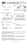
B/O CIRCUIT BOARD OPTION (FOR HEAT PUMP APPLICATIONS): This
setting is a plastic shorting cap which determines the operation of the
shared B/O wire terminal connection. This jumper must remain installed
for a Heat Pump system to be able to provide heating and cooling as
needed, and the majority of heat pumps today use the default “O”
setting. The symptoms that will occur if this setting is not correct will
be: heating while in cool mode, and cooling while in heat mode.
MANUAL DE INSTALACIÓN DEL PRODUCTO
“B” OPTION
JP2
Termostato TX100E
JP2
When this is set to “O” (factory default), the shared B/O terminal will be
turned on while in COOL mode, and off in HEAT mode.
Lux Products Corporation - Mt. Laurel, New Jersey 08054 - http://www.luxproducts.com
When this is set to “B” (which is needed for some Rheem, Ruud, and
Bard heat pumps), the shared B/O terminal will be turned on in HEAT
mode, and off in COOL mode.
WARNING: Use Energizer ® or DURACELL ® Alkaline Batteries Only.
Energizer ® is a registered trademark of Eveready Battery Company, Inc.
DURACELL ® is a registered trademark of The Procter & Gamble Company
IMPORTANT!
“O” OPTION
(default)
SYSTEM COMPATIBILITY:
HEAT / OFF / COOL, SYSTEM MODE SWITCH: Set this switch to HEAT to control your heating system,
and COOL to control your cooling system. The OFF position will disable both the heating and cooling
units.
AUTO / ON, FAN MODE SWITCH: When in AUTO, the blower fan (if present in your system) will cycle on
and off only while heating or cooling. In the ON position, the blower fan will run constantly at all times
with or without a demand for heating or cooling.
This thermostat can be used with most 24 volt: gas, oil, Millivolt, electric heating and cooling systems,
including single-stage heat pumps (WITHOUT auxiliary or emergency heat element).
SET BUTTON: This button is used to access the temperature program settings when in heat or cool
mode, and for adjusting the day and clock while in off mode.
It cannot be used with: 120/240 volt heating elements (without a transformer), or on heat pump
systems that have more than one heating or cooling stage. Ask your dealer for other LUX thermostats
to control those systems.
NEXT BUTTON: This is used when setting items such as software options, and temperature programs.
When items on the screen are flashing during adjustments, pressing the NEXT button will cycle through
which item is flashing.
CAUTIONS AND WARNINGS:
• The thermostat requires batteries to operate and failure or sub-standard performance of the batteries
may impair or prevent the correct operation of the thermostat. Use Duracell ® or Energizer ® alkaline
batteries ONLY for all LUX thermostats requiring batteries. BE SURE TO CHANGE THE BATTERIES AT
LEAST ONCE A YEAR, or whenever you see the LO BATT indication on the screen. Failure to follow
these battery instructions could result in property damage and/or personal injury.
• The electrical rating for this thermostat is 1.5 Amps per terminal, with a maximum total load of 2.0A
for all terminals combined.
• The thermostat contains parts that may wear out through use and are susceptible to failure if overloaded or used in a manner other than as indicated in the documentation.
• Check unoccupied residences regularly to ensure that all systems are operating properly.
• Check any heating/air-conditioning system including this product before operation and at regular
intervals.
HOLD BUTTON: This button activates and deactivates the manual Temperature Hold feature, which
maintains a fixed set temperature indefinitely without following a program routine. This button is not
used when ITEM #02 below is set to “3” for manual non-programmable.
UP / DOWN BUTTONS: The UP and DOWN buttons are used to control the set temperature, or adjust any
other on-screen items. Typically, an item that is flashing can currently be adjusted.
SYSTEM CONFIGURATION AND SETUP OPTIONS:
INSTALL BATTERIES INTO THERMOSTAT: Install two brand new Energizer ® or DURACELL ® “AA” size
alkaline (only) batteries, into the thermostat’s battery compartment. Ensure the batteries are installed
in the proper direction.
Setup options for how the thermostat will function, along with choosing your particular system type, are
performed using a menu on the display screen.
• Electrical interference, static electricity, failure or substandard performance of batteries, wiring
defects in the installation and/or characteristics of the connected HVAC devices may prevent the
system from regulating heating and cooling as anticipated.
TO ACCESS THE SETUP MENU: Move the System Mode switch into the OFF position, and then hold
down the SET button for approximately 5 seconds until the screen changes. The menu will always start
with item #01, and is advanced to each following item by a single press of the NEXT button. The
options for each item are changed using the UP or DOWN buttons.
• The thermostat is a sensitive device and dropping the product can cause damage to critical
components. If the product is dropped or shaken violently during transport or installation then it
should be replaced immediately.
ITEM #01 (TEMPERATURE SCALE):
[1] (default) Shows all temperature values in Fahrenheit.
[2] Shows all temperature values in Celsius.
• Persons with physical or mental limitations may not be able to promptly respond to a malfunction of
the heating/air-conditioning system.
ITEM #02 (PROGRAMMING STYLE):
[1] (default) 5/2-Day Programming. This style uses a weekday program routine for Monday, Tuesday,
Wednesday, Thursday, Friday, and a separate weekend program routine for Saturday and Sunday.
[2] 7-Day Programming. This style uses a separate program routine for each of the 7 days in the week.
[3] Manual Non-Programmable. In this setting, there are no program routines for the thermostat to
follow and the temperature control will be set only by the UP and DOWN buttons on the front panel.
• All residents should be made aware of the potential in any system for malfunctions that could cause
continuous heating or cooling and should be familiar with the operation and location of the
heating/cooling appliance on/off switch.
• Read the instruction manual completely before installing the thermostat. A more detailed product
manual is available on our www.luxproducts.com website. You should consult a qualified HVAC
technician or an electrician if you do not fully understand the installation instructions.
REMOVAL OF OLD THERMOSTAT:
1. Turn OFF the electricity to all heating and cooling components. Do not turn the electricity back on
until all work is completed.
2. Write down the letters printed near each wire terminal that is used, and also the color of each wire
that is connected to it. Self-adhesive wire labels are also enclosed.
3. Carefully remove the wires one at a time, and bend them in a manner so that they do not fall back
inside the wall. Do not allow bare wire ends to touch each other.
INSTALLATION OF NEW THERMOSTAT:
Use the wiring diagrams shown on the back of this installation sheet to find the closest match to your
particular heating and/or cooling system. Please read ALL of the Wiring Diagram Notes that are shown
above the connection diagrams, to avoid causing damage to your system or the new thermostat.
1. Strip wire insulation leaving only 3/8 in. (9.5mm) bare wire ends, and clean off any corrosion
present.
2. Fill the wall opening with non-combustible insulation to prevent drafts from affecting the
thermostat’s normal operation.
3. Route the wires through the opening in the new thermostat base plate, and install the mounting
screws.
4. If the previous holes cannot be used, hold the thermostat base against the wall so that it appears
straight and level (position the base for best appearance) and mark for the new screw holes. Attach
the base to the wall using the screws provided (use the supplied plastic anchors if needed when
mounting to a soft material such as drywall).
5. When attaching the wires to the thermostat, please ensure that the bare wire ends are held ALL the
way into the terminal block while the screw is being tightened, and be careful not to over tighten
them, as they only need to be snug.
COMPLETE THE INSTALL:
GAS / ELEC CIRCUIT BOARD OPTION (“G” TERMINAL FAN OPERATION): This setting is a plastic
shorting cap called a jumper. This jumper must remain installed, and set to either GAS or ELECTRIC for
your system to work properly. This setting changes how your system’s blower fan (if applicable) is
controlled while the thermostat is in HEAT mode, and the Fan switch is in the AUTO position. This
setting does not affect the fan operation while the thermostat is in COOL mode.
When set to “GAS”, the blower fan is controlled solely by the heating
system itself. Systems that would typically use the “GAS” setting would
be: natural gas, propane, or oil furnaces, and boilers.
NOTE: If your blower fan does not operate properly after installation, try
moving the Gas / Electric option to the “Electric” setting.
When set to “ELEC”, the blower fan is controlled directly by the
thermostat. This setting is required for heating systems that do not
control their own fan, such as HEAT PUMPS, and units that only have an
electric-resistive heating element as the heat source.
(Programable para 7 días o 5/2 días
o no programable)
ELEC
ITEM #03 (PERIOD QUANTITY):
[1] (default) 4-Periods. Thermostat uses four periods per day (called MORN, DAY, EVE, and NITE).
[2] 2-Periods. The thermostat uses only two periods per day (called DAY and NITE).
ITEM #04 (MAXIMUM HEAT SET TEMP LIMIT):
[1] (default) Limit 90F (32C). The maximum heating set temperature is 90F (32C) degrees with no heat
mode temperature restrictions.
[2] Limit 80F (27C). The maximum heating set temperature is 80F (27C) degrees.
[3] Limit 70F (21C). The maximum heating set temperature is 70F (21C) degrees.
[4] Limit 60F (16C). The maximum heating set temperature is 60F (16C) degrees.
ITEM #05 (MINIMUM COOL SET TEMP LIMIT):
[1] (default) Limit 45F (7C). The minimum cooling set temperature is 45F (7C) degrees with no cool
mode temperature restrictions.
[2] Limit 55F (13C). The maximum cooling set temperature is 55F (13C) degrees.
[3] Limit 65F (18C). The maximum cooling set temperature is 65F (18C) degrees.
[4] Limit 75F (24C). The maximum cooling set temperature is 75F (24C) degrees.
ITEM #06 (SYSTEM / EQUIPMENT TYPE):
[1] (default) Fn=Furnace. This is for the majority of heating systems such as a natural gas furnace or
hot water boiler, that are not Heat Pump systems.
[2] HP=Heat Pump. Use this setting if you have a Heat Pump system (which uses the outdoor unit as
the primary heat source). The presence of either an “O” or “B” wire on your previous thermostat would
typically indicate you have a heat pump system. This thermostat is NOT compatible with heat pumps
which also have an electric heating element as a backup heat source (called Auxiliary / Emergency
Heat). IMPORTANT: When set to “2” for HP, the circuit board Gas/Electric option must also be set to
“ELEC”, as described earlier in the “COMPLETE THE INSTALL” section.
ITEM #07 (DELAY TIME):
[1] (default) 5 Minutes. Thermostat waits 5 minutes before turning the system back on after it was last
run. The 5 minute setting is fine for most applications, and provides equipment protection by
preventing rapid cycling.
[2] Same operation as above, but reduced to 2 minutes between state changes if desired.
ADVERTENCIA: Utilice solo baterías alcalinas Energizer ® o DURACELL ®
¡IMPORTANTE!
COMPATIBILIDAD DEL SISTEMA:
Este termostato se puede utilizar con la mayoría de los sistemas de calefacción y refrigeración eléctricos de 24
voltios, a gas, petróleo o milivoltios, incluidas las bombas de calor de una sola etapa (SIN resistencia auxiliar o
de emergencia).
No se puede utilizar con: resistencias de 120/240 voltios (sin un transformador) o en sistemas de bomba de
calor que tienen más de una etapa de refrigeración o calefacción. Consulte a su distribuidor sobre otros
termostatos LUX para controlar esos sistemas.
PRECAUCIONES Y ADVERTENCIAS:
• El termostato requiere baterías para funcionar y la falla o el rendimiento deficiente de las baterías puede
afectar o impedir el correcto funcionamiento del termostato. Use SOLO baterías alcalinas Energizer® o
Duracell® para todos los termostatos LUX que requieran baterías. ASEGÚRESE DE CAMBIAR LAS BATERÍAS AL
MENOS UNA VEZ AL AÑO o cada vez que vea la indicación LO BATT (batería baja) en la pantalla. No seguir
correctamente las instrucciones de las baterías puede resultar en daños personales y/o materiales.
• La especificación eléctrica para este termostato es de 1,5 A por terminal, con una carga máxima total de 2,0
A para todas las terminales combinadas.
• El termostato contiene partes que pueden deteriorarse por medio de su uso y que son propensas a fallar si
se las sobrecarga o si se las usa de manera diferente a la indicada en la documentación.
• Revise regularmente las residencias desocupadas para asegurarse de que todos los sistemas estén
funcionando correctamente.
• Revise cualquier sistema de climatización incluido este producto antes de ponerlo en funcionamiento y en
intervalos periódicos.
• La interferencia eléctrica, la electricidad estática, la falla o rendimiento deficiente de las baterías, defectos
de cableado en la instalación y/o características de los dispositivos de calefacción, ventilación y aire
acondicionado que estén conectados pueden impedir que el sistema regule la calefacción y la refrigeración
como estaba previsto.
• El termostato es un dispositivo sensible y dejar caer el producto puede dañar componentes cruciales. Si deja
caer el producto o si lo agita violentamente durante el transporte o instalación, debería reemplazarse
inmediatamente.
• Personas con limitaciones físicas o mentales pueden no ser capaces de responder rápidamente al mal
funcionamiento del sistema de climatización.
• Todos los residentes deben ser conscientes de la posibilidad del mal funcionamiento en cualquier sistema
que podría generar la calefacción o refrigeración continua y deben estar familiarizados con la operación y
ubicación del interruptor on/off (encendido/apagado) del aparato de climatización.
• Lea el manual de instrucciones por completo antes de instalar el termostato. Un manual de producto más
detallado se encuentra disponible en nuestro sitio web www.luxproducts.com. Si no comprende las
instrucciones de instalación en su totalidad, consulte a un técnico de climatización calificado o a un
electricista.
RETIRO DEL TERMOSTATO VIEJO:
1. Desconecte la electricidad de todos los componentes de calefacción y refrigeración. No la conecte hasta que
el trabajo haya finalizado.
2. Anote las letras impresas cerca de cada terminal del cable que se utilice y también el color de cada uno de
los cables que estén conectados al terminal. También se incluyen etiquetas autoadhesivas para cables.
3. Retire cuidadosamente los cables uno a uno y dóblelos de manera que no caigan nuevamente dentro de la
pared. No permita que los extremos desnudos de los cables se toquen entre sí.
INSTALACIÓN DEL TERMOSTATO NUEVO:
Utilice los diagramas de cableado que se muestran en la parte posterior de esta hoja de instalación para
encontrar la correspondencia más cercana a su sistema de calefacción y/o refrigeración en particular. Lea
TODAS las notas del diagrama de cableado que se muestran por encima de los esquemas de conexión, para
evitar causar daños a su sistema o al nuevo termostato.
1. Pele el aislamiento del cable dejando solo extremos de cable pelado de 3/8 de pulgada (9,5 mm) en los
extremos y limpie la corrosión visible.
2. Rellene la abertura de la pared con un aislante no inflamable para evitar que las corrientes afecten el
funcionamiento normal del termostato.
3. Pase los cables a través de la abertura de la placa base del termostato nuevo e instale los tornillos de
montaje.
4. Si no pueden utilizarse los agujeros previos, mantenga la base del termostato contra la pared derecha y
nivelada (coloque la base de la manera que luzca mejor) y marque el lugar donde deberán hacerse los
nuevos agujeros para los tornillos. Sujete la base a la pared con los tornillos incluidos (utilice los anclajes de
plástico provistos de ser necesario, cuando instale el termostato en un material blando como por ejemplo
paneles de yeso).
5. Al conectar los cables al termostato, asegúrese de que los extremos desnudos de los cables se mantengan
COMPLETAMENTE en el bloque de terminales mientras que el tornillo se aprieta y tenga cuidado de no
apretarlos demasiado ya que solo tienen que estar bien ajustados.
COMPLETE LA INSTALACIÓN:
OPCIÓN DE TARJETA DE CIRCUITOS GAS/ELEC. (FUNCIONAMIENTO DEL VENTILADOR DEL TERMINAL “G”):
Esta opción es una tapa de cortocircuito de plástico llamada puente. Este puente debe permanecer instalado y
configurado a GAS o ELECTRIC (electricidad) para que el sistema funcione correctamente. Esta configuración
cambia la forma en la cual se controla el ventilador de su sistema (si es aplicable), mientras que el termostato
esté en modo HEAT (calefacción) y el interruptor del ventilador esté en la posición AUTO (automático). Este
ajuste no afecta el funcionamiento del ventilador, mientras que el termostato está en el modo COOL
(refrigeración).
ITEM #09 (TEMPERATURE CALIBRATION):
[0 (zero)] (default) At zero, there are no changes made to the base room temperature measurement.
The adjustment is from as low as subtracting –5F (–3C) degrees from the room temperature, to as high
as adding +5F (+3C) degrees to the room temperature. The internal temperature sensor is accurately
calibrated at the factory, and in most cases this setting should not need to be altered.
Cuando se establece en “GAS”, únicamente el sistema de calefacción controla el ventilador. Los sistemas que
usarían habitualmente la configuración “GAS” serían: estufas y calderas a gas natural, propano o petróleo.
JP1
JP1
• Ponga una etiqueta para designar cada una de los terminales del cableado del termostato
actual antes de retirar el termostato que se ha de reemplazar.
• No haga caso a los colores de los cables, ya que es posible que no cumplan con ninguna
norma. Conecte los cables usando las designaciones por letras para los terminales.
Move the System Mode switch into the OFF position, and press the SET button once. The Day on the
top of the display should begin flashing, which can be adjusted using UP or DOWN. Press the NEXT
button and the clock time should start flashing, which can be adjusted using UP or DOWN. Make sure
the AM/PM indication shown is correct, and holding the UP or DOWN buttons will make the clock digits
scroll rapidly. When complete, press the NEXT button to return to the normal operating screen.
© 2014 LUX PRODUCTS CORPORATION. ALL RIGHTS RESERVED
NOTA: Si su ventilador no funciona adecuadamente después de la
instalación, cambie la opción de gas o electricidad a la posición de ajuste
de “Electric”.
Cuando se establece en “ELEC”, el ventilador está controlado directamente
por el termostato. Esta configuración es necesaria para los sistemas de
calefacción que no controlan su propio ventilador, tales como BOMBAS DE
CALOR, y las unidades que solo tienen un elemento de calentamiento
eléctrico resistivo como fuente de calor.
OPCIÓN “B”
JP2
JP2
OPCIÓN “O”
(por defecto)
Cuando se establece en “B” (necesario para algunas bombas de calor Rheem, Ruud
y Bard), el terminal compartido B/O se enciende en el modo HEAT (calefacción) y se
apaga en el modo COOL (refrigeración).
Energizer ® es una marca registrada de Eveready Battery Company, Inc.
DURACELL ® es una marca registrada de The Procter & Gamble Company
ITEM #08 (TEMPERATURE SWING):
[1] (default) This is the tightest control, which is plus/minus 0.25F (0.14C) degrees from the target set
temperature.
[2 through 9] These alternate values make the temperature control wider with more variation. Each
incremental setting number adds an additional 0.25F (0.14F) degrees onto the initial setting. [9] is the
widest control setting, which is plus/minus 2.25F (1.25C) degrees from the set temperature.
SET DAY AND TIME:
GAS
(default)
Cuando se ajusta en “O” (predeterminado de fábrica), el terminal compartido B/O
se encenderá mientras que se encuentra en el modo COOL (refrigeración) y se
apagará en el modo HEAT (calefacción).
Lux Products Corporation - Mt. Laurel, New Jersey 08054 - http://www.luxproducts.com
FRONT PANEL CONTROLS:
• Label every wire terminal designation on your existing thermostat wiring before removing
your old thermostat.
• Ignore the color of the wires since they may not comply with any standard. Please
connect wires using the terminal letter designations.
53574
OPCIÓN DE TARJETA DE CIRCUITOS B/O
(PARA APLICACIONES DE BOMBA DE CALOR):
Esta configuración es una tapa de plástico de cortocircuito que determina el
funcionamiento de la conexión terminal del cable de B/O compartida. Este puente
debe permanecer instalado para que un sistema de bomba de calor pueda
proporcionar calefacción y refrigeración según sea necesario, y la mayoría de las
bombas de calor hoy en día utilizan la configuración predeterminada “O”. Los
síntomas que se producen si este ajuste no es correcto serán: calefacción
vmientras se encuentra en el modo de refrigeración y refrigeración mientras se
encuentra en modo de calefacción.
CONTROLES DEL PANEL FRONTAL:
INTERRUPTOR DE MODO DEL SISTEMA HEAT/OFF/COOL (CALEFACCIÓN/APAGADO/REFRIGERACIÓN): Ponga
el interruptor en HEAT (calefacción) para controlar su sistema de calefacción y en COOL (refrigeración) para
controlar su sistema de refrigeración. La posición de OFF (apagado) desactivará las unidades de calefacción y
de refrigeración.
INTERRUPTOR DE MODOS DEL VENTILADOR AUTO/ON (AUTOMÁTICO/ENCENDIDO): Cuando este interruptor
está en AUTO (automático), el ventilador (de existir en su sistema) se encenderá y apagará automáticamente
mientras funcionen la calefacción o la refrigeración. Cuando el interruptor esté en la posición de ON
(encendido), el ventilador funcionará constantemente en todo momento con o sin demanda de calefacción o el
refrigeración.
BOTÓN SET (CONFIGURACIÓN): Este botón se utiliza para acceder a la configuración del programa de
temperatura cuando se encuentra en modo de calefacción o refrigeración, y para ajustar el día y el reloj en el
modo de apagado.
BOTÓN NEXT (SIGUIENTE): Este botón se usa mientras se configuran elementos tales como opciones del
software y programas de temperatura. Cuando los elementos de la pantalla parpadean durante los ajustes,
pulsar el botón de NEXT (siguiente) permitirá cambiar el elemento que está parpadeando.
BOTÓN HOLD (MANTENIMIENTO): Este botón activa y desactiva la función Mantenimiento de temperatura
manual que mantiene una temperatura de consigna fija de manera indefinida sin seguir la rutina de un
programa. Este botón no se utiliza cuando el ELEMENTO N.° 02 a continuación se establece en “3” para la
configuración manual no programable.
BOTONES UP/DOWN (ARRIBA/ABAJO): Los botones UP (arriba) y DOWN (abajo) se utilizan para controlar la
temperatura del sistema o ajustar otros elementos que aparecen en pantalla. Por lo general, un elemento que
está parpadeando se puede ajustar ahora.
CONFIGURACIÓN DEL SISTEMA Y OPCIONES DE CONFIGURACIÓN:
INSTALAR LAS BATERÍAS EN EL TERMOSTATO: Instale dos baterías alcalinas (solamente) nuevas Energizer® o
DURACELL®, tamaño “AA” en el compartimiento para las baterías del termostato. Asegúrese de que las baterías
estén instaladas en la dirección correcta.
Las opciones de configuración para cómo funcionará el termostato, junto con la elección de su tipo de sistema
particular, se realizan mediante un menú en la pantalla de visualización.
PARA ACCEDER AL MENÚ SETUP (CONFIGURACIÓN): Mueva el interruptor System Mode (modos del sistema)
a la posición OFF (apagado) y luego mantenga pulsado el botón SET (configurar) durante aproximadamente 5
segundos hasta que la pantalla cambie. El menú siempre comenzará con el elemento N.° 01 y avanza a cada
punto siguiente al presionar sola vez el botón NEXT (siguiente). Las opciones de cada elemento cambian con
los botones UP (arriba) o DOWN (abajo).
ELEMENTO N.° 01 (ESCALA DE TEMPERATURA):
[1] (por defecto) Muestra todos los valores de temperatura en grados Fahrenheit.
[2] Muestra todos los valores de temperatura en grados Celsius.
ELEMENTO N.° 02 (ESTILO DE PROGRAMACIÓN):
[1] (por defecto) Programación de 5/2 días. Este estilo utiliza una rutina de programa de días de semana para
el lunes, martes, miércoles, jueves, viernes, y una rutina de programa de fin de semana por separado para el
sábado y el domingo.
[2] Programación de 7 días. Este estilo utiliza una rutina de programa separado para cada uno de los 7 días de
la semana.
[3] Manual no programable. En esta configuración, no hay rutinas de programa para que el termostato siga y el
control de temperatura se configurará únicamente mediante los botones UP (arriba) y DOWN (abajo) del panel
delantero.
ELEMENTO N.° 03 (CANTIDAD DE PERÍODOS):
[1] (por defecto) 4 períodos. El termostato utiliza cuatro periodos por día (llamados MORN [MAÑANA], DAY
[DÍA], EVE [TARDE] y NITE [NOCHE]).
[2] 2 períodos. El termostato utiliza solamente dos periodos por día (llamados DAY [DÍA] y NITE [NOCHE]).
ELEMENTO N.° 04 (LÍMITE DE TEMPERATURA DE AJUSTE DE CALEFACCIÓN MÁXIMA):
[1] (por defecto) Límite de 90°F (32°C). La temperatura de ajuste de calefacción máxima es de 90°F (32°C) sin
restricciones de temperatura en modo de calefacción.
[2] Límite de 80°F (27°C). La temperatura de ajuste de calefacción máxima es de 80°F (27°C).
[3] Límite de 70°F (21°C). La temperatura de ajuste de calefacción máxima es de 70°F (21°C).
[4] Límite de 60°F (16°C). La temperatura de ajuste de calefacción máxima es de 60°F (16°C).
ELEMENTO N.° 05 (LÍMITE DE TEMPERATURA DE AJUSTE DE REFRIGERACIÓN MÍNIMA):
[1] (por defecto) Límite de 45°F (7°C). La temperatura de ajuste de refrigeración mínima es de 45°F (7°C) sin
restricciones de temperatura en modo de refrigeración.
[2] Límite de 55°F (13°C). La temperatura de ajuste de refrigeración mínima es de 55°F (13°C).
[3] Límite de 65°F (18°C). La temperatura de ajuste de refrigeración mínima es de 65°F (18°C).
[4] Límite de 75°F (24°C). La temperatura de ajuste de refrigeración máxima es de 75°F (24°C).
ELEMENTO N.° 06 (TIPO DE SISTEMA/EQUIPO):
[1] (por defecto) Fn = estufa. Esto es para la mayoría de los sistemas de calefacción, como una estufa o
caldera de agua caliente a gas natural, que no son sistemas de bombas de calor.
[2] HP = bomba de calor. Use este ajuste si tiene un sistema de bomba de calor (que utiliza la unidad exterior
como la fuente primaria de calor). La presencia de un cable “O” o “B” en su termostato anterior por lo general
indica que tiene un sistema de bomba de calor. Este termostato NO es compatible con bombas de calor, que
también tienen una resistencia eléctrica como fuente de calor de respaldo (llamada calefacción auxiliar/de
emergencia). IMPORTANTE: Cuando se establece en “2” para HP, la opción Gas/Electric (gas/electricidad) de la
placa de circuito también se debe establecer en “ELEC”, como se describe anteriormente en la sección
“Realización de la instalación”.
ELEMENTO N.° 07 (TIEMPO DE RETARDO):
[1] (por defecto) 5 minutos. El termostato espera 5 minutos antes de encender el sistema de nuevo después de
que lo operó por última vez. El ajuste de 5 minutos es correcto para la mayoría de aplicaciones y ofrece la
protección del equipo mediante la prevención de ciclos rápidos.
[2] Es la misma operación que el anterior, pero reducida a 2 minutos entre cambios de estado si lo desea.
ELEMENTO N.° 08 (CAMBIO DE TEMPERATURA):
[1] (por defecto) Este es el control más ajustado, que es más/menos 0,25°F (0,14°C) con respecto a la
temperatura de ajuste objetivo.
[2 a 9] Estos valores alternativos hacen que el control de temperatura sea más amplio, con más variación.
Cada número de ajuste de aumento gradual añade 0,25°F (0,14°F) adicionales a la configuración inicial. [9] es
el ajuste de control más amplio, que es más/menos 2,25°F (1,25°C) grados de la temperatura de ajuste.
ELEMENTO N.° 09 (CALIBRACIÓN DE TEMPERATURA):
[0 (cero)] (por defecto) En cero, no hay cambios en la medición de la temperatura ambiente de base. El ajuste
es desde un nivel que se determina restando –5°F (–3°C) a la temperatura ambiente, a un nivel que se
determina sumando +5°F (+3°C) a la temperatura ambiente. El sensor de temperatura interna se calibra con
precisión en la fábrica y, en la mayoría de los casos, no debería ser necesario modificar este ajuste.
CONFIGURAR DÍA Y HORA:
ELEC
(ELECTRICIDAD)
JP1
GAS
(por defecto)
Mueva el interruptor System Mode (modos del sistema) a la posición OFF (apagado) y pulse el botón SET
(configurar) una vez. El día en la parte superior de la pantalla debería comenzar a parpadear, con lo cual se
puede ajustar utilizando las teclas UP (arriba) o DOWN (abajo). Pulse el botón NEXT (siguiente) y la hora del
reloj debería empezar a parpadear, con lo cual se puede ajustar utilizando las teclas UP (arriba) o DOWN
(abajo). Asegúrese de que la indicación AM/PM que se muestra sea correcta y mantener presionados los
botones UP (arriba) o DOWN (abajo) hará que los dígitos del reloj se desplacen rápidamente. Cuando termine,
pulse el botón NEXT (siguiente) para volver a la pantalla de funcionamiento normal.
JP1
© 2014 LUX PRODUCTS CORPORATION. TODOS LOS DERECHOS RESERVADOS
DESCARGUE EL MANUAL DE INSTRUCCIÓN COMPLETO DE NUESTRO SITIO WEB:
CALEFACCIÓN BÁSICA Y OPERACIÓN DE ENFRIAMIENTO:
Esta hoja contiene las instrucciones básicas de instalación y configuración. Hay otros temas que se tratan con
mayor detalle, en la versión completa del manual para este termostato. El manual completo en PDF se puede
descargar en http://www.luxproducts.com. Haga clic en SUPPORT (asistencia) y luego en INSTRUCTION
MANUALS (manuales de instrucciones). Muchos modelos de termostatos tienen letras de “revisión” en
minúscula después del nombre del modelo (por ejemplo, TX1500Ua). Por favor, elija el manual que coincida
exactamente con el número de modelo que aparece en su termostato en particular.
DOWNLOAD FULL INSTRUCTION MANUAL FROM OUR WEBSITE:
El funcionamiento básico de su sistema de calefacción o refrigeración se puede activar mediante la selección
de HEAT (calefacción) o COOL (refrigeración) que están en el interruptor System Mode (Modos del sistema) y
empleando UP (arriba) o DOWN (abajo) para ajustar la temperatura. Para mantener una única temperatura fija,
puede utilizar el botón HOLD (mantener). Si hay un candado en la pantalla de visualización, la función de
bloqueo del teclado numérico está activada (ambos interruptores deslizantes de modo todavía funcionan).
KEYPAD LOCKOUT:
1) Si los diagramas de cableado no representan o no coincide claramente con su sistema, por favor consulte la
sección “ASISTENCIA TÉCNICA” a continuación y comuníquese con nosotros antes de retirar cualquier cable
de su termostato actual.
2) Todos los cables marcados con LÍNEAS PUNTEADAS que se muestran en los diagramas de cableado son
opcionales o su uso depende del tipo de su sistema específico (EJEMPLO: El diagrama N.° 1 muestra el
cable del ventilador como opcional. Esto no infiere que su sistema no tiene un ventilador, solo que es
posible que no haya un cable para este).
3) Las letras de los terminales que se muestran en negro representan el uso de cableado típico. Las letras de
los terminales que se muestran en gris representan otras posibles designaciones en el cableado que podría
observar en la marca y modelo específico de su termostato.
4) El terminal “C” opcional se usa para proporcionar alimentación eléctrica al termostato por medio del sistema
de 24 voltios proporcionado por su sistema de climatización, mediante el cable común del sistema. Este se
puede usar solo o además de la instalación de baterías a modo de respaldo. NOTA: al emplear baterías, la
conexión del cable común del sistema al termostato no es necesaria para que la calefacción y la
refrigeración funcionen correctamente.
5) Si el termostato anterior tiene TANTO un cable “O” y “B” presentes, entonces es probable que “B” sea un
cable común del sistema (cable de alimentación) y puede conectarse al terminal “C” o encintarse y no
usarse. Conectar un cable común del sistema al terminal “B/O” de este termostato puede dañar el
termostato e incluso el equipo que integra su sistema de calefacción y refrigeración.
6) Si las conexiones de su termostato existentes contienen un cable etiquetado como “W2”, “AUX”, “E” o “X2”,
esto indicaría que tiene etapas de calefacción adicionales presentes. Este es un termostato de una sola
etapa y no puede adaptarse a ninguno de estos componentes del sistema. Usted tendrá que seleccionar un
modelo diferente.
7) Si está remplazando un termostato que cuenta con un reloj mecánico en el panel delantero, puede haber
DOS cables marcados como “C” para la alimentación del reloj. No conecte ninguno de los dos a este
termostato.
Los botones del panel delantero se pueden bloquear para evitar la manipulación no autorizada de la
temperatura de ajuste y otros parámetros. Ni el interruptor System Mode (modos del sistema) o Fan Mode
(modos del ventilador) se bloquean, y cuando el bloqueo del teclado numérico está activo, habrá un icono de
candado que se muestra en la pantalla.
Para bloquear o desbloquear los botones del teclado numérico, seleccione HEAT (calefacción) o COOL
(refrigeración) en el interruptor System Mode (modos del sistema) y pulse la siguiente secuencia de cuatro
botones: NEXT, NEXT, NEXT, HOLD.
PROGRAMACIÓN DE TEMPERATURA:
En forma predeterminada, este termostato tiene 4 períodos de programas distintos tanto para el modo Heat
(calefacción) como para el modo Cool (refrigeración): MORN, DAY, EVE y NITE (MAÑANA, DÍA, TARDE y NOCHE).
Cada periodo termina a la hora en que comienza el siguiente. Los programas de temperatura de calefacción se
establecen cuando el selector de modos está en la posición HEAT, y los programas de temperatura de
refrigeración se establecen cuando el selector de modo está en COOL.
NOTA: Si el termostato está configurado para usar solo 2 períodos por día (en lugar del valor predeterminado
de fábrica de 4 períodos por día), el termostato únicamente usará las designaciones de período DAY (día) y
NITE (noche). Los períodos MORN (mañana) y EVE (tarde) no se usará ni se verán en la pantalla.
PARA DEFINIR UN PROGRAMA DE TEMPERATURA: Elija el modo HEAT (calefacción) o COOL (refrigeración) y
pulse el botón SET (configurar). La programación se iniciará con la posición PROG. Use UP (arriba) o DOWN
(abajo) para ajustar la hora de inicio del primer período y luego presione el botón NEXT (siguiente) para
avanzar. Use UP (arriba) o DOWN (abajo) para ajustar la temperatura para el primer período y luego presione el
botón NEXT (siguiente) para avanzar. Ahora, ajuste la hora de inicio y la temperatura para el segundo periodo,
presione NEXT luego de cada elemento para continuar. Repita estos mismos pasos para ajustar las horas de
inicio y establecer temperaturas para el tercer y cuarto períodos (si están presentes).
Cuando el último período terminó para cada día (o grupo de días), el termostato avanzará al siguiente día (o
grupo de días).
ASISTENCIA TÉCNICA:
Cuando haya finalizado, puede pulsar el botón SET (configurar) para guardar los cambios y volver al modo de
funcionamiento normal.
Si tiene algún problema para instalar o usar este termostato, lea con cuidado y detenimiento el manual de
instrucciones. Si aún así necesita asistencia técnica, comuníquese con nuestro departamento de Asistencia
Técnica al 856-234-8803 en el horario normal de oficina, de 8:00 a.m. a 4:30 p.m. hora del este, de lunes a
viernes. También puede recibir asistencia técnica a cualquier hora del día y la noche, en
http://www.luxproducts.com. Nuestro sitio Web ofrece guías para resolver problemas, respuestas a las
preguntas técnicas más frecuentes y también le permite enviar sus preguntas por correo electrónico a nuestro
personal de asistencia técnica, según su propia conveniencia.
NOTA: Si no se desea una rutina de programa de temperatura, es posible cambiar el ELEMENTO N.° 02 en las
Setup Options (opciones de configuración) a “3” para el modo manual no programable.
Basic operation of your heating or cooling system can be obtained by selecting HEAT or COOL on the
System Mode switch, and using UP or DOWN to adjust the temperature. To maintain a single fixed
temperature, you can use the HOLD button. If there is a padlock present on the display screen, the
keypad lockout feature is enabled (both of the mode slide switches are still functional).
This sheet contains basic installation and setup instructions. There are additional topics covered in
greater detail, in the full version of the manual for this thermostat. The full PDF manual can be
downloaded at http://www.luxproducts.com. Click on SUPPORT, then INSTRUCTION MANUALS. Many
thermostat models have lower case “revision” letters after the model name (i.e. TX1500Ua). Please
choose the manual that exactly matches the model number shown on your particular thermostat.
WIRING DIAGRAM NOTES:
NOTAS DEL DIAGRAMA DEL CABLEADO:
BLOQUEO DEL TECLADO:
BASIC HEATING AND COOLING OPERATION:
53574
1) If the wiring diagrams do not clearly represent or match your system, please refer to “TECHNICAL
ASSISTANCE” below, and contact us before removing any of your existing thermostat wires.
The front panel buttons can be locked out to prevent unauthorized tampering of the set temperature and
other settings. Neither the System Mode or Fan Mode slide switches are locked out, and when the
Keypad Lockout is active, there will be a padlock icon shown in the display screen.
2) All of the DASHED wires shown in the wiring diagrams are either optional, or their usage depends
upon your specific system type (EXAMPLE: Diagram #1 shows the fan wire as optional. This does not
infer that your system does not have a fan, only that there may not be a wire for it).
To lock or unlock the keypad buttons, first select either HEAT or COOL on the System Mode switch, and
press the following four-button sequence: NEXT, NEXT, NEXT, HOLD.
3) The terminal letters shown in black represent typical wiring usage. The terminal letters shown in
gray represent other possible wiring letter designations that you might see on your particular brand
and model of thermostat.
TEMPERATURE PROGRAMMING:
4) The optional “C” terminal is used for powering the thermostat by the 24 volts supplied by your
heating/cooling system, using the System Common wire. This can be used alone, or in addition to
installing batteries as a backup. NOTE: when using batteries, connecting the System Common wire
to the thermostat is not necessary for heating and cooling to function properly.
By default, this thermostat has 4 separate program periods for both Heat and Cool modes, they are:
MORN, DAY, EVE, and NITE. Each period ends at the start time of the next upcoming period. The Heat
temperature programs are set while the mode switch is in the HEAT position, and the Cool temperature
programs are set while the mode switch is in COOL.
5) If your old thermostat has BOTH an “O” wire and a “B” wire present, then “B” is likely a System
Common (power wire) and can either be connected to the “C” terminal, or taped off and unused.
Connecting a System Common wire to this thermostat’s “B/O” terminal will damage the thermostat,
and also your heating and cooling system equipment.
NOTE: If the thermostat is configured to use only 2 periods per day (instead of the factory default of 4
periods per day), the thermostat will only use the DAY and NITE period designations. The MORN and
EVE periods will not be used or visible on the screen.
6) If your existing thermostat connections contain a wire labeled as “W2”, “AUX”, “E”, or “X2”, this
would indicate that you have additional heating stages present. This is a single-stage thermostat,
and cannot accomodate any of these system components. You will need to select a different model.
TO SET A TEMPERATURE PROGRAM: Choose either HEAT or COOL mode, and press the SET button.
Programming will start with PROG position. Use UP or DOWN to adjust the start time for the first
period, and then press the NEXT button to advance. Use UP or DOWN to adjust the set temperature for
the first period, and then press the NEXT button to advance. Now adjust the start time and set
temperature for the second period, pressing NEXT after each item to advance. Continue with these
same steps to adjust the start times and set temperatures for the third and fourth periods (if present).
7) If replacing an old thermostat that has a mechanical time clock on the front panel, there may be TWO
wires labeled as “C” for the clock power. Do not connect either of them to this thermostat.
TECHNICAL ASSISTANCE:
When the last period is finished for each day (or group of days), the thermostat will advance forward
into the next day (or group of days).
If you have any problems installing or using this thermostat, please carefully and thoroughly review the
instruction manual. If you still require assistance, please contact our Technical Assistance department
at 856-234-8803 during regular business hours between 8:00AM and 4:30PM Eastern Time, Monday
through Friday. You can also receive technical assistance online anytime day or night at
http://www.luxproducts.com. Our website offers you troubleshooting guides, answers to the most
common technical questions, and also permits you to email your questions to our technical support staff
at your convenience.
When you are complete, you can press the SET button to save your changes and return back to the
normal run mode.
NOTE: If a temperature program routine is not desired, you may change ITEM #02 in the Setup Options
to “3” for manual non-programmable.
53572
2 / 3 / 4 CABLES
2 / 3 / 4 CABLES
3 / 4 / 5 CABLES
2 / 3 / 4 WIRES
2 / 3 / 4 WIRES
3 / 4 / 5 WIRES
CONVENCIONAL, SIN BOMBA DE CALOR
1 ETAPA, CALEFACCIÓN SOLAMENTE
(INCLUIDO MILIVOLTIO)
CONVENCIONAL, SIN BOMBA DE CALOR
1 ETAPA, REFRIGERACIÓN SOLAMENTE
CONVENCIONAL, SIN BOMBA DE CALOR
CALEFACCIÓN DE 1 ETAPA Y REFRIGERACIÓN DE 1 ETAPA
CONVENTIONAL, NON HEAT PUMP
1-STAGE, HEAT ONLY
(INCLUDING MILLIVOLT)
CONVENTIONAL, NON HEAT PUMP
1-STAGE, COOL ONLY
CONVENTIONAL, NON HEAT PUMP
1-STAGE HEAT AND 1-STAGE COOL
CABLE COMÚN DEL SISTEMA
OPCIONAL
N.° 1
Cable
de puente
RH-RC
instalado
de fábrica
C
X
G
F
R
RH
VENTILADOR
V
TRANSFORMADOR DE
CALEFACCIÓN DE 24V
W W1 4
CABLE COMÚN DEL SISTEMA
OPCIONAL
N.° 2
Cable
de puente
RH-RC
instalado
de fábrica
C
X
G
F
R
VENTILADOR
RC
V
TRANSFORMADOR DE
REFRIGERACIÓN DE 24V
Y1
6
UNIDAD DE
A/C
NOTA: LAS LETRAS NEGRAS DE TERMINALES SON CONVENCIONALES,
LAS LETRAS GRISES DE TERMINALES SON ESPECÍFICAS DE CADA MARCA
NOTA: LAS LETRAS NEGRAS DE TERMINALES SON CONVENCIONALES,
LAS LETRAS GRISES DE TERMINALES SON ESPECÍFICAS DE CADA MARCA
4 / 5 / 6 CABLES
CONVENCIONAL, SIN BOMBA DE CALOR
CALEFACCIÓN DE 1 ETAPA Y REFRIGERACIÓN DE 1 ETAPA,
CON DOS TRANSFORMADORES
CABLE COMÚN DEL SISTEMA
OPCIONAL
RETIRE
Cable de
puente
RH-RC
de fábrica
C
X
G
F
RH
R
V
TRANSFORMADOR DE
CALEFACCIÓN DE 24V
RC
R
V
TRANSFORMADOR DE
REFRIGERACIÓN DE 24V
Y
Y1
6
CALENTADOR
UNIDAD DE
A/C
X
G
F
R
RH
VENTILADOR
V
Y
Y1
6
TRANSFORMADOR
DE 24V
OPTIONAL
SYSTEM COMMON
#1
Factory
RH-RC
Jumper
Wire
Installed
C
X
G
F
R
RH
FAN
V
W W1 4
CALENTADOR
24V HEAT
TRANSFORMER
Factory
RH-RC
Jumper
Wire
Installed
C
X
G
F
R
RC
V
24V COOL
TRANSFORMER
Y
Y1
6
A/C
UNIT
NOTE: THE BLACK TERMINAL LETTERS ARE TYPICAL,
GRAY TERMINAL LETTERS ARE BRAND SPECIFIC
3 / 4 / 5 CABLES
4 / 5 / 6 WIRES
3 / 4 / 5 WIRES
SISTEMAS DE BOMBAS DE CALOR
CALEFACCIÓN DE 1 ETAPA Y
REFRIGERACIÓN DE 1 ETAPA SOLAMENTE,
SIN CALEFACCIÓN AUXILIAR/DE EMERGENCIA
CONVENTIONAL, NON HEAT PUMP
1-HEAT / 1-COOL, WITH TWO-TRANSFORMERS
HEAT PUMP SYSTEMS
1-HEAT / 1-COOL ONLY,
WITH NO AUXILIARY / EMERG. HEAT
N.° 5
Cable
de puente
RH-RC
instalado
de fábrica
Para bombas
de calor
SOLAMENTE,
Añadir segundo
cable puente
(suministrado)
C
X
G
F
R
RC
B*
CABLE COMÚN DEL SISTEMA
OPCIONAL
VENTILADOR
V
TRANSFORMADOR
DE 24V
OPTIONAL
SYSTEM COMMON
#4
REMOVE
Factory
RH-RC
Jumper
Wire
C
X
G
F
RH
R
V
24V HEAT
TRANSFORMER
RC
R
V
24V COOL
TRANSFORMER
Y
Y1
O
B*
6
DE BOMBA
DE CALOR
Y
Y1
6
HEATER
A/C
UNIT
VÁLVULA
DE INVERSIÓN
NOTA: LAS LETRAS NEGRAS DE TERMINALES SON CONVENCIONALES,
LAS LETRAS GRISES DE TERMINALES SON ESPECÍFICAS DE CADA MARCA
#5
FAN
W W1 4
Factory
RH-RC
Jumper
Wire
Installed
For Heat-Pumps
ONLY, Add
Second
Jumper Wire
(Supplied)
B*
OPTIONAL
SYSTEM COMMON
C
X
G
F
R
RC
V
24V
TRANSFORMER
Y
Y1
6
HEAT
PUMP
O
B*
FAN
REVERSING
VALVE
* Heat-Pump: if “O” and “B” are both present,
install old “B” wire onto “C” terminal.
NOTE: THE BLACK TERMINAL LETTERS ARE TYPICAL,
GRAY TERMINAL LETTERS ARE BRAND SPECIFIC
Factory
RH-RC
Jumper
Wire
Installed
C
X
G
F
R
RH
FAN
V
W W1 4
UNIDAD DE
A/C
NOTA: LAS LETRAS NEGRAS DE TERMINALES SON CONVENCIONALES,
LAS LETRAS GRISES DE TERMINALES SON ESPECÍFICAS DE CADA MARCA
OPTIONAL
SYSTEM COMMON
#3
FAN
HEATER
* Bomba de calor: si “O” y “B” están presentes,
instale el cable anterior “B” en el terminal “C”.
NOTA: LAS LETRAS NEGRAS DE TERMINALES SON CONVENCIONALES,
LAS LETRAS GRISES DE TERMINALES SON ESPECÍFICAS DE CADA MARCA
OPTIONAL
SYSTEM COMMON
#2
NOTE: THE BLACK TERMINAL LETTERS ARE TYPICAL,
GRAY TERMINAL LETTERS ARE BRAND SPECIFIC
VENTILADOR
W W1 4
Cable
de puente
RH-RC
instalado
de fábrica
C
W W1 4
CALENTADOR
Y
N.° 4
CABLE COMÚN DEL SISTEMA
OPCIONAL
N.° 3
NOTE: THE BLACK TERMINAL LETTERS ARE TYPICAL,
GRAY TERMINAL LETTERS ARE BRAND SPECIFIC
Y
Y1
6
24V
TRANSFORMER
HEATER
A/C
UNIT
NOTE: THE BLACK TERMINAL LETTERS ARE TYPICAL,
GRAY TERMINAL LETTERS ARE BRAND SPECIFIC