1
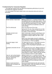
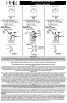
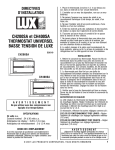
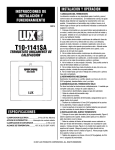
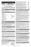
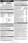
LUX ® TX9100U UNIVERSAL PROGRAMMABLE THERMOSTAT
QUICK START INSTALLATION GUIDE
1
W
53000
2
OFF
Y
G
SHUT OFF POWER
LABEL WIRES
Turn OFF the power to both
your heating and cooling units
at the circuit breaker.
3
R
BEFORE removing thermostat, label your
existing wire connections with the labels
provided. Cover any “unused” wires with
electrical tape.
4
5
6
A
AU
C
C1
DH
E
F
H
H1
H2 MDO
O
OT
OT
R
R
L
RH
T
TC
V
V
INSTALL NEW THERMOSTAT BASE
4
W3 E G Y R O W2 B L
INSTALL ALKALINE BATTERIES
G
O
R
Restore the power to your heating and cooling units.
Remove your old thermostat. Install the new thermostat
base (using the same mounting holes if possible). Connect
the wires matching the exact terminal letters from your wires,
to the terminal letters on the new thermostat.
Install new Alkaline batteries into the thermostat. NOTE:
Please use Duracell or Energizer Alkaline batteries ONLY for
all LUX ® thermostats requiring batteries. BE SURE TO
CHANGE THE BATTERIES AT LEAST ONCE A YEAR, to ensure
consistent and reliable operation of your heating/cooling
system.
NOTE: If you have both a “B” and an “O” wire, see the notes
on the back page of this instruction sheet.
5
TEST HEAT AND COOL OPERATION
HEAT
OFF
COOL
6
Set the system switch to the
desired temperature mode.
Adjust the SET Temperature to the
desired comfort setting.
(NOTE: this set point will only be
temporary until the program
periods are saved in memory.)
72F
70F
68F
SET THE CLOCK...
SET THE TEMPERATURE PROGRAMS
Thank you for choosing LUX Products, and
we hope that you will enjoy using your new
thermostat along with its many energy
saving features.
DOWNLOAD THE FULL INSTRUCTION MANUAL
This sheet is just a quick start guide, and there are many more instructions and topics covered in the full version of the manual for
this product. The complete version PDF can be obtained at “http://www.luxproducts.com”. Click on SUPPORT, then
INSTRUCTION MANUALS.
ONLINE THERMOSTAT TROUBLESHOOTING GUIDES
If you are having difficulties with the installation or the operation of your thermostat, please review the online troubleshooting
guides for your model. These troubleshooting guides cover the most common symptoms that you may observe. The
Troubleshooting Guides are located at “http://www.luxproducts.com”. Click on SUPPORT, then TROUBLESHOOTING GUIDES.
CONTACT OUR TECHNICAL SUPPORT DEPARTMENT
If you require need assistance with your product, please contact our Technical Assistance department between 8:00AM and
4:30PM Eastern Time from Monday through Friday, at 856-234-8803. Our website also permits you to email your technical
questions to our support staff at your convenience by visiting “http://www.luxproducts.com”, and clicking on the CONTACT US tab
at the top of the page.
© 2012 LUX PRODUCTS CORPORATION. ALL RIGHTS RESERVED
TX9100U QUICK START WIRING GUIDE
53000
WIRING DIAGRAM NOTES:
CAUTIONS AND WARNINGS:
•
Label every wire terminal designation on your existing thermostat
wiring before removing your old thermostat.
•
•
Ignore the color of the wires since they may not comply with any
standard. Please connect wires using the terminal letter designations.
•
WARNING: All wiring must conform to the local codes and ordinances
that are in your particular location.
The thermostat requires batteries to operate and failure or substandard performance of the batteries may impair or prevent the
correct operation of the thermostat. Use Duracell or Energizer alkaline
batteries ONLY for all Lux thermostats requiring batteries. BE SURE TO
CHANGE THE BATTERIES AT LEAST ONCE A YEAR. Failure to follow
these battery instructions could result in property damage and/or
personal injury.
•
If the information provided in the following wiring diagrams does not
clearly represent or match your system, please refer to the full version
of the manual which can be obtained from our website, or contact us
before removing your existing thermostat wires.
•
The electrical rating for this thermostat is 1.5 Amps per terminal, with a
maximum total load of 3.0A for all terminals combined.
•
The thermostat contains parts which may wear out through use and are
susceptible to failure if over-loaded or used in a manner other than as
indicated in the documentation.
•
Check unoccupied residences regularly to ensure that all systems are
operating properly.
•
Check any heating/air-conditioning system including this product
before operation and at regular intervals.
•
Electrical interference, static electricity, failure or substandard
performance of batteries, wiring defects in the installation and/or
characteristics of the connected HVAC devices may prevent the system
from regulating heating and cooling as anticipated.
•
The thermostat is a sensitive device and dropping the product can
cause damage to critical components. If the product is dropped or
shaken violently during transport or installation then it should be
replaced immediately.
•
Persons with physical or mental limitations may not be able to
promptly respond to a malfunction of the heating/air-conditioning
system.
•
All residents should be made aware of the potential in any system for
malfunctions that could cause continuous heating or cooling and
should be familiar with the operation and location of the
heating/cooling appliance on/off switch.
•
Read the instruction manual completely before installing the
thermostat. Additional information is available at our website
luxproducts.com. You should consult a qualified HVAC technician or
an electrician if you do not fully understand the installation
instructions.
•
•
•
•
•
All of the dashed wires shown in the wiring diagrams are either
optional, or their usage depends upon your specific system type or
brand. For example: Diagram #1 shows the fan wire as optional. If
your system does not have a fan, than this terminal will not be used.
The optional “C” terminal is used for powering the thermostat by the
24-volt system, using the System Common wire. This can be used
alone, or in addition to installing batteries as a backup. NOTE:
connecting the System Common wire to the thermostat is not
necessary for heating and cooling to function properly.
If your old thermostat has both a “Y” and “C” wire both present, then
“C” is most likely a System Common wire.
For Heat Pump systems, you will use either the “O” terminal or the “B”
terminal on this thermostat, but not both. If your old thermostat has
both an “O” and a “B” wire present, then “B” is likely a System
Common wire and may be connected to the “C” terminal. Connecting
a System Common wire to this thermostat’s “B” terminal may damage
the thermostat, and also your heating and cooling system.
Some Heat Pump systems have a wire for AUX electric heat (usually
W2), and also a separate wire for Emergency electric heat (usually E).
This thermostat uses the W2 terminal for both AUX and Emergency
Heat. Tape off your “E” wire, and confirm that all components function
without it.
**NOTE: The Black Terminal Letters Shown Below Are Standard, The Gray Terminal Letters Are Brand-Specific
4, 5 WIRES
2, 3, 4, 5 WIRES
#4
1-HEAT AND 1-COOL (NON Heat-Pump)
#1
HEATING ONLY (2-WIRES = USE “RH” & “W1”)
Factory RH-RC Jumper Wire Installed
Factory RH-RC Jumper Wire Installed
G
FAN WIRE
MAY NOT BE
PRESENT IN
ALL SYSTEMS
Y1
RC
RH
W1
G
R
W
F
RH
W1
V
A
Y2
O
B
W2
G
C
C
W2
4
STAGE
1
Y1
RH
W1
A
Y2
O
A
STAGE
2
W2
C
Y
R
W
C
Y1
RH
W1
X
6
RC
4
B*
AIR
CONDITIONER
O
P
T
I
O
N
A
L
5, 6 WIRES
SYSTEM 24V
TRANSFORMER
HEATER
G
#8
HEAT PUMP System (WITH EMERGENCY HEAT)
CUSTOMER INSTALLED Y1-W1 Jumper Wire
Factory RH-RC Jumper Wire Installed
C
B
SYSTEM COMMON
#5
W2
O
F
FAN
B
Y2
V
HEATER
2-HEAT AND 2-COOL (NON Heat-Pump)
RC
W1
O
P
T
I
O
N
A
L
Factory RH-RC Jumper Wire Installed
G
RH
B*
SYSTEM 24V
TRANSFORMER
4, 5, 6, 7 WIRES
RC
G
X
SYSTEM COMMON
FAN
Y1
Y1
RC
RH
W1
A
Y2
** Use “O” or “B” Terminals,
Never Both
O
B
W2
C
G
Y
R
W
C
G
Y
R
F
Y1
RH
W1
X
F
Y1
RC
W3
X
6
V
4
B*
6
RH
W1
B*
V
W
Y2
W2
O
P
T
I
O
N
A
L
SYSTEM COMMON
FAN
SYSTEM 24V
TRANSFORMER
STAGE
1
STAGE
2
AIR CONDITIONER
STAGE
1
STAGE
2
HEATER
O
W2
C
O
P
T
I
O
N
A
L
SYSTEM COMMON
FAN
HEAT PUMP
SYSTEM 24V
TRANSFORMER
REVERSING
VALVE
AUX / EMERG.
HEAT