1
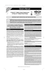
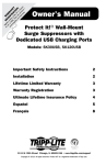
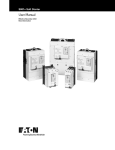
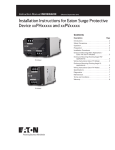
Instruction Manual IM00404002E
Effective January 2011
Surge TrapTM
CHSPT1
CHSP Type 1 Surge Protective Devices
Parasurtenseurs CHSP de Type 1
Dispositivos Supresores de Sobretensión
CHSP Tipo 1
Contents
Description
Page
Introduction. . . . . . . . . . . . . . . . . . . . . . . . . . . . . . 2
Installation and Operating Guide. . . . . . . . . . . . . . 2
Mounting. . . . . . . . . . . . . . . . . . . . . . . . . . . . . . 2
Conduit Installation . . . . . . . . . . . . . . . . . . . . . . 2
Wall Mounting. . . . . . . . . . . . . . . . . . . . . . . . . . 3
DIN Rail Mounting. . . . . . . . . . . . . . . . . . . . . . . 3
Wiring. . . . . . . . . . . . . . . . . . . . . . . . . . . . . . . . . 3
Specifications . . . . . . . . . . . . . . . . . . . . . . . . . . . . 4
Operation. . . . . . . . . . . . . . . . . . . . . . . . . . . . . . . . 4
Warranty . . . . . . . . . . . . . . . . . . . . . . . . . . . . . . . . 4
Introduction. . . . . . . . . . . . . . . . . . . . . . . . . . . . . . 2
Instructions d’installation et d’emploi. . . . . . . . . . 2
Montage. . . . . . . . . . . . . . . . . . . . . . . . . . . . . . . 2
Installation à travers un tube protecteur . . . . . . 2
Montage mural. . . . . . . . . . . . . . . . . . . . . . . . . . 3
Montage sur rail DIN. . . . . . . . . . . . . . . . . . . . . 3
Câblage . . . . . . . . . . . . . . . . . . . . . . . . . . . . . . . 3
Caractéristiques techniques . . . . . . . . . . . . . . . . . 4
Utilisation. . . . . . . . . . . . . . . . . . . . . . . . . . . . . . . . 4
Garantie. . . . . . . . . . . . . . . . . . . . . . . . . . . . . . . . . 4
Introducción. . . . . . . . . . . . . . . . . . . . . . . . . . . . . . 2
Guía de instalación y operación. . . . . . . . . . . . . . . 2
Montaje. . . . . . . . . . . . . . . . . . . . . . . . . . . . . . . 2
Instalación del conducto . . . . . . . . . . . . . . . . . . 2
Montaje en la pared. . . . . . . . . . . . . . . . . . . . . . 3
Montaje con riel DIN. . . . . . . . . . . . . . . . . . . . . 3
Cableado . . . . . . . . . . . . . . . . . . . . . . . . . . . . . . 3
Especificaciones . . . . . . . . . . . . . . . . . . . . . . . . . . 4
Operación . . . . . . . . . . . . . . . . . . . . . . . . . . . . . . . 4
Garantía. . . . . . . . . . . . . . . . . . . . . . . . . . . . . . . . . 4
CHSP Type 1 Surge Protective Devices

Instruction Manual IM00404002E
Effective January 2011
Introduction
Installation and Operating Guide
This manual describes how to install a Surge Protective Device
(SPD) in parallel (shunt) across the AC supply of the following
electrical systems:
• 120/240V, Single Split-Phase
Refer to Figure 1, and look at the label on the SPD to verify that the
SPDs voltage, rating, and wiring configuration matches that of the
electrical system.
•
120/208V, Three-Phase Wye
The SPD is designed to be installed on service entrance, branch
panels, and / or individual equipment disconnects, and functions to
protect the electrical system from damaging voltage transients.
The connecting wires do not carry supply current. Instead, they
carry only short-duration currents that are associated with a
transient event.
These instructions do not cover all details, variations, or
combinations of the equipment, its storage, delivery, installation,
checkout, safe operation, or maintenance. If you require further
information regarding a particular application or installation that is
not covered in this manual, please contact Eaton’s Power Quality
Technical Support at 1-800-809-2772, option 4, then select option 2.
Safety Precautions
A licensed / qualified electrician must complete all instructions
described in this manual in accordance with the U.S. National
Electrical Code, state and local codes, or other applicable country
codes. All electrical codes supersede these instructions.
Series
CHSPT1ULTRA
CHSPT1MAX
CHSPT1MICRO
CHSPT1-208Y
Figure 1. Catalog Numbering System
Use an AC voltmeter to measure the system’s line voltage to ensure
that the correct model of SPD is being installed. Damage to the SPD
may result if it is connected to an electrical system of a higher voltage or different wiring configuration.
Mounting
The SPD can be mounted directly to the electrical panel, or to a wall
or DIN rail with the addition of an optional mounting kit (accessory:
SP1DINRAILKIT).
warning! shock hazards
Improper installation can cause death, injury and / or
equipment damage. Follow all warning and cautions. Completely
read and understand the information in this instruction manual
before attempting to install or operate this equipment.
Improper wiring could cause death, injury, and / or equipment
damage. Only licensed / qualified electricians who are trained in the
installation and service of electrical devices are to install and service
this equipment.
Voltage Code
120/240V Single Split-Phase
120/240V Single Split-Phase
120/240V Single Split-Phase
120/208V Three-Phase Wye
important!
•
Choose a mounting location for the SPD that provides the
shortest and straightest possible wiring (lead length) from the
SPD to the electrical system connections. Excessive lead length
and sharp bends will degrade SPD performance.
•
When using conduit, avoid using 90º elbows and keep the conduit
run as short and straight as possible.
Use appropriate safety precautions and equipment for arc flash
protection.
Conduit Installation
During normal operation, hazardous voltages are present inside
the SPD.
Mount the SPD directly to the electrical panel using a ½” locknut as
shown in Figure 2.
When servicing the SPD, follow all safe work practices to avoid
electrical shock.
When mounting the SPD outdoors, use weatherproof conduit and
fittings to maintain the enclosure’s NEMA 4 rating. See Figure 3.
CAUTION!
Do not perform a high-pot test with the SPD connected to the
electrical system. Failure to disconnect the SPD during a high-pot
test will result in damage to the SPD.
Figure 2. Locknut Mounting with 1/2” Locknut / Montage avec
contre-écrou de ½ po / Montaje con tuerca de seguridad de ½
pulg.
2
eaton corporation www.eaton.com
Wall Mounting
Mount the SPD directly on a wall using the SPD’s optional bracket
(accessory: SP1DINRAILKIT) as follows:
1.Screw the provided wall bracket to the wall or other mounting
surface using two #10 screws of the appropriate type
(not provided) with the large hole in the bracket at the top.
Figure 3. Conduit Installation / Installation à travers un tube
protecteur / Instalación del conducto
CHSP Type 1 Surge Protective Devices

Instruction Manual IM00404002E
Effective January 2011
2.Thread the lead wires from the SPD through the large hole and insert the integrated hub into the large hole with the hub pointed upwards.
Operation
3.Use the locknut (provided) to secure the SPD hub to the bracket.
Apply system power. The LED should light.
DIN Rail Mounting
If the connected LED does not light, remove power, check
connections, and test again. If the LED still does not light, contact
Eaton’s power quality technical support at 1-800-809-2772, option 4,
then select option 2.
important!
•
Be sure to follow all U.S. National Electrical Code, state and local
codes, or other applicable country codes.
•
To avoid fire, shock, or death, turn OFF power at circuit breaker or
fuse and test that power is OFF before wiring.
•
When connecting the wires from the SPD to the electrical
system, cut the wires as necessary to keep them as short
as possible.
•
To maximize the SPD’s performance, twist and bind the wires
together to reduce the impedance of the wire (one twist / inch).
IMPORTANT!
1.Locate the electrical system’s applicable wiring diagram in Figure 5. Reference this wiring diagram as necessary in Steps 2 and 3.
2.Connect the SPDs neutral wire (white) to the system’s
neutral connection.
The device is not repairable and contains no user serviceable parts.
If the unit fails, as evidenced by the LED turning OFF, the unit must
be replaced.
PHASE A / PHASE A / FASE A
Split Phase
(240S)
Biphasé
(240S)
Fase dividida
(240S)
NEUTRAL
NEUTRE
NEUTRA
PHASE B
PHASE B
FASE B
Grounding and bonding per
national and local electrical codes
Mise à la terre et liaison
conformément aux codes
SPD
électriques nationaux et locaux
Puesta a tierra y vinculación de acuerdo
a los códigos eléctricos nacionales y locales
3.Connect the SPDs phase A, B, and C wires (black) to the
system’s corresponding phase A, B, and C connections according to applicable national, state, and locak electrical codes.
Phase A (BLK)
Wiring
With all phase voltages present, the LED indicator reports the status
of the protection elements and is active when all of them are intact
and providing protection. Any loss of protection is signaled when the
LED extinguishes.
Phase A (NOIR)
Fase A (NEGRA)
5.Snap the SPD and bracket to the DIN rail (not provided) with the hub pointed upwards.
Phase B (BLK)
4. Use the locknut (provided) to secure the SPD hub to the bracket.
After system power has been applied, the SPD automatically begins
to protect downstream electrical devices from damaging voltage
transients.
Phase B (NOIR)
Fase B (NEGRA)
3. Thread the lead wires from the SPD through the large hole in the bracket and insert the integrated hub into the large hole.
Routine Operation
Neutral (WHT)
2. Snap the DIN rail clip (provided) into the two smallest holes in the mounting bracket (provided).
Neutre (BLANC)
Neutra (BLANCA)
1. Attach the DIN rail clip (accessory: SP1DINRAILKIT) to the
bracket using the 3 screws (provided). See Figure 4.
Power Up and System Checkout
PHASE A / PHASE A / FASE A
PHASE B / PHASE B / FASE B
PHASE C / PHASE C
/ FASE C
NEUTRAL
NEUTRE
NEUTRA
3-Phase Wye
(208Y)
Phase A (BLK)
Phase A (NOIR)
Fase A (NEGRA)
Phase B (NOIR)
Fase B (NEGRA)
Phase B (BLK)
Phase C (BLK)
Phase C (BLANC)
Fase c (BLANCA)
Grounding and bonding per
national and local electrical codes
Neutral (WHT)
horqueta trifásica
(208Y)
Neutre (BLANC)
Neutra (BLANCA)
montage en
étoile triphasé
(208Y)
SPD
Mise à la terre et liaison
conformément aux codes
électriques nationaux et locaux
Puesta a tierra y vinculación de acuerdo
a los códigos eléctricos nacionales y locales
Figure 4. DIN Rail Mounting Kit / Kit de montage sur rail DIN /
Juego de montaje del riel DIN
Figure 5. SPD Wiring Diagram / Schéma de câblage du
parasurtenseur / Diagrama de cableado del SPD
eaton corporation www.eaton.com
3
CHSP Type 1 Surge Protective Devices

Instruction Manual IM00404002E
Effective January 2011
warning! shock hazards
DO NOT use the Suppression Circuit Status LEDs as an indication of the presence or absence of system phase voltages.
Warranty
2 Year Limited Product Warranty for CHSP Type 1
Surge Protective Devices.
Eaton Corporation (Eaton) warrants to the original retail purchaser
or user that the CHSP Type 1 Surge Protective Device will be free
from failure due to defects in workmanship or materials under normal care and proper usage in a residential or commercial installation
which fully complies with all National Electrical Code requirements
for 2 years from the purchase date subject to the terms below. In
the event of such a failure, Eaton will replace the product without
charge. See “To Submit A Warranty Claim” below.
NOTHING IN THIS LIMITED WARRANTY DOCUMENT AFFECTS
ANY STATUTORY RIGHTS OF CONSUMERS THAT CANNOT BE
WAIVED OR LIMITED BY CONTRACT. THIS WARRANTY GIVES
YOU SPECIFIC LEGAL RIGHTS, AND YOU MAY ALSO HAVE OTHER
RIGHTS WHICH VARY FROM JURISDICTION TO JURISDICTION.
This warranty is non-transferable and only applies to the original retail
purchaser or original user.
This warranty does not cover failure or damage due to an act of
God, normal wear, or improper storage, installation, operation, maintenance, accident, misuse, abuse or negligence of any party other
than Eaton. This warranty does not cover reimbursement for labor,
transportation, gaining access, removal, installation, temporary
power, or any other expenses which may be incurred in connection
with repair or replacement of the Unit. In no event shall Eaton be
liable for special, consequential, or incidental damages. THIS LIMITED WARRANTY IS THE EXCLUSIVE WARRANTY AND REPLACES
ALL OTHER WARRANTIES OR CONDITIONS, EXPRESS OR IMPLIED, INCLUDING, BUT NOT LIMITED TO, THE IMPLIED WARRANTIES OR CONDITIONS OF MERCHANTABILITY AND FITNESS FOR
A PARTICULAR PURPOSE. SOME STATES OR JURISDICTIONS DO
NOT ALLOW THE EXCLUSION OF EXPRESS OR IMPLIED WARRANTIES, SO THE ABOVE EXCLUSION MAY NOT APPLY TO YOU.
IN THAT EVENT, SUCH WARRANTIES ARE LIMITED IN DURATION
TO THE LIMITED WARRANTY PERIOD. SOME STATES OR JURISDICTIONS DO NOT ALLOW LIMITATIONS ON HOW LONG AN
IMPLIED WARRANTY LASTS OR THE EXCLUSION OR LIMITATION
OF INCIDENTAL OR CONSEQUENTIAL DAMAGES, SO THE ABOVE
LIMITATIONS AND/OR EXCLUSIONS MAY NOT APPLY TO YOU.
To Submit a Warranty Claim: Contact EatonCare
@ (1-877-ETN-CARE) option #2, option #1.
You will be requested to send, at minimum, the following
information:
a. Your full name.
b. Complete address including Zip (no PO boxes allowed).
c. A copy of the dated sales receipt.
d. A letter explaining the incident.
This Limited Warranty shall be governed by the laws of the state of
Pennsylvania, U.S.A.
Specifications
Table 1. SPD Specifications
Description
Ratings
Surge current capacity per phase
50kA CHSPT1ULTRA, 45kA CHSPT1MAX, 36kA CHSPT1MICRO, 50kA CHSPT1-208Y
Nominal Discharge Current (In)
20kA for all devices
Short-circuit current rating (SCCR)
200kA
SPD type
Type 1 (can also be used in Type 2 applications)
System voltages available (VAC)
120/240 single split-phase, 120/208 three-phase wye
Protection modes, single split-phase
L-N, L-L
Maximum continuous operating voltage (MCOV)
150 L-N, 300 L-L
Input power frequency
50/60 Hz
Enclosure rating
NEMA 4
Operating temperature
-20ºC through 50ºC (-4ºF through 122ºF)
Operating humidity
5% through 95%, noncondensing
Operating altitude
Up to 16,000 ft (5000 m)
Agency certification and approvals
UL1449 3rd Edition listed device
Limited Product Warranty
2 Years (see warranty section for more information)
4
eaton corporation www.eaton.com
CHSP Type 1 Surge Protective Devices

Instruction Manual IM00404002E
Effective January 2011
important!
Introduction
Cette notice d’emploi explique comment installer un parasurtenseur
en parallèle (en shunt) sur le circuit d’alimentation CA des installations électriques suivantes:
• 120/240 V, monophasé 3 fils
•
120/208V, Montage en étoile triphasé
Le parasurtenseur est conçu pour être installé à l’arrivée du circuit de service, dans les tableaux de branche et / ou dispositifs
de déconnexion des appareils individuels. Il protège le circuit électrique des tensions transitoires risquant de l’endommager. Les fils
de connexion ne conduisent pas de courant d’alimentation, mais
uniquement les courants de courte durée associés à un événement
transitoire.
Ces instructions ne couvrent pas tous les détails, variations ou combinaisons de l’équipement, son stockage, son transport, son installation ou sa vérification, ni les informations de sécurité ou d’entretien.
Si vous avez des questions sur une application ou installation particulière non traitée dans ce mode d’emploi, veuillez vous adresser au
service d’assistance technique Power Quality d’Eaton, au 1-800-8092772, option 4, puis option 2.
Consignes de sécurité
Toutes les instructions de ce manuel doivent être suivies par un
électricien qualifié / certifié, conformément au code électrique
national ou local. Tous les codes électriques ont prévalence sur
ces instructions.
AVERTISSEMENT! DANGERS D’ÉLECTROCUTION
Une mauvaise installation risque de provoquer des blessures
graves ou mortelles et / ou des dégâts matériels. Respectez
toutes les notices d’avertissement et de mise en garde. Lisez et
comprenez en intégralité les informations de cette notice d’emploi
avant d’installer ou d’utiliser cet appareil.
Un câblage incorrectement effectué risque de provoquer
des blessures graves ou mortelles et / ou des dégâts matériels.
Cet appareil ne doit être installé ou réparé que par un électricien
qualifié certifié, formé à l’installation et à la réparation des appareils
électriques.
Suivez des précautions de sécurité et utilisez un équipement
de protection appropriés contre les arcs électriques.
En fonctionnement normal, le parasurtenseur contient des
tensions dangereuses.
Lorsque vous réparez ce parasurtenseur, respectez toutes les
précautions de sécurité contre les électrocutions.
•
Choisissez un emplacement permettant un câblage (longueur
de fil) aussi court et rectiligne que possible entre le parasurtenseur et les bornes de l’installation électrique. Une longueur de fil
excessive et des coudes trop serrés diminuent les performances
du parasurtenseur.
•
Si vous utilisez un tube protecteur, évitez les coudes à angle droit
et gardez le tube aussi court et rectiligne que possible.
Installation à travers un tube protecteur
Montez le parasurtenseur directement sur le tableau électrique à
l’aide d’un contre-écrou de ½ po, comme illustré à la Figure 2.
Si vous montez le parasurtenseur à l’extérieur du bâtiment, utilisez
un tube protecteur et des raccords étanches afin de maintenir le
classement NEMA 4 du boîtier. Voir la Figure 3
Montage mural
Montez le parasurtenseur directement sur le mur à l’aide du support optionnel (réf. accessoire: SP1DINRAILKIT) en procédant de la
façon suivante:
1.Vissez le support mural fourni au mur ou sur une autre surface de montage, au moyen de deux vis n° 10 du type approprié (non fournies), en plaçant le trou le plus grand du support en haut.
2.Faites passer les fils du parasurtenseur dans le grand trou, et insérez le fût intégré à leur suite, en pointant celui-ci vers le haut.
3. Fixez le fût au support à l’aide du contre-écrou fourni.
Montage sur rail DIN
1. Fixez l’attache du rail DIN (réf. accessoire: SP1DINRAILKIT) sur le support, à l’aide des 3 vis (fournies). Voir la Figure 4.
2. Enclenchez l’attache du rail DIN (fournie) dans les deux petits trous du support de montage (fourni).
3. Faites passer les fils du parasurtenseur dans le grand trou du
support, et insérez le fût intégré à leur suite.
4. Fixez le fût au support à l’aide du contre-écrou (fourni).
5.Enclenchez le parasurtenseur et le support dans le rail DIN
(non fourni), en pointant le fût vers le haut.
Câblage
important!
•
Respectez le code électrique national ou local.
•
N’effectuez pas d’essai diélectrique lorsque le module est connecté
au circuit électrique. Ceci l’endommagerait.
Pour éviter un incendie, une électrocution ou un accident mortel,
coupez le courant au niveau du disjoncteur ou du fusible et
vérifiez l’absence de courant avant d’effectuer le câblage.
•
Lorsque vous connectez les fils du parasurtenseur au circuit
électrique, coupez-les à la longueur la plus courte possible.
Instructions d’installation et d’emploi
•
Pour de meilleures performances, tordez les fils l’un sur l’autre
afin de réduire l’impédance (une torsion tous les 2,5 cm).
MISE EN GARDE
Référez-vous au schéma 1, et regardez l’étiquette sur le SPD pour
vérifier que la tension de SPD, l’estimation, et la configuration de
câblage assortit cela du système électrique. Vérifiez la tension alternative de la ligne de courant à l’aide d’un voltmètre afin de vous
assurer que vous installez le bon modèle de parasurtenseur. Le parasurtenseur risque d’être endommagé s’il est connecté à un circuit
électrique de tension plus élevée ou de configuration de câblage
différente.
Montage
Le parasurtenseur peut être monté directement sur le tableau
électrique, ou sur un mur ou un rail DIN, au moyen du kit de
montage en option (réf. d’accessoire: SP1DINRAILKIT).
1.Localisez le diagramme de câblage applicable du système
électrique dans la figure 5. Mettez en référence ce diagramme de câblage selon les besoins dans les étapes 2 et 3.
2.Reliez le fil neutre de SPD (blanc) au système raccordement
neutre.
3.Reliez les SPD mettent des fils d’A, de B, et de C (noir) à la phase correspondante A du système, des raccordements en phase de B, et de C selon le national applicable, l’état, et les codes
électriques de locak.
eaton corporation www.eaton.com
5
CHSP Type 1 Surge Protective Devices

Instruction Manual IM00404002E
Effective January 2011
Utilisation
Mise sous tension et vérification
Mettez le système sous tension. Le voyant doit s’allumer.
Si le voyant connecté ne s’allume pas, coupez le courant, vérifiez
les connexions et réessayez. Si le voyant ne s’allume toujours pas,
contactez le service d’assistance technique Power Quality d’Eaton
au 1-800-809-2772, option 4, puis option 2.
Utilisation ordinaire
Une fois le courant allumé, le parasurtenseur commence automatiquement à protéger les appareils en aval contre les courants
transitoires risquant de les endommager.
Lorsque toutes les tensions de phase sont présentes, le voyant
indique l’état des éléments de protection et est allumé quand
ceux-ci sont tous intacts et opérationnels. L’éteinte du voyant
signale la perte de cette protection.
L’appareil n’est pas réparable et ne contient aucune pièce pouvant
être remplacée par l’utilisateur. Si l’appareil ne fonctionne plus (voyant éteint), il doit être remplacé.
AVERTISSEMENT! DANGERS D’ÉLECTROCUTION
NE VOUS FIEZ PAS AUX VOYANTS D’ÉTAT DES CIRCUITS DE COUPURE
POUR DÉDUIRE LA PRÉSENCE OU L’ABSENCE DE TENSIONS DE PHASE
DANS L’INSTALLATION.
Garantie
Garantie limitée de 2 ans sur les parasurtenseurs CHSP de
Type 1.
Eaton Corporation (Eaton) garantit à l’acheteur de détail ou
l’utilisateur d’origine que le parasurtenseur CHSP de Type 1 ne
présentera aucun vice de fabrication ou de matériau, dans des conditions normales d’utilisation et d’entretien, dans une installation résidentielle ou commerciale se conformant en tout point au code électrique national, et ce pour une période de 2 ans à partir de la date
d’achat, sous réserve des conditions ci-dessous. En cas de panne
couverte par la garantie, Eaton remplacera gratuitement le produit.
Voir « Comment faire appliquer la garantie » ci-dessous.
AUCUN ÉLÉMENT DE CETTE GARANTIE LIMITÉE N’AFFECTE
LES DROITS STATUTAIRES DES CONSOMMATEURS NE
POUVANT ÊTRE ANNULÉS OU LIMITÉS PAR CONTRAT. CETTE
GARANTIE VOUS CONFÈRE CERTAINS DROITS ET VOUS POUVEZ
ÉGALEMENT DISPOSER D’AUTRES DROITS SELON VOTRE
JURIDICTION.
Cette garantie n’est pas cessible et ne s’applique qu’à l’acheteur de
détail ou à l’utilisateur d’origine.
Cette garantie ne couvre pas les pannes ou dégâts provoqués par
un cas de force majeure, l’usure normale, des pratiques abusives
de stockage, d’installation, d’utilisation, de maintenance, un accident, un emploi abusif ou une négligence de la part d’un tiers autre
qu’Eaton. Cette garantie ne couvre pas le remboursement des frais
de main-d’œuvre, de transport, d’accès, de retrait, d’installation,
d’alimentation électrique provisoire, ou toute autre dépense occasionnée par la réparation ou le remplacement de l’unité. Eaton ne
saurait en aucun cas être tenu responsable de dommages directs
ou indirects. CETTE GARANTIE LIMITÉE EST EXCLUSIVE ET
REMPLACE TOUTE AUTRE GARANTIE OU CONDITION,
EXPRESSE OU IMPLICITE, Y COMPRIS, ENTRE AUTRES, TOUTE
GARANTIE OU CONDITION IMPLICITE DE VALEUR MARCHANDE
OU D’ADÉQUATION À UN USAGE PARTICULIER. CERTAINS ÉTATS
OU JURIDICTIONS INTERDISENT L’EXCLUSION DES GARANTIES
EXPRESSES OU IMPLICITES, ET L’EXCLUSION CI-DESSUS PEUT
NE PAS S’APPLIQUER À VOTRE CAS. LA DURÉE DE CES GARANTIES EST ALORS LIMITÉE À LA PÉRIODE DE GARANTIE LIMITÉE.
CERTAINS ÉTATS OU JURIDICTIONS INTERDISENT LA LIMITE
DE DURÉE DES GARANTIES EXPRESSES OU IMPLICITES, OU
L’EXCLUSION ET LA LIMITE DES DOMMAGES DIRECTS OU INDIRECTS, ET LES LIMITES ET/OU EXCLUSIONS CI-DESSUS PEUVENT
NE PAS S’APPLIQUER À VOTRE CAS
Comment faire appliquer la garantie: Contactez EatonCare à
(1-877-ETN-CARE), option 2, option 1.
Il vous sera demandé d’envoyer au minimum les informations
suivantes:
a. Votre nom en entier;
b. Votre adresse complète, y compris le code postal (pas de BP);
c. Le reçu de votre achat, avec la date;
d. Une lettre expliquant l’incident.
Cette garantie limitée est régie par les lois de l’État de la Pennsylvanie, États-Unis.
Caractéristiques techniques
Tableau 1. Caractéristiques techniques du parasurtenseur
Description
Classification
Capacité de courant de surtension par phase
50kA CHSPT1ULTRA, 45kA CHSPT1MAX, 36kA CHSPT1MICRO, 50kA CHSPT1-208Y
Courant de décharge nominal (ln)
20kA pour tous les appareils
Intensité de courant de court-circuit (Icc)
200kA
Type de parasurtenseur
Type 1 (peut aussi être utilisé dans les applications de Type 2)
Tensions de circuit disponibles (V CA)
120/240 seule dédoubler-phase, 120/208 montage en étoile triphasé
Modes de protection, monophasé à 3 fils
L-N, L-L
Tension de fonctionnement continu maximale (MCOV)
150 L-N, 300 L-L
Fréquence du courant d’alimentation
50/60 Hz
Classification du boîtier
NEMA 4
Température de fonctionnement
entre -20 ºC et 50 ºC
Humidité de fonctionnement
entre 5 % et 95 %, sans condensation
Altitude de fonctionnement
Jusqu’à 5 000 m
Homologations et certifications
Classé UL1449 3e édition
Garantie limitée
2 ans (voir la section de garantie pour plus d’information)
6
eaton corporation www.eaton.com
CHSP Type 1 Surge Protective Devices

Instruction Manual IM00404002E
Effective January 2011
importante!
Introducción
Este manual describe cómo instalar un dispositivo de protección
contra sobretensiones (SPD) en paralelo (derivación) a lo largo del
suministro de corriente CA del sistema eléctrico siguientes:
• 120/240 V, monofásico dividido
•
120/208V, Horqueta trifásica
El SPD ha sido diseñado para ser instalado en la entrada del servicio,
paneles de ramal y / o desconexiones individuales del equipo. Su
función es proteger al sistema eléctrico contra los transitorios de
tensión perjudiciales. Los cables de conexión no llevan corriente de
alimentación. En su lugar, sólo llevan corrientes de corta duración
relacionadas con un evento de transitorios de tensión.
Estas instrucciones no incluyen todos los detalles, variaciones o
combinaciones de equipo, su almacenamiento, entrega, instalación,
verificación, operación segura, ni el mantenimiento. Si necesita más
información acerca de una aplicación en particular o sobre la instalación, no incluidas en este manual, comuníquese con el departamento de Apoyo Técnico de Calidad de la Energía Eléctrica de Eaton
llamando al 1-800-809-2772, opción N.° 4, y enseguida seleccione la
opción N.° 2.
Precauciones de seguridad
Un electricista autorizado / calificado debe seguir las instrucciones
completas descritas en este manual de acuerdo con el Código de
Electricidad Estadounidense (U.S. National Electric Code), los códigos estatales y locales, u otros códigos nacionales que correspondan. Todos los códigos eléctricos sustituyen estas instrucciones.
ADVERTENCIA. PELIGRO DE DESCARGA
La instalación inadecuada puede provocar la muerte, lesiones y
/ o daño al equipo. Siga todas las advertencias y precauciones. Lea
y comprenda toda la información de este manual de instrucciones
antes de intentar instalar o poner en funcionamiento este equipo.
El cableado inadecuado puede provocar la muerte, lesiones
y / o daño al equipo. Este equipo debe ser instalado y reparado
únicamente por electricistas autorizados / calificados que estén
capacitados en la instalación y reparación de dispositivos eléctricos.
Utilice el equipo y las precauciones de seguridad correspondientes para la protección contra el relámpago de arco.
Durante el funcionamiento normal, hay tensiones peligrosas
dentro del SPD (dispositivo de protección contra sobretensiones).
Al reparar el SPD, siga todas las prácticas de seguridad para
evitar descargas eléctricas.
•
Elija un sitio de montaje para el SPD que brinde la posibilidad
de cableado más corta y recta posible (cable conductor) desde
el SPD hacia las conexiones del sistema eléctrico. Una longitud
excesiva del cable conductor y doblarlo demasiado afectan el
rendimiento del SPD.
•
Si utiliza un conducto, evite usar codos de 90° y procure que el
conducto sea tan corto y recto como sea posible.
Instalación del conducto
Monte el SPD directamente en el panel eléctrico con una tuerca de
seguridad de ½ pulg., tal y como se muestra en la Figura 2.
Si monta el SPD en exteriores, utilice un conducto y accesorios
resistentes a la intemperie para conservar la clasificación NEMA 4
de la caja eléctrica. Consulte la Figura 3.
Montaje en la pared
Monte el SPD directamente en una pared usando el soporte
opcional del SPD (accesorio: SP1DINRAILKIT) como se muestra
a continuación:
1.Atornille el soporte que se incluye en la pared o en otra superficie de montaje con dos tornillos N.° 10 del tipo adecuado (no
incluidos), colocando el orificio grande del soporte en la parte superior.
2.Pase los cables conductores del SPD a través del orificio grande
e inserte el cubo integrado en el orificio grande, con el cubo mirando hacia arriba.
3.Asegure el cubo del SPD al soporte con la tuerca de seguridad (incluida).
Montaje con riel DIN
1. Fije el sujetador del riel DIN (accesorio: SP1DINRAILKIT) al
soporte con los 3 tornillos (incluidos). Consulte la Figura 4.
2. Fije el sujetador del riel DIN (incluido) a presión en los dos orificios
más pequeños del soporte de montaje (incluido).
3. Pase los cables conductores del SPD a través del orificio grande del soporte e inserte el cubo integrado en el orificio grande.
4. Asegure el cubo del SPD al soporte con la tuerca de seguridad (incluida).
5.Fije el SPD y el soporte a presión en el riel DIN (no incluido) con el cubo mirando hacia arriba.
Cableado
importante!
PRECAUCIÓN
No realice una prueba de sobretensión (Hi-Pot) con el SPD conectado al sistema eléctrico. Si no desconecta el SPD durante una prueba
de sobretensión, se dañará.
Guía de instalación y operación
Refiera al cuadro 1, y mire la etiqueta en el SPD para verificar que el
voltaje de los SPD, el grado, y la configuración del cableado empareja el del sistema eléctrico. Utilice un voltímetro de CA para medir la
tensión de la línea del sistema para garantizar que está instalando el
modelo de SPD correcto. El SPD puede sufrir daños si se conecta a
un sistema eléctrico con una tensión mayor o con una configuración
de cableado diferente.
•
Asegúrese de seguir las instrucciones del Código de Electricidad
Estadounidense (U.S. National Electrical Code), los códigos
estatales y locales, u otros códigos nacionales que correspondan.
•
Para evitar incendios, descargas eléctricas o la muerte, apague el
interruptor de circuito o el fusible y pruebe que la corriente esté
desconectada antes de proceder con el cableado.
•
Antes de conectar los cables del SPD al sistema eléctrico, córtelos del tamaño necesario para que queden lo más cortos posibles.
•
Para optimizar el rendimiento del SPD, tuerza y una los cables juntos para disminuir la impedancia del cable (una vuelta por pulgada
[2.54 cm]).
Montaje
TEl SPD puede montarse directamente en el panel eléctrico, o en
una pared o riel DIN con la ayuda de un equipo de montaje opcional
(accesorio: SP1DINRAILKIT).
eaton corporation www.eaton.com
7
Instruction Manual IM00404002E
Effective January 2011
1.Localice el esquema eléctrico aplicable del sistema eléctrico en el cuadro 5. referencia este esquema eléctrico cuanto sea necesario en los pasos 2 y 3.
2.Conecte el alambre neutral de los SPD (blanco) con la conexión neutral del sistema.
3.Conecte los SPD ponen en fase los alambres de A, de B, y de C (negro) a la fase correspondiente A del sistema, las conexiones de B, y de C según nacional aplicable, estado, y códigos
eléctricos del locak.
Operación
Encendido y verificación del sistema
Energice el sistema. El indicador LED debe encenderse.
Si el indicador LED conectado no se enciende, corte la corriente
eléctrica, verifique las conexiones y vuelve a probar. Si aun así el
indicador LED todavía no se enciende, comuníquese con el departamento de Apoyo Técnico de Calidad de Energía Eléctrica de Eaton
llamando al 1-800-809-2772, opción N.° 4, y enseguida seleccione la
opción N.° 2.
Operación de rutina
Después de energizar el sistema, el SPD comienza automáticamente
a proteger los dispositivos eléctricos instalados en una ubicación
posterior a este dispositivo contra transitorios de tensión perjudiciales.
Con todas las fases de tensión presentes, el indicador LED informa
acerca del estado de protección de los elementos y se mantiene
activado cuando todos ellos están intactos y ofreciendo protección.
Cuando el indicador LED se apaga, señala cualquier pérdida de
protección del sistema.
Este dispositivo no se puede reparar y no contiene piezas que
requieren servicio por parte del usuario. Si la unidad falla, lo cual
es evidente cuando el indicador LED se apaga, ésta debe ser
reemplazada.
ADVERTENCIA. PELIGRO DE DESCARGA
NO UTILICE LOS INDICADORES LED DE SUPRESIÓN DE ESTADO DEL
CIRCUITO COMO INDICACIÓN DE LA PRESENCIA O AUSENCIA DE FASES
DE TENSIÓN DEL SISTEMA.
Garantía
Garantía limitada del producto por 2 años para dispositivos
supresores de sobretensión CHSP Tipo 1.
Eaton Corporation (Eaton) garantiza al comprador por menor original
o al usuario original que el dispositivo supresor de sobretensión
CHSP Tipo 1 estará libre de defectos de mano de obra o de materiales si se lo somete a cuidado normal y al uso adecuado en una
instalación residencial o comercial que cumple todos los requisitos
CHSP Type 1 Surge Protective Devices

del Código de Electricidad Estadounidense (National Electrical Code)
durante 2 años a partir de la fecha de compra, sujeto a los siguientes
términos. En caso de que se produzca una falla de ese tipo, Eaton
reemplazará el producto sin cargo. Consulte “Para presentar un reclamo de garantía”, más abajo.
NADA DE LO ESTABLECIDO EN ESTE DOCUMENTO DE GARANTÍA
LIMITADA AFECTA LOS DERECHOS DE LOS CONSUMIDORES
ESTABLECIDOS POR LA LEY QUE NO PUEDEN ANULARSE
NI LIMITARSE POR CONTRATO. ESTA GARANTÍA LE BRINDA
DERECHOS LEGALES ESPECÍFICOS Y ES POSIBLE QUE TAMBIÉN
TENGA OTROS DERECHOS QUE VARÍAN DE UNA JURISDICCIÓN
A OTRA.
Esta garantía es no transferible y se aplica sólo al comprador por
menor original o al usuario original.
Esta garantía no cubre fallas o daños que sean producto de fuerza
mayor, desgaste normal, o almacenamiento, instalación, operación o
mantenimiento inadecuados, accidente, uso inadecuado, maltrato o
negligencia de cualquier otra parte que no sea Eaton. Esta garantía
no cubre reembolsos por mano de obra, transporte, acceso, extracción, instalación, alimentación temporaria o cualquier otro gasto en
el que se puede haber incurrido en relación con la reparación o el
reemplazo de la Unidad. En ningún caso Eaton se responsabilizará
por daños especiales, indirectos o fortuitos. ESTA GARANTÍA LIMITADA ES LA GARANTÍA EXCLUSIVA Y REEMPLAZA A TODAS LAS
DEMÁS GARANTÍAS O CONDICIONES, EXPRESAS O IMPLÍCITAS,
INCLUIDAS, ENTRE OTRAS, LAS GARANTÍAS O CONDICIONES
IMPLÍCITAS DE COMERCIABILIDAD Y ADAPTABILIDAD PARA UN
FIN DETERMINADO. ALGUNOS ESTADOS O JURISDICCIONES
NO PERMITEN LA EXCLUSIÓN DE GARANTÍAS EXPRESAS O
IMPLÍCITAS; POR LO TANTO, ES POSIBLE QUE LA EXCLUSIÓN
ANTERIOR NO SE APLIQUE A SU CASO. EN ESE CASO, DICHAS
GARANTÍAS ESTÁN LIMITADAS EN SU DURACIÓN AL PERÍODO DE
LA GARANTÍA LIMITADA. ALGUNOS ESTADOS O JURISDICCIONES
NO PERMITEN LIMITACIONES EN EL TIEMPO QUE DURA UNA
GARANTÍA IMPLÍCITA O LA EXCLUSIÓN O LIMITACIÓN DE DAÑOS
INDIRECTOS O FORTUITOS; POR LO TANTO, ES POSIBLE QUE LAS
LIMITACIONES Y/O EXCLUSIONES ANTERIORES NO SE APLIQUEN
A SU CASO.
Para presentar un reclamo de garantía: Comuníquese con
EatonCare a través del (1-877-ETN-CARE) opción N.° 2, opción N.° 1.
Se le solicitará que envíe, como mínimo, la siguiente información:
a. Nombre completo.
b. Dirección completa, incluido el código postal (no se admiten
apartados postales).
c. Una copia del recibo de venta, con fecha.
d. Una carta que explique el incidente.
Esta Garantía limitada se regirá por las leyes del estado de
Pensilvania, EE. UU.
Complete Home Surge Protection


Instruction
Manual IM00404002E
Effective January 2011
Especificaciones
Tabla 1. Especificaciones del SPD
Descripción
Calificaciones
Capacidad de sobrecorriente por fase
50kA CHSPT1ULTRA, 45kA CHSPT1MAX, 36kA CHSPT1MICRO, 50kA CHSPT1-208Y
Corriente de descarga nominal (ln)
20kA para todos los dispositivos
Corriente nominal de corto circuito (SCCR)
200kA
Tipo de SPD
Tipo 1 (también puede utilizarse en aplicaciones Tipo 2)
Tensión de sistema disponible (VCA)
120/240 sola partir-fase, 120/208 horqueta trifásica
Modos de protección, monofásico dividido
L-N, L-L
Tensión de trabajo continua máxima (MCOV)
150 L-N, 300 L-L
Frecuencia de energía de entrada
50/60 Hz
Clasificación de caja eléctrica
NEMA 4
Temperatura de operación
-20°C hasta 50°C (-4°F hasta 122°F)
Humedad de operación
5% hasta 95%, sin condensación
Altitud operacional
Hasta 16,000 pies (5,000 m)
Certificación y aprobaciones de agencias
Dispositivo aprobado por UL1449, 3a edición
Garantía limitada del producto
2 años (vea la sección de la garantía para más información)
Eaton Corporation
Electrical Sector
1000 Cherrington Parkway
Moon Township, PA 15108
United States
877-ETN-CARE (877-386-2273)
Eaton.com
© 2010 Eaton Corporation
All Rights Reserved
Printed in USA
Publication No. IM00404002E / VCG105
January 2011
PowerChain Management is a registered
trademark of Eaton Corporation.
All other trademarks are property of their
respective owners.