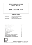
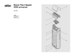
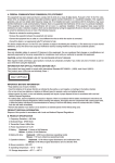
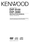
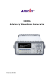
1
80486SXm20/25/40 M H zd’-;;t ~~~~ ‘2j
80486DX-33/50 M H Z
80486DX2-50/66 M H Z
(E 3486)
USER’S MANUAL
,
386 chip
UP
grade 486TM
PREPARATION OF YOUR MAINBOARD
SYSTEM ASSEMBLY
SYSTEM BIOS SETUP
APPENDIX
- 1 -
/PREPARATION OFYOUR MAINBOARD .
INTRODUCTION
Congradulations on your procurement of the EFAR-3486 mainboard.
you are now the owner of one of the most powerful flexible and
upgradable IBM PC AT compatible mainboards in the market.
The 3486 mainboard which employed EFAR-8290WB chipset has passed
strict quality control procedure to ensure high degree of reliability and
compatibility.
This mainboard is so designed to allow the flexibility of using any of the
386 and 486 CPUs exist in today’s PC market, depending on the need of
a user.
This feature of flexibility is achieved by using the EFAR-8290WB
chipset, which integrates several components into three sophisticated
Asic (application Specific Integrated Circuits) designs.
The chipset consitst of three chips:
* The 82EC495 System Controller (SC)
* The 82EC392 Data Buffer Controller (DBC)
* The 82C206 Integrated Peripheral Controller (IPC)
Product data and specification information as contained in this manual
are subject to change without prior notice for the sake of technical
improvement in performance and reliability, since we are permanently
endeavoring to supply the best products possible.
The manufacturer does not assume responsibility for customer product
designs and for the fitness to any particular application, nor for patent
rights or other rights of third parties and infringements there of resulting
from the use of this product.
- 2 -
The information furnished by us is believed to be accurate and reliable.
However, no responsibility is assumed for inaccuracies that may not have
been detected prior to printing, and for those which occur beyond our
control.
This document may not, in whole or part be copied, photocopied,
reproduced, translated, or converted to any machine readable form
without prior written consent of the publisher.
This manual uses the following trademarks:
l
IBM,IBM/PC,PC/AT are registered trademarks of International
Business Machine Corporation.
0
Intel and 386 are the registered trademarks of Intel Corporation.
0
Weitek is a registered trademark of Weitek Corporation.
l
Xenix is a registered trademark of the Santa Cruz Corperation.
0
Novell is a registered trademark of Novell Corp.
l
Unix is a rgeistered trademark of AT & T.
l
3Com is a registered trademark of 3Com Corporation.
l
EFAR is a registered trademark of EFAR Microsystems, Inc.
All product names mentioned in this manual and not listed above are the
registered trademarks of their respective companies.
- 3 -
E3486 Mainboard
PREPARATION OF YOUR
MAINBOARD
l
Features
l
Jumper Setting
l
Connector Pinouts
l
CPU Installation
l
Math.Coprocessor Installation
l
Memory Installation and Configuration
l
Cache Memory Installation
- 4 -
FEATURES
FEATURES
The Significant Features of E 3486 Cache Mainboard.
Can be used with any of the following CPUs:
Intel 80386 DX-2533
AMD 80386 DX-40
Intel 80486 SX-20,25
Intel 80486 DX-33,50
Intel 80486 DX2-50
Intel 80486 DXZ-66
AMD 80486 SX-40
Support Coprocessor (Weitek 3167 or, Intel
synchronous
EFAR EF8290WB Chipset
Support g-bit ROM BIOS
Write-Back Direct Mapped Cache
Support 64K, 256K Cache Memory Size
Support Shadow RAM for System and Video BIOS
Page mode operation on any banks
Fast Gate A20 and Reset Support
DRAM parameters can be optimized via wait states
Legal AM1 BIOS with built-in setup utilities
l
Support 1 to 32MB on-board
Supports 256K/lM/4M DRAM (SIMM)
- 5 -
80387 optional)
FEATURES
l
l
l
l
l
l
l
l
Support mix DRAM types on different banks
8 Expansion Slots (two &bit & Six 16-bit)
(synchronous Bus Clock)
D i s p l a y M o d e supported:8514/A,VGA,EGA,CGA,MDA,
Hercules
and
Operation System supported:MS DOS, OS/a, DR DOS, XENIX, and
UNIX
Network supported:Novell, 3Com, and D-Link
Dual speed selectable via keyboard, software or hardware Turbo
Switch
On-board Real Time Clock/Calendar with rechargeable-battery
On-board power good logic, active reset circuitries for stable power-on
and power-off operations
- 6 -
JUMPER SEITING
The motherboard upgrade feature from 386DX to
486SX/DX processor is accomplished with as few
jumper settings. In addition, there are
as 8 (eight)
1
s t a n d a r d m o t h e r b Q a r d qonfiguration
jumpers for memory and accessory settings. The
the
following tables identify
required.
the motherboard jumpers
1 JUMPER 1 IPOSITION
-II
I
JPl
I
JP2
II
l-2
II
3-4
El
JP3,
487s~
486dx
486s~
JP4
I
486sx
487sx,486dx
pq
64x
256x
386dx
486dx
386dx
486dx
386dx
486dx
JP13
II
l-2
2-3
I
386dx
486dx
JUMPERSETTING
.
- 8 -
CONNECTOR PINOUTS
CONNECTOR PINOUTS
Power Supply Connector (517,518).
Pin
Description
1
Power Good
2
+5 Vdc
3
+ 12 Vdc
4
- 12 Vdc
5
Ground
6
Ground
7
Ground
8
Ground
9
-5 V d c
10
+5 Vdc
11
+5 Vdc
12
+5 Vdc
Keyboard Connector (520)
They keyboard cable connects to the system board through a Spin din
connector.
The following table lists the connector pins and their signal names.
Pin
Description
1
Keyboard Clock
2
Keyboard Data
3 ’
Keyboard Reset
4
5
.
Ground
+5 Vdc
- 9 -
CONNECTOR PINOUTS
Speaker Connector (Jl)
This is a 4-pin header.
Pin
Description
1
Speaker Signal
2
+5 Vdc
3
Groung
4
+5 Vdc
Keylock and Front Panel Power LED Connector (J2)
This is a Spin header.
Pin
Description
1
LED Power
2
4
Not used
Ground
Keyboard inhibit
5
Ground
3
l
External Battery Connector (519)
This is a 4-pin header.
Pin
Description
1
+6 Vdc
Not used
Ground
- 10 -
. I
CONNECTOR PINOUTS
Ia c
:’
0
a
0
.
Y
;
1
0
r
ACTION
1
SPEAKER
EXTERNAL
1
BATTERY
NORMAL OPER4’I‘ION
SYSTEM RESE’I’
- 11 -
TURBO DISABLE
TURBO ENABLE
CPU INSTALLATION
The E3486 Mainboard provides sockets for any 386DX, 486SX, 486DX
and 4861)X2. CPU’s exist in today’s PC Market. However, only one
CPU Can be installed on the Mainboard, and the corresponding
oscillator must be used properly. The following table shows the jumper
settings and oscillator which must be used when a particular CPU is
installed.
II
I
I n t e l 386DX-33
I
JUMPER SE’ITING(JP11)
OSCILLATOR
1-2
50MHZ
1-2
66.667MHZ
l-2
80MHZ
l-2
40MHZ
I n t e l 486SX-25
l-2
I n t e l 3861)X-33
l-2
66.667MHZ
I n t e l 486DX-50
2-3
50MHZ
I n t e l 4861)X2-50
l-2
Intel 486DX2- 66
l-2
- 12 -
I
b1
50MHZ
SOMHZ
66.667MHZ
I
I
MATH CO-PROCESSOK 1NSTALLATION
Plug your Math Co-Processor Into the socket as Shown in the figure.
(Intel 80387 or weitek 3167) NO jumper setting is required.
However,proper BIOS setting is necessary.
- 13 -
MEMORY INSTALLION & CONFIGNATION
Eight SIMM sockets are available on the mainboard. The eights SIMM
sockets are arranged into 2 banks; Bank 0 (U40-U43) and Bank 1 (U44-U
47) with a minimum memory configuration of IMB. (ie.4 memory
modules of 256k bv 9 bit occupying bank 0).
A Memory Configuration Table for other memory size listed is as follows
Memory Configurafion Table
BANK 0
TOTAL
BANK 1
MEMORY SIZE
(BYTES)
1M
2M
I
X
256K x 9,4 PCS1
256K x 9,4 PCS
1M x 9,4 PCS
4M
5M
I
8M
r
256K x 9,4 PCS
I
X
256K x 9,4 PCS1
1M x 9,4 PCS
lMx9,4PCSl
lMx9,4PCS
16M
4M x 9,4 PCS
20M
1M x 9,4 PCS
20M
4M x 9,4 PCS
1M x 9,4 PCS
32M
4Mx9,4PCSl
4Mx9,4PCS
Remarks: 1.
X
I
I
4M x 9,4 PCS
70ns DRAM is recommended.
‘1. 256Kx9=256KB SIMM RAM Module.
lMxS=lMB SIMM RAM Module.
EMS Emulator
A software EMS emulator is necessary to make use of the expanded
memory. Many software EMS emulators are available in the market,
contact your dealer for more information.
- 14 -
0 XNV8
L,
I
Ln
I
NOIUSOd WUS
CACHE MEMORY INSTALLATION
The 3486 Mainboard provides options of 64KB’Cache or 256KB Cache
memory for performance improvement. The location to install SRAM
chips is shown in the figure. Use the proper combination of TAG RAM,
SRAM and Jumper Settings to achieve desired cache size for your
mainboard.
Cache and Tag Ram jumpers:
NOTE
Any damage caused to the 3486 M/B due to incorrect
installation procedures will invalidate all warranties.
- 16 -
CACHE MEMORY INSTALLATION
.
I
I
I
I
- 17 -
I
I
I
E3486 Mainboard
-I
SYSTEM ASSEMBLY
l
Installation in the System Case
l
Connecting the Power Supply
l
Connection the Keyboard
0 Installing Interface Cards
l
Power-On
- 18 -
SYSTEM ASSEMBLY
Introduction
The E3486 Mainboard can be installed in most cases designed for AT
compatible mainboards including “baby” AT sized cases. The actual
dimensions of the board are 22cm wide and 33cm long. There are several
mounting holes on the board which should allow you to mount the board
no matter what kind of case you are using.
Installation in the System Case
When you install the E3486 Mainboard in your case, make sure it is
correctly oriented with the interface card slots to the rear and the
keyboard connector on the right as you face the front of your system case
Depending on the design of your case, the mainboard will be fixed in
place either by plastic studs which can be inserted through the mounting
holes from the bottom, or by screws which should be inserted through the
mounting holes from the top. If screws are used, make sure each screw is
fitted with a non-conductive washer to prevent any shorting on your
mainboard.
With some cases, particularly those of compact design, it may be
necessary to remove the power supply and/or disk drive housings. The
procedure for doing this will vary from case to case, though it is usually a
simple matter of removing a few screws. Please consult any instructions
included with your system case for details. Under no circumstances bend
the board or try to force it into place. Taking an extra five minutes to
remove components if necessary is a far better solution than ending up
with a cracked or damaged board which may well malfunction or fail to
operate cmomletely. If you are in any doube as to how the 3486
Mainboard should be installed please consult a professional technician.
- 19 -
SYSTEM ASSEMBLY
Connecting the Power Supply
The connector for the power supply is situated near the keyboard socket
on the 3486 Mainboard. The connector is a standard AT switching power
supply type, and you should be able to plug the leads from your power
supply directly into this connector. Ideally, a power supply of at leaast
200 watts capacity should be used, especially if you have a hard disk
drive installed in your system. Most standard AT compatible power
supplies are ideal for tha 3486 Mainboard.
Connecting the Keyboard
The 3486 Mainboard comes with a keyboard socket built on to the board
next to the power supply connector. After the 3486 Mainboard has been
installed in your computer case, you can plug your keyboard directly into
this socket from the rear of your computer case. Note that an AT
compatible keyboard must be used with the 3486 Mainboard. An XT
compatible keyboard will not work.
Installing Interface Cards
The 3486 Mainboard has six AT (16-bit) slots, two XT (g-bit) slot. AT
type (16-bit) interface cards have a single edge connector. XT interface
cards may be installed in AT type slots by simply plugging the single
card connector in the longer slot. AT interface cards may not be installed
in the XT interface card slot.
When you install full length interface cards ensure that the card is
correctly fitted into the guides at the front and back of your case and
push the card firmly into the slot. You do not need to use the slots in any
particular order. Any empty slot may be used to install any kind of
interface card.
Power-ON
When you have installed the 3486 Mainboard in your case, check that
you have carried out the following operations before turning on your
comprter:
- 20 -
SYSTEM ASSEMBLY,
1.
2.
Correctly set all jumper switches on the 3486 Mainboard according
to the configuration of your system.
Connected a13 jumpers from the components on your system case,
including power-on LED and keylock, reset switch, turbo switch,
turbo LED and speaker.
3.
Connected a power supply of the correct voltage and power output
(at least 200 watts).
4.
Installed a video graphics adapter such as an MGA, CGA, EGA or
VGA card depending on the type of monitor you wish to use, into
any empty slot.
5.
Closed your computer case and connected the monitor to the back of
the video graphics adapter.
6.
Connected your keyboard to the keyboa rd connector on the 3486 M/
B through the back of your system case.
Tf
you have carried out all the steps above, you may turn on your
computer and use the SETUP program in the BIOS on your 3486
Mainboard to configure the board to your hardware requirements. For
details on how to use the SETUP program refer to the following section.
*A
If your computer fails to boot at power-on and you hear a number of
“beeps”,this probably means that you have forgotten to install a vital
component, such as the video adapter or disk drive control card, or made
a wrong connection. Check all the jumper settings you have made and
ensure that they correspond to the actual configuration of the 3486 M/B.
Also,, recheck all connections before trying again. In particular, check
the connections from your disk drive(s) to the disk drive control card.
Disk drive cables have one colored edge, usually red, indicating Line 1 .
The colored edge must be matched to Pin 1 of the connector on your disk
drive control card and the disk drive.
If you are still having
problems after thoroughly checking your system
4
configuration, please consult the dealer from whom you purchased the
3486 Mainboard.
- 21 -
c
E3486 Mainboard
SYSTEM BIOS S E T U P
l
AM1 BIOS Register Setup
l
Standard CMOS Setup
l
Advanced CMOS Setup
l
Auto Configuration
l
Auto Configuration With Power-On Detaults
l
Change Password
l
Write To CMOS And Exit
- 22 -
.
SYSTEM BIOS SETUP
This chapter tells the user how to use the SETUP for 3486 mainboard.
Please note that any improper use of this setup can cause damage to your
system. Therefore please make sure you understand thoroughly before
making any change or you may contact your dealer for more detailed
information.
This chapter will describe briefly the BIOS written by AMI. (American
Megatrendlnc.) In the mean time do not use other BIOS than the one
uses in this board as it will cause functional incompatibility.
AM1 BIOS Register Setup
The setup program is used to configure the system. These system options
are stored in the CMOS. If the CMOS is good, the system is configured
with the values stored in the CMOS. If the CMOS is bad, the system is
configured with the default values stored in the ROM file. There are 2
sets of BIOS values stored in the ROM file: the BIOS Setup default
values and the Power-On default values.
The BIOS Setup default values are the default values which should
provide optimum performance for the system. They are the best case
default values.
The Power-On default values, which are the worst case defaults, are
the stable values for the system. They are to be used if the system is
performing erratically because of hardware problems.
Listed below is an explanation of the keys displayed at the bottom of the
screens accessed through the BIOS SETUP program:
ESC:Exit to previous screen.
Arrow keys: Use arrow keys (t--+ J+-) to move cursor to desired selection
- 23 -
.
!
SYSTEM BIOS SETUP
PgUp/PgDn/Ctrl-PgUp/Ctrl-PgDn:Modify the default value of the
options for the highighted feature. If there are less than 10 available
options, the Ctrl-PgUp and Ctrl-PgDn keys function the same as the
PgUp and PgDn keys.
Fl:Displays help screen for selected feature.
FZ/F3: Change background and foreground colors.
F5:Retrieves the values which were resident when current setup session
was started. These values will be CMOS values if the CMOS was
uncorrupted at the start of the session, or they will be the BIOS Setup
default values.
F6:Loads all features in the Advanced CMOS Setup/Advanced Chipset
Setup with the BIOS Setup defaults.
F7:Loads all features in the Advanced CMOS Setup/Advanced Chipset
Setup with the Povirer-On defaults.
1
-1
FlO:Saves all changes made to Setup ana exits program.
Note:The defaults value for the prompts which occur when the <F5>,
<F6>,and <F7> keys are pressed is always <N> (No.) Actually
executing these options requires changing the <N > to <Y > (Yes) and
pressing < ENTER > .
BIOS SETUP PROGRAM - AMIBIOS SETUP UTILITIES
(C) 1991 American Megatrends Inc., All Rights Reserved
STANDARD CMOS SETUP
ADVANCED CMOS SETUP
ADVANCED CHIPSET SETUP
AUTO CONFIGURATION WITH BIOS DEFAULTS
AUTO CONFIGURATION WITH POWER-ON DEFAULTS
CHANGE PASSWORD
HARD DISK UTILITY
WRITE TO CMOS AND EXIT
DO NOT WRITE TO CMOS AND EXIT
Standard CMOS Setup for Changing Time, Date, Hard Disk Type, etc.
ESC:Exit _1+tSel F2/F3:Color FlO:Save & Exit W’
- 24 -
.
.
Standard CMOS Setup
The Standard CMOS Setup utility is used to configure the following
features:
Date:Month, Date, and Year. Ranges for each value are listed below in
prompt box in the lower right corner of the CMOS Setup Screen.
Time:Hour, Minute, and Second. Uses 24 hours format.
Daylight Savings:Disbaled or Enabled.
Hard Disk C and Hard Disk D:Hard disk types from 1 to 46 are
standard ones; type 47 is user definable. The user must enter the hard
disk parameters for each drive.
t
The drive types are identified by the following characteristics:
Type
The number designation for a drive with certain identification
parameters.
CYl
The number of cylinders found in the specified drive type.
Heads.
The number of heads found in the specified drive type.
Wpcom The read delay circuitry which takes into account the timing
- 25 -
Standard CMOS Setup
-
-
differences between the inner and outer edges of the surface of
the disk platter. The number designates the starting cylinder of
the signal.
L-zone L-zone is the landing zone of the heads. This number
determines the cylinder location where the heads will normally
park when the system is shut down.
Capacity The formatted capacity of the drive based on the formula:
(NUMBER of heads)x(NUMBER of cylinders)x(NUMBER
of secs/cyl.)x(512bytes/sec)
“Not Installed” is available for use as an option. This option
could be used for diskless workstations and SCSI hard disk.
Type 47 may be used for both hard disks C and D. The
parameters for type 47 under Hard Disk C and Hard Disk D
may be different.
Floppy Drive A and Floppy Drive B:The options are 360KB 5 $ “,1.2
MB 5i” ,720 KB 3 ii “,1.44 MB 3 + “, and Not Installed. Not installed
could be used as an option for diskless workstations.
Primary Dispaly:Options are Monochrome, Color 40x25,
VGA/PGA/EGA, Color 80x25, and Not Installed. The Not Installed
option could be used for network file servers.
Keyboard:Options are Installed or Not Installed.
The advanced CMOS Setup program is equipped with a series of help
screens, accessed by the <Fl> key, which will display the options
available for a particular configuration feature and special help for some
of the options.
The following is a short description for each of the options on the
Advanced CMOS Setup Screen.
- 26 -
Standard CMOS Setup
Above 1 MB Memory Test:This feature, when enabled, will invoke the
POST memory routines on the RAM above 1 MB (if present on system).
If disabled, the BIOS will nly check the first 1 MB of RAM.
Memory Test Tick Sound:This option will enable (turn on) or disable
(turn off) the “ticking” sound during the memory test.
Memory Parity Error Check:If the motherboard doesn’t have parity
RAM, user may disable the memory parity error checking routines in the
BIOS.
Hit <DEL> Message Display:Disabling this option, will present the
message:
“Hit <DEL> if you want to run SETUP”
displaying on the screen when the system boots-up.
Hard Disk Type 47 RAM Area:The AMIBIOS SETUP features two
userdefinable hard disk types. Normally, the data for these disk types are
stored at 0:300 in lower system RAM. If a problem occurs with other
software, this data can be located at the upper limit of the DOS Shell
(640 KB). If the option is set to DOS 1 KB,the DOS Shell is shortened to
639 KB, and the top KB is used for the hard disk data storage.
Wait For <Fl> If Any Error:Before the system boots-up, the BIOS
will execute the POST routines, a series of system diagnostic routines. If
any of these tests fail, but a non-fatal error has occurred and the system
can still function, the BIOS will respond with an appropriate error
message followed by the following statement:
“Press<Fl> to continue”
If this option is disabled, any non-fatal error which occurs will not
generate the above statement, but the BIOS will still display the
appropriate error message. This will eliminate the need for any user
response to a non-fatal error condition message.
- 27 -
Standard CMOS Setup
System Boot Up Num Lock:The user may turn off the ‘Num
Lock”option on his Enhanced Keyboard when the system is powered on.
This will allow him to use the arrow keys on the numeric keypad instead
of using the other set of arrow keys on the Enhanced Keyboard. The
BIOS will default to turning the “Num Lock”on.
Floppy Drive Seek At Boot:The default for this option is “Disabled”
to allow a fast boot and to reduce the possibility of damage to the heads.
System Boot Up Sequence:The AM1 BIOS will default to boot from
floppy drive A: (if present), and if unsuccessful, it will boot from hard
disk C:.
Cache Memory:This option allows user to specify whether the external
cache is enable or disable.
Internal Cache Memory:This option allows user to enable or disable
the internal cache of the 80486 CPU.
Fast Gate A20 0ption:Enable this option will optimize OS/2
environment.
Turbo Switch Function:This option allows users to enable or disable
turbo switch.
Password Check 0ption:The password function can be used to prevent
from unauthorized system boot-up or unauthorized use of BIOS SETUP.
The default option is “Disabled”: The prompt for the password will not
appear when the system is re-booted.
If the “Always” option is chosen at Setup, each time the system is
turned on, I.e. “booted,‘ the prompt for user password will appear.
If the “Setup‘ option is chosen at Setup, the password prompt will not
appear when the system is turned on, but will appear if user want to
enter the Setup program.
- 28 -
Standard CMOS Setup
The program allows three attempts to key in the correct password. After
each incorrect attempt, the prompt to enter the current password will
appear, followed by an ‘X’. After the third incorrect attempt, the system
will lock and it will be necessary to reboot. 4
Video ROM Shadow C000,32K:Shadow RAM enabled or disabled at
each different segment.
BIOS SETUP PROGRAM - STANDARD CMOS SETUP
(C) 1991 American Megatrends Inc., All Rights Reserved
Date (mnldatelyear)
Time (hour/min/sec)
Hard disk C: type
Hard disk D: <ybe
Floppy drive A:
Floppy drive B:
Primary display
Keyboard
:
Wed,Apr 29 1992
: 19:44:03
: 4 7 = USERTYPE
: Not Installed
: 1.2 MB, 5%”
: 1.44 MB, 3%”
: VGA/PGA/EGA
: Installed
Base memory:640 KB
Ext. memory:19456 KB
Cyln Head Wpcom LZone Sect Size
762 8
0 0 39 116
MB
Advanced CMOS Setup
BIOS SETUP PROGRAM -ADVANCED CMOS SETUP
0 1991 American Megatrends Inc., all Rights Reserved
.. Drsabled Video ROM Shadow C000,16K
Typematic Rate Programmmg
Typematic Rate Delay (msec)
: 500
Video
ROM Shadow C400,16K
Typematic Rate (Chars/Set)
: 15
Adaptor ROM Shadow C800,16K
Above 1 MB Memory Test
: Disabled Adaptor ROM Shadow CCOO,16K
Memory Test Tick Sound
: Enabled Adaptor ROM Shadow C800,16K
Memory Parity Error Check
: Enabled Adaptor ROM Shadow CCOO,16K
Hit <DEL> Messaqe Display
: Enabled Adaptor ROM Shadow C800,16K
Hard Disk Type 47 RAM Area
: DOS 1KB Adaptor ROM Shadow CCOO,16K
Wait For < Fl> If Any Error
: Enabled Adaptor ROM Shadow C800,16K
: On
System Boot Up Num Lock
Adaptor ROM Shadow CCOO,l6K
Numeric Processor Test
: Enabled Adaptor ROM Shadow C800,16K
W ei tek Processor
: Absent
Adaptor ROM Shadow CC00,16K
Floppy Drive Seek At Boot
: Disabled System ROM Shadow F000,64K
System Boot Up Sequence
: C:,A:
External Cache Memory
: Enabled
Internal Cache Memory
: Enabled
Turbo Switch Function
: Enabled
Password Checking Option
: Setup
IIodify F 1: Help F2/F 3: Color
?faults F7:Power-On Defaults
- 29 -
-:
: Enabled
: Disabled
: Disabled
: Disabled
: Disabled
: Disabled
: Disabled
: Disabled
: Disabled
: Disabled
: Disabled
: Enabled
AUTO CONFIGURNATION
BIOS SETUP PROGRAM - AMIBIOS SETUP UTILITIES
(C) 1991 American Megatrends Inc., All Rights Reserved
:
:
:
:
:
:
:
:
:
:
:
:
:
:
:
:
:
:
Extra AT Cycle Wait State
Single Ale Enable
Cache Memory Data Buffer
Cache Burst Wait State
Cache Read Wait State
Cache Write Wait State
Master Mode Byte Swap
Slow Refresh
Hidden Refresh
AT BUS Clock Selection
Fast Decode Enable
DRAM Write WAit State
DRAM Read Wait State
Video BIOS Area Cacheable
N on-Cacheable Block- 1 Size
Non-Cacheable Block-l Base
Non-Cacheable Block-Z Size
Non-Cacheable Block-2 Base
1
:
:
:
:
:
:
Disabled RAS Precharqe
Disabled
DRAM Quick Read Mode
386 DRAM Quick Write Mode
Disabled
Special Mode
ow/s
RAP) to CAS Delay
ow/s
AT I/O Recovery Time dCycles
ow/s
Disabled
Disabled
Enabled
CI,KI/4
Enabled
Normal
Normal
Normal
Normal
Normal
Normal
ow/s
ow/s
Enabled
Disabled
OKB
Disabled
OKB
B
‘71 ESC:Exit j. -,fSel CtrlJ Pu/Pd:Modify Fl:Help F2 F3:Color 7
F5:Old Va ues F6: IO Setup Defaults F7:Power- (5n Defaults
w
Extra AT cycle wait state
disabled
Single ALE enable
disabled
1
ICache memory data buffer
L
,
enabled
disabled
I11
I I
disabled
disabled
0
Cache burst wait state
1
Cache read wait state
1
0
Cache write wait state
1
0
,
Master mode byte swao
I
Slow refresh
I
disabled
disabled
I
I
disabled
enabled
enabled
disabled
enabled
DRAM write wait stae
0 or 1
0
DRAM read wait state
1
0
enabled
enabled
FEATURE
. _-.. __.~
Non-cacheable block-l base
50 MHz
J
disabled
Hidden refresh
Non-cacheable block-l size
33
1
jcLw2.5I 1
Fast mode
Video BIOS area cacheable
i
(CLWSI I]
]
1
4OMHz, 33MHz
0
u
disabled
disabled
Non-cacheable block-2 size
0
0
Non-cacheable block-2 base
disabled
disabled
HAS precharge
normal
normal
normal
DFWvl quick read mode
normal
386 DRAM quick write mode
normal
normal
Special mode
normal
normal
FIAS to CAS delay
normal
normal
AT I/O recovery time cycle
normal
normal
1
1
WRITE TO CMOS & EXIT
Auto Configuration
The Auto Configuration default system values before user changed any
CMOS values. If the CMOS is corrupted, the BIOS defaults will
automatically be loaded to the “Advanced CMOS Setup”and “Advanced
CHIPSET Setup”.This default values will provide the optimum
performance for the system.
Auto Configuration With Power-On Defaults
This feature uses the default Power-On values. You may wish to use this
option as a diagnostic tool if your system is behaving abnormal.
Change Password
The BIOS SETUP program has optional password feature. The password
function is enabled or disabled in Advanced CMOS Setup. The password
function is enabled by choosing either “Always” or “Setup”.
The password, which will be stored in the CMOS, cannot exceed 6 ASCII
characters. A default password, to be used if the CMOS is corrupted, is
stored in the ROM. The default password is <AMI>
To change the user password, by using the arrow keys to move the cursor
to this selection and pressing <Enter>,and follow the request, to ask
for help by pressing Fl key when needed.
Once Setup is completed and the changed Password have been stored in
the CMOS, the system be booted, the user will be prompted for the
password if the function is present and has been enabled.
Write To CMOS And Exit
The features selected and configured in the Standard Setup, Advanced
CMOS Setup, Advanced Chip Set Setup, and the new Password Setup
will be stored in the CMOS when this option is taken. The CMOS
checksum is calculated and written to the CMOS. Control is then passed
back to BIOS. If user didn’t need to save this new setting, go to ‘DO
NOT WRITE TO CMOS & EXIT” OPTION !
I--- ~
E3486 Mainboard
APPENDIX
l
System Memory Map
l
I/O Channel Pin Assignment
l
I/O Signal Description
l
Troubleshooting Your System
l
EFAR EF8290WB Chip Set
- 32 -
SYSTEM MEMORY MAP
SYSTEM MEMORY MAP
a) Real-addressing Environment Address Slice of 80386
NATIVE
*MODE
REAL
MODE
Fl
O(OKB)
S'J'STEW DATAM DHUVJSHS, . . . . . . . . .
DOSAND'TRANSIEN'I'
PROGRAM AHEA :'I'I'A)
AOOOO(640KB)
VIDEO/Eh'HAJi'CED
GRAPHICS
BOOOO(704KB)
BSOOO
4GB
PHYSICAL
hfE.MOHY
ADDRESS
SPACJS
COOOO(768KB)
L
i- i
C6000
CSOOO
MONOCHHONE
COLORGHAI'HICS
PROFESSIONALGRAJ'HICS
HARD DISKCLUSI'EHAl~AI'l'l:H
VOICECOMMUKJCA'I'JOJi-S
DA000
SYSTEM
ROM BIOS
EX'l'Eh'DJ~D MEMOHY
FPFFF
Note: * Video or Enhanced Graphics
H
- 33 -
1 I~XI’~\KSIOI\
I
DOOOO(823KB)
EOOOO(896KB)
FPFFOOO
(4CBMINUS64KB)
\' J 1) I<0
MI:bloHY
SYS’TEIM
HObJ BIOS
110~1
SYSTEM MEMORY MAP
a)I/O Address Map
Hex Range
Devices
Usage
OOO-01F
DMA Controller 1,
System
020-03F
040-05F
INT Controller 1, Master
Timer
System
System
06006F
070-07F
8042(Keyboard)
Real-Time Clock, NM1 Mask
System
System
080-09F
OAO-OBF
OCO-ODF
DMA Page Register
INT Controller 2
DMA Controller 2
System
OF0
Clear Math Coprocessor Busy
OF1
OF&OFF
Reset Coprocessor
Arithmetic Processor
System
System
1FO-lF8
200-207
278-27F
2F8-2FF
300-31F
360-36F
37%37F
380-38F
3AO-3AF
3BO-3BF
Fixed Disk
Game I/O
Parallel Printer Port 2
Serial Port 2
Prototype Card
Reserved
Parallel Printer Port 1
SDLC, Bisynchronus 2
Bisynchrouns 1
Monochrome Display and
Printer Adapter
Reserved
Color/Graphic Monitor Adapter
Floppy Diskette Controller
Serial Port 1
3CO-3CF
3DO-3DF
3FO-3F7
3F8-3FF
- 34 -
System
System
System
I/O
I/C
I/C
I/C
I/C
I/C
I/O
I/O
110
I/O
I/C
I/O
Ii0
I/C
I/O CHANNEL PIN ASSIGNMENT
I/O CHANNEL PIN ASSIGNMENT
Pin
No
Signal
Name
Al
A2
A3
A4
-I/O CH CK
SD7
SD6
SD5
A5
A6
A7
A8
A9
A10
All
SD4
SD3
SD2
SD1
SD0
-I/O CH RDY
AEN
SA19
SAM
SA17
SA16
SA15
SA14
SA13
SA12
SA11
SAlO
SA9
SA8
A12
A13
A14
A15
Al6
Al7
A18
A19
A20
A21
A22
A23
A24
A25
A26
A27
A28
A29
A30
A31
SA7
SA6
SA5
SA4
SA3
SA2
SA1
SAO
Pin
No
I
I/O
I/O
I/O
I/O
I/O
I/O
I/O
I/O
I
I/O
0
I/O
I/O
I/O
I/O
I/O
I/O
I/O
I/O
I/O
I/O
I/O
I/O
I/O
I/O
I/O
I/O
I/O
I/O
I/O
Bl
B2
B3
B4
B5
B6
B7
B8
B9
BlO
Bll
B12
B13
B14
B15
B16
B17
BIB
B19
B20
B21
B22
B23
B24
B25
B26
B27
B28
B29
B30
B31
- 35 -
Signal
Name
Ground
Reset Drive
+5 Vdc
IRQ9
-5 Vdc
DRQ2
-12 Vdc
ows
+ 12 Vdc
Ground
-SMEMW
-SMEMR
-1ow
-1OR
-DACK3
DRQ3
-DAQ3
-DACKl
-Refkesh
CLK
IRQ7
IRQ6
IRQ5
IRQ4
IRQ3
-DACK3
T/C
BALE
+5 Vdc
osc
Ground
I/O
0
I
I
I
0
0
I/O
I/O
0
I
0
I
I/O
0
I
I
I
I
I
0
0
0
0
I/O CHANNEL SIGNAL ASSIGNMENT
I/O CHANNEL PIN ASSIGNMENT
Pin
No
Cl
c2
c3
c4
c5
C6
C7
C8
c9
Cl0
Cl1
Cl2
Cl3
Cl4
Cl5
Cl6
Cl7
Cl8
Signal
Name
SBHE
LA23
LA22
LA21
LA20
LA19
LA18
LA17
-MEMR
-MEMW
SD8
SD9
SD10
SD11
SD12
SD13
SD14
SD15
I/O
I/O
I/O
I/O
I/O
I/O
I/O
ID
I/O
I/O
I/O
I/O
I/O
I/O
I/O
I/o
I/O
I/O
I/O
Pin
No
D1
D2
D3
D4
D5
D6
D7
D8
D9
D10
Dll
D12
D13
D14
D15
D16
D17
D18
- 36 -
Signal
Name
-MEM CS16
-I/O CS16
IRQlO
IRQll
IRQ12
IRQ15
IRQ14
-DACKO
-DRQO
-DACK5
DRQ5
-DACKG
- -DRCQG
DACK7
DRQ7
+5 Vdc
-Master
Ground
I/O
I
I
I
I
I
I
I
0
I
0
I
0
I
0
I
I
I/O CHANNEL SIGNAL DESCRIPTION
All signal lines are TTL-compatible with a maximum loading of two low-power
(LS) devices.
CLK(Output)
This is the bus clock and synchronous CPU cycle clock, this clock has a 50 $% duty
cycle. This signal should only be used for synchronization, it is not intended for
uses requiring a fixed frequency.
RESETDRV (Output)
This signal goes high momentarily during power up, low line-voltage or hardware
rest.
SA-19 (Input/Output)
System address lines bit 0 to 19. These are latched on the falling edge of
’ BALE ’ .
LA17-23(Input/Output)
Latched address lines from bit 17 to 23.
SDO-l!j(Input/Output)
System data bit 0 to 15.
BALE (Output)
Buffered address latch enable is used to oatch SAO-19 on the falling edge. This
signal is forced high during DMA cycles.
-I/O CH CK(Input)
I/O channel check is an active low signal which indicates a parity error occured on
an I/O board.
I/O CH RDY (Input)
This signal lengthens the I/O or memory read/write cycle. It can be held low for a
maximum of 2.5 microseconds.
IRQ3-7,9-12,14-15(Imput)
Interrupt request signals indicate I/O service requests.
They are prioritized as following sequences:
Highest IRQ 9, 10, 11, 12, 14, 15
Lowest IRQ 3,4, 5, 6, 7
-IOR(Input/Output)
-I/O Rdad signal is an active low signal which instructs I’/0 de-rice to read- data
from the data bus.
- 37 -
TROUBLESHOOTING YOUR SYSTEM
TROUBLESHOOTING YOUR SYSTEM
Action
Display Problem
‘i
” Blank screen
plus no beep )(
‘; Blank screen or
distorted display
31~s 1 beep ”
Check to find out if:
1.
The system unit power cord is plubbed
into a working electrical outlet.
2.
The cable connected to the system is
switched ON.
1.
Check to find out if:
Display power cord is plugged into a
working electrical outled and
the display properly.
2.
Display is turned ON and the
brightness and contrask controls are
turned UP also.
3.
Display signal cable is plugged into
the correct connector if the system
unit.
4 The small slide switch on the
Monochrome Graphics/Color
Graphics Card is set Correctly.
Set to (i MDA ’ for monochrome TTL
monitors, or “ GGA” for RGB co101
monitors.
- 40 -
TROUBLESHOOTING YOUR SYSTEM
Action
Error Message on Screen
” System option not set V
1.
Run the set-up program that comes with this
manual and set the options for the system
” Keyboard error ))
‘* Memory size error ”
1.
Check if the keyboard is plugged into
the system unit.
2.
Run the AT Diagnostic program to check for
any defect in the keyboard.
1.
Set the right memory size by running the
set-up program.
ri Parity error ”
1.
Your system unit needs service,
please contact your dealer.
” Disk error ”
1.
Check the power cable and data cable
connections of your drives.
2.
Run the ” setup ” program to check if the option
is set correctly.
3.Check if the latch on the disk drive is closed
properly.
” No response from
the keyboard V
1.
Check if the keyboard lock is locked.
2.
System crash. Restart your system unit by
pressing the reset button. If necessary, turn
your unit off, then on again.
3 .keyboard cable not properly connected.
check to make sure it is plugged in properly
at the back of the system unit.
- 41 -
P
TROUBLESHOOTING YOUR SYSTEM
Action
Problem in Internal Feature
” Diskette Drive problem ”
(cannot read or write data)
1.
Replace the drive with another
working diskeet drive.
2.
Your system needs service if the
working diskettte drive still does not
function in the system. Contact your
dealer.
3.Ckeck if the latch on the disk drive is
closed properly.
” Printer problems 1
” Light on the fornt panel does
4.
The diskette was not placed in the
drive correctly. Make sure the label
Spoints up with the write-protect notch
printing to the left.
5.
The diskette is damaged. Try to use a
different diskette.
6.
Check if the diskette is unformatted.
1.
Check the specification of the printer
to see if it is IBM PC compatible.
2.
Check the cable connections and
then configure your printer.
1.
Change the light that does not light
up when it should be.
not work ”
” Cannot reset the computer
while pressing the ‘ reset
button ”
1.
Turn off your system. Turn it back on
after a few seconds.
2.
Your system needs service if item 1
cannot solve the problem. Contact
your dealer.
’
Note: If the above suggestions do not solve your problem, you should
contact your dealer.
- 42 -
EFAREF8290WB
EFAREF8290WB
82EC495 System Controller (SYSC)
SYSC monitors two reset sources, RSTl## and RST2#, and generates CPURST
and NPRST signals to CPU and coprocessor, respectively. The SYSC Controller
contains Burst Line Fill Control Logic. The controller provides 2 DMA Upper
Address Latches, Page Mode DRAM Controller, Clock Generation for CPU
Processor and AT-Bus, two Noncacheable Address Comparators, CPU Interface
Control, Integrated Write-back Cache Controller with Built-in Tag Comparator,
Decoupling Refresh for Local DRAM and AT-Bus Memory.
82EC392 Data Buffer Controller (DBC)
The 82EC392 performs all of the data buffering functions. Under the control of the
processor, the 82EC392 routes data to and form the local CPU Bus.
The DBC performs Data Bus Conversion when CPU accesses to 16 or 8 bit device
through 32/16 bit instruction. The bus conversion is also supported for
DMA/Master cycle for the transfer between locak DRAM or cache memory and
devices which resides on AT bus.
Parity Generation/Detection Logic will compare the parity bit and the parity
generated from the data byte. If a mismatch happens, the parity error will be
generated.
In order to reduce the components count, DBC provides the clock sources for the
timer of 8OC206 and 8042 Keyboard Controller.
The DBC also monitors both the PWGDS# (Powergood) signal from po,wer
supply and reset signal from the reset switch.
The DBC provides the Numberic Coprocessor support for 387 and 3167 without
external logic components.
In addition, the DBC provides Chip Select for Keyboard Controller and RTC,
Keyboard Reset and Gate A20Emulation Logic, Speaker Control, and Nmi Logic.
-
43 -