1
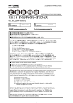
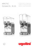
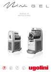
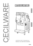
ENGLISH
ARCTIC DELUXE SERIES
ESPAÑOL
ENGLISH
20/1PD - 20/2PD - 20/3PD - 20/4PD
OPERATOR’S MANUAL
MANUAL DE INSTRUCCIONES
NS05A
ARCTIC DELUXE SERIES
1 TECHNICAL CHARACTERISTICS
damage is found, call the delivering carrier immediately to file a
claim.
3 Install the unit on a counter top that will support the combined weight of dispenser and product bearing in mind what is
stated in the preceding point 1 IMPORTANT warning.
4 A minimum of 15 cm (6”) of free air space all around the unit
should be allowed to guarantee adequate ventilation.
5 Ensure that the legs are screwed tightly into the base of the
machine.
Replace the standard legs originally installed with the 100 mm
(4”) legs whenever they are provided with the unit.
6 Before plugging the unit in, check if the voltage is the same
as that indicated on the data plate. Plug the unit into a grounded, protected single phase electrical supply according to the
applicable electrical codes and the specifications of your
machine. Should you prefer to connect the unit directly to the
mains, connect the supply cord to a 2-pole wall breaker, whose
contact opening is at least 3mm (0.125”). Do not use extension
cords.
20/1PD 20/2PD 20/3PD 20/4PD
Transparent removable bowls
1
2
3
4
Gal
Gal
5.4
3.17
5.4
3.17
5.4
3.17
5.4
3.17
width
inches
7.125
14.5
21.25
28.5
depth
inches
18.5
18.5
18.5
18.5
5.4Gal
3.17Gal
inches
26.5
24
26.5
24
26.5
24
26.5
24
Net weight, approx.
5.4Gal
3.17Gal
Lbs
48.5
44
70.5
60
92.5 121.25
79.5
97
Gross weight, approx.
5.4Gal
3.17Gal
Lbs
55
48.5
80
61.75
102
88.25
130
108
1
2
3
4
Capacity
approx.
of
each
n
bowl, Standard
Optional
Dimensions:
height
Adjustable thermostats
n
Hermetic compressor
Air-cooled condenser
Overload protector
Noise level lower than 70 dB (A)
ATTENTION
Failure to provide proper electrical ground according to
applicable electrical codes could result in serious shock
hazard.
IMPORTANT
Read electrical ratings written on the data plate of the
individual units; the data plate is adhered on the dispensing side panel of the unit, just behind the drip tray (the
right side drip tray in multiple bowl models). The serial
number of the unit (preceded by the symbol #) is adhered
just below the right bowl. Data plate specifications will
always supersede the information in this manual.
7 The unit doesn’t come presanitized from the factory. Before
serving products, the dispenser must be disassembled, cleaned and sanitized according to this handbook instructions
(chapter 5.3 CLEANING AND SANITAZING PROCEDURES).
Specifications are subject to change without notice.
IMPORTANT
2 INTRODUCTION
Install the dispenser so that the plug is easily accessible.
Please read all sections of this manual thoroughly to familiarize
yourself with all aspects of the unit.
Like all mechanical products, this machine will require cleaning
and maintenance. Besides, dispenser working can be
compromised by operator’s mistakes during disassembly and
cleaning. It is strongly recommended that personnel responsible
for the equipment’s daily operations, disassembly, cleaning,
sanitizing and assembly, go through these procedures in order
to be properly trained and to make sure that no
misunderstandings exist.
4 TO OPERATE SAFELY
1 Do not operate the dispenser without reading this operator’s manual.
2 Do not operate the dispenser unless it is properly grounded.
3 Do not use extension cords to connect the dispenser.
4 Do not operate the dispenser unless all panels are restrained with screws.
5 Do not obstruct air intake and discharge openings: 15 cm
(6”) minimum air space all around the dispenser.
6 Do not put objects or fingers in panels louvers and faucet
outlet.
7 Do not remove bowls, augers and panels for cleaning or
routine maintenance unless the dispenser is disconnected from
its power source.
3 INSTALLATION
1 Remove the corrugate container and packing materials and
keep them for possible future use.
IMPORTANT
ATTENTION
When handling the machine never grasp it by the bowls
or by the evaporator cylinders. The manufacturer refuses
all responsibilities for possible damages which may
occur through incorrect handling.
In case of damages, the power cord must be replaced by
qualified personnel only in order to prevent any shock
hazard.
8 This unit is not meant to be used outside.
2 Inspect the uncrated unit for any possible damage. If
2
5. 2 OPERATION HELPFUL HINTS
9 This unit is not to be installed in areas subject to waterspouts..
10 Do not use water-jets to clean the unit.
11 This unit can work in a room temperature range between
+5° and +32°C (41F and 90F).
1 The length of time for cooling down the product is governed
by many variables, such as ambient temperature and beverage
initial temperature.
2 To shorten product cooling down time and increase productivity, it is advisable to pre-chill the product to be used in the
dispenser.
3 To shorten product cooling down time and increase productivity, the bowl should be refilled after the product level drops
lower than half and at the start of each day.
4 The dispenser must be able to emit heat.
In case it seems excessive, check that no heating source is
close to the unit and air flow through the slotted panels is not
obstructed by wall or boxes. Allow at least 15 cm (6”) of free
clearance all around the dispenser.
In any case if the product in the bowls is cold the unit is running
properly.
5 How to reset beverage temperature:to reset beverage temperature please apply to a technician.
The proper temperature is preset at the factory.
5 OPERATING PROCEDURES
1 Clean and sanitize the unit according to the instructions in
this manual. See chapter 5.3 CLEANING AND SANITIZING
PROCEDURES.
2 Fill the bowls with product to the maximum level mark. Do
not overfill.
The exact quantity of product (expressed as liters and gallons)
is shown by marks on the bowl.
3 In case of products to be diluted with water, potable water,
pour water into bowl first, then add correct quantity of product.
In case of natural squashes, it is advisable to strain them, in
order to prevent pulps from obstructing the faucet outlet.
4 Install the covers and check that they are correctly placed
over the bowls.
5 Set the control switches as shown in chapter
5.1 DESCRIPTION OF CONTROLS.
6 The dispenser must always run with the covers installed to
prevent a possible contamination of the product.
7 Always leave the dispenser on, as the refrigeration stops
automatically when the beverage reaches the dispensing temperature. The mixing devices will continue to turn.
8 To maintain a high standard of flavour, keep refrigeration
and mixing devices on during the night when beverage is in the
bowl.
5. 3 CLEANING AND SANITIZING
PROCEDURES
Cleaning and sanitizing of the dispenser are recommended to
guarantee the conservation of the best product taste and the
highest unit efficiency. This section is a procedural guideline
only and is subject to the requirements of the local Health
Authorities.
Prior to the disassembly and cleaning, the machine must be
emptied of product.
5. 3. 1 DISASSEMBLY
IMPORTANT
Operate the dispenser with food products only.
5. 1 DESCRIPTION OF CONTROLS
ATTENTION
Before any disassembly and/or cleaning procedure make
sure that the dispenser is disconnected from its power
source by unplugging it or switching off the 2-pole wall
breaker.
The dispenser is equipped with a power switch and each bowl is
operated by a mixing device switch.
Their functions are as follows:
Power switch
0 position
: Power is turned OFF to all
functions.
I position
This position operates the fan
motor and makes the mixing
: devices suitable to be turned
on by relevant switches.
1 Remove cover from the bowl.
2 Remove the empty bowl by lifting first its front side (faucet
side) up and off bowl gasket (see figure 1).
Mixing device switch
0 position
: OFF.
I position
: Mixing device runs.
figure 1
To operate the dispenser
3 Remove the bowl gasket.
4 Remove the pump impeller from its location.
5 Gravity faucet: extract the piston and then remove the
1 Set power switch to I position.
2 Set mixing device switch(es) to I position.
3
ARCTIC DELUXE SERIES
4 In the same manner clean the evaporator cylinder(s) using
a soft bristle brush.
5 Rinse all cleaned parts with cool clean water.
dispensing handle (see figure 2).
5. 3. 3 SANITIZING
Sanitizing should be performed immediately prior to
starting the machine. Do not allow the unit to sit for
extended periods of time after sanitization.
1 Wash hands with a suitable antibacterial soap.
2 Prepare at least two gallons of a warm (45-60 °C 120140 °F) sanitizing solution (100 PPM available chlorine concentration or 1 spoon of sodium hypoclorite diluted with two litres,
0.5 gallons of water) according to your local Health Codes and
manufacturer’s specifications.
3 Place the parts in the sanitizing solution for five minutes.
4 Do not immerse the lighted top covers in liquid. Carefully
wash their undersides with the sanitizing solution.
5 Place the sanitized parts on a clean dry surface to air dry.
6 Wipe clean all exterior surfaces of the unit. Do not use abrasive cleaner.
figure 2
6 Slide drip tray out and empty it.
5. 3. 2 CLEANING
5. 3. 4 ASSEMBLY
1 Slide the drip tray into place.
2 Gravity faucet: install the faucet handle and the piston with
its gasket (see figure 3).
IMPORTANT
Do not attempt to wash any machine components in a
dishwasher.
ATTENTION
Before any disassembly and/or cleaning procedure make
sure that the dispenser is disconnected from its power
source.
1 Prepare at least two gallons of a mild cleaning solution of
warm (45-60 °C 120-140 °F) potable water and dishwashing
detergent. Do not use abrasive detergent.
Important: if present, follow label directions, as too strong a
solution can cause parts damage, while too mild a solution will
not provide adequate cleaning.
figure 3
3 Fit the bowl gasket to the evaporator. Note: the largest brim
of the gasket must face against the drip plate (see figure 4).
IMPORTANT
In order to prevent any damage to the dispenser use only
a detergent suitable with plastic parts.
2 Using a brush, suitable for the purpose, thoroughly clean all
disassembled parts in the cleaning solution.
ATTENTION
When cleaning the machine, do not allow excessive
amounts of water around the electrically operated components of the unit. Electrical shock or damage to the
machine may result.
figure 4
4 Place bowl on the unit. Wet the gasket for ease of insertion.
Please take care that the hook on the backside of the bowl be
inserted properly in its seat on the upper drip plate. (see figure
3 Do not immerse the lighted top covers in liquid. Wash them
apart with the cleaning solution. Carefully clean their undersides.
4
5).
figure 5
5 Use fresh product to chase any remaining sanitizer from the
bowl(s). Drain this solution. Do not rinse out the machine.
5. 4 IN-PLACE SANITIZATION
Daily: The In-Place Sanitization prior to starting the machine
may be performed, if needed, only as further precaution, in
addition to the Disassembled Parts Sanitization described
before, but never in lieu of it.
1 Prepare two gallons of a warm (45-60°C, 120-140 °F) sanitizing solution (100 PPM available chlorine concentration or 1
spoon of sodium hypoclorite diluted with two litres, 0.5 gallons
of water) according to your local Health Codes and manufacturer’s specifications.
2 Pour the solution into the bowl(s).
3 Using a brush suitable for the purpose, wipe the solution on
all surfaces protruding above the solution-level and on the
underside of the top cover(s).
4 Install the top cover(s) and operate the unit. Allow the solution to agitate for about two minutes. Drain the solution out of
the bowl(s).
5 Use fresh product to chase any remaining sanitizer from the
bowl(s). Drain this solution. Do not rinse out the machine.
6 ROUTINE MAINTENANCE
Daily: inspect the machine for signs of product leaks past seals
and gaskets. If proper assembly does not stop leaks around
seals or gaskets, check for improper lubrication, worn or
damaged parts. Replace parts as needed with original spare
parts from the supplier.
6. 1 MAINTENANCE (TO BE CARRIED OUT BY
QUALIFIED SERVICE PERSONNEL ONLY)
Monthly: clean all internal components, primarily the
condenser, using compressed air.
To clean these internal parts, unplug the unit or switch off the 2pole wall breaker, then remove front panel (dispensing side).
Condenser fins are very sharp. Use extreme caution when cleaning.
5
ARCTIC DELUXE SERIES
2 Controlar que el distribuidor no haya sufrido daños durante
el transporte. De haberlos sufrido, reclamar inmediatamente al
transportista.
3 Colocar el distribuidor en un mostrador en grado de
sostener su peso incluso con la carga completa, teniendo en
cuenta cuanto indicado en IMPORTANTE, del punto 1.
4 Dejar un espacio libre de por lo menos 15 cm (6”) alrededor
del aparato para no impedir el flujo de aire de refrigeración.
5 Controlar la estabilidad del aparato, regulando la altura de
los pies.
6 Grifo en acero inox por gravedad. Montar el grifo, teniendo
en cuenta cuanto indicado en 5.3.4. REMONTAJE.
7 Antes de enchufar el aparato con la toma de corriente
controlar que la tensión de la red sea aquella indicada en la
placa. Enchufar el distribuidor a una red monofásica,
sirviéndose de una toma completa de tierra, según lo previsto
por la normativa vigente. En el supuesto de realizar una
conexión fija a la red, conectar el cable a un interruptor de
pared de tipo bipolar con apertura de contactos de 3 mm
(0.125”) por lo menos. No utilizar cordones conectores para
enchufar el aparato al suministro de corriente eléctrica.
1 CARACTERISTICAS TECNICAS
20/1PD 20/2PD 20/3PD 20/4PD
Contenedores transparentes
desmontables
1
2
3
4
Gal
Gal
5.4
3.17
5.4
3.17
5.4
3.17
5.4
3.17
ancho
inches
7.125
14.5
21.25
28.5
largo
inches
18.5
18.5
18.5
18.5
5.4Gal
3.17Gal
inches
26.5
24
26.5
24
26.5
24
26.5
24
Peso neto, aproximado
5.4Gal
3.17Gal
Lbs
48.5
44
70.5
60
92.5 121.25
79.5
97
Peso bruto, aproximado
5.4Gal
3.17Gal
Lbs
55
48.5
80
61.75
102
88.25
130
108
1
2
3
4
Capacidad de cada
contenedor, aproximada
n
Standard
Optional
Dimensiones:
alto
Termostatos regulables
n
Motocompresor hermético
Condensador a ventilación forzada
Guardamotor
Nivel de ruido inferior a 70dB (A)
ATTENCION
IMPORTANTE
Cerciorarse que el aparato esté correctamente
conectado a tierra; en caso contrario es posible causar
shock eléctricos a las personas o dañar el distribuidor.
Características eléctricas: leer los datos detallados en la
placa del distribuidor; ésta se encuentra en la parte inferior del panel frontal, detrás del cajón recoge-gotas de la
derecha. Los números de matrícula de los aparatos (precedidos por el símbolo#) están colocados dentro del
alojamiento portatinterruptores de izquierda. Los datos
detallados sobre la placa son aquellos a los que se debe
siempre hacer referencia.
8 El distribuidor no sale de fábrica prelavado e higienizado.
Antes de utilizarlo debe ser desarmado, lavado e higienizado
siguiendo cuanto dicho en las presentes instrucciones del
capítulo 5.3 LIMPIEZA.
Se reserva el derecho de efectuar modificaciones sin previo
aviso.
4 PARA UN FUNCIONAMIENTO SEGURO
2 INTRODUCCION
1 No utilizar el distribuidor antes de haber leído el presente
manual de instrucciones.
2 No utilizar el distribuidor si no está correctamente
conectado a tierra.
3 No utilizar cordones conectores para enchufar el
distribuidor al suministro de corriente.
4 No poner en funcionamiento el distribuidor si los paneles no
se encuentran en su lugar y fijados con los tornillos.
5 No impedir el flujo de aire de refrigeración, dejar un espacio
libre de por lo menos 15 cm alrededor del distribuidor.
6 No introducir los dedos u objetos en las ranuras de los
paneles y en la apertura del grifo.
7 No desmontar el contenedor, no quitar los mezcladores o
paneles para limpieza o manutención sin cerciorarse que el
distribuidor esté desenchufado del suministro de corriente.
Les aconsejamos que lean atentamente este manual de
instrucciones para conocer todas las características del
distribuidor.
También este distribuidor, como todos los productos
mecánicos, necesita de limpieza y cuidado. Se corre el riesgo
de impedir su buen funcionamiento si se verificasen errores
cometidos por el usuario durante la fase de desmontaje y
limpieza. Por dicho motivo es importante que los
procedimientos de desmontaje, lavado, higienización y
limpieza, siendo operaciones cotidianas, sean conocidas sin
posibilidad de error por todo el personal responsable del
distribuidor.
3 INSTALACION
1 Quitar el distribuidor del embalaje: guardar este último por
si hubiera cualquier eventualidad.
ATTENCION
Si el cable de alimentación está dañado, debe ser substituito por el fabricante o desde su servicio de asistencia
técnica o, en cualquier caso, por una persona cualificada con el fin de evitar cualquier tipo de riesgo.
IMPORTANTE
En la operación de transporte o levantamiento no se
debe coger nunca el distribuidor por sus contenedores
transparentes o por los cilindros evaporadores.
El fabricante no responde de los daños acarreados por
estas maniobras equivocadas.
8 Aparato no apto para uso exterior.
9 Aparato no apto en instalaciones donde haya cercano
fuentes de agua .
10 Para la limpieza no utilizar chorros de agua.
6
11 Para el correcto funcionamiento, coma la temperatura
ambiente debe estar comprendida ientre 5°C y 32°C (14F y
90F).
Para el funcionamiento del distribuidor:
1 Colocar el interruptor general en posición I.
2 Colocar el interruptor agitación en posición I.
5 INSTRUCCIONES DE EMPLEO
5. 2 SUGERENCIAS
1 Lavar e higienizar el distribuidor antes de utilizarlo
siguiendo cuanto se ha dicho en las presentes instrucciones en
el capítulo 5.3 LIMPIEZA.
2 Llenar los contenedores con el producto deseado hasta
que alcance el nivel máximo indicado (no superar dicho nivel).
La cantidad de producto presente en el contenedor (en litros o
en galones) está indicada con señales específicas situadas en
el contenedor mismo.
3 Si se quiere distribuir productos concentrados a diluirse con
agua, verter en los contenedores el agua agregando a
continuación la cantidad necesaria de producto concentrado,
según las instrucciones del fabricante. Si se quieren emplear
zumos naturales se recomienda filtrarlos para evitar que las
partes sólidas puedan obstruir el pasaje del grifo.
4 Montar las tapas sobre los contenedores cerciorándose
que queden bien colocadas.
5 Accionar los interruptores (ver capítulo 5.1 DESCRIPCIÓN
DE LOS MANDOS).
6 El distribuidor debe funcionar siempre con las tapas
montadas para prevenir una posible contaminación del
producto.
7 El distribuidor debe funcionar ininterrumpidamente: el
grupo frigorífico se parará automáticamente cuando el
producto esté listo para ser distribuido. Los dispositivos
mezcladores seguirán funcionando.
8 Para la buena conservación del producto, el distribuidor
deberá funcionar también durante la noche.
1 El tiempo necesario para obtener la refrigeración del
producto varía en función de distintos factores como por
ejemplo la temperatura ambiente y la temperatura inicial del
producto.
2 Llenando los contenedores con producto ya enfriado
previamente se incrementa la eficiencia del distribuidor.
3 Para
disminuir
ulteriormente
los
tiempos
de
restablecimiento y, por lo tanto, aumentar la autonomía del
distribuidor, volver a llenar cuando el nivel del producto
desciende a mitad evaporador.
4 Todos los distribuidores de este tipo deben despedir calor.
Si el calor producido fuera excesivo, controlar que ninguna
fuente de calor se encuentre cerca del distribuidor y, en modo
particular, cerca de las rejillas de los paneles. Cerciorarse
además, que el flujo de aire no esté obstaculizado por paredes
cercanas, cajas u otras cosas. Dejar por lo menos 15 cm (6”)
de espacio libre alrededor del distribuidor. En todo caso
cuando el producto dentro de los contenedores está frio, es
señal de que todo funciona bien y que el calor producido no es
alarmante.
5 Regulación de la temperatura: para este tipo de operación,
dirigerse exclusivamente al técnico.La temperatura ideal de las
bebidas ha sido establecida y regulada en la fábrica.
5. 3
La limpieza y el lavado son fundamentales para garantizar la
perfecta conservación del gusto de la bebida y la máxima
eficiencia de vuestro distribuidor. Los procedimientos descritos
a continuación deben ser considerados de carácter general y
pueden variar por efecto de la reglamentación de higiene
vigente.
Antes del desarmado para el lavado del distribuidor debe
quitarse todo el producto.
IMPORTANTE
Utilizar el distribuidor solamente con productos alimenticios.
5. 1
LIMPIEZA
DESCRIPCION DE LOS MANDOS
5. 3. 1
El distribuidor está provisto de un interruptor general y, para
cada contenedor, de un interruptor para el mando del
dispositivo de agitación.
A continuación describimos la variedad de las funciones de los
interruptores:
DESMONTAJE
ATTENCION
Interruptor general
Posición 0
: el distribuidor está apagado.
Posición I
el distribuidor está habilitado
: para el funcionamiento.
Ventilador en función.
Antes de proceder con el desmontaje de cualquier componente, desenchufar de la toma de corriente eléctrica el
enchufe del aparato o bien apagar el interruptor externo
de pared.
1 Quitar la tapa del contenedor.
2 Quitar el contenedor vacío levantándolo por la parte
anterior y desprendiendolo de la junta (ver figura 1).
Interruptor agitación
Posición 0
: dispositivo de agitación parado.
Posición I
: dispositivo de agitación en
función.
figura 1
7
ARCTIC DELUXE SERIES
3 Quitar la junta del contenedor.
bebida.
4 Sacar la turbina pompa.
ATTENCION
5 Grifo en acero inox por gravedad: Sacar el pisón y
desmontar la palanca mando grifo (ver figura 2).
Durante el lavado del distribuidor no usar mucha cantidad de agua cerca de los componentes eléctricos; en
caso contrario es posible que se verifiquen shock eléctricos o también se dañe el distribuidor.
3 Enjuagar todas las partes con agua corriente
5. 3. 3
REMONTAJE
1 Colocar el cajón recoge-gotas en su alojamiento.
2 Grifo en acero inox por gravedad: montar la palanca
figura 2
mando grifo y enfilar el pisón unido a la su junta (ver figura 3).
6 Sacar el cajón recoge-gotas y vaciarlo.
5. 3. 2
LAVADO
IMPORTANTE
No lavar ningún componente de la maquina en lavavajillas.
figura 3
ATTENCION
3 Poner la junta al evaporador, de modo que el borde de
Antes de efectuar cualquier tipo de limpieza, desenchufar de la toma de corriente eléctrica el enchufe del aparato o bien apagar el interruptor externo de pared.
mayor ancho se quede en contacto con el plano recoge-gotas
(ver figura 4).
1 Poner en una palangana aproximadamente ocho litros de
agua caliente (45°-60°C) (120F-140F) y detergente apropiado
respetando con atención las instrucciones del fabricante; una
solución demasiado concentrada de detergente puede
provocar daños en las partes a lavar, en vez una solución
demasiado diluida puede no limpiar bastante. No utilizar
detergentes abrasivos.
figura 4
IMPORTANTE
Para prevenir daños al distribuidor utilizar solamente un
detergente compatible com las partes de plastico.
4 Poner el contenedor sobre el distribuidor. Por facilitar esta
operación, mojar la junta con un poco de agua.
2 Emplear un cepillo apropiado y lavar minuciosamente con
la solución detergente todas las partes en contacto con la
Asegurarse que el gancio posterior del contenedor estè
insertado en el lugar correcto del piano recoge-gotas.
8
(ver figura 5)
de pared, a continuación desmontar el panel.
Prestar atención a las aletas del condensador porque tienen filo.
figura 5
5 Enjuagar con bebida fresca para eliminar todo residuo
posible de solución para higienizar del fondo de los
contenedores. Secar la parte interior de los contenedores con
una servilleta de papel desechable.
5. 4
HIGIENIZACION DEL DISTRIBUIDOR
MONTADO
Cada día: La higienización del aparato montado, antes de ser
puesto en funcionamiento, puede ser efectuada, si es
necesario, solamente como una ulterior prevención adicional a
la higienización del aparato desmontado descrito
anteriormente, pero no debe sustituir jamás a la efectuada con
el aparato desmontado.
1 Poner en una palangana una solución de agua o producto
para higienizar aprobado por las autoridades de vuestro país,
respetando las especificaciones del fabricante. Si se carece de
un producto para higienizar específico, preparar una solución
de agua e hipoclorito de sodio (lejía uso alimenticio) en la
proporción de 1 cucharadita por cada 2 litros (0.5 gallons) de
agua.
2 Verter la solución en los contenedores.
3 Usando un cepillo apropiado fregar con la solución todas
las partes sobre el nivel de la solución y sobre la parte inferior
de la tapa.
4 Colocar la tapa y poner en función el distribuidor de modo
que permita a la solución agitarse 2 minutos.
5 Vaciar los contenedores de la solución para higienizar por
medio de los grifos.
6 Enjuagar con bebida fresca para eliminar del fondo de los
contenedores todo residuo posible de solución para higienizar.
Secar la parte interior de los contenedores con una servilleta
de papel desechable.
7 No efectuar más operaciones de enjuague.
6 MANUTENCION
Cada día: controlar el distribuidor y que no se verifiquen
pérdidas de producto de las juntas. Si se notasen pérdidas,
controlar , antes de todo, que el distribuidor esté montado
correctamente, luego que las juntas no necesiten lubricación y,
por último, que dichas juntas no sean defectuosas o estén
gastadas, si es así reemplazarlas con recambios originales del
fabricante.
6. 1
MANUTENCION (SOLAMENTE POR EL
SERVICIO POSTVENTA)
Cada mes: eliminar el polvo que se acumula sobre el filtro del
condensador. Antes de efectuar dicha operación desenchufar el
distribuidor de la toma de corriente o bien apagar el interruptor
9
ARCTIC DELUXE SERIES
SPARE PARTS LIST
DESCRIPCION PIEZAS DE REPUESTO
46
47
48
49
50
10
2408_49 V 0.4 08A09
1
2
6
7
8
9
10
11
12
13
14
15
16
17
17
19
20
21
26
27
30
31
32
33
34
35
36
37
37A
38
38A
38B
39
40
41
42
43
44
45
46
47
48
49
50
00651
00651
00653
00655
00656
00112
00117
00116
00045
RRR
00652
00725
00657
00671
00654
00672
00077
00028
00659
00660
00006
00048
00237
00297
00265
>>>
>>>
00313
00133
00045
00673
00298
00179
00158
RRR
00532
00564
00565
00004
00674
00675
33900-01011
00676
00678
00679
5.4gal It bowl cover
3.17gal bowl cover
Bowl gasket
Plastic I-beam for connection
Central pivot
Central pivot OR
Motor magnet
Motor bracket
Motor
Back panel
5.4gal bowl for pump
Spray tube for 3.17gal bowl
12 l bowl for pump
Fast agitation impeller (Blue)
Gentle agitation impeller (Grey)
Bent tube for 5.4gal bowl
Faucet piston
Faucet gasket
Picture
Push handle
Switch
Switch cap
Side panel
Terminal block cover
Terminal block with cable clamp
Overload protector
Relay
Fan for 3.17gal
Fan for 5.4gal
Fan motor for 3.17gal
Fan motor for 5.4gal
Fan motor for 1 bowl
Clip
Rubber leg
Dispensing side panel
Stainless steel fixing screw for panel
Drip tray cover
Drip tray
Thermostat
Central pivot
Washer
Impeller mixer motor
Mixer motor
Pump motor bracket
Tapa contenedor 5.4gal
Tapa contenedor 3.17gal
Junta contenedor
Perfil de union
Pivote central
OR del pivote central
Embrague magnetico
Placa soporte motor
Motor
Panel postsrior
Contenedor 5.4gal para bomba
Tubo de flujo para contenedor 3.17gal
Contenedor 12 l para bomba
Turbina bomba 60Hz
Turbina bomba
Tubo de flujo para contenedor 5.4gal
Pistón del grifo
Junta del grifo
Fotografia
Palanca de mando grifo
Interruptor
Protección interruptor
Panel lateral
Protección pasacable
Pasacable
Guardamotor
Relé
Aspas para 3.17gal
Aspas para 5.4gal
Motor ventilador por 3.17gal
Motor ventilador por 5.4gal
Motor ventilador por 1 behalter
Clip
Pie nivelador
Panel lado grifo
Tornillo inox fijacion paneles
Rejilla cajón
Cajón recoge-gotas
Termostato
Pivote central
Arandela
Turbina motor agitador
Motor agitador
Placa soporte motor bomba
>>>
RRR
Please order what printed on piece
See table
Pedir com la identificación marcada en la pieza
Ver tabla
RRR
13
41
20/1PD
00306
00239
20/2PD
00717
00240
20/3PD
00723
00241
20/4PD
00724
00722
11
ARCTIC DELUXE SERIES
WIRING DIAGRAM
SCHEMA ELECTRIQUE
ESQUEMA ELECTRICO
1
2-3-4-5
6-7-8-9
10-11-12-13
14
15
Switch
Thermostat
Pump/mixer switch
Pump/mixer
Fan Motor
Compressor
Interrupteur
Thermostat
Interrupteur pompe/brasseur
Pompe/brasseur
Moteur ventilateur
Compresseur
12
Interruptor
Termostato
Interruptor bomba/agitador
Bomba/agitador
Ventilador
Motocompresor
NOTES- NOTAS:
13
ARCTIC DELUXE SERIES
NOTES- NOTAS:
14
NOTES- NOTAS:
15
CECILWARE CORPORATION
43-05 20th Avenue
Long Island City, N.Y. 11105
Tel. (800) 935 2211
Fax (718) 932 7860
Email : [email protected]
www.cecilware.com
2408_49 V0.4 08A09