1
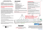
2. PRESENTATION Voltage Stabilizer Owner’s Manual Voltage Stabilizer unit can provide you with microprocessor controlled Automatic Voltage Regulation function. It will supply your equipment with pure and stable power. 2.1 OFF mode: – no indicator The situation caused by 1. Power switch is turn-off 2. Manual switch is tripped 3. No utility power Thank you for purchasing the Voltage Stabilizer made by OPTI-UPS. This owner’s manual includes important safety guidelines for 2.2 NORMAL mode: –indicator (green) operation and the installation procedures of this Voltage Stabilizer. If The indicator will illuminate when the utility input is normal. you have any problems with this product, please refer to this manual, before contacting customer service. 2.3 BUCK mode: – indicator (yellow) The indicator will illuminate when the voltage of utility input is high. Utility input is over the rated limit; the buck mode of 1. IMPORTANT SAFETY INSTRUCTIONS automatic voltage regulator is enabled. WARNING: (SAVE THESE INSTRUCTIONS): This manual 2.4 BOOST mode:– indicator (yellow) contains important instructions that must be followed during The indicator will illuminate when the voltage of utility input is low. installation and maintenance of this Voltage Stabilizer. Utility input is under the rated limit; the buck mode of automatic voltage regulator is enabled. WARNING: (Controlled Environment): Intend for installation in a controlled environment. CAUTION: Risk of electric shock, do not remove cover. No user serviceable parts inside. Refer servicing to qualified service personnel. CAUTION: Avoid exposing Voltage Stabilizer to direct sunlight, stoves or any other heat source. CAUTION: Prevent overheating by making sure that the ventilation openings of the unit are not covered. CAUTION: Keep unit away from any moisture or dusty areas. 3. INSTALLATION 3.1 Inspection: Inspect the Voltage Stabilizer upon receipt. The packaging is recyclable; save it for reuse or dispose of it properly. 3.2 Placement: Install Voltage Stabilizer in controlled area with adequate air flowing and free of excessive dust. Do not operate the Voltage Stabilizer in an outdoor environment. 3.3 Utility Power: Be sure the polarities and types of the receptacles match the unit. The capacity of this unit must be higher than the protected load. If the capacity of Voltage Stabilizer unit is not sufficient, the manual switch will pop out. 4. OPERATION 4.1 Switch on: When the Voltage Stabilizer is connected to utility input, press the “ON” button to turn on the Voltage Stabilizer. Then connect the electrical cords of the equipments that will be used (such as computer or monitor) to the rear panel of the Voltage Stabilizer unit. 4.2 Switch off: Press the “OFF” button to turn off the Voltage Stabilizer. 4.3 Over load protection: In the event of an over load condition, the input manual switch will pop out. This is a safety protection. 4.4 Output short circuit protection: When the output loads are shorted, the input manual switch will pop out. This will protect the AVR. Warning: Once the manual switch is opened, please turn on the unit again after 60 seconds to let the manual switch cool down. This can extend the life of the manual switch. Front Panel LED 5. TROUBLESHOOTING Problem Voltage Stabilizer cannot be turned on Possible Cause ON/OFF switch is in the OFF position Manual return switch is opened Action to Take Press ON/OFF switch to ON position Turn on the manual return switch 6. SPECIFICATIONS MODEL SS1200 SS2000 Capacity 600W 1000W INPUT Voltage 110V, 115V, 120V +/-15% Frequency 50 or 60Hz Voltage 110V, 115V, 120V Typical +/- 5% OUTPUT Frequency 50 or 60Hz Overload Manual return switch Short Circuit Manual return switch Surge Energy PROTECTION 525J Rating Data Line RJ11 Protection Net weight 1.6/ 3.52 1.8/3.96 (kg/lb) PHYSICAL Dimension 123*136*102(mm) (W*L*H) Ambient 3,500 meters max. elevation, 0~95 operation humidity non-condensing, 0~40˚C ENVIRONMENT Audible Noise <40dBA (1 meter from surface) Storage 15,000 meters max. Condition *Specifications are subject to change without notice 2. PRESENTACIÓ N ESTABILIZADOR DE VOLTAJE MANUAL DE INSTRUCCIONES Esta unidad provee la función de estabilizar el voltaje mediante un microprocesador de control, con el objetivo de ofrecerle una energía pura y estable. 1.1 Modo “OFF” (Indicadores Apagados) Representa: 1. Unidad apagada. 2. Interruptor Térmico averiado. 3. Sin corriente eléctrica. ¡Por favor estudie cuidadosamente y conserve este manual! Muchas gracias por elegir nuestro Estabilizador de Voltaje. La 1.2 Modo “Normal” (Indicador Color Verde) Representa un funcionamiento normal. unidad le proveerá una protección perfecta de los aparatos conectados. Este manual es una guía de instalación y empleo que incluye importantes instrucciones de seguridad para la 1.3 Modo “Buck-down”(Indicador Color Amarillo) El indicador se enciende cuando se produce una subida de tensión. operación y la instalación correcta del Estabilizador de Voltaje. Cuando la tensión sobrepasa el límite, el modo de regulación de Si se encuentra con algún problema al utilizarlo, favor refiérase voltaje “buck’down” se activa automáticamente. al manual antes de llamar al servicio de atención al cliente. 1. IMPORTANTES INSTRUCCIONES DE SEGURIDAD AVISO (Conserve estas instrucciones) Este manual contiene importantes instrucciones que deberán ser seguidas durante la instalación y mantenimiento del Estabilizador de Voltaje. AVISO (Ambiente Controlado): Asegúrese de instalar el dispositivo bajo un ambiente controlado. PRECAUCIÓ N: La unidad no contiene piezas reusables. No abra la caja superior para prevenir cortocircuitos. Atienda a personal de servicio capacitado. PRECAUCIÓ N: Evite que el Estabilizador de voltaje sea expuesto al sol, calentadores, u otras fuentes de calor. PRECAUCIÓ N: Para prevenir el sobrecalentamiento, asegúrese de que las aperturas de ventilación no estén cubiertas. PRECAUCIÓ N: Mantega la unidad fuera del polvo y la humedad. 3. INSTALACIÓ N 3.1 Inspecciones: Inspeccione el Estabilizador al recibirlo. El empaquetado es reciclable, consérvelo o recíclelo apropiadamente. 3.2 Localización: Instale el Estabilizador de Voltaje en áreas controladas con buena ventilación y libre de polvo. No operar el Estabilizador al aire libre. 1.4 Modo “Boost” (Indicador Color Amarillo) El indicador se enciende cuando se produce una bajada de tensión. Cuando la tensión es inferior al imite, el modo de regulación de voltaje “buck” se activa automáticamente. Panel Frontal LED 5. LOCALIZACIÓ N DE AVERÍAS Problema No se enciende el Estabilizador Causas Posibles El botón de ON-/OFF esta fuera de posición Interruptor Térmico fuera de servicio 3.3 Alimentación: 6. ESPECIFICACIONES Asegúrese de que las polaridades y tipos de receptores coincidan con la unidad. Por otra parte, asegúrese de que las cargas de los aparatos MODELO conectados se mantengan menor a la capacidad de la unidad. 4. OPERACIÓ N 4.1 Botón “ON”: Bajo alimentación, presione “ON” para encender el Estabilizador de Voltaje. Luego conecte los aparatos a conectar (ej: monitor de ordenador) a los tomacorrientes en el panel trasero del Estabilizador de Voltaje. 4.2 Botón “OFF”: Para apagar el Estabilizador de Voltaje, presione el botón “OFF”. 4.3 “Protección de Sobrecarga”: Cuando la unidad este funcionando bajo sobrecarga, el Interruptor Térmico queda fuera de servicio para protejer la unidad. 4.4 “Protección de cortocircuito”: Cuando la unidad este funcionando bajo cortocircuito en las cargas, el Interruptor Térmico queda fuera de servicio para proteger la unidad. Calentamiento: Una vez fuera de servicio, espere 60 segundos antes de encender la unidad para que el Interruptor Térmico vuelva a la normalidad. Este proceso ayuda a prolongar la vida del Interruptor. Acciones Aplicables Presione el botón de encendido Reencienda el Interruptor Térmico SS1200 SS2000 Capacidad 600W 1000W ENTRADA Voltaje 110V, 115V, 120V +/-15% Frequencia 50 o 60Hz Voltaje 110V, 115V, 120V Tipico +/-5% SALIDA Frequencia 50 o 60Hz Sobrecargas Protección Interruptor Térmico Cortocircuito Protección Interruptor Térmico PROTECCIÓ N Onda de Energia 525J Protección para RJ11 Liña de datos Peso Neto (kg/lb) 1.6/ 3.52 1.8/3.96 CARACTERÍST Dimensiones ICAS FÍSICAS Ancho*Fondo*Al 123*136*102(mm) to Ambiente de 3,500 m máxima alture, 0~95 Operación Humedad, 0~40˚C AMBIENTE Ruidos audibles <40dBA (1 metro de la superficie Condiciones de 15,000 metros máx. Almacenamiento *Subjecto de especificaciones estará combiada por las noticias