1
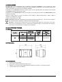
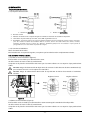
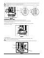
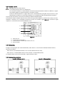
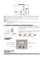
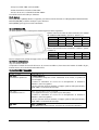
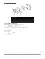
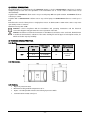
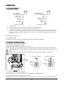
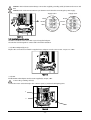
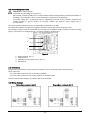
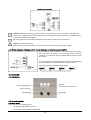
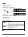
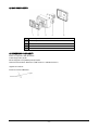
ELV
(ES) MANUAL DE INSTRUCCIONES .......... 2
(EN) INSTRUCTIONS MANUAL ...............10
-1-
ES
Advertencia para la seguridad.
La siguiente simbología
junto a un párrafo indica la posibilidad de peligro como consecuencia de
no respetar las prescripciones correspondientes.
PELIGRO
La no advertencia de esta prescripción comporta un riesgo de electrocución.
Riesgo
de
electrocución
PELIGRO
La no advertencia de esta prescripción comprota un riesgo de daño a personas o
cosas.
ATENCIÓN
La no advertencia de esta prescripción comporta un riesgo de daños a la bomba o
a la instalación.
ÍNDICE
1) GENERALIDADES........................................................................................................................................... 3
2) CARACTERÍSTICAS TÉCNICAS. ........................................................................................................................ 3
2.1) Modelos. ............................................................................................................................................... 3
2.2) Dimensiones. ........................................................................................................................................ 3
2.3) Características....................................................................................................................................... 3
3) INSTALACIÓN. .............................................................................................................................................. 4
3.1) Instalación hidráulica. ........................................................................................................................... 4
3.2) Conexión eléctrica a motor. .................................................................................................................... 4
3.3) Instalación sobre la bomba. ................................................................................................................... 5
3.4) Conexión a la red. .................................................................................................................................. 6
3.5) Protecciones.......................................................................................................................................... 6
3.6) Esquemas de conexiones. ...................................................................................................................... 6
3.7) Esquemas de conexiones de señales y para control mediante presostatos externos ................................. 7
4) FUNCIONAMIENTO. ....................................................................................................................................... 7
4.1) Indicaciones. ......................................................................................................................................... 7
4.2) Modos de funcionamiento...................................................................................................................... 7
5) CONFIGURACIÓN. ......................................................................................................................................... 8
6) PUESTA EN MARCHA. .................................................................................................................................... 8
7) PROTECCIÓN Y ERRORES. .............................................................................................................................. 8
8) COMPONENTES PRINCIPALES ........................................................................................................................ 9
9) DECLARACIÓN DE CONFORMIDAD .................................................................................................................. 9
-2-
1) GENERALIDADES.
El módulo ELV es un complemento para el variador de frecuencia SPEEDRIVE o para el cuadro de control
CONTROLDRIVE, para la constitución de grupos de presión múltiples. El Speedrive o el Controldrive actúan como
cuadro principal de control del grupo (en adelante: Master)
Juntamente con un SPEEDRIVE permite el arranque y paro de una segunda bomba. Sin regulación de velocidad.
Un SPEEDRIVE permite controlar hasta 3 ELV.
Juntamente con un CONTROLDRIVE permite el arranque y paro de una tercera bomba. Un CONTROLDRIVE permite
controlar hasta 2 ELV.
Permite el control tanto de motores monofásicos cómo trifásicos. Admite alimentación a 50Hz o 60Hz. La
maniobra es mediante un contactor.
Potencia máxima del motor: 4 kW.
ATENCIÓN: El adecuado seguimiento de las instrucciones de instalación y uso, así como de los esquemas
de conexión eléctricos garantiza el buen funcionamiento del equipo.
PELIGRO: La omisión de las instrucciones de este manual puede derivar en sobrecargas en el motor,
merma de las características técnicas, reducción de la vida del equipo y consecuencias de todo tipo,
acerca de las cuales declinamos cualquier responsabilidad.
2) CARACTERÍSTICAS TÉCNICAS.
2.1) Modelos.
Modelo
P2 máx. motor
Tensión de
alimentación
[kW]
[V]
1.5
1~ 230V AC
2.2
3~ 230V AC
4
3~ 400V AC
ELV
Corriente
nominal
máxima
[A]
Protección de
línea
recomendada
[A]
10
Según Master
2.2) Dimensiones.
2.3) Características.
•
Grado de protección: IP55.
•
Temperatura ambiente máxima de trabajo: 40 ºC.
•
Entradas: 1 para control manual independiente mediante presostatos y conmutador manual.
•
Comunicación: puerto serie RS 485.
-3-
3) INSTALACIÓN.
3.1) Instalación hidráulica.
3.1.1) Esquema de instalación.
1 - Bomba con Speedrive
1 - Bomba con Controldrive
2 - Bombas con ELV
3 - Válvulas de retención. No se requiere ninguna otra válvula de retención en la tubería de impulsión.
4 - Transductor de presión. Del tipo 4-20 mA, 10 bar, EMC según EN 61000-6-2.
5 - Acumulador. Tiene la única función de compensar pequeñas perdidas de agua en la instalación, evitando continuos arranques y
paros de la bomba. El volumen del acumulador debe ser, al menos, del 10% del caudal nominal de la bomba, o bombas,
instaladas, calculando en litros por minuto. (Ej. : Multi35 5, QNOM=100 [l/min]x0.1=10 Æ acumulador • 10l) La presión de
precarga debe ser 0.5~0.7 bars inferior a la presión de consigna.
3.1.2) Conexiones hidráulicas.
Véase el manual de la bomba.
Para instalaciones en aspiración negativa, se requiere que las tuberías estén completamente cebadas.
3.2) Conexión eléctrica a motor.
3.2.1) ELV con motor monofásico (figura 1):
El motor debe se monofásico para alimentación a 230V.
Se debe conectar al motor el cable (1) suministrado.
Comprobar en la placa de características del motor que el consumo eléctrico no sea superior al que puede tolerar
el ELV.
PELIGRO. Riesgo de electrocución. No dejar nunca de conectar el cable de toma de tierra suministrado (2)
que conectará el motor con el conjunto del controlador.
PELIGRO. Riesgo de electrocución. Nunca abrir la tapa del ELV sin haber desconectado el suministro
eléctrico.
Regleta 3 bornes
Negro
Regleta 4 bornes
Negro
Rojo
Rojo
Blanco
Blanco
Figura 1
3.2.2)ELV con motor trifásico (figura 2):
El motor debe estar conectado para alimentación a 234V o 400V según la entrada de línea disponible.
Se debe conectar al motor el cable (1) suministrado.
Comprobar en la placa de características del motor que el consumo eléctrico no sea superior al que puede tolerar
el ELV.
-4-
PELIGRO. Riesgo de electrocución. No dejar nunca de conectar el cable de toma de tierra suministrado (2)
que conectará el motor con el conjunto del controlador.
PELIGRO. Riesgo de electrocución. Nunca abrir la tapa del ELV sin haber desconectado el suministro
eléctrico.
Línea 230 V
Línea 400 V
Negro
Negro
Marrón
Marrón
Azul
Azul
Figura 2
3.3) Instalación sobre la bomba.
Mediante un adaptador, suministrado, se monta el ELV sobre el motor.
El diseño del equipo está pensado para instalarlo tanto horizontal como verticalmente.
3.3.1) Adaptador motor (figura 3):
Sustituir la caja conexiones por el adaptador motor suministrado. Utilizar los mismos tornillos.
Par de apriete 1~1.2 Nm.
Figura 3
3.3.2) ELV (figura 4)
Instalar el ELV sobre el adaptador. Utilizar los tornillos suministrados (1). Par apriete: 3 Nm.
Conectar el cable de toma de tierra (2)
Conectar los cables motor directamente a la salida del contactor (3). Seguir los esquemas de conexiones.
3
2
1
Figura 4
-5-
3.4) Conexión a la red.
PELIGRO. Riesgo de electrocución:
La conexión y puesta a tierra son obligatorias.
Las conexiones eléctricas se harán según la norma IEC-60364 (instalación eléctrica en edificios) o según
la normativa vigente en el país de destino y normativas locales.
La línea de alimentación de los equipos debe estar convenientemente protegida. Esta protección es para
evitar daños personales en caso de fuga eléctrica. Es aconsejable una línea de alimentación exclusiva.
La protección del sistema se basará en un interruptor diferencial (I∆n=30mA).
La instalación eléctrica deberá disponer de un sistema de separación múltiple con abertura de contactos ≥ 3mm.
Cableado a efectuar por un instalador profesional. Zócalo de conexión según figura 5. Conexiones según
esquemas 3.6. Variaciones de tensión admitidas: ±10%.
1
2
3
4
Figura 5
1.2.3.4.-
Línea. Ver 3.6
Terminal de toma de tierra.
Control externo mediante presostatos. Ver 3.7.
Puerto RS 485.
3.5) Protecciones.
El equipo está protegido ante sobre-intensidades, fallos de fase o cortocircuitos mediante fusibles internos.
Valor de los fusibles:
- Para motores con intensidad nominal > 10 A = 20 A (suministrados de serie)
- Para motores con intensidad nominal < 10 A = calcular 2 x intensidad nominal.
Los fusibles deben ser de efecto retardado, según norma IEC 60127.
3.6) Esquemas de conexiones.
Versión Trifásica a 230 V
Versión Trifásica a 400 V
-6-
Versión Monofásica
ATENCIÓN: Todas las conexiones de cableado externo deben llevar punteras terminales en los extremos
de los cables. Los cables externos deben cumplir con las normas de seguridad eléctrica y de aislamiento.
La instalación la hará personal técnico cualificado.
Evitar la caída de trozos de cable en el interior del circuito, esto podría provocar la destrucción del
mismo.
PELIGRO. Riesgo de electrocución:
Si por cualquier circunstancia se debiera destapar la unidad, primero se ha de desconectar la
alimentación eléctrica.
3.7) Esquemas de conexiones de señales y para control mediante presostatos externos
El cuadro ELV está preparado para ser conectado a un presostato
externo que puede controlar la bomba en caso de avería en el
controlador electrónico. Conectar el presostato y el selector cómo
se indica en el esquema.
La comunicación entre el variador y los esclavos (RS-485) se
efectúa mediante un cable apantallado de 2 hilos de sección
0.5mm2.
Respetar la polaridad de la conexión RS-485:
1
A
2
3
B
1
A
2
B
3
1
A
2
3
B
1
A
2
3
B
4) FUNCIONAMIENTO.
4.1) Indicaciones.
Error
Ver "Protección y errores"
Suministro de corriente
conectado
Bomba en funcionamiento
Tecla RESET
Tecla ON / OFF
4.2) Modos de funcionamiento.
Modo automático.
Es el modo habitual de funcionamiento.
-7-
- En espera, el LED “LINE” está encendido.
- En funcionamiento se ilumina el LED “ON”.
- En caso de un error, se iluminaría el LED “FAULT”
La maniobra está controlada por el Master.
Modo manual.
Pulsar [ON/OFF] + [RESET] durante 3 segundos para entrar en modo manual. Los LED parpadean alternadamente.
Pulsando [ON/OFF] se alterna arranque o paro del motor.
Pulsar [RESET] para regresar a modo automático.
5) CONFIGURACIÓN.
Se deben ajustar los micro-interruptores del ELV según las tablas siguientes:
A) Para selección de orden de funcionamiento (ver manual
de instalación del Master), ajustar los Switch 1 y 2:
SWITCH 1
SWITCH 2
SLAVE 1
OFF
OFF
SLAVE 2
OFF
ON
SLAVE 3
ON
OFF
SWITCH 3
SWITCH 4
B) Para selección de motor monofásico o trifásico, ajustar
el Switch 4:
SWITCH 1
SWITCH 2
SWITCH 3
SWITCH 4
MONOFÁSICO
OFF
TRIFÁSICO
ON
Para la configuración general del equipo véase el manual de instalación del Master.
6) PUESTA EN MARCHA.
Siga el manual del Master.
Compruebe el sentido de rotación del motor. Si, en motores trifásicos, fuera necesario invertir el sentido de giro,
invertir 2 fases en la conexión de entrada de línea.
7) PROTECCIÓN Y ERRORES.
Código de LEDS
Alarmas y Errores
LED FAULT
SOBREINTENSIDAD
Intermitencia rápida 0.5 s
Si la intensidad sobrepasa el valor establecido en el master, se produce el
paro del equipo.
El rearme es automático. Si el error no ha desaparecido se efectúan 3
reintentos, cada 10 segundos.
Si el error persiste al tercer reintento, el equipo queda en fallo permanente y
el LED “FAUL” se enciende de forma fija.
LED FAULT
FALLO DE FASE (sólo motor trifásico)
Intermitencia lenta 1 s
Si cae alguna de las fases, se produce el paro del equipo.
El rearme es automático. Si el error no ha desaparecido se efectúan 3
reintentos, cada 10 segundos.
Si el error persiste al tercer reintento, el equipo queda en fallo permanente y
el LED “FAUL” se enciende de forma fija.
LED FAULT
FALLO PERMANENTE
Fijo
Pulsar RESET para rearme manual. Se reinicia la secuencia de reintentos.
-8-
8) COMPONENTES PRINCIPALES
1
Adaptador a motor con caja conexiones 85x85
2
Adaptador a motor con caja conexiones 70x70
3
Caja ELV
4
Circuito ELV con contactor
5
Tapa ELV
9) DECLARACIÓN DE CONFORMIDAD
Los cuadros ELV son conformes a las directivas comunitarias:
-
Directiva de Baja Tensión 2006/95/CE
-
Directiva EMC 2004/108/CE
Y son conformes a las normas: EN 60034-1, EN 61000-6-2 y EN 61000-6-4
Firmado: Pere Tubert
Cargo: Dir. Técnico
-9-
EN
Safety warning.
The following symbols
shown beside a paragraph represent danger warnings associated to the
failure to comply with the corresponding instructions.
DANGER!
Not observing this precaution involves a risk of electrocution.
Risk of
electrocution.
DANGER!
Warns that not observing the precaution involves a risk of damage to people
and/or materials.
WARNING
Warns that not observing the precaution involves a risk of damage to the pump
or the installation.
TABLE OF CONTENTS
1) GENERAL INFORMATION. ............................................................................................................................. 11
2) TECHNICAL CHARACTERISTICS. .................................................................................................................... 11
2.1) Models. ............................................................................................................................................... 11
2.2) Dimensions. ........................................................................................................................................ 11
2.3) Features. ............................................................................................................................................. 11
3) INSTALLATION. ........................................................................................................................................... 12
3.1) Hydraulic Installation........................................................................................................................... 12
3.2) Electrical connection to the motor......................................................................................................... 12
3.3) Installation on the pump. ..................................................................................................................... 13
3.4) Power supply connection. .................................................................................................................... 14
3.5) Protections. ......................................................................................................................................... 14
3.6) Wiring diagrams .................................................................................................................................. 14
3.7) Wiring diagrams of signals and for control by means of external pressure switch ................................... 15
4) OPERATION. ............................................................................................................................................... 15
4.1) Indications. ......................................................................................................................................... 15
4.2) Operating modes. ................................................................................................................................ 15
5) CONFIGURATION......................................................................................................................................... 16
6) START-UP ................................................................................................................................................... 16
7) PROTECTION AND ERRORS. ......................................................................................................................... 16
8) MAIN COMPONENTS ................................................................................................................................... 17
9) EVIDENCE OF CONFORMITY.......................................................................................................................... 17
- 10 -
1) GENERAL INFORMATION.
The module ELV is a complement for the SPEEDRIVE inverter or for the CONTROLDRIVE control box, for makes
multiple pumps booster sets. The Speedrive or the Controldrive acts as a main control of the booster set (in
ahead: Master)
Together with a SPEEDRIVE it allows start or stop a second pump. Without speed variation. A SPEEDRIVE allows to
control up to 3 ELV.
Together with a CONTROLDRIVE it allows start or stop a third pump. A CONTROLDRIVE allows to control up to 2
ELV.
ELV allows the control of three-phase or single-phase motors. It admits 50Hz or 60Hz mains. Start o stop motor
operated by means a contactor.
Maximum motor power: 4 kW.
WARNING: Correct compliance with the installation and operating instructions and the electrical
connection diagrams will guarantee the correct operation of the unit.
DANGER: The failure to follow the instructions in this Manual can lead to motor overloads, diminishment
in technical characteristics, reduction of the unit's working life and all types of subsequent results, for
which we decline any responsibility.
2) TECHNICAL CHARACTERISTICS.
2.1) Models.
Model
P2 máx. motor
Power supply
voltage
Max. rated
current
Recommended
line protection
[kW]
[V]
[A]
[A]
1.5
1~ 230V AC
2.2
3~ 230V AC
10
According to
Master
4
3~ 400V AC
ELV
2.2) Dimensions.
2.3) Features.
•
Degree of protection: IP55.
•
Maximum working ambient temperature: 40 ºC.
•
Inputs: 1 for independent manual control through pressure switch.
•
Communication: RS 485 serial port.
- 11 -
3) INSTALLATION.
3.1) Hydraulic Installation.
3.1.1) Installation layout.
1 - Pump with Speedrive
1 - Pump with Controldrive
2-
Pumps with ELV
3-
Non-return valve. It is not required others non-return valves in the delivery pipe.
4-
Pressure transducer. The 4-20 mA, 10 bar type, EMC according EN 61000-6-2.
5-
Accumulator. Its sole function is to compensate minor water losses in the installation, preventing continuous pump start-ups
and stops. The accumulator's volume must be at least 10% of the nominal flow of the pump(s) installed, calculated in litres per
minute. (For ex.: Multi35 5, QMAX=100 [l/min]x0.1=10 Æ accumulator ≥ 10l) The preload pressure must be 0,5 bars below to the
rated pressure.
3.1.2) Hydraulic connections.
See the pump manual.
For facilities in negative suction, it is required that the pipes are primed completely.
3.2) Electrical connection to the motor.
3.2.1) ELV with single-phase motor (figure 1):
The motor must be single-phase for 230V.
The provided cables must be connected to the motor (1).
Verify in the motor name plate, that the electrical consumption is not superior to which it can tolerate the ELV.
DANGER. Risk of electrocution. Always connect the supplied grounding cable (2) between the motor and
ELV.
DANGER. Risk of electrocution. Never open the ELV cover before disconnecting the power supply.
Conn.port 4 terminals
Conn.port 3 terminals
Black
Black
White
White
Red
Red
Figure 1
3.2.2) ELV with three-phase motor (figure 2):
The motor must be connected for 230V or 400V according to the available input line.
The provided cable must be connected to the motor (1).
Verify in the motor name plate, that the electrical consumption is not superior to which it can tolerate the ELV.
- 12 -
DANGER. Risk of electrocution. Always connect the supplied grounding cable (2) between the motor and
ELV.
DANGER. Risk of electrocution. Never open the ELV cover before disconnecting the power supply.
Supply 230 V
Supply 400 V
Black
Brown
Blue
Black
Brown
Blue
Figure 2
3.3) Installation on the pump.
The ELV is installed on the motor with a special supplied adapter.
The unit has been designed for vertical and horizontal installation.
3.3.1) Motor Adapter (figure 3):
Replace the connections box with the supplied motor adapter. Use the same screws. Torque 1~1.2 Nm.
Figure 3
3.3.2) ELV.
Install the ELV on the adapter. Use the screws supplied (1). Torque: 3 Nm.
Connect the grounding cable (2)
Connect the motor cables directly to the contactor ports (3). Follow the wiring diagrams.
3
2
1
Figure 4
- 13 -
3.4) Power supply connection.
DANGER. Risk of electrocution.
Connection and grounding are compulsory.
All electrical connections will be in accordance with the IEC-60364 Regulations (electrical installation in
buildings) or the regulations in force in the destination country and local regulations.
The power supply line of equipment must be adequately protected. These protection elements will
prevent damage to persons during an electrical leakage. An exclusive power supply line is
recommended.
The system protection will be based on an earth leakage switch (I∆n = 30 mA).
The electrical installation should have a multiple separation system with contact openings ≥ 3 mm.
The cabling procedures must be undertaken by a professional installation entity. Connection socket according
figure 5. Connections according diagrams 3.6. Voltage variations allowed ±15%.
1
2
3
4
Figura 5
1.2.3.4.-
Mains terminal. See 3.6
Earth terminal.
External pressure switch control. See 3.7.
RS 485 port.
3.5) Protections.
Equipment is protected face overcurrents, phase failures or short circuits by means of internal fuses.
Value of the fuses:
- For motors with nominal current > 10 A = 20 A (standard)
- For motors with nominal current < 10 A = calculate 2 x nominal current.
The fuses must be time-delayed, according to IEC 60127 standard.
3.6) Wiring diagrams
Three-phase version to 230 V
Three-phase version to 400 V
- 14 -
Single-phase Version
WARNING: All external-cabling connections must use terminal tips on the ends of each cable. External
cables must comply with the corresponding electrical safety and insulation regulations. Qualified service
personnel should make installation.
Avoid any cable pieces from falling inside the circuit, which could lead to its destruction.
DANGER. Risk of electrocution:
If the unit has to be uncovered due to any circumstance, first disconnect the power supply.
3.7) Wiring diagrams of signals and for control by means of external pressure switch
ELV is prepared to be connected to an external pressure switch
that can control the pump in case of failure in the electronic
controller. To connect the pressure switch and the selector follow
the scheme.
The communication between the Master and the slaves (RS-485)
must be made by a 2-wire shielded cable 0.5mm2 section.
Respect the polarity of the RS-485connection:
1
A
2
3
B
1
A
2
B
3
1
A
2
3
B
1
A
2
3
B
4) OPERATION.
4.1) Indications.
Failure
See "Protection and errors"
Power supply plug-in
Pump operating
Key RESET
Key ON / OFF
4.2) Operating modes.
Automatic mode.
This is the common operating mode.
-
In delay, the LED "LINE" is ignited.
-
In operation, the LED "ON" is illuminated.
- 15 -
-
In case of an error, LED "FAULT" would be illuminated.
The Masters box controls the operation.
Manual mode
Press [ ON/OFF ] + [ RESET ] during 3 seconds to enter manual mode. The LEDS blinks alternated.
Pressing [ ON/OFF ] alternates start or stop the motor.
Press [ RESET ] to return to automatic mode.
5) CONFIGURATION.
Adjust the ELV micro-switches according to the next tables:
A) For selection of the order of operation (see the Master
instructions manual) regulate Switch 1 and 2:
SWITCH 1
SWITCH 2
SLAVE 1
OFF
OFF
SLAVE 2
OFF
ON
SLAVE 3
ON
OFF
SWITCH 3
SWITCH 4
B) For selection of single-phase or three-phase motor,
regulate Switch 4:
SWITCH 1
SWITCH 2
SWITCH 3
SWITCH 4
SINGLE-PHASE
OFF
THREE-PHASE
ON
For the general configuration, see the Master instructions manual.
6) START-UP
Follow the Master instructions manual.
Verify the motor rotation direction. If, in three-phase motors, it were necessary reverse the rotation direction,
reverse 2 phases in the input line.
7) PROTECTION AND ERRORS.
Code of LEDS
Alarms and failures
LED FAULT
OVERCURRENT
Fast flashing 0,5 s
If the current exceeds the value established in the Master, the system will
stop.
The reset is automatic. If the error is not solved, 3 new attempts are
performed every 10 seconds.
If the error is still present after the third attempt, the system will be set to a
permanent fault and LED "FAUL" is fixed.
LED FAULT
PHASE FAILURE (only three-phase motors)
Slow flashing 1 s
If some of the phases fall, the system will stop.
The reset is automatic. If the error is not solved, 3 new attempts are
performed every 10 seconds.
If the error is still present after the third attempt, the system will be set to a
permanent fault and LED "FAUL" is fixed.
LED FAULT
PERMANENT FAILURE
Fixed
Press [RESET] for manual reset. The sequence of attempts is reinitiated.
- 16 -
8) MAIN COMPONENTS
1
Motor adapter for connections box 85x85
2
Motor adapter for connections box 70x70
3
ELV box
4
ELV circuit with contactor
5
ELV cover
9) EVIDENCE OF CONFORMITY
ELV is in compliance with directives:
Low Voltage 2006/95/EC
Electromagnetic Compatibility 2004/108/EC
Harmonized standards: EN 60034-1, EN 61000-6-2 and EN 61000-6-4
Signed: Pere Tubert
Position: Technical Manager
- 17 -
BOMBAS ELÉCTRICAS, S.A.
C/ Mieres, s/n – 17820 BANYOLES
GIRONA – SPAIN
www.espa.com
Cod.: 171326
05-2010/01