1
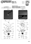
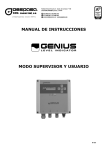
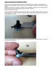
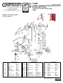
T-200
Código/code 68650
CARRO TRANSPORTADOR-ELEVADOR
DE BIDONES 300Kg
Tels. ++34(9)73 451072 – 451164 – 451270
Fax ++34(9)73 445000 – 448400
Partida Horta d’Amunt, s/n – Apartado de Correos nº 149
E-25600 BALAGUER (Lleida)
E-mail: [email protected] – Internet: http://www.gespasa.es
Transporter-Elevator drum trolley
300Kg
MANUAL DE INSTRUCCIONES
Instruction Manual
Nº
Number
1
2-6-7-11
3
4
5
8-28-32
9
10-39
12
13
14
15-23-33
16-42
17
18
19
DENOMINACIÓN
Description
BASE
Aro
Depósito
Tapón para aceite
Cilindro
Pasador
Cabezal
Bola de acero
Barra de tornillo
Pasador del muelle
Asa
Arandela
Aro
Carcasa de la bomba
Yx-Aro
Precinto antipolvo
Base
O-Ring
Reservoir
Oil plug
Cylinder
Pin
Head
Steel ball
Screw rod
Spring pin
Grip
Washer
O-Ring
Pump housing
Yx-Ring
Dust seal
Nº
Number
20
21-41
22
24
25-29
26-30-43
27-31-47
34
35-56-57
36
37
38
40
44
45-48-49
46
DENOMINACIÓN
Description
Pistón
Muelle
Protector antipolvo
Bloque
Tornillo de conjunto
Perno
Tuerca
Pasador del resorte
Enlace
Pedal
Montaje de la palanca
Asa del mango
Guía del muelle
Montaje de la ruedecilla
Tornillo
Arandela del muelle
Piston
Spring
Dust protector
Block
Set screw
Bolt
Nut
Snap pin
Link
Pedal
Handle Assembly
Handle grip
Spring guide
Caster assembly
Bolt
Spring washer
Nº
Number
50
51
52
53-62-65
54
55
58
59
60
61-73
63-71
64-68
66-67
72
74
75
76
DENOMINACIÓN
Description
Casquillo
Rueda
Tapón de goma
Arandela
Tuerca
Montaje de la barra
Gancho
Soporte
Goma
Pasador
Pasador del resorte
Perno
Tuerca
Cojinete
Muelle largo
Brazo guía
Estructura
Bushing
Wheel
Rubber plug
Washer
Nut
Rod assembly
Hook
Stand
Rubber
Pin
Snap pin
Bolt
Nut
Bearing
Returning
Guiding arm
Frame
M-159
MANUAL DE INSTRUCCIONES T-200
Instruction Manual
1. AVISOS DE SEGURIDAD Y PRECAUCIONES
1. SAFETY WARNINGS AND PRECAUTIONS
1. Asegúrese de entender y seguir todas las instrucciones
antes de usar este aparato.
2. Cuando trabaje con el carro transportador-elevador lleve
siempre el equipo de seguridad apropiado (zapatos, gafas,
guantes, etc.)
3. Asegúrese que el peso del bidón a levantar es adecuado a
las especificaciones del equipo. No sobrecargue el equipo.
4. Use el equipo únicamente para levantar o transportar los
bidones. No use este equipo como un soporte o para
cualquier otro propósito.
5. Para utilizar el transportador-elevador de bidones con
seguridad colóquelo en una superficie que sea estable, sin
excesivas pendientes, limpia y capaz de sostener la carga.
6. Estabilizar la carga. Asegúrense que la carga permanece
estable en todo momento. No mover la carga a menos que el
bidón esté seguro.
7. Centrar la carga. Centrar la carga antes de asegurarla y
alzarla. Las cargas descentradas pueden dañar los cierres,
causando un fallo del soporte.
NOTA: Cuando se mueva el transportador de bidones,
aseguraros de mantener una distancia de seguridad para
evitar heridas, atropamientos, enganches o pellizcos.
8. Evitar mover el transportador de bidones alrededor de
espectadores. Si el soporte falla, puede ocasionar daños a las
personas que estén alrededor.
9. No realizar ninguna alteración en el soporte. Se deben usar
todos los acoplamientos suministrados por el fabricante.
10. Si no se tienen en cuenta estas anotaciones puede ocurrir
un daño personal o un perjuicio a la propiedad.
AVISO: Los avisos, advertencias e instrucciones comentadas
en este manual de instrucciones no pueden cubrir todas las
posibles condiciones y situaciones que puedan ocurrir. Se
debe entender por el operador que el sentido común y la
prudencia son factores que no pueden ser incluidos en este
producto, pero deben ser suministrados por el operador.
1. Ensure that you understand and follow all instructions
before operating this kit.
2. Always wear suitable security kits (shoes, glasses, gloves,
etc.) when you use the transporter-elevator trolley.
3. Do not overload this kit. Know the weight of the drum being
lifted.
4. Use the kit for lifting only. Do not use this kit for any other
purpose. Do not use it as a stand.
5. Place the transporter-elevator trolley correctly. Only use this
kit on a surface that is stable, level, clean and dry and capable
of sustaining the load.
6. Stabilize load. Ensure that the load remains stable at all
times. Do not move load unless the drum is secured. Lift dead
loads only.
7. Center Load. Center the load before securing and lifting. Off
center loads can damage the seals, causing support failure.
NOTE: When moving the transporter-elevator trolley, be sure
to maintain a safe distance to avoid injury, be careful not to
pinch fingers.
8. Avoid moving the transporter-elevator trolley around
spectators. If the support fails, the load of the drum could
injury a person's feet.
9. No alterations shall be made to the support. Only
attachments supplied by the manufacturer shall be used.
10. Failure to heed these markings may result in personal
injury and/or property damage.
WARNING: The warnings, cautions and instructions discussed
in this instruction manual cannot cover all possible conditions
and situations that may occur. It must be understood by the
operator that common sense and caution are factors which
cannot be built into this product, but must be supplied by the
operator.
2. USO Y CARACTERÍSTICAS
2. INTENDED USE AND FEATURE
Diseñado para levantar y transportar bidones de hasta 300 kg.
- El diseño de la esclusa elevadora sostiene el bidón en una posición
elevada para un fácil transporte.
- El ariete hidráulico resistente con pedal de pie asegura un funcionamiento
rápido.
- Rueda orientable trasera giratoria y ruedas frontales grandes para ayudar
a una fácil maniobra.
Designed to lift and transport drums of up to 300 kg.
- Lift lock design holds drum in raised position for easy transport.
3. ESPECIFICACIONES
3. SPECIFICATIONS
Peso máximo del bidón:
Altura del bidón:
Tara del equipo:
Capacity:
Drum height:
Kit tare:
300 kg
863 mm (mínimo) – 920 mm (máximo)
36,5 kg
- Heavy-duty hydraulic ram with foot pedal for quick operation.
- Rear swivel caster wheel and big front wheels for easy maneuvering.
300 kg
863 mm (min.) – 920 mm (max.)
36.5 kg
4. DESEMBALAJE
4. UNPACKING
Cuando se desembale, asegúrense que todas las piezas están incluidas.
Refiéranse al despiece y a su lista al principio de este manual. Si alguna de
las piezas falta o está rota, por favor póngase en contacto con su
distribuidor tan pronto como sea posible
When unpacking, check to make sure that all the parts are included. Refer
to the Parts Diagram and Parts listing at the beginning of this manual. If any
parts are missing or broken, please connect the distributor as soon as
possible.
5. MONTAJE
5. ASSEMBLY
Durante el montaje, consulten el Despiece y la lista situado al principio de
este manual. Apretar bien las tuercas y los tornillos.
5.1. Acoplar el montaje de la ruedecilla (44) a la estructura (76) usando los
tornillos (45).
5.2. Acoplar la rueda frontal (51) a cada abrazadera de la rueda de la
estructura (76) usando el tornillo (49), el casquillo (50), la arandela (53) y la
tuerca (54).
5.3. Montar el montaje de la palanca (37) al brazo guía (75) usando los
tornillos (68).
5.4. Insertar la parte superior del soporte (59) en el brazo guía (75).
5.5. Montar el soporte (59) a la base (1) usando los tornillos (48).
5.6. Poner la tuerca (67) en la parte superior del soporte (59) y apretar por
encima de las roscas del soporte.
5.7. Acoplar la Base hidráulica de montaje (1) a la estructura trasera de la
sección (76) usando los tornillos (48).
During assembly, refer to the Assembly Drawing and Parts List located at
the beginning of this manual. Securely tighten all nuts and bolts.
5.1. Attach the Caster Assembly (44) to the Frame (76) using Bolts (45).
5.2. Attach the front Wheel (51) to each wheel bracket of the Frame (76)
using Bolt (49), Bushing (50), Washer (53) and Nut (54).
5.3. Mount the Handle Assembly (37) to the Guide Arm (75) using Bolts
(68).
5.4. Insert the top of Stand (59) into the Guide Arm (75).
5.5. Mount the Stand (59) to the Base (1) using Bolts (48).
5.6. Place Nut (67) on top of Stand (59) and tighten over Stand threads.
5.7. Attach the hydraulic assembly Base (1) to rear section Frame (76)
using Bolts (48).
MANUAL DE INSTRUCCIONES T-200
Instruction Manual
5.8. Insertar el montaje de la barra (55) en el soporte (59), mientras
simultáneamente poner el tapón (28) encima de la parte superior del eje
hidráulico (27).
5.9. Acoplar el muelle de retorno (74) desde la parte superior del montaje
de la barra (55) al soporte (59).
5.8. Insert the Rod Assembly (55) into the Stand (59), while simultaneously
placing the Cap (28) over the top of the hydraulic Shaft (27).
6. FUNCIONAMIENTO
6. OPERATION
5.9. Attach the Return Spring (74) from the top of the Rod Assembly (55) to
the Stand (59).
NO PONGAN LAS MANOS EN O ENCIMA DEL GANCHO
MIENTRAS BOMBEEN EL PEDAL PARA ENGANCHAR EL
BIDÓN.
DO NOT PLACE HANDS ON OR NEAR THE HOOK WHILE
PUMPING THE PEDAL IN ORDER TO ENGAGE THE DRUM.
NUNCA DEJEN EL BIDÓN DEMASIADO TIEMPO EN EL
TRANSPORTADOR DE BIDONES.
NEVER LEAVE THE DRUM ON THE TRANSPORTERELEVATOR TROLLEY FOR AN EXTENDED PERIOD OF
TIME.
6.1. Poner el transportador de bidones alrededor del bidón para moverlo
hasta que el lado del bidón toque la estructura del transportador.
6.2. Girar la maneta hidráulica de palanca en el sentido de las agujas del
reloj para preparar el elevador.
6.3. Con el pie, bombear el pedal de bomba inferior (36) hasta que el
gancho (58) enganche el bidón firmemente. Bloquear las ruedas durante
esta operación para reducir el riesgo de dañarse. Asegúrese que el gancho
del elevador agarre la tapa del bidón firmemente. Continúen bombeando la
maneta hasta que el bidón esté fuera del suelo.
6.4. Empujar el bidón en el lugar deseado.
6.5. Girar despacio la maneta hidráulica de palanca en el sentido contrario
de las agujas del reloj para soltar la presión de la bomba y bajar el bidón.
6.6. Sacar el transportador de bidones del bidón.
6.1. Push the transporter-elevator trolley around the drum to be moved until
the side of the drum touches the frame of the truck.
6.2. Turn the hydraulic lift Handle clockwise to prepare the lift.
6.3. With your feet, pump the lower pump Pedal (36) until the Hook (58)
engages the drum firmly. Block the wheels during this operation to reduce
risk of injury. Ensure the lift hook grabs the lid of the drum securely.
Continue pumping the handle unit the drum is just off the ground.
6.4. Push the drum to the desired location.
6.5. Slowly turn the hydraulic lift Handle counter clockwise to release the
pump pressure and lower the drum.
6.6. Pull the transporter-elevator trolley away from the drum.
7. MANTENIMIENTO
7. MAINTENANCE
7.1. General
7.1. General
7.1.1. Periódicamente lubricar las juntas y el ariete hidráulico con un aceite
light como se necesite.
7.1.2. Engrasar todos los enlaces del brazo elevador, ruedas y ruedecillas.
7.1.3. Limpiar el exterior del transportador de bidones con un trapo seco y
limpio.
7.1.4. Si el transportador de bidones se expone a vaho, limpiar en seco con
un trapo limpio y engrasar.
7.1.5. Almacenar el transportador de bidones con el ariete hidráulico
quitado, en un lugar limpio y seco.
7.1.1. Periodically lubricate the joints and Ram with light oil as needed.
7.1.2. Oil all lift arm linkages, wheels and casters.
7.1.3. Clean the outside of the transporter-elevator trolley with a dry, clean
cloth.
7.1.4. If the transporter-elevator trolley is exposed to moisture, wipe dry with
a clean cloth and lubricate.
7.1.5. Store transporter-elevator trolley with piston Ram withdrawn, and in a
clean and dry location.
7.2. Purga de aire del sistema hidráulico
7.2. Purging Air from the Hydraulic System
Las burbujas de aire pueden quedarse atrapadas dentro del sistema
hidráulico, reduciendo así la eficacia del soporte. Purgar el aire del sistema
si baja la eficacia del elevador.
7.2.1. Girar la Maneta de la bomba que libera la válvula del soporte (14) en
el sentido contrario de las agujas del reloj hasta que el ariete hidráulico del
soporte esté completamente bajado. Apretar de nuevo la maneta de la
bomba.
7.2.2. Quitar el tapón de relleno de aceite (4) en el lado del soporte
estirándolo con cuidado y girándolo. Si lo desean, añadir fluido hidráulico a
rellenar por completo. Ver fotos.
7.2.3. Bombear el pedal de pie (36) para elevar el ariete hidráulico del
soporte a su máxima altura.
7.2.4. Girar la maneta de la bomba en el sentido contrario de las agujas del
reloj en 2 vueltas y media. Hacer bajar completamente el ariete hidráulico
del soporte.
7.2.5. Añadir fluido hidráulico al agujero de llenado de aceite a rellenar por
completo.
7.2.6. Sustituir el tapón de aceite.
7.2.7. Limpiar con un trapo cualquier rebose de aceite hidráulico.
Air bubbles can become trapped inside the hydraulic system thereby
reducing the efficiency of the Jack. Purge the air from the system if lift
efficiency drops.
7.2.1. Turn the jack valve release Pump Handle (14) counter clockwise until
the Jack ram is completely lowered. Re-tighten Pump Handle.
7.3. Sustitución del fluido hidráulico
7.3. Hydraulic Fluid Replacing
SUSTITUIR EL FLUIDO HIDRÁULICO UNA VEZ AL AÑO, O
MÁS A MENUDO SI EL USO ES INTENSO. NO PERMITIR
QUE ENTRE EN EL SISTEMA HIDRÁULICO SUCIEDAD O
CUALQUIER OTRA SUSTANCIA QUE NO SEA ACEITE
HIDRÁULICO DE ALTA CALIDAD PARA EL SOPORTE. NO
MEZCLAR DIFERENTES TIPOS DE ACEITE.
7.3.1. Girar la maneta de la bomba (14) en el sentido contrario de las
agujas del reloj hasta que el ariete hidráulico del soporte esté
completamente bajado.
7.3.2. Destornillar completamente la maneta de la bomba (14).
7.3.3. Quitar el tapón de relleno de aceite (4).
REPLACE THE HYDRAULIC FLUID ONCE PER YEAR, OR
MORE OFTEN WITH HEAVY USE. DO NOT PERMIT DIRT OR
ANY SUBSTANCE OTHER THAN HIGH QUALITY
HYDRAULIC JACK OIL TO ENTER THE HYDRAULIC
SYSTEM. DO NOT MIX DIFFERENT KINDS OF OIL
TOGETHER.
7.3.1. Turn the Pump Handle (14) counter clockwise until the Jack ram is
completely lowered.
7.2.2. Remove the filler Oil Plug (4) on the side of the Jack by pulling and
turning it. If desired, add hydraulic fluid to top off. See photos.
7.2.3. Pump the foot Pedal (36) to raise the Jack ram to its maximum height.
7.2.4. Turn the Pump Handle counter clockwise 2-1/2 turns. Push the jack
ram completely down.
7.2.5. Add hydraulic fluid to the oil fill hole to top off.
7.2.6. Replace the Oil Plug.
7.2.7. Wipe up any hydraulic oil overflow with a cloth.
7.3.2. Unscrew the Pump Handle (14) completely.
7.3.3. Remove the filler Oil Plug (4).
MANUAL DE INSTRUCCIONES T-200
Instruction Manual
7.3.4. Quitar el tornillo de drenaje inferior.
7.3.5. Bombear el pedal de pie hasta que vaciar el fluido hidráulico.
Aseguraros de tener un cubo preparado para recoger el fluido vaciado.
7.3.6. Apretar otra vez la maneta de la bomba (14).
7.3.7. Sustituir el tornillo inferior de vaciado.
7.3.8. Rellenar con aceite hidráulico de alta calidad para el soporte al borde
inferior del agujero de relleno de aceite.
7.3.9. Purgar el aire del sistema como se ha descrito anteriormente.
7.3.10. Rellenar con más fluido hidráulico del soporte.
7.3.11. Sustituir el tapón de aceite (4).
NOTA: Deshacerse siempre del aceite usado apropiadamente. Contacte
con su Autoridad local de Materias Usadas Peligrosas para unas directrices
de eliminación del aceite adecuadas.
7.3.4. Remove the lower drain screw.
7.3.5. Pump the Foot Pedal until all the hydraulic fluid drains. Be sure to
have a bucket ready to catch the draining fluid.
7.3.6. Retighten the Pump Handle (14).
7.3.7. Replace the lower drain screw.
7.3.8. Refill with high-quality hydraulic jack oil to the lower rim of the oil filler
hole.
7.3.9. Purge air from the system as previously described.
7.3.10. Top off with more hydraulic jack fluid.
7.3.11. Replace the Oil Plug (4).
NOTE: Always dispose of used oil properly. Contact your local Hazardous
Waste Authority for proper oil disposal guidelines.
8. GARANTÍA
8. WARRANTY
8.1. Todos los productos fabricados por TOT COMERCIAL SA tienen una
GARANTÍA de 12 meses desde su compra, contra cualquier defecto
de fabricación.
8.2. TOT COMERCIAL SA garantiza dentro del período de garantía, el
canje / la reposición de la pieza o del producto defectuoso, siempre
que el material sea enviado a portes pagados a nuestra fábrica, o a
cualquier servicio técnico designado. Después de nuestra inspección
técnica se determinará si la responsabilidad es del fabricante, del
usuario, del instalador o del transporte.
8.3. La garantía no cubre: El uso inadecuado, la negligencia, el abuso, la
corrosión, la manipulación o la incorrecta instalación de los productos,
el uso de repuestos no originales o no correspondientes al modelo
específico. Todos los equipos fabricados y/o comercializados por TOT
COMERCIAL SA deben ser instalados de acuerdo con las normas
facilitadas por el fabricante.
8.4. Los accesorios y productos no fabricados por TOT COMERCIAL SA
están sujetos a la garantía de su fabricante original.
8.5. Por las constantes innovaciones y desarrollo, TOT COMERCIAL SA
se reserva el derecho de modificar las especificaciones de sus
productos y publicidad, sin previa notificación.
8.1. All the products manufactured by TOT COMERCIAL SA have a
WARRANTY of 12 (twelve) months from their purchase, against any
manufacturing defect.
8.2. TOT COMERCIAL SA guarantees in the warranty period, the
change/the devolution of the defective part or product. This material
has to be sent with carriage paid to our factory, or any designed
technical service. After our technical inspection it will be determined
whether the responsibility is from the manufacturer, the user, the
installer, or the delivery.
8.3. The warranty does not cover: Inadequate use, negligence, corrosion,
abuse, manipulation, or the wrong installation of the products, a use of
non-original spare parts, or not concerning to the specific pattern. All
the manufactured and/or commercialized by TOT COMERCIAL SA
equipment must be installed according to the given instructions by the
manufacturer.
8.4. The accessories and the products not manufactured by TOT
COMERCIAL SA are liable for their original manufacturer’s warranty.
8.5. Because of the constant innovations and development, TOT
COMERCIAL SA keeps the right to modify the specifications of its
products and publicity, without prior notice.
Balaguer, julio 2011
Balaguer, July 2011