1
Table of Contents
Spray gun
Safety................................................................................................. 2
Grounding Instructions..................................................................................2
Service............................................................................................... 3
Introduction...................................................................................... 3
Using an HVLP Spray System........................................................... 3
Setup.....................................................................................................................3
Dual Filtration System.....................................................................................3
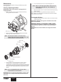
Maintenance..................................................................................... 4
Cleaning/Replacing Filters............................................................................4
Cleaning the Air Hoses....................................................................................4
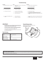
Troubleshooting............................................................................... 5
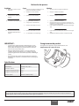
Product Registration........................................................................ 5
Français............................................................................................. 6
Español............................................................................................ 10
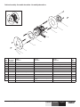
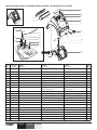
Parts List.....................................................................................14-17
Wiring Diagram.............................................................................. 18
Warranty......................................................................................... 20
Turbine
Air hose
Setup
Use the following procedure to set up your HVLP spray system for
operation.
1. Plug the turbine power cord into a grounded, 3-slot
receptacle.
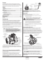
This High Volume/Low Pressure (HVLP) spray system is designed
for applying coatings to surfaces that can be sprayed faster than
brushing or rolling and are too small for traditional airless sprayers.
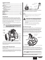
Components of this system include a power switch, a power cord, a
filter warning light, a circuit breaker switch, a dual filtration system, a
cup holder, an air hose, and an air outlet.
The turbine is also equipped with a tool box. It is located on the
reverse side of the turbine and can be used to store projector sets or
any other small spare parts.
Keep the turbine at the maximum possible distance
from the spray area to safeguard against explosion or
fire that may be caused by sparking electrical parts.
NOTE: Some of the graphics in this manual may not exactly
match your turbine and spray gun. All information
and instructions given in this manual applies to all
models except where noted.
2. Prepare your spray gun for operation. Refer to your spray
gun manual for material preparation, setup, and spraying
information.
3. Attach the air hose to the air outlet on the turbine.
4. Attach the air hose to the air inlet on your spray gun.
5. Turn on the turbine and begin spraying.
Dual Filtration System
The turbine has two different air filters— one for atomizing air and
one for cooling air. The atomizing air filter is a two-stage, fine mesh
filter designed to trap particles that may damage your finish. The
atomizing air is discharged through the nozzle of the spray gun
where it atomizes the coating material. The cooling air filter is a
coarse mesh filter designed to allow the proper amount of air flow
through the turbine for cooling purposes. Cooling air is exhausted
through the cooling air discharge on the front of the turbine.
Circuit
breaker
switch
Filter
Whip hose
important: Do not attach the short air whip hose directly to
the turbine, as the hose will become damaged.
Introduction
Filter
warning
light
Coupling
Air inlet
Cup holder
rear of turbine
Filter
(in end of
filter can)
Power
switch
Atomizing air
discharge
Atomizing air
intake
Air outlet
*Air hose not pictured
With this HVLP spray system, you can achieve the highest quality
professional finish possible with little or no preparation or setup time.
Please review all the information contained in this manual before
operating the system.
Cooling air
intake
Cooling air discharge
Filter Warning System
The filter warning system on your turbine consists of a red filter
warning light on the front control panel and an air flow switch inside
the turbine. When the air flow switch does not detect the appropriate
amount of air flowing through the turbine, the filter warning light will
come on to indicate that it is time to clean or change the filters.
Using an HVLP Spray System
Refer to the following information to operate and understand your
HVLP spray system.
Your system may include a short air (“whip”) hose. The short hose
should be connected to the longer hose or a remote spraying system
(sold separately) and NOT directly to the turbine. See your spray gun
instruction manual for complete instructions.
NOTE: The filter warning system does not shut down the
turbine.
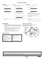
IMPORTANT: Clean filters regularly. Clogged filters can cause
excessive heat and possibly damage the turbine.
© Titan Tool Inc. All rights reserved.
3
English